
EE220 / EE223 Assignment 1 : Characterization of NMOS
EE220 / EE223 Assignment 1 : Characterization of NMOS / PMOS Transistor
Using cadence for first time ? Well, this document is a right place to start with.This document is
intended for SJSU students only.As of 2014, a student can use one of the following versions of Cadence
Virtuoso :
Cadence Virtuoso 6.1.3 Cadence Virtuoso 6.1.5.500 Cadence Virtuoso 6.1.6 (For most classes – EE166, EE224 or any other VLSI classes)
(Newer version , for EE223 but highly required for EE220)
(For EE220 / EE230)
Although you can use any version of Virtuoso on your Unix machine , it’s important that you stick to
same version of Cadence Virtuoso throughout your semester.
1.
Go to your Home Directory using your Konsole (name for Terminal in KDE desktop environment), type cd 45 and then type ./virtuoso into your Konsole window.
OR
Simply go to your cadence folder and double click on “virtuoso” file This tutorial is created by ISAs for EE220 and EE223 only. The tutorial follows Assignment 1/Lab 1 common for these courses.Created for SJSU students.
2.
This is your main window.Remember, if you ever close this window, it means your are quitting Cadence.
This tutorial is created by ISAs for EE220 and EE223 only. The tutorial follows Assignment 1/Lab 1 common for these courses.Created for SJSU students.
3.
Next, click on Tools > Library Manager
This tutorial is created by ISAs for EE220 and EE223 only. The tutorial follows Assignment 1/Lab 1 common for these courses.Created for SJSU students.
4.
Next, go to File > New > Library
This window will help you create a new Library.A library is a collection of smaller circuits (called cells) and together can be used in a schematic (for example a schematic if inverter which comprises of cells like nmos, pmos, vdc, gnd etc)
Here, we are creating an empty library
called EE220x , which you will be usuing
throughout your semseter to store all your
cells / schematics.
6.
This tutorial is created by ISAs for EE220 and EE223 only. The tutorial follows Assignment 1/Lab 1 common for these courses.Created for SJSU students.
Make sure that you select this option.You don’t wanna
miss this one!
7.
When you attach your library to gpdk045, it means
you are assigning use of technology from 45nm
models.
8.
This tutorial is created by ISAs for EE220 and EE223 only. The tutorial follows Assignment 1/Lab 1 common for these courses.Created for SJSU students.
So, now you have your library (which
is empty at present) and a bunch of
other libraries too.Remember analogLib
can be used to instantiate (fancy word
to insert a component from library,
you will hear this a lot from digital
design students) components like
voltage sources, gnd and other basic
components like resistors, capacitors
etc.Always use gpdk045 to instiantiate
transistor (nmos_1v , pmos_1v) in your
schematic.
9.
This tutorial is created by ISAs for EE220 and EE223 only. The tutorial follows Assignment 1/Lab 1 common for these courses.Created for SJSU students.
In your library manager, goto File>New>Cell View
Now let us create our first Lab1 assignment.Make sure that you select type as schematic and always open application with SchematicsXL (it’s better than SchematicL and in a short while we will tell you why.Make sure that you SchematicXL throughout this tutorial).
10.
Once you click OK, you will come to Schematic view
This tutorial is created by ISAs for EE220 and EE223 only. The tutorial follows Assignment 1/Lab 1 common for these courses.Created for SJSU students.
11.
This tutorial is created by ISAs for EE220 and EE223 only. The tutorial follows Assignment 1/Lab 1 common for these courses.Created for SJSU students.
Press “I” (shortcut got Instance) or go to Create>Instance.Click on symbol and hit Enter.
This tutorial is created by ISAs for EE220 and EE223 only. The tutorial follows Assignment 1/Lab 1 common for these courses.Created for SJSU students.
12. So, now you have got your nmos on your schematic.If you click on it, yowill come across a property
editor on you bottom left corner.
This tutorial is created by ISAs for EE220 and EE223 only. The tutorial follows Assignment 1/Lab 1 common for these courses.Created for SJSU students.
12.
You can even click on your instance and goto property editor by pressing the key “Q”.
Instance name : It’s always a
good practice to rename your
instance
This is where you can change
specs for your nmos.Here the
length of transistor is 45nM
while the min width is 120nM
(you can go all the way upto
10uM).Another useful parameter
is Finger and Finger width.By
increasing the numbers of
fingers, you would thus be
increasing resistance and thus..
(do you homework, guess how it
is gonna affect your design)
This tutorial is created by ISAs for EE220 and EE223 only. The tutorial follows Assignment 1/Lab 1 common for these courses.Created for SJSU students.
13. Now we will add vdc (Vgs, Vdc), gnd connections, draw wires and name them (To draw wires, use
shortcut key “P” and to rename them, click on wire and use shortcut key “L” and then add wire name.You
can find both these options in menu as Create>Wire(narrow) to create wire and Create> WireName to name
it)
This tutorial is created by ISAs for EE220 and EE223 only. The tutorial follows Assignment 1/Lab 1 common for these courses.Created for SJSU students.
14. Now, it’s time to run simulation. Remember we told you to use ADEL ? Well, you can open ADEL by
going to menu Launch>ADEL
This is what it looks like.On you left are you Design Variables, to your right is Analyses window and
lower right bottom is your Outputs.Before we go on to explain what they mean, it’s always important to
check and save your schematics to check for any warnings/error (netlist).
This tutorial is created by ISAs for EE220 and EE223 only. The tutorial follows Assignment 1/Lab 1 common for these courses.Created for SJSU students.
15. Before you run or we explain you how to use ADEL, make sure that you select model library.Let’s
not get into why we have to run TT (typicaltypical, in some old versions this is equivalent to NN which
is normalnormal).For this, on your ADEL window, goto Setup>Model Libraries and you will come across
this window :
WAIT – Unless you wanna get your unix account frozen , don’t select this option.Most students fail to
realize that in Cadence 6.1.3, you gotta get the .scs file from Prof.Jones’ directory.So now type this
on your terminal :
This tutorial is created by ISAs for EE220 and EE223 only. The tutorial follows Assignment 1/Lab 1 common for these courses.Created for SJSU students.
When you run this command, these files will
be copied to your /Home/ directory.The one
under interest (godfather of all files) is
gpdk045.scs
Now when you goto your ModelLibrarySetup window, you will have gpdk045.scs visible under your Global
Model Files.By default the section is mc and so it’s your job to go to this menu and select tt everytime
you run ADEL (Note: you don’t have to copy gpdk045.scs files from Prof.Jones’ folder everytime you run
ADEL, it’s just a one time step)
This tutorial is created by ISAs for EE220 and EE223 only. The tutorial follows Assignment 1/Lab 1 common for these courses.Created for SJSU students.
16.
Now go back to SchematicsXL and then Select your Vds source to assign a D.C voltage to your Vds source.Now, there are two ways – either you can assign a fixed voltage in your DC Voltage field or you can assign a variable like we have assigned here called ds (acronym for drainsource).This is called a Design Variable.We even assigned design variable gs to Vgs voltage source.
This tutorial is created by ISAs for EE220 and EE223 only. The tutorial follows Assignment 1/Lab 1 common for these courses.Created for SJSU students.
17.
Now go back to your ADEL window and right click on Design Variables field and click on Copy from Cell View. Once you click on it, notice that ds and gs from schematic is copied to your ADEL test environment. What does this mean ? It means that now you can control your Vgs and Vds voltages from
ADEL much like your Function Generator in Lab.
This tutorial is created by ISAs for EE220 and EE223 only. The tutorial follows Assignment 1/Lab 1 common for these courses.Created for SJSU students.
18. Also make sure that you assign some voltage (no matter anything for sake of cadence) to your design
variable. Your simluation will encounter an erro if you leave this field blank.
19.
When you click on Analyses>Choose in ADEL you will get this windows. This allows you to select the
type of simulation you wanna run on your circuit in schematics.You use transient if you want to plot let’s say voltage vs time or current vs time or any quantity vs time
This tutorial is created by ISAs for EE220 and EE223 only. The tutorial follows Assignment 1/Lab 1 common for these courses.Created for SJSU students.
For this tutorial we are gonna use d.c. analyses which is first by sweeping Vgs and keeping Vds at a
constant voltage and then by sweeping Vgs and then keeping Vds at a fixed voltage. For this tutorial we
will just show you how to do the former , the latter simulation is just a repetition of what we will be
covering in coming few pages.Thus we will be plotting Ids vs Vgs for a fixed Vds and then using
Calculator in ADEL we will show you how to plot rds vs This tutorial is created by ISAs for EE220 and EE223 only. The tutorial follows Assignment 1/Lab 1 common for these courses.Created for SJSU students.
Notice that we have ticked Design Variable and selected gs as we wanted to sweep Vgs for fixed value of
Vds.
You need to define the nature of sweep range , here we are sweeping from 0v to 1v with 10mV increment
steps. Feel free to explore other sweep types (we have used Linear sweep type for this example).
20. Now you gotta select the outputs across that you wanna observe. Since we are already sweeping Vgs,
that becomes our Xaxis, while if we wanna see the effect on drain current Ids for changing gatesource
voltage Vgs, we will select Ids as observable output to represent it on Yaxis.For this, goto
Outputs>Setup.
This tutorial is created by ISAs for EE220 and EE223 only. The tutorial follows Assignment 1/Lab 1 common for these courses.Created for SJSU students.
Now click on From Schematic and then goto your Schematics window and then select the Drain node and then
press the Esc key.You will notice that drain node is selected on your Settings Output windows in ADEL.
Rule of thumb :
To select voltage as output – always click on wire whose voltage is to be determined in Schematics
To select current as output – always click on node of transistor/voltage source or any other component
on your schematic. Note that cadence will always measure current entering the node.
Make sure that you save state by going to
Sessions>Save State and selecting Cellview.By
doing this , you can directly open your ADEL
session from Library Manager saved as
spectre_state1 in our example.This saves a lot of time when you have to leave your design halfway.
Now click on OK.
This tutorial is created by ISAs for EE220 and EE223 only. The tutorial follows Assignment 1/Lab 1 common for these courses.Created for SJSU students.
21.
The fruit of going through 23 pages worth of instructions : your first plot!
This is called a graph plot. Now in Cadence 6.1.3 you can save this file as image (png,bmp etc) but
the quality is gonna be really bad.One way to get good pictures is by going to File>Print and make sure that you select the option Print to File.
This tutorial is created by ISAs for EE220 and EE223 only. The tutorial follows Assignment 1/Lab 1 common for these courses.Created for SJSU students.
Then click on Print and save the file in your documents.This is a postscript file, you can use any image
editor or PDF viewer to open and rotate this file (it’s high quality graphics compared to Save as image
option).
So far we have seen the effect of Vgs on Ids for a fixed value of Vds.What is we want to see this Vgs
effect on Ids for various values of Vds ? The answer to this is parametric analysis.Parametric analysis
lets you see Ids vs Vgs plots for various values of Vds.Thus, to perform paramtric analyses, goto
Tools>ParametricAnalyses and then since you have to parametrize Vds , enter Variable name as ds.
This tutorial is created by ISAs for EE220 and EE223 only. The tutorial follows Assignment 1/Lab 1 common for these courses.Created for SJSU students.
Again, the type of Step control is linear (linear increments of Vds).Note that if your step size goes to
10m, you will have to wait for minutes instead of seconds to finish your simulation.
This tutorial is created by ISAs for EE220 and EE223 only. The tutorial follows Assignment 1/Lab 1 common for these courses.Created for SJSU students.
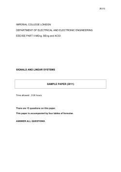
Voila – this is the output. Looks beautiful, isn’t it ? Well this is your Ids plot for various values of
Vgs.What does this plot say ? Well first of all, Ids for any Vds value rises only after roughly 0.4
volts.This tells us that the threshold voltage of this nmos is roughly 400mV.Next, the current curve
slope becomes high as we increase the value of Vds – a crucial observation helpful for matching
transistor biasing (which you might encounter in later assignments/Lab while you will be designing
amplifiers or
LNA)
This tutorial is created by ISAs for EE220 and EE223 only. The tutorial follows Assignment 1/Lab 1 common for these courses.Created for SJSU students.
22. You might have studied about transconductance gm in your theory class (if not, ask your Professor
about it).So lets plot the transconductance of this nmos1v.To do that , goto Tools>Calculator in your
ADEL window.
This tutorial is created by ISAs for EE220 and EE223 only. The tutorial follows Assignment 1/Lab 1 common for these courses.Created for SJSU students.
Now click on idc (2nd row 3rd Columnn on top of calculator window) and after clicking on idc, goto your
Schematics windows and select the drain node of transistor.
Now, locate the function deriv in special functions section on bottom of calculator window.Once you
click on it, you will get something like this
What did we do so far ? Well, we wanted to find transconductance, so we found it using this equation and thus we used deriv function to find derivative of Ids vs Vgs.
Now, make sure that you select New Subwindow (if you select, append, your gm
plot will be overwritten on your existing plot of Ids vs Vgs with parametrized
Vds).Then click on button with a calculator and sine wave ========>>
This tutorial is created by ISAs for EE220 and EE223 only. The tutorial follows Assignment 1/Lab 1 common for these courses.Created for SJSU students.
The result :
Notice how transconductance changes with increasing Vgs.The plot on left is Ids vs Vgs for various Vds
while plot on right is gm vs Vgs for various Vds values.If you look, you have to answer two questions –
What values of Vgs yields maximum gm ? And why gm reaches maximum and then decreases ? These are the
questions that you gotta answer yourself ! This ends just one part of 4 parts in Lab 1.
This tutorial is created by ISAs for EE220 and EE223 only. The tutorial follows Assignment 1/Lab 1 common for these courses.Created for SJSU students.
So far,
We have found Ids vs Vgs for various values of Vds and plotted gm (transconductance) vs Vgs for various
Vds values using calculator function.
Now you gotta perform similar set of steps to find,
Ids vs Vds for various values of Vgs and plot rds (dynamic resistance) for various Vgs values , again,
using calculator function (rds is {deriv[Ids]/deriv[Vds]}^1 ; hint – use deriv on Ids and then use
inverse function in calculator).
Once you have performed these two parts, you gotta perform them on pmos1v device !
This brings an end to Lab 1 for EE223 students (and first half of Lab 1 for EE220 students, the second
half will be emailed by your Professor soon).
Some thoughts:
1.
Try to explore as many functions as you can in calculator.They are really helpful and you can even use calculator to sometimes automate your task to find any specific value in your simluation plot graphs.
2.
We haven’t discussed about model parameters – when running d.c analyses make sure that you select save d.c operating points and after running simulation, go to Result>Print>Model Parameters on your
ADEL window and then select your nmos/pmos on Schematic windows.What do you see ?
3.
Sometimes your Unix session might disconnect or you might abruptly logout of your system while cadence is still running.In this case , cadence creates a .cdslck lock files and when your rerun your cadence virtuoso again, you might come across this error :
*WARNING* file /home/ugrad/(yourusernamehere)/CDS.log Connection refused
or you won’t be able to edit your schematic file. In that case you can simply delete all lock files
in your cadence directory. However we prefer to clear these lock files using this command that we use in our everyday simulation sessions :
find . name "*.cdslck" exec rm f {} \;
4.
Can you create such a graph ? Make sure that you spend some time experimenting with various options
in your graph editor
This tutorial is created by ISAs for EE220 and EE223 only. The tutorial follows Assignment 1/Lab 1 common for these courses.Created for SJSU students.
Hope you find this tutorial helpful.Feel free if you come across any mistakes in this
tutorial. SParameters tutorial might be uploaded soon.
This tutorial is created by ISAs for EE220 and EE223 only. The tutorial follows Assignment 1/Lab 1 common for these courses.Created for SJSU students.


© Copyright 2026