
D E S I G N G U... & P A T T E R N ...
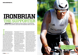
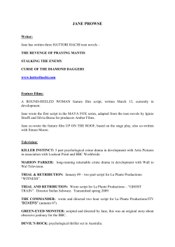
DESIGN GUIDELINES & PATTERN BOOKS Design Guidelines and Pattern Books are essential tools for ensuring a successful transition from project vision to built reality. These regulatory documents vary with the needs of the client, but the common goal is to educate, inspire and guide the efforts of architects, builders and buyers during the process of design and construction. As planners and architects, Historical Concepts addresses community patterns and public spaces, as well as the intricacies of massing and building details. We have a wide breadth of experience in creating Design Guidelines and Pattern Books for projects ranging from Traditional Neighborhood Developments to Resort Communities to Historic Infill to Conservation Developments. HISTORICAL CONCEPTS architects, planners & place-makers Excerpts from Design Guidelines B AY SID E V ILLAG E at BAY CRE E K "AYSIDE6ILLAGE "AY#REEK 1 ()34/29#(!2!#4%2 2 6 Identifying Features of the Queen Anne Victorian Style 4 3TEEPLYPITCHEDROOFSOFIRREGULARSHAPEUSU ALLYWITHADOMINANTFRONTFACINGGABLE !SSYMETRICALMASSINGANDCONlGURATIONSOF ELEMENTS 5SEOFDECORATIVEDETAILINGTYPICALLYOFCUT WOOD 7 6ARIED USE OF EXTERIOR lNISHES OFTEN CLAP BOARDSIDINGORBOARDANDBATTEN 3 !PERIODOFRAPIDINDUSTRIALIZATIONANDTHEPROLIFERATIONOFRAILROADSBETWEEN ANDLEDTODRAMATICCHANGESIN!MERICANHOUSEDESIGNANDCONSTRUCTIONTECH NIQUES4HENEWLYDEVELOPEDBALLOONFRAMEMADEUPOFLIGHTWOODFRAMINGFREED HOUSESFROMTHEIRTRADITIONALBOXLIKESHAPE)NADDITIONPRODUCTSRESULTINGFROMIN DUSTRIALIZATIONPERMITTEDMANYCOMPLEXHOUSECOMPONENTSTOBEMASSPRODUCEDAND SHIPPEDTHROUGHOUTTHECOUNTRYATRELATIVELYLOWCOST 4HE6ICTORIAN3TYLEWHICHINCLUDES1UEEN!NNEAND3TICKBUILDSONTHETRADITIONS EMBODIEDINASERIESOF0ATTERN"OOKSUSEDBYBUILDERSINTHESECONDHALFOFTHENINE TEENTHCENTURY4HESEGREWOUTOFESSAYSOFANUMBEROFARCHITECTSFAVORINGNATURALISM INARCHITECTUREANDLANDSCAPEDESIGN!STHESE0ATTERN"OOKSWEREMOREWIDELYUSED THESTYLEWITHITSORNAMENTEDPORCHESANDROOmINESBECAMESOWIDELYADOPTEDASTO SEEMTOBEATRUE!MERICANVERNACULARSTYLE 7INDOWS AND DOORS WITH VERTICAL PROPOR TIONSANDORNATETRIM 5 4ALLCHIMNEYSUSUALLYOFBRICKWITHDECORA TIVEFEATURESORCAPS 0ARTIAL OR FULLWIDTH ASYMMETRICAL PORCH USUALLY ONE STORY HIGH AND EXTENDED ALONG ONEORBOTHSIDEWALLS THE QUEEN ANNE VICTORIAN STYLE ARCHITECTURAL PATTERN BOOK "AYSIDE6ILLAGE "AY#REEK .BTTJOH%JBHSBNT Narrow Front -ASSING#OMPOSITION L-Shaped L-Shaped Hipped Roof (IPPED2OOFWITH,OWER#ROSS'ABLES 4WO3TORY-INIMUM 4HISFORMACCOUNTSFORMORETHANHALFOFALL1UEEN !NNE HOMES 4HE MAIN HIPPED MASS HAS A STEEP PITCHOFAMINIMUMOFIN4HEREAREOFTENTWO CROSSGABLESONEINFRONTANDONEONTHESIDETHAT COMEOFFOFTHISMAINBODY7HENTHEYAREPRESENT THEY ARE PLACED TO ONE SIDE OF THE RESPECTIVE FA½ADE ANDNOTINTHEMIDDLE4HEHIPPEDROOFMAYHAVEA RIDGEMAYBEPYRAMIDALANDMAYEVENHAVEASIMPLE mATROOFDECKATTHEPEAK!TOWERISATYPICALACCENT MASSTHATISOFTENPLACEDATONECORNEROFTHEFRONT FA½ADE/NESTORYPORCHESTHATEMPHASIZETHEFRONT ENTRYAREAMINIMUMREQUIREMENT .ARROW&RONT'ABLE4WO3TORY-INIMUM ! NARROW FRONT HOME IS A FRONT GABLED RECTANGULAR VOLUMEWITHAROOFPITCHRANGINGFROMINTO IN FOR THE MAIN BODY 4HREE BAY COMPOSITIONS ASYMMETRICALLY ARRANGED WITH FULLFRONT ONESTORY PORCHES ARE MOST COMMON 7RAPAROUND PORCHES WITHEMPHASISOVERTHEENTRYBAYAREENCOURAGED ,n3HAPED4WO3TORY-INIMUM #ROSS GABLED VOLUME WITH A IN TO IN PITCHED ROOF FACING THE STREET 4HE WIDTH OF THE GABLE FACING THE STREET IS TYPICALLY TWOlFTHS OF THAT MAINBODY4HISMASSINGTYPICALLYACCOMMODATESA ONE OR TWOSTORY CONTINUOUS PORCH WITH A SHED OR HIPPEDROOFTHATDIESINTOTHESIDEOFTHEPROJECTING WING!TOWERIFPRESENTWILLMOSTOFTENBELOCATED AT THE INTERSECTION OF THE @, AND BE SQUARE ROUND POLYGONAL #OMBINATIONS -ORE COMPLEX FORMS AND LARGER LIVING SPACES ARE TO BE CREATED BY COMBINING SIDE WINGS ANDOR REAR WINGSWITHTHEMAINBODY0RIMARYPORCHESAREAN ADDITIONTOTHEMASSANDAREEITHERONEORTWOSTORIES TALL 3ECONDARY PORCHES MAY BE SUBTRACTIVE FROM THEMAJORORMINORMASSESANDUSUALLYOCCURONTHE SECONDORTHIRDmOORS'ABLEDORARCHEDDORMERSMAY BEADDEDTOINTRODUCELIGHTINTOHALFSTORYANDATTIC SPACES 4HE ARCHITECTURAL CHARACTER OF THE ATTACHED PARTSSHOULDMATCHTHATOFTHEMAINBODY"ECAUSE OFTHEADVENTOFLIGHTWOODFRAMINGPROJECTIONSAND RECESSESWEREUSEDWITHABANDONTOBREAKUPTHEmAT SURFACES OF PAST ARCHITECTURAL STYLES 4OWERS FULL HEIGHTBAYSCUTAWAYBAYSANDELABORATEOVERHANGS EXPRESSEDTHISNEWFOUNDFREEDOM &A½ADE#OMPOSITION 1UEEN !NNE FA½ADE COMPOSITION IS LIKE GOOD JAZZ 4HE NOTES MUST BE PLAYED RIGHT BUT THEY CAN BE PLACEDINANYORDERTHATPRODUCESAmOW)TWASBASED UPON THE LOCALIZED SYMMETRY OF INDIVIDUAL PARTS COMINGTOGETHERINTOANASYMMETRICALWHOLE!LLOF THEPARTSRELATEBUTARESTILLSUBORDINATETOTHEMAIN BODY)NDIVIDUALDOUBLEHUNGWINDOWSARETHEMOST COMMON TYPE &RONT DOORS ARE GENERALLY LOCATED IN THECORNEROFNARROWHOUSESANDATTHEJUNCTUREOF MAJORANDMINORMASSESOFTHEWIDEHOUSES0AIRED ORBAYWINDOWSAREOFTENUSEDINTHEFORWARDGABLE OFTHE,SHAPEDMASSINGTYPES"AYWINDOWSMAYBE ONEORTWOSTORIESTALL!TMOSTGABLEENDSTHEWALL SURFACEWASACCENTEDBYADIFFERENTPATTERNOFSIDING OR SHINGLES 4HE GABLE APEX WAS ALSO lLLED IN WITH DECORATIVE BRACKETRY THAT RELATED TO THE ORNAMENT USEDONTHERESTOFTHEHOME THE QUEEN ANNE VICTORIAN STYLE ARCHITECTURAL PATTERN BOOK HISTORICAL CONCEPTS design guidelines / 2 Excerpts from Design Guidelines B AY SID E V ILLAG E at BAY CRE E K "AYSIDE6ILLAGE "AY#REEK 7INDOWS$OORS 3TANDARD7INDOWS 3TANDARD 7INDOWS ARE DOUBLE HUNG WITH SASHES AND PANES OF VERTICAL PROPORTIONS 4HE PROMINENT SASH PATTERNSINCLUDEOVEROVEROVER!VERY COMMONANDENCOURAGEDSASHPATTERNISONELARGEPANE SURROUNDED BY SMALL SQUARE PANES OF VARYING COLORS OVERALARGESINGLEPANE4HECLASSICALBASEDSUBTYPES OF1UEEN!NNEHOMESWILLEITHERHAVETHEOVEROR OVERSASHES!CCENTWINDOWSAREOFTENlXEDAND MAYBEROUNDOVALORPOLYGONALINSHAPEWITHAWIDE VARIETY OF LIGHT PATTERNS ,EADED AND STAINED GLASS IS ENCOURAGEDINACCENTWINDOWS 3TANDARD7INDOWS 3TANDARD$OORS $OORSARECENTEREDINTHEIRBAYSANDAREEITHERPANELED OR GLAZED $OORS CAN BE DOUBLE OR SINGLE AND OFTEN INCLUDE SIDELIGHTS AND TRANSOMS ,EADED AND STAINED GLASSISENCOURAGEDINTRANSOMSANDSIDELIGHTS 3PECIAL7INDOWS !NGLED OR STRAIGHT BAY WINDOWS PAIRED OR TRIPLE WINDOWS AND DORMER WINDOWS WITH A TRIANGULAR OR SEGMENTEDPEDIMENTAREENCOURAGEDTOACCENTOVERALL FORM "AY WINDOWS MUST EXTEND TO THE GROUND OR BE VISUALLY SUPPORTED BY HEAVY SIMPLE OR ELABORATE BRACKETS !T GABLE ENDS OR ABOVE ENTRANCES SMALL SQUARE RECTANGULAR OR ROUNDTOP WINDOWS ARE TO BE USEDASACCENTS 3TANDARD$OORS 4RIM 7INDOWANDDOORCASINGANDTRIMMUSTBEAMINIMUM OFvWIDEvPREFERREDANDMUSTPROTRUDE FROMTHEADJACENTWALLSURFACE7INDOWANDDOORSILLS MUSTBEAMINIMUMOFINCHESTHICK 3PECIAL7INDOWS THE QUEEN ANNE VICTORIAN STYLE ARCHITECTURAL PATTERN BOOK "AYSIDE6ILLAGE "AY#REEK 0ORCHES 4HEPORCHISTHEONEOFTHESTRONGESTARCHITECTURALELEMENTSONA1UEEN!NNEHOME4HEPORCHCANBE PARTIALORFULLWIDTHUSUALLYONESTORYANDHASEMPHASISPLACEDONTHEBAYWHEREACCESSISGAINEDTOTHE PORCH)NADDITION1UEEN!NNEPORCHESOFTENWRAPTHECORNEROFTHEHOMEINANACCENTEDWAY3ECOND mOORPORCHESOFTENACCENTANELEMENTONTHEFA½ADEBELOWANDALSOCANBESEENASARECESSINTOTHEMASS RATHERTHANANADDITIVEELEMENT4HESTYLEISALSODETERMINEDBYTHEPRESENCEOFDECORATIVEDETAILINGON COLUMNSBALUSTERSSPANDRELSANDFRIEZES Brackets Porch Elevations Columns 0ORCH2OOFS%AVES 4HE "AYSIDE 1UEEN !NNE HOME MAY HAVE ONE OR TWOSTORYPORCHESWITHmATSHEDORSHALLOWHIPPED ROOFS4HESHEDORHIPPORCHESRANGEINPITCHFROM INTOINANDTHEEAVEATTHEENDOFAPORCH MUSTDIEINTOAPROJECTINGMASSOFTHEHOUSE)TIS UNACCEPTABLEFORANYPARTOFAPORCHEAVETOPROTRUDE BEYONDTHECORNEROFTHEMAINBODYOFTHEHOUSE 0ORCH,OCATIONS &ULLFRONTONEORTWOSTORYPORCHESAREENCOURAGED ON "AYSIDE 1UEEN !NNE HOMES 4HE PORCHES CAN BEUSEDTOWRAPTHECORNEROFTHEHOUSEORlLLINTHE VOIDCREATEDBYAN,SHAPEDPLAN0ORCHBAYSSHOULD BEVERTICALLYPROPORTIONED #OLUMNS2AILINGS #OLUMNS AT PORCHES INCLUDE APPROPRIATE CLASSICAL COLUMNSOFTHELESSOPULENTORDERSTURNEDSPINDLES WITHAvMINIMUMBASEANDSQUARECOLUMNSEITHER BOXEDORSOLIDWITHTHECORNERSCHAMFERED &RONT DEPTHMINIMUM RECOMMENDED 3IDE2EAR DEPTHMINIMUM RECOMMENDED 4URNEDORSQUAREBALUSTERSMUSTADHERETOTHELOCAL BUILDINGCODEBUTINGENERALMUSTBESPACEDNOMORE THAN v APART X MATERIAL WITH CUTOUTS IS ALLOWED PERDESIGNAPPROVAL 0ORCHDECK vMINIMUMFROMlNISHEDGRADE "RACKETS&RIEZES "RACKETSRANGEFROMSIMPLEDESIGNSCUTFROMBOARDS TO MORE ELABORATE TURNED WOOD OR JIGSAWCUT OPEN WORK AND ARE TO BE A MINIMUM OF v THICK /VER KEY ENTRY AND CORNER LOCATIONS ARCHWAY BRACKETING MAYBEUSED4URNEDBALUSTERSMAYBEUSEDINBOTH THEPORCHRAILINGSANDINFRIEZESSUSPENDEDFROMTHE PORCHROOFSTRUCTURE 3ECOND&LOOR mOORTOCEILINGHEIGHTTOBEA MINIMUMOF 4HE0RIMARYPORCHDIMENSIONSAREASFOLLOWS &IRST&LOOR mOORTOCEILINGHEIGHTTOBE MINIMUMOF 3ECONDARY ACCENT PORCH DIMENSIONS WILL BE DETERMINEDPERDESIGNBUTMUSTALLOWTHEUSAGEBY ATLEASTONEHUMANSITTINGCOMFORTABLYINACHAIR Porch Section THE QUEEN ANNE VICTORIAN STYLE ARCHITECTURAL PATTERN BOOK HISTORICAL CONCEPTS design guidelines / 3 Excerpts from Design Guidelines B AY SID E V ILLAG E at BAY CRE E K "AYSIDE6ILLAGE "AY#REEK #OLORS -ATERIALS 4HISSTYLEEMBODIESARICHNESSOFDETAILANDCOMPLEXITYOFMASSINGNOTSEENBEFOREITBECAMETHEDOMINANTHOUSEFORMDURING THEINDUSTRIALREVOLUTION4HEEXOTICANDEXPRESSIVENATUREOFTHISSTYLEISBESTCAPTUREDINAPALETTEOFRICHANDBOLDEARTHTONES THATSTAYTRUETOTHEREGIONBUTCOMPLIMENTANDACCENTUATETHEDETAILINGOFTHISCREATIVEANDINVENTIVESTYLE 4HESE MATERIALS AND PATTERNS ARE STRONGLY ENCOURAGED AS THEY REmECT THE TRUE HISTORIC CHARACTER OF THE#APE#HARLESVERNACULARALTHOUGHTHEYDONOTREmECTALLOFTHEPATTERNSANDMATERIALSALLOWED !LTERNATIVEMATERIALSANDPATTERNSSHOULDREmECTASIMILARHISTORICCHARACTER!LLMATERIALSANDPATTERNS WILLBEAPPROVEDONABYBUILDINGBASIS!PPROVALWILLCOMEONLYFROMTHE"AYSIDE6ILLAGE!2" #OLORSHOULDBEUSEDTOEMPHASIZETHEMANYTEXTURESOFTHISHIGHLYORNATESTYLE&OREXAMPLEWOODSHINGLESCANANDSHOULD BEPAINTEDADIFFERENTCOLORFROMTHEWOODSIDING)NADDITIONCOLORSHOULDBEUSEDTOACCENTUATEARCHITECTURALDETAILSSUCH ASBRACKETSANDAPPLIEDORNAMENTATIONSUCHASCARVINGSMEDALLIONSETC(OWEVERNOMORETHANFOURSEPARATECOLORSSHOULD BEUSEDINORDERTOMAINTAINVISUALUNITYANDAVOIDABUSYAPPEARANCE 7OOD3IDINGAND3HINGLES 3HADESOFWHITEIVORYORANYDEEPRICHEARTHTONETOINCLUDEGRAYSGREENSBROWNSRUSTSREDSANDYELLOWS "RICK6ENEER .OTAPPROPRIATE 4RIMAND#ORNICE 3HADESOFWHITEIVORYORANYDEEPRICHEARTHTONE TOINCLUDEGRAYSGREENSBROWNSRUSTSREDSAND YELLOWSSHOULDCONTRASTWITH7OOD3IDING #OLUMNSAND2AILINGS 3AMECOLORAS4RIMAND#ORNICE $OOR3LAB .ATURALCOLORSTAINORANYDEEPRICHEARTHTONE TOINCLUDEGRAYSGREENSBROWNSRUSTSREDSAND YELLOWSSHOULDCONTRASTWITH4RIM "11307&%$0-034 4PVSDF#FOKBNJO.PPSF 8PPETJEJOH )BXUIPSOF:FMMPX)$ $IFTUFSUPXO#VĊ)$ )FOEFSTPO#VĊ)$ .ZTUJD(PME)$ (SFFOmFME1VNQLJO)$ .BZnPXFS3FE)$ (FPSHJBO#SJDL)$ 4PNFSWJMMF3FE)$ "MFYBOESJB#FJHF)$ 0ME4BMFN(SBZ)$ (MPVDFTUFS4BHF)$ ,FOOFCVOLQPSU(SFFO)$ 5SJN$PSOJDF 8IJUF%PWF3FBEZ.JY .POUFSFZ8IJUF)$ 1IJMBEFMQIJB$SFBN)$ 8BUFSCVSZ$SFBN)$ 4UBOEJTI8IJUF)$ .POUHPNFSZ8IJUF)$ )FQQMF8IJUF*WPSZ)$ 1VUOBN*WPSZ)$ 4IFSBUPO#FJHF)$ 3JDINPOE(SBZ)$ "CJOHEPO1VUUZ)$ -BODBTUFS8IJUFXBTI)$ /FX-POEPO#VSHVOEZ)$ )PEMFZ3FE)$ $MJOUPO#SPXO)$ 7BO#VSFO#SPXO)$ )BTCSPVDL#SPXO)$ 5BSSZUPXO(SFFO)$ 7INDOW3ASH SHADESOFWHITEIVORYORSAMECOLORAS$OOR3LAB OTHERTHANNATURALCOLORSTAIN ,APPED &ISHSCALE #LAPBOARD "EVEL #OURSED $ROP "EADED $IAMOND SIDING 3HUTTER .OT TYPICAL BUT IF APPLICABLE THAN COLOR SHOULD BE SAME AS $OOR 3LAB OTHER THAN NATURAL COLOR STAIN .OTTHEONLYCOLORSALLOWEDJUSTAGUIDELINE(OWEVERTHESECOLORSARESTRONGLYENCOURAGEDASTHEYREmECTTHETRUEHISTORICCHARACTEROFTHE#APE#HARLES!LLCOLORPALETTESWILLBEAPPROVED ONABYBUILDINGBASIS!PPROVALWILLCOMEONLYFROMTHE"AYSIDE6ILLAGE!2" "RICK6ENEERREFERSTOSIDINGMATERIALONLY"RICKPIERSORFOUNDATIONWALLSARECONSIDEREDAPPROPRIATEFORANYSTYLEANDAREENCOURAGEDVERSUSSTUCCO2EFERTO-ATERIALSSECTION THE QUEEN ANNE VICTORIAN STYLE ARCHITECTURAL PATTERN BOOK "AYSIDE6ILLAGE "AY#REEK 'ALLERYOF%XAMPLES THE QUEEN ANNE VICTORIAN STYLE ARCHITECTURAL PATTERN BOOK HISTORICAL CONCEPTS design guidelines / 4 Excerpts from Code of Development W HI TE MARSH Lot R e g u l at ing Pl a n White Marsh - Code of Development Page 16 R e sid e n t i a l - M u lt i - Fa m ily R e sid e n t i a l - M u lt i - Fa m ily pr e c e d e n t & p o s sibil i t ie s pr e c e d e n t & p o s sibil i t ie s K e y F e at u r e s of S a m pl e I m a g e s Duplex residential units should be traditional in their architectural character or a contemporary interpretation of historically traditional styles. They should be constructed of materials that have been been used in the historic towns and villages of Fauquier County such as native stone, brick, stucco, cast stone and wood. If shutters are used, they should be fitted with the appropriate hardware and proportioned to cover one-half the width of the window. The roof should be pitched with overhanging eaves or flat with articulated parapets or cornices. The use of porches fronting onto the primary street is strongly encouraged. All entrances shall provide cover from the elements, such as an awning, recess or roof. Fencing, a low wall or landscaping may be used to create a boundary at the edge of the sidewalk. Any awnings should leave a minimum vertical clearance of 8’ from the sidewalk and shall break at any vertical divisions on the facade of the building. This building type is strongly encouraged to be comparable in scale to the surrounding buildings, being one to one-and-a-half stories in the MU-Residential areas and two stories when adjacent to MU-Core areas. Any units that terminate a vista or street shall have a special architectural element such as a portico or pediment to provide visual interest. White Marsh - Code of Development HISTORICAL CONCEPTS K e y F e at u r e s of S a m pl e I m a g e s Multi-family residential buildings should be traditional in their architectural character or a contemporary interpretation of historically traditional styles. They should be constructed of materials that have been used in the historic towns and villages of Fauquier County such as native stone, brick, stucco, cast stone and wood. If shutters are used, they should be fitted with the appropriate hardware and proportioned to cover one-half the width of the window. The roof should be pitched with overhanging eaves or flat with articulated parapets or cornices. The use of porches fronting onto the primary street is strongly encouraged. All entrances shall provide cover from the elements, such as an awning, recess or roof. The use of special architectural elements such as towers, turrets, and chamfered corners are encouraged at major street corners to to provide visual interest. All such elements shall be of a scale compatible with the overall structure. Fencing, a low wall or landscaping may be used to create a boundary at the edge of the sidewalk. This building type is strongly encouraged to be comparable in scale to the surrounding buildings, being one to two stories closer to the MU-Residential areas and two to four stories when adjacent to MU-Core areas. Any units that terminate a vista or street shall have a special architectural element such as a portico or pediment to provide visual interest. Page 29 White Marsh - Code of Development Page 30 design guidelines / 5 Excerpts from Code of Development W HI TE MARSH R e sid e n t i a l - M u lt i - Fa m ily Blo c k R e sid e n t i a l - M u lt i - Fa m ily A r c hi t e c t u r a l S ta nd a r d s 1. The building’s massing shall be developed such that there is a prominent single roof line for at least 60% of the footprint. A r c hi t e c t u r a l G u id e l ine s 2. The primary entry for the building shall face the primary street and shall be articulated with a recessed entry, portico, lintel, stoop or other architectural feature that makes it easily identifiable as a point of entry; a second point of entry shall clearly be articulated on the rear facade to address the garage and alley. 1. The building’s massing should be developed such that there is a nent single roof line for at least 75% of the footprint . 3. All façades of the building facing onto a street must be punctuated with windows and/or doors in accordance with the massing requirements for each architectural style. 3. The primary entry for the building shall face the primary street and shall be articulated with a lintel, awning, portico or other architectural feature that makes it easily identifiable as a point of entry. If parking is located to the rear of the building, a second point of entry shall be provided and architecturally articulated. 4. Building height for principal building varies from 2 - 3 stories. Outbuilding building heights vary from 1 - 2 stories. 4. All façades of the building facing onto a street must be punctuated with windows. Street Perspective View Street Perspective View Lot Cond i t ion s 2. Any curb cuts on the alley shall not exceed 22’. 40% 4. The primary mass of the building shall start within the Build-To Area as identified on the Lot Layout. 2. Parking should be in the rear of each property, while the building should maximize linear frontage along the primary street. Minor Street Lot Depth 3. All mechanical or electrical equipment shall be screened with a fence, garden wall, or plantings so that it is not visible from the street or any other public right of way. Any roof-top units shall be screened by use of a parapet or mansard roof. 15’ 15’ R.O.W 25% 10’ 10’ 75% 4. On street parking and shared parking is strongly encouraged to minimize the need for parking on site. 15’-20’ 15’ P.L Principal Building Front: 15’ - 20’ Build-to Zone Side: 15’ Setback Alley Lot Width mass 3. At corner lots, curb-cuts should occur on side streets only. One-way curb cuts should be no wider than 12’ with 10’ radius maximum. Two way curb cuts should be no wider than 20’ with 10’ radius maximum. 60% 5. The Encroachment area is intended to encourage the use of garden entry features, porches, breezeways, and outdoor seating areas; maximum area of encroachment shall be 175 s.f. Setbacks: R.O.W P.L 1. The primary mass of the building shall fall within the façade setback zones. Minor Street Alley Lot Width 10’ R.O.W P.L 10’ 5’ 1. The garage and any additional surface parking are to be placed in the rear of the lot with no curb cut allowed on the primary street. Corner lots must have either the outbuildings garage vehicular entrance or garage flat’s pedestrian entrance facing the minor street. Lot Depth Lot Cond i t ion s promi- 2. All roof-top units shall be screened by the use of a parapet wall or mansard roof. P.L Major Street Major Street R.O.W Lot Layout Lot Layout Outbuildings Side: 15’ Setback Rear: 5’ Setback White Marsh - Code of Development Page 26 White Marsh - Code of Development Page 27 R e sid e n t i a l - M u lt i - Fa m ily m a s sing d i a g r a m s ESTATE: Main Mass: Three to five bays wide with a single hip or flat roof; 2-2.5 stories in height. Porches: Front porches may be one or two stories in height and 60%100% of the width of the main mass; rear and side porches may be added if the lot allows; roofs may be shed or hip. Dormers: Gable or hip dormers may be added on the front and rear of the main mass. Additions: Only one addition is permitted per façade, front and side additions shall have a maximum width of 40% of the width and 30% of the depth of the main mass; maximum of 2 stories. Additions should have gable or hip roofs. BUNGALOW: Main Mass: Two to four bays wide with a single gable roof; 1-1.5 stories in height. Porches: Front porches may be one story in height and 60%-100% of the width of the main mass; rear and side porches may be added if the lot allows; roofs may be gable, hip, or shed. Dormers: Gable, hip or shed dormers may be added on either side of the main mass. Additions: Only one addition is permitted per façade, front and side additions shall have a maximum width of 40% of the width and 30% of the depth of the main mass; maximum of 1.5 stories. Additions should have gable or hip roofs. BLOCK: Main Mass: Three to five bays wide, rectangular form with a central hall; flat roof with parapet, a gable or mansard roof; 2-3 stories. Broad or short side may front the major street. Porches: Stoops and balconies are encouraged on all facades with street or courtyard frontage. Additions: The basic rectangular form shall act as a building block, with the additions happening in block or partial block intervals as illustrated. Bays and bump-outs should be added to emphasize entrances and add architectural interest. 1/3 1/3 1/3 40’-60’ 1/4 1/4 1/4 1/4 36’-48’ 1/4 1/4 1/4 1/4 36’-48’ 1/3 1/3 1/3 1/4 1/4 1/4 1/4 1/3 1/3 40’-60’ 1/3 1/3 1/3 20’-50’ 1/3 1/3 40’-60’ 48’-64’ 36’-48’ 1/3 1/3 1/4 1/4 1/4 1/4 1/3 1/3 1/3 80’-120’ 48’-64’ 36’-48’ 1/3 1/4 1/4 1/4 1/4 1/3 60’-80’ White Marsh - Code of Development HISTORICAL CONCEPTS 1/3 1/3 1/3 1/3 1/3 60’-80’ 1/6 1/3 1/3 40’-60’ 1/3 1/3 40’-60’ 1/3 1/3 40’-60’ Page 28 design guidelines / 6 Excerpts from Pattern Book SEN O IA G I N PROPE RTY Gin Property - Senoia, Georgia History of Site Like many small towns, Senoia’s charm and character could easily be lost to changes brought about by development. While Senoia had retained a small town atmosphere, it’s proximity to Atlanta, along with an abundance of undeveloped land represented a new era of growth for the City. In 2005, the City Planner and Downtown Development Authority took a proactive approach to ensuring that the town would not be consumed by the encroaching commercial development. Working together, City officials and community stakeholders wanted to manage future growth and provide for economic development opportunities that would be compatible with Senoia’s historic character. As a first step, Historical Concepts created Architectural Guidelines for future infill development along Senoia’s Main Street corridor. This project naturally led to other opportunities, including the development of Main Street commercial buildings and streetscapes, a land plan and architecture for a mixed-use neighborhood adjacent to downtown Senoia called the Gin Property. Atlanta Senoia Georgia Overview Page 2 Gin Property - Senoia, Georgia Vision The Gin Property is a diverse extension of downtown Senoia blending mixed-use retail establishments with brownstones, live-work units and single family homes. Building on Senoia’s heritage and history, the Gin Property extends the sense of place found in the businesses and homes that make up downtown Senoia’s historic district. Facing along the existing rail lines, lofts and a proposed hotel overlook the green and downtown Senoia. Just a short stroll away, residences down Baggarly Street and Lower Creek Trail appeal to a broad range of citizens contributing to a dynamic and diverse community. Brownstones and live-work properties provide flexible spaces for work or play while surrounded by cozy courtyard environments or terrace views of the historic town. Single family homes sit on well groomed landscapes with quick access to several nearby neighborhood parks. Pockets of green space beautify the community and provide venues for passive recreation. While a new addition to the community, The Gin Property not only complements Senoia’s historical character, but helps preserve its small town charm. Gin Street Perspective Overview Page 3 HISTORICAL CONCEPTS design guidelines / 7 Excerpts from Pattern Book SEN O IA G I N PROPE RTY Gin Property - Senoia, Georgia Lot Type Plan E C B F A B Special Conditions: The above marked lots have special considerations; the following is a description of the special conditions that apply to the designated sites. D D (A) This building is a terminus to a vista and should be appropriate in scale and formality of the position. A two story column façade is recommended for this site with a 2 story guest quarter’s outbuilding required on the opposite side of the alley. (B) On the prominent intersection, this lot must hold the corner with a one story outbuilding and garden wall at the pedestrian scale. (C) Prospective hotel site. This site may have an encroaching gallery per the approval of the ARP. Parking for any hotel will be in the basement level. Wrapping porches are preferred on the main façades of this building. (D) This site is in a prominent location and should be appropriate in scale and formality to its position in the community. Wrap around porches and two story accessory buildings create bookends to the adjacent open spaces. (E) Key corner lot, this building should hold the corner and act as a gateway building to the development. (F) At the main entry to the neighborhood, this building should face Gin Street and Baggarly Way. Neighborhood Patterns Page 11 Gin Property - Senoia, Georgia Brownstone Lot Types Brownstone lots are typically 24-26’ wide and 70-90’ deep. They may vary in size from lot to lot depending on location. These are attached units and the end units should have openings according to the Architectural Patterns. Roof terrace stories are permissible in this type. All utility boxes and meters should be placed in the designated bank per the Lot Regulating Plan. Mid block: Front Façade Zone: 15’-20’ from property line. Front Garden Setback: 15’ from property line. Side Yard Setback: Zero setback- buildings may be attached or detached. Rear Yard Setback: Zero setback- may build to property line. Corner: Front Façade Zone: 15’-20’ from property line. Front Garden Setback: 15’ from property line. Side Yard Setback: Zero setback- build to property line. Side Façade Zone: 5’ from property line. The main mass of the side façade and garage should be in this zone. Rear Yard Setback: Zero setback- may build to property line. Parking: All parking must be accessed from the alley, and located in the rear 1/3 of the site. Building Heights: Main Building: 2-3 stories Building Height shall be measured in number of stories, excluding a raised basement, roof terrace story or inhabited attic. Each story shall not exceed 15ft clear, floor to ceiling and be no less than 10ft. Maximum height shall be measured to the eave or roof deck. Where a single roof terrace story is allowed it shall not be greater than 75% of the building footprint and setback a minimum of 10’ from the front parapet wall. First floors and primary entry shall be raised a minimum of 30” above the adjacent sidewalk. Frontage Types Allowed: Terrace or Light Court Utility Placement: Meters, condensers and other equipment must not be visible from the sidewalk. Placement in the front façade or side façade zone is prohibited. Locate Equipment off alleys or internal side yards when possible. Equipment may be used on flat roofs, but must be accessible, located behind parapet, and not visible from the street. Meters may be placed in groups on the alley or non pedestrian side elevation. Neighborhood Patterns Page 14 HISTORICAL CONCEPTS design guidelines / 8 Excerpts from Design Guidelines SEN O IA H I STORI C D I STRI CT COMMERCIAL & MIXED-USE GUIDELINES ARCHITECTURAL STANDARDS Storefronts within the historic commercial district should consist of large glass display windows with transoms above and bulkheads below which provide areas to display merchandise. The storefront follows the same tripartite division of the overall building mass through the bulkhead/window base panels (base), display windows and transoms (middle), and string course/cornice (top). Transom Display The entrance may be recessed to provide cover from weather. However, recessing the entire storefront from the face of the building is not appropriate. The majority of the storefront must be on the zero-lotline. Bulkhead Typical Entry Door The entrance door typically consists of a glass panel more than 1/2 the area of the door with a panel below or one large glass panel. Transoms must have an overall horizontal proportion and should be divided into square or vertically proportioned lights. Materials: • Metal, wood, or masonry columns are used to construct the large openings in the storefront. Metal columns are typically cast in wrought iron with a base, shaft, and capital. Steel post columns with no detailing are not appropriate. • Wood or masonry is used to construct the bulkheads (panels below the display windows). Typically the panels are divided to match the width of the window. Storefront turning corner PAGE 13 Recessed Entry HISTORIC DISTRICT DESIGN GUIDELINES COMMERCIAL & MIXED-USE GUIDELINES ARCHITECTURAL STANDARDS The rhythm of the windows should reflect the overall bay rhythm of the building and be repeated floor to floor. Unrelieved expanses of wall must be avoided on street facades, especially buildings that occupy a corner lot. False windows and shutters are highly discouraged although they may be employed along the side of a building. They may never be used on the front façade. Windows shall be of a vertical proportion of at least 2:1 height to width. Generally, windows should be double hung and should be operable. Transoms above the windows are not appropriate except at storefronts. Lintels and arches have a minimum height of 8” and must extend beyond the masonry opening 4” on either side. Sills have a minimum height of 2” and project from the wall surface a minimum of 1”. 2:1 Window Proportion with Brick Arch Brick Hood Detail Brick Arch Window with Brick Hood & Panel Below Materials: • Wood or extruded aluminum frames with transparent glass. Reflective and dark tinted glass is inappropriate. • Pre-cast stone, brick, or stucco sills. • Pre-cast stone, brick, or stucco lintels (or arches). Window hoods constructed of pre-cast stone, brick or stucco are appropriate. HISTORIC DISTRICT DESIGN GUIDELINES HISTORICAL CONCEPTS PAGE 14 design guidelines / 9 Excerpts from Architectural Guidelines J AS P ER CO U N T Y ZONI NG ORD I NANCE I n t r od u c t ion U sing The se S ta nd a r d s S pe c if ic A r c h i t e c t u r a l S t a n d a r d s D o or s 1 6 75<; 65 ,65 966 5995 9>976(= 5999 96 =$ 9; 9 5 96 9 5 ; F e nc e S ta nd a r d s 6 9 < 4 / 2,, $! , > 2 > 659 6< ; 9,68 6 8 5 9=99 < 6 #? 999 6 ?5<8,66 6 5 5 999 6 "? , 9 > 9 6 < 5 5 9 < 9 6 5 9& 999 5 8 < 5 ? < 9=996?.86<59 6 6> &89 5 ) 6 <99966 B u il d ing Pr oj e c t ion s 5 7 5 < < < 9 7 999 6 !? 69 6 6 6 9 9 ; 5 58 5 5 : ; 7 5 6 5 5 5 9& 5 9 5 ; 5 ; 06 6 * 6 )&7;#6 2(;$95 2((;(816 W ind o w s 3 <55< 59< <6 3 < ;;9< <6 9 <<3 <95 9>= 999< <>5%?< "?3 < 65 ) > 6;;999 < < <6;;999 "< < ; 656<;999"< < ++= 77! +77' $8. )):/ - < -( < -( -( < < < 05, 05 - - 4 < < < < < < < < < < Main Mass: Three to five bays wide and 2 rooms deep; The front facade should be 40’ - 60’ in width; should be 2-2.5 stories in height. Main Roof Line: Single gable roof over the main mass; gable or hip for additions and porches. Porches: Front porch may be one or two stories in height and 60%-100% of the width of the main mass; rear and side porches may be added if the lot allows. Dormers: Gable or hip dormers may be added on the front and rear of the main mass. Additions: Only one permitted per facade, front and side additions shall have a maximum width of 40% of the width and 30% of the depth of the main mass; maximum of 2 stories. K e y F e at u r e s of S a m pl e I m a g e s 77 *5 3 ' Single family detached homes in the Village Residential area should be traditional in their architectural character or a contemporary interpretation of historically traditional styles. They should be constructed of materials that have been been used in the historic towns and villages of Jasper County such as native stone, brick, stucco, cast stone and wood. If shutters are used, they should be fitted with the appropriate hardware and proportioned to cover one-half the width of the window. The roof should be pitched with overhanging eaves or flat with articulated parapets or cornices. The use of porches fronting onto the primary street is strongly encouraged. All entrances shall provide cover from the elements, such as an awning, recess or roof. The use of special architectural elements such as towers, turrets, and wrapping porches are encouraged at major street corners and to to provide visual interest. Any units that terminate a vista or street shall have a special architectual element such as a portico or pediment to provide visual interest. All such elements shall be of a scale compatible with the overall structure. MANSION: Main Mass: Five bays wide and 2 rooms deep; The front facade should be 40’ - 60’ in width; should be 2-2.5 stories in height. Main Roof Line: Single hip roof over the main mass; gable or hip for additions with shed being used only on small masses and porches. Porches: Front porch may be one or two stories in height and 60%-100% of the width of the main mass; rear and side porches may be added if the lot allows. Dormers: Gable or hip dormers may be added on the front and rear of the main mass. Additions: Only one permitted per facade, front and side additions shall have a maximum width of 40% of the width and 30% of the depth of the main mass; maximum of 2 stories. S ing l e Fa m ily De ta c he d F r on t Loa d e d Cond i t ion s GABLE: Main Mass: Four bays wide and 2 rooms deep; The front facade should be 36’ - 48’ in width; should be 2-2.5 stories in height. Main Roof Line: Single gable roof over the main mass; gable preffered for additions with shed being used on small bays and porches. Porches: Front porch shall be one story in height and 60%-100% of the width of the main mass; rear and side porches may be added if the lot allows. Dormers: Gable or hip dormers may be added on the front and rear of the main mass. Additions: Only one permitted per facade, front and side additions shall have a maximum width of 40% of the width and 30% of the depth of the main mass; maximum of 2 stories. A r c hi t e c t u r a l G u id e l ine s 1. The building’s massing should be developed such that there is a prominent single roof line for at least 75% of the footprint. 2. The primary entry for the building shall face the primary street and shall be articulated with a lintel, awning, portico or other architectural feature that makes it easily identifiable as a point of entry. If parking is located to the rear of the building, a second point of entry shall be provided and architecturally articulated. 3. All facades of the building facing onto a street must be punctuated with windows. 1/5 1/5 1/5 1/5 1/5 1/5 1/5 1/5 1/5 1/5 40’-60’ 40’-60’ 1/4 1/4 1/4 1/4 36’-48’ Street Perspective View Lot Cond i t ion s < < < < 1/5 1/5 1/5 1/5 1/5 1/3 1/3 1/3 < < < < 40’-60’ 40’-60’ 1. The primary mass of the building shall fall within the façade set back zones. 1/4 1/4 1/4 1/4 36’-48’ R.O.W 1/3 66’-80’ 1/5 1/5 1/5 1/5 1/5 1/5 40’-60’ 1/5 1/5 1/5 1/5 1/5 1/5 1/5 1/4 1/4 1/5 1/5 1/5 2/5 5’ 5’ 10’ 4. A fence, garden wall, or similar feature shall be built to run along the property lines that abut streets, only to be broken at pedestrian or vehicular access points. 36’-48’ P.L R.O.W 2/5 1/5 1/5 1/5 2/5 1/3 1/5 1/5 1/5 1/5 1/5 1/5 Alley 70’-100’ P.L 2. Any curb cuts on the primary street should be no wider than 12’. 3. If the lot has alley access, garage and parking are to be placed in the rear of the lot with no curb cuts on the primary street. 1/3 1/3 1/3 1/3 5. Any mechanical or electrical equipment shall be screened with fence, garden wall, or plantings so that it is not visible from the street. ESTATE: < V il l a g e R e sid e n t i a l m a s sing d i a g r a m s Pr e c e d e n t a nd P o s sibil i t ie s -(6 - 5&77( .9&&7/ )&7% S ing l e Fa m ily De ta c he d S ing l e Fa m ily De ta c he d <",7 5&7(5( Minor Street 9 5 96 9 < 9 = < 4 / ,,, " 06 9 < > < 5 > 120’ min. G l a z ing *>6< < 5 ;9696> ;>599 < ;9 9996 ?< 6=69996?< 6 9*>69: 9 @ 9:9<9996 < <A&69:9 9 95652>955 9 5< M e ta l B u il d ing s V il l a g e R e sid e n t i a l V il l a g e R e sid e n t i a l ( a ppl ic a bl e f or a l l b u il d ing zone s ) H e ig h t L i m i ts ' @ 4/ , , 99 6951 65 -0:919 95<5 +<;69 < = "6 9699= 5 = !61@A6 <5; 999 66 9=996"65;@ 65 # %! 10’ B u il d ing T y pe s by Zoning Di s t r ic t 15’ General Architectural Standards Major Street 36’-48’ Lot Layout 54’-80’ ,5 Architectural Guidelines Architectural Guidelines Page 8 Page 7 Architectural Guidelines Page 5 A pply ing G e ne r a l A r c hi t e c t u r a l S ta nd a r d s S e l e c t ing t he Zoning Di s t r ic t a nd A r e a w or k ing w i t h A n A ppr o v e d B u il d ing T y pe S e l e c t ing t he A r c hi t e c t u r a l S t y l e a nd M a s sing A d d i t ion a l S ta nd a r d s a nd Lot Cond i t ion s The purpose of the General Architectural Standards is to codify architectural “rules of thumb” that are appropriate for Jasper County based on existing historical precedent for the county. General Architectural Standards cover a range of items that apply to all buildings in all zoning districts to include: height limits, glazing requirements, fencing requirements, building materials (roofing, siding, decking, etc.) and architectural details (cornices, dormers, porch columns, etc.). All of the requirements found in the General Architectural Standards are considered “rules of thumb” because they are hallmarks of timetested construction techniques that embody quality and transcend architectural style. Additional architectural standards that further define specific building types, architectural styles and/or lot conditions are based on the specific zoning district and/or the specific building use and are outlined in the remainder of this document under Specific Architectural Standards. Once you have applied the General Architectural Standards you need to find your applicable zoning district in the “Building Types by Zoning District” table (page 15) and determine which building types are permitted for your zoning. Once you have determined your building type refer to the table of contents to find the Specific Architectural Guidelines relevant to that type. In the Village Plan zoning district, the sub-area within the Village Plan must also be identified prior to determining which building types are permitted. Refer to the Village Plan diagram (page 16) for a general overview and to the Area Descriptions (page 17) for more specific information about the sub-areas. The area boundaries are established as part of the Village Plan Overlay approval. Also identified will be Transitional Areas that allow for development patterns to be modified to accommodate future growth. As a result, the County Zoning Commission reviews and approves which area description and /or building type best applies within an identified Transitional Area. Once you have selected your approved building type, reference the corresponding “Precedent and Principles” page. The purpose of this page is to illustrate appropriate examples through photographs of buildings found in Jasper County and other vernacularly appropriate communities. Other appropriate architectural materials and elements not featured in the photographs are provided in the narrative. Historic precedent is used as a regulating criteria based on its proven record of functionality, health, safety, and aesthetics. The “Precedent and Principles” page is meant to serve as a starting point to define the appropriate historic precedent for Jasper County. There may be other equally appropriate precedents to draw from that are not documented herein. Alternatively, modern or contemporary examples may also be appropriate so long as they can demonstrate similar attributes of scale and proportion, safety, and aesthetics (see “Methods of Compliance”). The purpose of the architectural massing diagrams is to define the selected architectural style in terms of scale and proportion. While each architectural style has a vast array of appropriate massings, the selections herein were considered most appropriate based on the precedent already found within Jasper County. With that said, these standards still contain several architectural styles and corresponding massing diagrams for each building type. Once an architectural style is selected, there are a variety of options for arranging the massing. These options are represented in blue over the original massing, represented in yellow. The dimensioned elevations listed next to the massing diagrams show appropriate proportional relationships and glazing patterns. The text that accompanies the massing diagrams provides alternate main mass, glazing, porch, dormer, and addition options to what is shown in the diagrams. The massing diagrams are intentionally basic, focusing primarily on the critical relationships between building, lot, and public realm. Exceptions are allowed but are subject to County approval (refer to “Methods of Compliance”). Based on the applicable zoning district and selected building type, there may be additional architectural standards and lot conditions. Specifically within the Village Plan Zone there are different minimum and maximum dimensions for lot widths and depths, different set back criteria, different parking configurations, and different street frontages/corner conditions based on the building type and sub-area within the Village Plan zoning district. In this way, the building types and lot types work in conjunction with the street and alley right of ways to determine the entry, edge, and pedestrian conditions at the property lines. Closely review the lot types associated with each building type to determine the applicable setbacks, easements, and allowable building areas. Depending on the building type, the buildable area may be subdivided for specific components of the building (such as porches, portecocheres, etc.) and in some cases the lot type may permit detached outbuildings (such as garages and carriage houses). Historical Concepts Jasper County Architectural Guidelines Town Planning & Design Page 6 One - S tory Of f ic e a nd Co m m e r c i a l Pr e c e d e n t a nd pr inc ipl e s Zone s : O - I , C - 1 , C - 2 , V- P C e n t r a l R e sid e n t i a l a nd S tor e f r on t G e ne r a l Pr inc ipl e s f r o m Pr e c e d e n t B u il d ing s One story commercial buildings shall be traditional in their architectural character or a contemporary interpretation of historically traditional styles. They shall be constructed of materials that have historically been used in the towns and villages of Jasper County such as native stone, brick, stucco, cast stone and wood. Roofs shall be either pitched with overhanging eaves or flat with articulated parapets or cornices. Any canopies shall be constructed at a scale that is comfortable for pedestrians, with the ceiling being no higher than 15' from the pavement. Lighting shall be recessed into the ceiling of the canopy so that it is not visible from beyond the property lines of the establishment. Any awnings shall leave a minimum vertical clearance of 8' from the sidewalk and shall break at any vertical divisions on the façade of the building. The use of special architectural elements such as towers, turrets, and chamfered corners are encouraged at major street corners to provide visual interest. All such elements shall be of a scale compatible with the overall structure. Historical Concepts Town Planning & Design HISTORICAL CONCEPTS Jasper County Architectural Guidelines Page 42 design guidelines / 10 Excerpts from Architectural Guidelines J AS P ER CO U N T Y ZONI NG ORD I NANCE One - S tory Of f ic e a nd Co m m e r c i a l One - S tory Of f ic e a nd Co m m e r c i a l De ta c he d Cond i t ion s M a s sing R e q u ir e m e n ts Zone s : O - I , C - 1 , C - 2 , V- P C e n t r a l R e sid e n t i a l Zone s : O - I , C - 1 , C - 2 , V- P C e n t r a l R e sid e n t i a l a nd S tor e f r on t A r c hi t e c t u r a l S ta nd a r d s STOREFRONT ELEVATION 1. The building’s massing shall be developed such that there is a prominent single roof line for at least 75% of the footprint. 1/3 120’ min. 100’ min. 80’ min. 40’ min. 16’-36’ R.O.W 1/3 10’ 10’ 10’ 1/3 1/3 1/3 1/3 1/3 1/3 16’-24’ 1/3 1/3 16’-24’ Minor Street 10’ 140’ min. 10’ 16’-24’ 5’ 5’ 10’ P.L R.O.W Minor Collector C1, C2, OI Local Road C1, OI 10’ 20’ 10’ 10’ 10’ 20’ 20’ 20’ 10’10’ 20’ 10’ FIVE MODULES: 20’ 5. The primary mass of the building shall start within the Build-To Area as identified on the Lot Layout. Massing: Each module should be expressed as a bay, with the central bay being emphasized and occupied by the entry door. Glazing: All bays should be a minimum of 70% glazed. Roof: Mansard or flat roof with parapet is appropriate for an attached building; in addition, a hip or gable is appropriate for a detached building. Alley 10’ P.L 2. The Encroachment area is intended to encourage the use of entry porches and outdoor seating areas; maximum area of encroachment shall be 300 s.f. 4. Minimum and maximum lot depths and widths shall as identified on the Lot Layout. 1/3 THREE MODULES: Perspective View 1. Any curb cuts on the primary street shall not exceed 20’. Note: The following Lot Conditions are for V-P zoning districts only; all other zoning districts are required to comply with Article IV, Division C, Section 37 of the Zoning Ordinance. 1/3 16’-24’ 4. The maximum building footprint shall be 60% of the buildable area for V-P zoning districts; all other zoning districts are required to comply with Article IV, Division C, Section 37 of the Jasper County Zoning Ordinance. 3. All mechanical or electrical equipment shall be screened with a fence, garden wall, or plantings so that it is not visible from the street or any other public right of way. CORNER Massing: One to three bays, with one bay being occupied by the entry door. Glazing: All bays should be a minimum of 70% glazed. Roof: Mansard or flat roof with parapet is appropriate for an attached building; in addition, a hip or gable is appropriate for a detached building. 3. All façades of the building facing onto a street must be punctuated with windows and/or doors in accordance with the massing requirements for each architectural style. Lot Cond i t ion s MIDBLOCK ONE MODULE: 2. The primary entry for the building shall face the primary street and shall be articulated with a porch, portico, awning, lintel, or other architectural feature that makes it easily identifiable as a point of entry. Corner Major Street VP Massing: Each module should be expressed as a bay, with the end and central bays being emphasized to create a hierarchy; the entry door should occur in either the central or end bays. Glazing: All bays should be a minimum of 70% glazed. Roof: Mansard or flat roof with parapet is appropriate for an attached building; in addition, a hip or gable is appropriate for a detached building. Major Collector C1, C2, OI 16’-24’ 16’-24’ 16’-24’ 80’-120’ 16’-24’ 16’-24’ Arterial C2, OI Lot Layout Historical Concepts Town Planning & Design Note: Buildings may not exceed 5 Bays in width without review and approval by the Director of Planning. Jasper County Architectural Guidelines Page 45 Historical Concepts Jasper County Architectural Guidelines Town Planning & Design Page 43 One - S tory Of f ic e a nd Co m m e r c i a l T y pic a l S tor e f r on t De ta il s Zone s : O - I , C - 1 , C - 2 , V- P C e n t r a l R e sid e n t i a l a nd S tor e f r on t These typical storefront details are appropriate for buildings of any commercial use and can be exchanged with the other storefront details contained in this document. Note the large amount of glazing, as well as the height of the glazing, awnings and signage which provide pedestrian interest and comfort along the street. Historical Concepts Town Planning & Design HISTORICAL CONCEPTS Jasper County Architectural Guidelines Page 44 design guidelines / 11 Excerpts from Pattern Book N ORTH HI LL COMMUNITY PATTERNS The estate homes are of somewhat larger size and massing, and have more ample width to their lots. They may be either one and one-half story or two-story in massing with either full-width porches. Careful attention must be given to hardscape and landscape of these sites, and picket fences are of particular importance for the streetscape. Larger lots at the main lawn at the end of the entrance require larger homes of stately presence with two-story massing, as they will set the identity for the overall community. All homes should face the lawn. The most prominent main home at the rear of the site must have two-story porch with full-height columns. Homes at the corners must have wrapping porches. Large-caliper oaks planted at the corners frame the lawn and add to the significance of the site. Old Atla 9 nta Roa d Hill Park GA Ba Parro rk n Hi gh wa y2 Eldrid Park n. Cottage Lane contains smaller cottage homes of simple massing and design, to appear as old dependants of the larger, adjacent homes. Careful consideration must be given to the design of the porte-cocheres or parking structures. Du Pa rha rk m Site Plan Homes along the main entrance, while relatively small in footprint, will frame the tree-lined main thoroughfare leading to the park hill, creating a streetscape to slow the traffic. These homes shall have 2-story massing, three bays wide with full-width porches either single or doublegallery facing the street. North Hill - Newnan, Georgia COMMUNITY PATTERNS Buffer Zone *where required Rear Setback Outbuilding Zone *50% of Lot Private Zone Porch Zone *1/3 of porch zone may contain enclosed space Front Setback at Outbuilding Zone Front Setback *Porch stairs may encroach S.S.B Outbuilding Zone S.S.B Lot Size: Mass: 1 to 1 ½ stories Main Body: Porch: 1 story, must occur on front set back Front Yard Setback: The depth of the front yard is typically 10 feet from property lines, unless noted otherwise in lot specific community patterns. Outbuilding: 1 to 1 ½ stories, must occur on side setback within rear 50% of lot; maybe connected with one story to main mass Side Street Setbacks: Structures shall be set back a minimum of 5 feet from the side property line unless otherwise noted in the lot specific community patterns. Side street façades are defined by the side façade of the main body of the house and any rear or side wings. Wrap-around porches are encouraged on the main body. Houses on corner lots should have an outbuilding placed on the rear and side street setback lines. Side Setbacks: 5’; Architectural features may encroach a maximum of 24” (chimney, eaves, cornices, sill, watertable, etc.) Rear Yard Setbacks: All structures are to be 5 feet from rear buffer line if one exists or 5 feet from rear property line. Porch Zone: The depth of the porch zone is 10 feet. The front porch may begin anywhere in this depth and the porch may be deeper than 10 feet. One-third of the porch may be enclosed. Cottage Lots HISTORICAL CONCEPTS North Hill - Newnan, Georgia design guidelines / 12 Excerpts from Pattern Book N ORTH HI LL ARCHITECTURAL PATTERNS DOORS Doors Special care shall be given to take design and detail of the front entry dorr, and it shall be appropriate to the overall style of the home. Exterior doors shall be made of wood. Door muntins shall be traditionally profiled, at exterior and interior faces, and no greater than one inch (1”) in width. Individual door lites shall be square or vertically proportioned. Lites in doors and windows of differing sizes shall be similarly proportioned. The use of side-lites and transoms are encouraged. Transom units shall be horizontally proportioned with vertically proportioned lites. Transoms must be a minimum of 18” high. Entry doors and gates may be stained. All other doors must be primed and painted. Prohibited: horizontally sliding doors, dark tinted or reflective glass, and applied door moldings. Casing must be a minimum of 3 ½” wide in a wood or a synthetic material. North Hill - Newnan, Georgia ARCHITECTURAL STYLES HISTORY & CHARACTER Identifying Features of the Folk RevivalStyle 1 3 4 1 Porches with spindelwork detailing or flat, jigsaw cut trim. 2 Symmetrical façade (except for the gable-front-and wing example). 3 Cornice-line brackets are common. 4 Double hung windows with multi-pane glazing in one or both sashes. The Folk Revival Style is defined by the presence of Victorian or Classical decorative detailing on simple folk house forms, which are generally much less elaborate than the pure Victorian and Classical styles that they attempt to mimic. Details are usually of Italianate, Queen Anne, Classical Revival or Greek Revival inspiration. The primary areas of application for this detailing are the porch and cornice line. This style was made possible by the dawn of the railroad. Large lumber yards sprang up all over the country as the railroad provided easy transportation for bulky building materials. Although new materials were available, the old folk building forms persisted; the most popular being the front gable. Other forms include the gable-front-and-wing and the I-house. The Greek Revival movement inspired the front gable shape, which echoed the pedimented façade of typical Greek temples. Gable-front houses were particularly suited for narrow urban lots in rapidly expanding cities. The gable-front-and wing house also descended from Greek Revival houses. A porch typically filled in the L made by the two wings. The traditional I-house experienced a surge in popularity after the birth of the railroads. Post-railroad I-houses were elaborated with varying patterns of porches, chimneys and rearward extensions. 2 The Folk Revival Style HISTORICAL CONCEPTS North Hill - Newnan, Georgia design guidelines / 13 Excerpts from Pattern Book T HE RANCH History Introduction to The Ranch: “A Land Remembered” The Ranch Fort Drum The Ranch, Fort Drum and General Vicinity Among the first settlers in the area was Henry Parker. In about 1878 he moved to Fort Drum and opened a store and trading post. Parker began trading with the Seminole Indians, who were living at the time scattered along the St. Johns marsh. The Seminoles brought their tanned deer hides, alligator hides, and otter hides as well as bird plumes to Parker’s store Henry L. Parker to trade for guns, ammunition, and groceries. As cattlemen gradually moved into the area and established their ranches, they also purchased most of their supplies at Parker’s. Parker was also instrumental in obtaining Fort Drum’s first post office, and in 1888 began his first term as Fort Drum’s postmaster. The area slowly grew and in 1914, the Florida East Coast Railroad completed the Kissimmee Valley Extension of the railroad. They built a small depot in Fort Drum, as well as one to the north, named Osawaw, and south, called Hilolo. These depots became critical to the shipping of oranges, grapefruit, and other produce that this fertile land was able to abundantly yield. The train allowed the full potential of the land to be realized and citrus groves became a dominant factor in the local economy. Over the course of time, the actual town of Fort Drum shrank due to economic and road changes, and is now little more than a name on a map. The Ranch seeks to revive the heritage of Fort Drum by providing a community of homes and ranches that honors the unique history of this land and preserves its natural riches for this and future generations. Henry Parker’s step-son, Henry Allen Holmes, settled at Fort Drum about the same time as Parker and became active in the cattle business. Over time, Holmes became one of the leading ranchers in the lower Kissimmee River Valley. Holmes’ eldest son, Harley also operated a general merchandise store and was appointed postmaster in 1907. Harley and his brother Minor were instrumental in establishing Main Street Fort Drum with Harley’s personal residence, his general store, and Minor’s barber shop. Work Crew at The Fort Drum Depot Cattle on The Range Main Street, Fort Drum - circa 1912 center of The Ranch is approximately seven miles north of Fort Drum, and shares with it a common history and heritage. Originally, Fort Drum was a Seminole War fort built in the 1840’s. The exact location was at the old crossroads of two military roads, one was called the Old Wire Road and the other one came from Fort Basinger. Following the close of the Civil War in 1865 pioneers began to view the area as a fine cattle range. These early pioneers and would be cattleman were often referred to as “Crackers”. In nearby southern Georgia the original term was “Corn Crackers” and referred to the people of the backwoods who cracked their corn to make corn meal (a staple of their diet). As these people (and others from nearby southern states) moved south and settled into northern Florida, the term evolved and came to reference the sharp, loud crack of the leather whips used to drive cattle, hence these early pioneers were called “Crackers”. Page 6 Pattern Book Plan SiteSitePlan Neighborhood Lot Layouts Creekside Hammock Equestrian Meadows Farmstead Pastures Lakeside Retreat Polo Village Polo Fields Civic Greenspace & Preserve This conceptual master plan (“the plan”) has been prepared by Historical Concepts for The Ranch (“the developer”) for graphic presentation and as an aid to site location. Any property lines, tract dimensions and narrative descriptions are approximate. The plan is a planning instrument which may be updated periodically as required to build the community. As such, it is subject to change and is not a commitment of the developer to any parties. Persons desiring to determine actual restrictions and convenance applicable to the property may request such documents for inspection. Pattern Book HISTORICAL CONCEPTS Page 10 design guidelines / 14 Excerpts from Pattern Book T HE RANCH General Architectural Patterns Architectural Typologies and the Evolution of the Compound 1830 1860 Historically the compound evolved from a single structure designed in the early 19th century, a building typology often referred to as the “Single Pen”. This structure provided only the immediate needs of shelter and eventually a front porch and possibly a rear porch were added to provide shade and refuge from the heat of the Florida sun. It is likely that at the same time these porches were being added, another pen would have been added to shelter domestic animals. These two pens would share a common roof and become the building typology known as the “Dog Trot”. From the simple Single Pen and Dog Trot typologies sprung many other more complex building forms that addressed different environmental demands, agricultural uses, and family needs. The house would have been added onto in layers. Starting first with a separate kitchen structure attached by an open breezeway used to keep the heat of open fire cooking out of the house. Over time as the family grew, the addition of dormers would have made the attic into usable bedrooms. In some instances, an entire second floor would have been added, converting the house into two full stories. As even more space was needed, side wings and pavilions were added for additional bedrooms or living space. The following generations, who had a desire for a grander style of living and more available means by which to achieve it, would have added rear wings and expanded the porches. In several cases the main house was abandoned all together in favor of larger homes with grander architectural styles and more “modern” conveniences. Eventually, as electricity became available after the turn of the century, a back room would have been converted to an-inhouse kitchen, leaving the old kitchen as guest quarters or staff quarters. Along the same time, porches were screened and small bedrooms were converted into bathrooms as running water became available. Later on, as central heat and air were added, porches would have been glassed in for year-round use. At the time the main house was expanding and evolving from its Single Pen and Dog Trot beginnings, the shelter for domestic animals and agrarian activities moved out of the main house and into separate building typologies. The first of these “new” structures would have been a simple shed or barn built near the main house. Perhaps a smokehouse or small dairy building would have been built as well. Later on larger sheds, barns and stables would have been built farther from the main house and closer to the grazing pastures, to accommodate growing herds. Other ancillary buildings like a cane syrup boiling shed, hay barns, tractor sheds, and staff housing, would have been added as the focus of the land and the family shifted from livestock to citrus farming. Much like the main house, over time outbuildings evolved to meet the changing needs of the family. Old barns were converted into garages, old sheds converted to guest quarters, and old smokehouses and dairies were converted into exercise studios and entertainment spaces. However, unlike the main house which would have been more fastidiously maintained, the rugged and informal nature of outbuildings allowed them to age naturally, developing a patina that gracefully showed their age and original use. Consequently, the compound evolved from a single cluster of small structures into multiple clusters of buildings that expressed various layers of size, style, purpose, and time. The Architectural Patterns on the following pages are meant to act as a tool for creating a compound that feels comfortable in its own skin, possessing a timeless sense of beauty. By using a “generational approach”, it is possible to have a home with all the modern conveniences as well as an appearance of having evolved on the land over the last 100-150 years. In this way, each home will be unique but the overall built character will be harmonious; every compound is a chapter waiting to be added to the story of The Ranch. 1890 2007 and Beyond 1920 Page 15 Neighborhood Patterns - Entry Lots Main Building Zone 1/8 1/4 Guest House Equestrian or Garage Outbuilding Zone 1/8 Pasture/ Paddock 26’ Tr 20’ N ail Ease men at Creek ure Curtai t n 20’ N 26’ Tr ature Cu ail Ea rtain semen t Equestrian Meadows 15’ Tr ail Ea semen t Meado w / Pa sture Pattern Book 1/4 1/4 25’ 25’ 75’ 175’ 75’ 200’ 25’ 10’ Landscape Zone The Entry Lots are intended to set the rural tone of the Equestrian Meadows, serving as the transition from The Ranch Equestrian Center to the Parkside Lots. The unique location of these lots create multiple “fronts” that face the Ranch Equestrian Center, the main road and the lake beyond, and the neighborhood park. The Main Building Zone is located in the western portion of the lot and the allowable building edge is setback 1/8th the minimum depth of the lot in addition to the standard 15’ Landscape Zone. The main house, guest house, and garage are the only structures permitted in the Main Building Zone of the Entry Lots. The main house is intended to be the dominant visual element from the western “front” of the lot. Since Entry Lots are approximately 6 acres, permanent equestrian structures are permissible within the Equestrian Outbuilding Zone. Other outbuildings such as additional guest homes and carriage houses are permitted only in the Outbuilding Zones that flank either side of the Main Building Zone. The design intent of these three separate zones is to create specific architectural responses to multiple view axis; the Equestrian Outbuilding Zones frame the view axis of the Ranch Equestrian Center while the southern Outbuilding Zone, align with the view axis of the neighborhood park. Access drive locations for Entry Lots are restricted to one western front entry in order to preserve the integrity of the streetscape. However, one additional access drive is allowed from each of the secondary roads at the north and south sides of the lots. Additionally, there are 32’ Trail Easements at the north and south sides of the lots that are intended to serve as an entry for the trail system that runs alongside the creek between the Equestrian Meadows and Creekside Hammock neighborhoods. Fences are permitted along the inside edges of the front and side Landscape Zones as well as along the inside edge of the trail easements. Fences are intended to be continuous in order to tie the streetscape of the neighborhood together. Fences at pastures, paddocks and along the rear landscape zone are intended to be functional and can be sited as needed within the approved setbacks. The “front” meadows of the Entry Lots are intended to be more aesthetic than functional and may only be subdivided for access drives. The meadows to the rear of the lot (any area behind the eastern edge of the Main Building Zone) can be subdivided into multiple paddocks. The Nature Curtain, Creek, and Trail Easements to the rear of the Entry Lot are intended to provide a lush visual amenity; no bridges or vehicular access points other than those provided by The Ranch are permitted across the Creek or the rear Trail Easement. Pattern Book HISTORICAL CONCEPTS 32’ Trail Easement Existing Wetlands (to include buffers) Equestrian Outbuildings Pasture / Paddock Creek Existing Wetlands Trail Main Building Cluster Page 63 design guidelines / 15 Excerpts from Pattern Book T HE RANCH Creekside Hammock Architectural Patterns - Typical Massing for Main Buildings DOGTROT TYPOLOGY Main Mass: Three rooms wide and one room deep with a front facade width of 30’ to 45’ and a maximum depth of 20’ (not including porches or additions); should be 1 to 1.5 stories in height; maximum footprint of 2,500 s.f. (to include porches and additions). Main Roof Line: Single gable or hip roof for main mass; gable, hip, or shed roof for porches and attached additions. Dormers: Hip or shed dormers on front and rear facade of main roof; shed dormers at attached central addition; central ganged dormers are permitted on front facade and encouraged on rear facade and attached additions to create second floor living space. Porches: Front porch is required and should be 1 story tall and the full width of main mass (less 2’ to 4’ offset at each side); rear porch is permitted and should be 1 story tall and between 60%-100% width of main mass (less 2’ to 4’ offset at each side); rear porch may be screened or glass enclosed; side porches are not permitted. Attached Additions: Permitted only on rear of main mass (either one central addition or two wing additions); central addition shall have a maximum width of 60% of main mass (3 bays) and maximum projection of 40% main mass (2 bays); wing additions shall have a maximum width of 40% of main mass (2 bays) and maximum projection of 40% main mass (2 bays); all additions shall have maximum height of 1.5 stories; all additions shall be subordinate to main mass. COTTAGE TYPOLOGY Main Mass: Three bays wide and two rooms deep with a front facade width of 30’ minimum and 40’ maximum and a maximum depth of 32’ (not including porches); should be 1 to 1.5 stories in height; maximum footprint of 3,400 s.f. (to include attached additions). Main Roof Line: Single gable roof over main mass and/or front porch; gable, hip, or shed for porches and attached additions Dormers: Gable, hip or shed dormers on front and rear facade; no dormers at attached additions. Porches: Front porch is required and should be 1 story tall and the full width of the main mass (less a 2’ to 4’ offset at each side); rear and/or side porches are only required if facing public views; rear and side porches may only be 1 story tall with a maximum projection of 40% of main mass (or 1.5 bays); rear and side porches may connect as one wrapping porch, but may not project past the front of the main massing; rear and side porches may be screened or glass enclosed. Attached Additions: Permitted only on sides and rear of main mass; side additions shall have a maximum width of 50% of main mass (1.75 bays), a maximum depth of 100% main mass (3 bays less a 2’ to 4’ offset on each side) and a maximum height of 1 story; rear additions shall have a maximum width of 60% of main mass width (2 bays), a maximum projection of 40% main mass (1.5 bays), and a maximum height of 1.5 stories. 1/5 1/5 1/5 1/5 1/5 1/3 30’ - 45’ 1/3 1/5 1/3 1/5 1/5 1/5 1/5 1/5 1/5 1/7 1/7 40’ - 60’ 30’ - 40’ FLORIDA PLANTATION TYPOLOGY Main Mass: Five bays wide and two rooms deep with a front facade width of 40’ to 60’ and a maximum depth of 32’ (not including porches); should be 1 to 1.5 stories in height; maximum footprint of 5,000 s.f. (to include porches and additions). Main Roof Line: Either single gable or hip roof over main mass (with shed roof for porches and hip or gable roof for rear addition), OR single gable or hip roof over main mass (including porches) with a shed break between 1/3 and 2/3 of the roof plane (gable roof with shed breaks for rear addition). Dormers: Gable, hip or shed dormers on front of main mass; hip or shed dormers on rear facade and attached additions (ganged dormers permitted). Porches: Front porch is required and should be 1 to 1.5 stories tall and the full width of the main mass; rear and/or side porches are only required if facing public views; rear and side porches should be 1 to 1.5 stories tall (to match porch); may connect to front porch as one wrapping porch; rear and side porches may be screened or glass enclosed. Attached Additions: Permitted only on sides and rear of main mass; side additions shall have a maximum width of 40% main mass (2 bays), a maximum depth of 40% main mass (2 bays) and height to match porches; rear additions shall have a maximum width of 60% of main mass width (3 bays), a maximum projection of 60% main mass (3 bays), and a maximum height of 1.5 stories. 1/5 1/5 1/5 1/5 1/3 1/5 1/5 1/5 1/5 1/5 1/3 1/3 1/5 1/5 30’ - 40’ 30’ - 45’ 1/5 30’ - 45’ 1/4 1/4 16’ - 18’ 1/3 1/3 30’ - 40’ 62’ - 76’ 1/5 40’ - 60’ 1/3 1/4 1/4 16’ - 18’ 1/7 1/7 1/7 1/7 1/7 56’ - 84’ Page 38 Pattern Book Creekside Hammock Architectural Patterns - Key Features and Sample Images Architectural Features: Siding should be narrow clapboard, regular clapboard, bevel, or drop siding; pine or cypress shingles also acceptable for appropriate styles Foundation Material should be should be brick, stucco, coquina, or tabby with implied piers; brick lattice, wood louvered screen, or plank hog fencing between columns Roof Material should be cypress or pine shake; corrugated, 5V, or standing seam metal roofing also acceptable for appropriate styles Cornice should be exposed rafters and/or decoratively shaped rafter tails; enclosed rafters with chamfered profile trim also acceptable for appropriate styles Architectural Details may include decorative brick and shingle patterns, shaped rails and turned balusters, or chamfered cap and jigsaw cut balusters, louvered shutters or batten shutters at doors and windows, entry doors with large sidelights and transoms, chamfered or turned posts, and/or decorative spindle work at brackets, and spandrels Architectural style should reflect either Cracker Vernacular (Florida Folk), Southern Tidewater Vernacular (Low Country), or Folk Victoria for inspiration. Pattern Book HISTORICAL CONCEPTS Page 40 design guidelines / 16 HISTORICAL CONCEPTS architects, planners & place-makers 4 3 0 Pr i m e Po i n t , Su i t e 1 0 3 P e a c h t r e e C i t y, G e o r g i a 3 0 2 6 9 (770) 487-8041 w w w. h i s t o r i c a l c o n c e p t s . c o m 2010-04-08


© Copyright 2026