
Anchor Bolt Design Example
CivilBay Anchor Bolt Design Software Using ACI 318-14 and CSA A23.3-14 Code http://asp.civilbay.com CivilBay anchor bolt design software http://asp.civilbay.com is a complete anchorage design software for structural engineers to satisfy the design provisions of ACI 318-14, ACI 318-11, ACI 318M-14, ACI 318M-11 and CSA A23.3-14 code. 1. It can design both anchor bolt and anchor stud as per ACI 318-14, ACI 318-11, ACI 318M-14, ACI 318M-11 and CSA A23.3-14 code, in US imperial or metric unit 2. User can design anchor bolt or anchor stud with using or not using anchor reinforcement option 3. It fully incorporates the seismic design methodologies as per above design codes 4. User has the options of design anchor bolt or anchor stud as single anchor, pre-defined pattern of group anchors, or any custom layout of group anchors 5. It can design base plate and anchor bolt at the same time using one input 6. It can design vertical vessel circular pattern anchor bolt sitting on octagon or circular concrete pedestal as per methodologies stated in ASCE Anchorage Design for Petrochemical Facilities-2013 and PIP STE03350 Vertical Vessel Foundation Design Guide-2008 7. User can design the anchor forces in 2 direction simultaneously and apply axial and moment forces in x and y directions at the same time 8. It provides a fully-interactive 3D graphic user interface and the design result is visually represented in realtime. To take a free trial online, please visit http://asp.civilbay.com/03-index/12-conc-anchor.aspx Anchor Bolt or Anchor Stud Design Using ACI 318-11 or ACI 318-14 Code ANCHOR BOLT DESIGN ACI 318-14 Code - Using Anchor Reinforcement Result Summary Anchor Rod Embedment, Spacing and Edge Distance OK Min Rquired Anchor Reinft. Development Length ratio=0.87 OK Overall ratio=0.85 OK Seismic Design Tension= OK Shear= OK Code Reference Select anchor bolt design code ACI 318-14 Select design using or not using anchor reinforcement Using Anchor Reinforcement Select design for anchor bolt or anchor stud Anchor Bolt Concrete strength f'c= 4.0 [ksi] Anchor Bolt Data Anchor bolt material Anchor tensile strength = F1554 Grade 36 futa=58.0 [ksi] ACI 318-14 Anchor is ductile steel element Anchor bolt diameter Anchor bolt has sleeve Anchor bolt head type Anchor effective cross section area Anchor bolt head bearing area da = 1 = No Select anchor bolt pattern 6/3/2015 [in] PIP STE05121 Heavy Hex Ase=0.606 [in ] Abrg= 1.501 [in ] Anchor bolt 1/8" (3mm) corrosion allowance = No Type C1 - 4 Bolt 2.3 & 17.3.3 (a) 2 2 Page 1 of 5 Anchor Bolt or Anchor Stud Design Using ACI 318-11 or ACI 318-14 Code Nu=-10.00 Muy=15.00 col dx=12.70 Vuy=25.00 Vux=15.00 Mux=25.00 c4=5.00 s2=16.00 c2=5.00 Anchor Bolt Forces Nu= -10.00 Factored tension or compression [kips] Anchor Bolt Forces in Y Axis Direction Factored moment Anchor Bolt Forces in X Axis Direction Mux= 25.00 Mux and Muy are concurrent Factored shear force in compression = No Vuy= 25.00 [kip-ft] Muy= 15.00 [kip-ft] [kips] Vux= 15.00 [kips] Min Required Anchor Bolt Group Layout Dimensions Anchor Bolt Exterior Bolt Line Spacing PIP STE05121 Exterior bolt line spacing s1 s1= 16.00 [in] 4.00 OK Exterior bolt line spacing s2 s2= 16.00 [in] 4.00 OK Anchor Bolt Edge Distance Page A -1 Table 1 PIP STE05121 Anchor bolt edge distance c1 c1= 5.00 [in] 4.50 OK Anchor bolt edge distance c2 c2= 5.00 [in] 4.50 OK Anchor bolt edge distance c3 c3= 5.00 [in] 4.50 OK Anchor bolt edge distance c4 c4= 5.00 [in] 4.50 OK Column depth in X axis direction dx= 12.70 [in] Column depth in Y axis direction dy= 12.70 [in] Page A -1 Table 1 Column Depth PIP STE05121 Anchor bolt embedment depth hef= 14.00 [in] 12.00 OK Pedestal height ha= 18.00 [in] 17.00 OK Page A -1 Table 1 Anchor Reinforcement Input ACI 318-14 To be considered effective for resisting anchor tension, vertical reinforcing bars shall be located R17.4.2.9 6/3/2015 Page 2 of 5 Anchor Bolt or Anchor Stud Design Using ACI 318-11 or ACI 318-14 Code within 0.5hef from the outmost anchor's centerline dar= 4.00 Avg ver. bar center to anchor rod center distance No of ver. rebar effective to resist tensile anchors - Mux case n-Mux= 4.0 No of ver. rebar effective to resist tensile anchors - Muy case n-Muy= 4.0 =1.000 Ver. rebar size No. 8 [in] dia Ver. rebar top anchorage option 180 Degree Hook or Hairpin [in] single rebar area As=0.790 [in2] To be considered effective for resisting anchor shear, hor. reinft shall be located within min( 0.5c1, 0.3c2 ) from the outmost anchor's centerline R17.5.2.9 min (0.5c1, 0.3c2)=1.50 nlay= 2 No of tie layer that are effective to resist anchor shear No of tie leg that are effective to resist anchor shear Vux nleg-Vux= 2.0 No of tie leg that are effective to resist anchor shear Vuy nleg-Vuy= 2.0 Hor. tie rebar size No. =0.500 4 [in] dia For anchor reinft shear breakout strength calc [in] single rebar area As=0.200 2 [in ] 100% hor. tie bars develop full yield strength Rebar yield strength - ver. rebar fy-v= 60.0 [ksi] Rebar yield strength - hor. rebar fy-h= 60.0 [ksi] Consider only half of total anchor bolt carrying shear due to oversize bolt hole = No Provide built-up grout pad ? = Yes 17.5.1.3 Seismic Input ACI 318-14 Seismic design category SDC >= C = Yes 17.2.3.1 Anchor bolt load E <= 0.2U Tensile= No Anchor bolt satisfies opion Tensile = Option D Shear= No Shear= Option C 17.2.3.4.1 & 17.2.3.5.1 17.2.3.4.3 & 17.2.3.5.3 CONCLUSION Result for Anchor Bolt Forces in Y Axis Direction View Detail Calc Anchor Rod Embedment, Spacing and Edge Distance OK ACI 318-14 25.4.3.1 Min Rquired Anchor Reinft. Development Length ratio=0.87 OK Overall ratio=0.85 OK Anchor Rod Tensile Resistance ratio=0.31 OK Anchor Reinft Tensile Breakout Resistance ratio=0.17 OK Anchor Pullout Resistance ratio=0.33 OK Side Blowout Resistance ratio=0.31 OK ratio=0.57 OK Tension Shear Anchor Rod Shear Resistance 6/3/2015 Page 3 of 5 Anchor Bolt or Anchor Stud Design Using ACI 318-11 or ACI 318-14 Code Anchor Reinft Shear Breakout Resistance Strut Bearing Strength ratio=0.59 OK Tie Reinforcement ratio=0.69 OK Conc. Pryout Not Govern When hef >= 12da OK Tension Shear Interaction ratio=0.85 Tension Shear Interaction OK Seismic Design Tension ACI 318-14 Applicable OK 17.2.3.4 OK 17.2.3.5 Seismic SDC>=C and E>0.2U , Option D is selected to satisfy additional seismic requirements as per 17.2.3.4.3 Shear Applicable Seismic SDC>=C and E>0.2U , Option C is selected to satisfy additional seismic requirements as per 17.2.3.5.3 Result for Anchor Bolt Forces in X Axis Direction View Detail Calc Anchor Rod Embedment, Spacing and Edge Distance OK ACI 318-14 25.4.3.1 Min Rquired Anchor Reinft. Development Length ratio=0.87 OK Overall ratio=0.42 OK Anchor Rod Tensile Resistance ratio=0.15 OK Anchor Reinft Tensile Breakout Resistance ratio=0.08 OK Anchor Pullout Resistance ratio=0.16 OK Side Blowout Resistance ratio=0.15 OK ratio=0.34 OK Strut Bearing Strength ratio=0.35 OK Tie Reinforcement ratio=0.42 OK Tension Shear Anchor Rod Shear Resistance Anchor Reinft Shear Breakout Resistance Conc. Pryout Not Govern When hef >= 12da OK Tension Shear Interaction ratio=0.00 Tension Shear Interaction OK Seismic Design Tension ACI 318-14 Applicable OK 17.2.3.4 OK 17.2.3.5 Seismic SDC>=C and E>0.2U , Option D is selected to satisfy additional seismic requirements as per 17.2.3.4.3 Shear 6/3/2015 Applicable Page 4 of 5 Anchor Bolt or Anchor Stud Design Using ACI 318-11 or ACI 318-14 Code Seismic SDC>=C and E>0.2U , Option C is selected to satisfy additional seismic requirements as per 17.2.3.5.3 6/3/2015 Page 5 of 5 Anchor Bolt Design With Tension, Shear and Moment Using Anchor Reinforcement ANCHOR BOLT DESIGN Combined Tension, Shear and Moment Design for Anchor Force in Y Direction Result Summary Anchor Rod Embedment, Spacing and Edge Distance OK Min Rquired Anchor Reinft. Development Length ratio=0.87 OK Overall ratio=0.85 OK Seismic Design Tension= OK Shear= OK Design Code Reference Anchor bolt design based on Code Abbreviation ACI 318-14 Building Code Requirements for Structural Concrete and Commentary ACI 318-14 PIP STE05121 Anchor Bolt Design Guide-2006 PIP STE05121 AISC Design Guide 1: Base Plate and Anchor Rod Design 2nd Ed AISC Design Guide 1 Code Reference Anchor Bolt Data Factored moment Mu= 25.00 [kip-ft] Factored tension or compression Nu= -10.00 [kips] Factored shear force Vu= 25.00 [kips] 6/3/2015 in compression Page 1 of 9 Anchor Bolt Design With Tension, Shear and Moment Using Anchor Reinforcement No of bolt line for resisting moment = 2 Bolt Line No of bolt along outermost bolt line = 2.0 Min Required Outermost bolt line spacing s1 s1= 16.00 [in] 4.00 OK Outermost bolt line spacing s2 s2= 16.00 [in] 4.00 OK d= 12.70 [in] Column depth Concrete strength Anchor bolt material Anchor tensile strength f'c= 4.0 [ksi] = F1554 Grade 36 futa=58.0 [ksi] ACI 318-14 Anchor is ductile steel element Anchor bolt diameter Anchor bolt has sleeve da = 1 = No Page A -1 Table 1 2.3 & 17.3.3 (a) [in] PIP STE05121 Anchor bolt embedment depth hef= 14.00 [in] 12.00 OK Pedestal height ha= 18.00 [in] 17.00 OK Pedestal width bc= 26.00 [in] Pedestal depth dc= 26.00 [in] Page A -1 Table 1 PIP STE05121 Anchor bolt edge distance c1 c1= 5.00 [in] 4.50 OK Anchor bolt edge distance c2 c2= 5.00 [in] 4.50 OK Anchor bolt edge distance c3 c3= 5.00 [in] 4.50 OK Anchor bolt edge distance c4 c4= 5.00 [in] 4.50 OK 6/3/2015 Page A -1 Table 1 Page 2 of 9 Anchor Bolt Design With Tension, Shear and Moment Using Anchor Reinforcement ACI 318-14 To be considered effective for resisting anchor tension, vertical reinforcing bars shall be located R17.4.2.9 within 0.5hef from the outmost anchor's centerline Avg ver. bar center to anchor rod center distance dar= 4.00 No of ver. rebar that are effective for resisting anchor tension nv= 4.0 =1.000 Ver. rebar size No. 8 [in] dia Ver. rebar top anchorage option 180 Degree Hook or Hairpin [in] single rebar area As=0.790 2 [in ] ACI 318-14 To be considered effective for resisting anchor shear, hor. reinft shall be located within min( 0.5c1, 0.3c2 ) from the outmost anchor's centerline R17.5.2.9 min (0.5c1, 0.3c2)=1.50 No of tie leg that are effective to resist anchor shear nleg= 2.0 No of tie layer that are effective to resist anchor shear nlay= 2 Hor. tie rebar size No. 4 =0.500 For anchor reinft shear breakout strength calc [in] dia fy-v= 60.0 [ksi] Rebar yield strength - hor. rebar fy-h= 60.0 [ksi] n= 4.0 No of anchor bolt carrying tension nt= 2.0 No of anchor bolt carrying shear ns= 4.0 2 [in ] 100% hor. tie bars develop full yield strength Rebar yield strength - ver. rebar Total no of anchor bolt single rebar area As=0.200 [in] For side-face blowout check use No of anchor bolt along width edge Anchor bolt head type Anchor effective cross section area Anchor bolt head bearing area 6/3/2015 nbw= 2.0 Heavy Hex Ase=0.606 [in ] Abrg= 1.501 [in ] 2 2 Page 3 of 9 Anchor Bolt Design With Tension, Shear and Moment Using Anchor Reinforcement Anchor bolt 1/8" (3mm) corrosion allowance = No ACI 318-14 Provide built-up grout pad ? = Yes 17.5.1.3 Seismic design category SDC >= C = Yes 17.2.3.1 Anchor bolt load E <= 0.2U Tensile= No Anchor bolt satisfies opion Tensile = Option D Shear= No Shear= Option C 17.2.3.4.1 & 17.2.3.5.1 Strength reduction factors 17.2.3.4.3 & 17.2.3.5.3 ACI 318-14 s=0.75 Anchor reinforcement 17.4.2.9 & 17.5.2.9 Anchor rod - ductile steel t,s=0.75 v,s=0.65 17.3.3 (a) Concrete - condition A t,c=0.75 v,c=0.75 17.3.3 (c) CONCLUSION Anchor Rod Embedment, Spacing and Edge Distance OK ACI 318-14 25.4.3.1 Min Rquired Anchor Reinft. Development Length ratio=0.87 OK Overall ratio=0.85 OK Anchor Rod Tensile Resistance ratio=0.31 OK Anchor Reinft Tensile Breakout Resistance ratio=0.17 OK Anchor Pullout Resistance ratio=0.33 OK Side Blowout Resistance ratio=0.31 OK ratio=0.57 OK Strut Bearing Strength ratio=0.59 OK Tie Reinforcement ratio=0.69 OK Tension Shear Anchor Rod Shear Resistance Anchor Reinft Shear Breakout Resistance Conc. Pryout Not Govern When hef >= 12da OK Tension Shear Interaction ratio=0.85 Tension Shear Interaction OK Seismic Design Tension ACI 318-14 Applicable OK 17.2.3.4 OK 17.2.3.5 Seismic SDC>=C and E>0.2U , Option D is selected to satisfy additional seismic requirements as per 17.2.3.4.3 Shear Applicable Seismic SDC>=C and E>0.2U , Option C is selected to satisfy additional seismic requirements as per 17.2.3.5.3 6/3/2015 Page 4 of 9 Anchor Bolt Design With Tension, Shear and Moment Using Anchor Reinforcement Assumptions ACI 318-14 17.4.2.6, 17.4.3.6, 1. Concrete is cracked 17.5.2.7 2. Condition A - supplementary reinforcement is provided 17.3.3 (c) 3. Load combinations shall be per ACI 318-14 5.3.1 17.3.3 4. Anchor reinft strength is used to replace concrete tension / shear breakout strength as per 17.4.2.9 & 17.5.2.9 ACI 318-14 clause 17.4.2.9 and 17.5.2.9 5. For tie reinft, only the top most 2 or 3 layers of ties (2" from TOC and 2x3" after) are effective 6. Strut-and-Tie model is used to anlyze the shear transfer and to design the required tie reinft 17.2.1 7. For anchor group subject to moment, the anchor tensile load is designed using elastic analysis and there is no redistribution of the forces between highly stressed and less stressed anchors 8. For anchor tensile force calc in anchor group subject to moment, assume the compression resultant is at the outside edge of the compression flange and base plate exhibits rigid-body rotation. This simplified approach yields conservative output 9. Anchor reinft used in structures with SDC>=C shall meet requirements specified in 17.2.3.7 17.2.3.7 10. Anchor bolt washer shall be tack welded to base plate for all anchor bolts to transfer shear AISC Design Guide 1 Section 3.5.3 CACULATION Anchor Tensile Force Single bolt tensile force T1=8.24 Sum of bolt tensile force Nu= ni Ti [kips] No of bolt for T1 nT1=2.0 =16.48 [kips] Anchor Rod Tensile Resistance ACI 318-14 t,s Nsa= t,s Ase futa ratio=0.31 =26.36 >T1 [kips] OK Anchor Reinft Tensile Breakout Resistance Min required full yield tension ldh Actual development lenngth ldh=180 degree hook case la=hef - c (2 in) - dar x tan35 ACI 318-14 = 13.28 [in] = 9.20 [in] >8.00 6/3/2015 17.4.1.2 Eq 17.4.1.2 OK 25.4.3.1, 25.4.3.2 25.4.3.1 Page 5 of 9 Anchor Bolt Design With Tension, Shear and Moment Using Anchor Reinforcement ACI 318-14 Anchor reinft breakout resistance s Nn=s x fy-v x nv x As x (la / ld , if la < ld) =98.49 ratio=0.17 >Nu [kips] ACI 318-14 N p=8 Abrg fc' t,c Npn= Seismic design strength reduction 25.4.10.1 OK Anchor Pullout Resistance Single bolt pullout resistance 17.2.3.4.5, 17.4.2.9, t,c Ψc,p Np =48.03 [kips] 17.4.3.4 Eq 17.4.3.4 =33.62 [kips] 17.4.3.1 Eq 17.4.3.1 Ψc,p=1 for cracked conc 17.4.3.6 17.3.3(c) t,c=0.70 pullout strength is always Condition B =x 0.75 applicable ratio=0.33 =25.22 >T1 [kips] 17.2.3.4.4 OK Side Blowout Resistance ACI 318-14 Failure Along Pedestal Width Edge Tensile load carried by anchors close to edge which may cause side-face blowout along pedestal width edge Check if side blowout applicable Nbuw=nT1 x T1 =16.48 [kips] c=min ( c1, c3 ) =5.00 [in] s=s2 =16.00 [in] hef=14.00 >2.5c Single anchor SB resistance R17.4.4.2 [in] side bowout is applicable t,c Nsb= 17.4.4.1 =46.49 [kips] 17.4.4.1 Eq 17.4.4.1 = 71.29 [kips] 17.4.4.2 Eq 17.4.4.2 =53.46 [kips] 17.2.3.4.4 Multiple anchors side blowout work as group Seismic design strength reduction tcNsbgw=(1+s/ 6c) x t,c Nsb =x 0.75 applicable ratio=0.31 Group side blowout resistance 6/3/2015 tc Nsbg= >Nbuw =53.46 OK [kips] Page 6 of 9 Anchor Bolt Design With Tension, Shear and Moment Using Anchor Reinforcement Nr=min ( nt Nsa, Nn, nt Npn, Nsbg ) Govern Tensile Resistance =50.43 [kips] Anchor Rod Shear Resistance ACI 318-14 Reduction due to built-up grout pad v,sVsa= v,s ns 0.6 Ase futa =54.83 [kips] 17.5.1.2 (b) =x 0.8 , applicable =43.86 [kips] 17.5.1.3 ratio=0.57 >Vu OK Anchor Reinft Shear Breakout Resistance ACI 318-14 Strut-and-Tie model is used to anlyze the shear transfer and to design the required tie reinft STM strength reduction factor st=0.75 Strut-and-Tie model geometry dv=2.250 Table 21.2.1 (g) [in] θ=45 Strut compression force Cs=0.5 Vu / sinθ dh=2.250 [in] dt=3.182 [in] =17.68 [kips] Strut Bearing Strength Strut compressive strength ACI 318-14 fce=0.85 f'c =3.4 [ksi] 23.4.3 =8.00 [in] 17.5.2.2 =8.00 [in ] =81.60 [kips] * Bearing of anchor bolt Anchor bearing length Anchor bearing area Anchor bearing resistance le=min( 8da , hef ) Abrg =le x da Cr=ns x st x fce x Abrg >Vu 2 OK * Bearing of ver reinft bar 6/3/2015 Page 7 of 9 Anchor Bolt Design With Tension, Shear and Moment Using Anchor Reinforcement Ver bar bearing area Ver bar bearing resistance Abrg =(le +1.5 x dt - da/2 -db/2) x db Cr=st x fce x Abrg ratio=0.59 =11.77 [in ] =30.02 [kips] >Cs 2 OK Tie Reinforcement * For tie reinft, only the top most 2 or 3 layers of ties (2" from TOC and 2x3" after) are effective * For enclosed tie, at hook location the tie cannot develop full yield strength fy . Use the pullout resistance in tension of a single hooked bolt as per ACI 318-14 Eq 17.4.3.5 as the max force can be developed at hook Th * Assume 100% of hor. tie bars can develop full yield strength Total number of hor tie bar n=nleg (leg) x nlay (layer) =4 ACI 318-14 Pull out resistance at hook Single tie bar tension resistance Total tie bar tension resistance Th=t,c 0.9 fc' eh da =3.04 [kips] eh=4.5 db =2.250 [in] Tr=s x fy-h x As =9.00 [kips] sVn=1.0 x n x Tr =36.00 [kips] ratio=0.69 >Vu 17.4.3.5 Eq 17.4.3.5 17.2.3.5.4 & 17.5.2.9 OK Conc. Pryout Shear Resistance The pryout failure is only critical for short and stiff anchors. It is reasonable to assume that for general cast-in place headed anchors with hef > = 12da , the pryout failure will not govern 12da=12.00 [in] hef=14.00 >12da Govern Shear Resistance Vr=min ( v,sVsa , sVn ) =36.00 [in] OK [kips] Tension Shear Interaction Check if Nu >0.2Nn and Vu >0.2 Vn ACI 318-14 =Yes N u / N n + Vu / Vn ratio=0.85 17.6.1 & 17.6.2 =1.02 <1.2 17.6.3 Eq 17.6.3 OK Seismic Design Tension Option D is selected. 6/3/2015 Applicable OK ACI 318-14 Page 8 of 9 Anchor Bolt Design With Tension, Shear and Moment Using Anchor Reinforcement User has to ensure that the tensile load Nu user input above includes the seismic load E, with E increased by multiplying overstrength factor Ωo 17.2.3.4.3(d) Seismic SDC>=C and E>0.2U , Option D is selected to satisfy additional seismic requirements as per 17.2.3.4.3 Shear Applicable OK Option C is selected. User has to ensure that the shear load Vu user input above includes the seismic load E, with E increased by multiplying overstrength factor Ωo ACI 318-14 17.2.3.5.3(c) Seismic SDC>=C and E>0.2U , Option C is selected to satisfy additional seismic requirements as per 17.2.3.5.3 6/3/2015 Page 9 of 9 Anchor Bolt Design With Tension, Shear and Moment Using Anchor Reinforcement ANCHOR BOLT DESIGN Combined Tension, Shear and Moment Design for Anchor Force in X Direction Result Summary Anchor Rod Embedment, Spacing and Edge Distance OK Min Rquired Anchor Reinft. Development Length ratio=0.87 OK Overall ratio=0.42 OK Seismic Design Tension= OK Shear= OK Design Code Reference Anchor bolt design based on Code Abbreviation ACI 318-14 Building Code Requirements for Structural Concrete and Commentary ACI 318-14 PIP STE05121 Anchor Bolt Design Guide-2006 PIP STE05121 AISC Design Guide 1: Base Plate and Anchor Rod Design 2nd Ed AISC Design Guide 1 Code Reference Anchor Bolt Data Factored moment Mu= 15.00 [kip-ft] Factored tension or compression Nu= -10.00 [kips] Factored shear force Vu= 15.00 [kips] 6/3/2015 in compression Page 1 of 9 Anchor Bolt Design With Tension, Shear and Moment Using Anchor Reinforcement No of bolt line for resisting moment = 2 Bolt Line No of bolt along outermost bolt line = 2.0 Min Required Outermost bolt line spacing s1 s1= 16.00 [in] 4.00 OK Outermost bolt line spacing s2 s2= 16.00 [in] 4.00 OK d= 12.70 [in] Column depth Concrete strength Anchor bolt material Anchor tensile strength f'c= 4.0 [ksi] = F1554 Grade 36 futa=58.0 [ksi] ACI 318-14 Anchor is ductile steel element Anchor bolt diameter Anchor bolt has sleeve da = 1 = No Page A -1 Table 1 2.3 & 17.3.3 (a) [in] PIP STE05121 Anchor bolt embedment depth hef= 14.00 [in] 12.00 OK Pedestal height ha= 18.00 [in] 17.00 OK Pedestal width bc= 26.00 [in] Pedestal depth dc= 26.00 [in] Page A -1 Table 1 PIP STE05121 Anchor bolt edge distance c1 c1= 5.00 [in] 4.50 OK Anchor bolt edge distance c2 c2= 5.00 [in] 4.50 OK Anchor bolt edge distance c3 c3= 5.00 [in] 4.50 OK Anchor bolt edge distance c4 c4= 5.00 [in] 4.50 OK 6/3/2015 Page A -1 Table 1 Page 2 of 9 Anchor Bolt Design With Tension, Shear and Moment Using Anchor Reinforcement ACI 318-14 To be considered effective for resisting anchor tension, vertical reinforcing bars shall be located R17.4.2.9 within 0.5hef from the outmost anchor's centerline Avg ver. bar center to anchor rod center distance dar= 4.00 No of ver. rebar that are effective for resisting anchor tension nv= 4.0 =1.000 Ver. rebar size No. 8 [in] dia Ver. rebar top anchorage option 180 Degree Hook or Hairpin [in] single rebar area As=0.790 2 [in ] ACI 318-14 To be considered effective for resisting anchor shear, hor. reinft shall be located within min( 0.5c1, 0.3c2 ) from the outmost anchor's centerline R17.5.2.9 min (0.5c1, 0.3c2)=1.50 No of tie leg that are effective to resist anchor shear nleg= 2.0 No of tie layer that are effective to resist anchor shear nlay= 2 Hor. tie rebar size No. 4 =0.500 For anchor reinft shear breakout strength calc [in] dia fy-v= 60.0 [ksi] Rebar yield strength - hor. rebar fy-h= 60.0 [ksi] n= 4.0 No of anchor bolt carrying tension nt= 2.0 No of anchor bolt carrying shear ns= 4.0 2 [in ] 100% hor. tie bars develop full yield strength Rebar yield strength - ver. rebar Total no of anchor bolt single rebar area As=0.200 [in] For side-face blowout check use No of anchor bolt along width edge Anchor bolt head type Anchor effective cross section area Anchor bolt head bearing area 6/3/2015 nbw= 2.0 Heavy Hex Ase=0.606 [in ] Abrg= 1.501 [in ] 2 2 Page 3 of 9 Anchor Bolt Design With Tension, Shear and Moment Using Anchor Reinforcement Anchor bolt 1/8" (3mm) corrosion allowance = No ACI 318-14 Provide built-up grout pad ? = Yes 17.5.1.3 Seismic design category SDC >= C = Yes 17.2.3.1 Anchor bolt load E <= 0.2U Tensile= No Anchor bolt satisfies opion Tensile = Option D Shear= No Shear= Option C 17.2.3.4.1 & 17.2.3.5.1 Strength reduction factors 17.2.3.4.3 & 17.2.3.5.3 ACI 318-14 s=0.75 Anchor reinforcement 17.4.2.9 & 17.5.2.9 Anchor rod - ductile steel t,s=0.75 v,s=0.65 17.3.3 (a) Concrete - condition A t,c=0.75 v,c=0.75 17.3.3 (c) CONCLUSION Anchor Rod Embedment, Spacing and Edge Distance OK ACI 318-14 25.4.3.1 Min Rquired Anchor Reinft. Development Length ratio=0.87 OK Overall ratio=0.42 OK Anchor Rod Tensile Resistance ratio=0.15 OK Anchor Reinft Tensile Breakout Resistance ratio=0.08 OK Anchor Pullout Resistance ratio=0.16 OK Side Blowout Resistance ratio=0.15 OK ratio=0.34 OK Strut Bearing Strength ratio=0.35 OK Tie Reinforcement ratio=0.42 OK Tension Shear Anchor Rod Shear Resistance Anchor Reinft Shear Breakout Resistance Conc. Pryout Not Govern When hef >= 12da OK Tension Shear Interaction ratio=0.00 Tension Shear Interaction OK Seismic Design Tension ACI 318-14 Applicable OK 17.2.3.4 OK 17.2.3.5 Seismic SDC>=C and E>0.2U , Option D is selected to satisfy additional seismic requirements as per 17.2.3.4.3 Shear Applicable Seismic SDC>=C and E>0.2U , Option C is selected to satisfy additional seismic requirements as per 17.2.3.5.3 6/3/2015 Page 4 of 9 Anchor Bolt Design With Tension, Shear and Moment Using Anchor Reinforcement Assumptions ACI 318-14 17.4.2.6, 17.4.3.6, 1. Concrete is cracked 17.5.2.7 2. Condition A - supplementary reinforcement is provided 17.3.3 (c) 3. Load combinations shall be per ACI 318-14 5.3.1 17.3.3 4. Anchor reinft strength is used to replace concrete tension / shear breakout strength as per 17.4.2.9 & 17.5.2.9 ACI 318-14 clause 17.4.2.9 and 17.5.2.9 5. For tie reinft, only the top most 2 or 3 layers of ties (2" from TOC and 2x3" after) are effective 6. Strut-and-Tie model is used to anlyze the shear transfer and to design the required tie reinft 17.2.1 7. For anchor group subject to moment, the anchor tensile load is designed using elastic analysis and there is no redistribution of the forces between highly stressed and less stressed anchors 8. For anchor tensile force calc in anchor group subject to moment, assume the compression resultant is at the outside edge of the compression flange and base plate exhibits rigid-body rotation. This simplified approach yields conservative output 9. Anchor reinft used in structures with SDC>=C shall meet requirements specified in 17.2.3.7 17.2.3.7 10. Anchor bolt washer shall be tack welded to base plate for all anchor bolts to transfer shear AISC Design Guide 1 Section 3.5.3 CACULATION Anchor Tensile Force Single bolt tensile force T1=4.06 Sum of bolt tensile force Nu= ni Ti [kips] No of bolt for T1 nT1=2.0 =8.12 [kips] Anchor Rod Tensile Resistance ACI 318-14 t,s Nsa= t,s Ase futa ratio=0.15 =26.36 >T1 [kips] OK Anchor Reinft Tensile Breakout Resistance Min required full yield tension ldh Actual development lenngth ldh=180 degree hook case la=hef - c (2 in) - dar x tan35 ACI 318-14 = 13.28 [in] = 9.20 [in] >8.00 6/3/2015 17.4.1.2 Eq 17.4.1.2 OK 25.4.3.1, 25.4.3.2 25.4.3.1 Page 5 of 9 Anchor Bolt Design With Tension, Shear and Moment Using Anchor Reinforcement ACI 318-14 Anchor reinft breakout resistance s Nn=s x fy-v x nv x As x (la / ld , if la < ld) =98.49 ratio=0.08 >Nu [kips] ACI 318-14 N p=8 Abrg fc' t,c Npn= Seismic design strength reduction 25.4.10.1 OK Anchor Pullout Resistance Single bolt pullout resistance 17.2.3.4.5, 17.4.2.9, t,c Ψc,p Np =48.03 [kips] 17.4.3.4 Eq 17.4.3.4 =33.62 [kips] 17.4.3.1 Eq 17.4.3.1 Ψc,p=1 for cracked conc 17.4.3.6 17.3.3(c) t,c=0.70 pullout strength is always Condition B =x 0.75 applicable ratio=0.16 =25.22 >T1 [kips] 17.2.3.4.4 OK Side Blowout Resistance ACI 318-14 Failure Along Pedestal Width Edge Tensile load carried by anchors close to edge which may cause side-face blowout along pedestal width edge Check if side blowout applicable Nbuw=nT1 x T1 =8.12 [kips] c=min ( c1, c3 ) =5.00 [in] s=s2 =16.00 [in] hef=14.00 >2.5c Single anchor SB resistance R17.4.4.2 [in] side bowout is applicable t,c Nsb= 17.4.4.1 =46.49 [kips] 17.4.4.1 Eq 17.4.4.1 = 71.29 [kips] 17.4.4.2 Eq 17.4.4.2 =53.46 [kips] 17.2.3.4.4 Multiple anchors side blowout work as group Seismic design strength reduction tcNsbgw=(1+s/ 6c) x t,c Nsb =x 0.75 applicable ratio=0.15 Group side blowout resistance 6/3/2015 tc Nsbg= >Nbuw =53.46 OK [kips] Page 6 of 9 Anchor Bolt Design With Tension, Shear and Moment Using Anchor Reinforcement Nr=min ( nt Nsa, Nn, nt Npn, Nsbg ) Govern Tensile Resistance =50.43 [kips] Anchor Rod Shear Resistance ACI 318-14 Reduction due to built-up grout pad v,sVsa= v,s ns 0.6 Ase futa =54.83 [kips] 17.5.1.2 (b) =x 0.8 , applicable =43.86 [kips] 17.5.1.3 ratio=0.34 >Vu OK Anchor Reinft Shear Breakout Resistance ACI 318-14 Strut-and-Tie model is used to anlyze the shear transfer and to design the required tie reinft STM strength reduction factor st=0.75 Strut-and-Tie model geometry dv=2.250 Table 21.2.1 (g) [in] θ=45 Strut compression force Cs=0.5 Vu / sinθ dh=2.250 [in] dt=3.182 [in] =10.61 [kips] Strut Bearing Strength Strut compressive strength ACI 318-14 fce=0.85 f'c =3.4 [ksi] 23.4.3 =8.00 [in] 17.5.2.2 =8.00 [in ] =81.60 [kips] * Bearing of anchor bolt Anchor bearing length Anchor bearing area Anchor bearing resistance le=min( 8da , hef ) Abrg =le x da Cr=ns x st x fce x Abrg >Vu 2 OK * Bearing of ver reinft bar 6/3/2015 Page 7 of 9 Anchor Bolt Design With Tension, Shear and Moment Using Anchor Reinforcement Ver bar bearing area Ver bar bearing resistance Abrg =(le +1.5 x dt - da/2 -db/2) x db Cr=st x fce x Abrg ratio=0.35 =11.77 [in ] =30.02 [kips] >Cs 2 OK Tie Reinforcement * For tie reinft, only the top most 2 or 3 layers of ties (2" from TOC and 2x3" after) are effective * For enclosed tie, at hook location the tie cannot develop full yield strength fy . Use the pullout resistance in tension of a single hooked bolt as per ACI 318-14 Eq 17.4.3.5 as the max force can be developed at hook Th * Assume 100% of hor. tie bars can develop full yield strength Total number of hor tie bar n=nleg (leg) x nlay (layer) =4 ACI 318-14 Pull out resistance at hook Single tie bar tension resistance Total tie bar tension resistance Th=t,c 0.9 fc' eh da =3.04 [kips] eh=4.5 db =2.250 [in] Tr=s x fy-h x As =9.00 [kips] sVn=1.0 x n x Tr =36.00 [kips] ratio=0.42 >Vu 17.4.3.5 Eq 17.4.3.5 17.2.3.5.4 & 17.5.2.9 OK Conc. Pryout Shear Resistance The pryout failure is only critical for short and stiff anchors. It is reasonable to assume that for general cast-in place headed anchors with hef > = 12da , the pryout failure will not govern 12da=12.00 [in] hef=14.00 >12da Govern Shear Resistance Vr=min ( v,sVsa , sVn ) =36.00 [in] OK [kips] Tension Shear Interaction Check if Nu >0.2Nn and Vu >0.2 Vn ACI 318-14 =No N u / N n + Vu / Vn ratio=0.00 17.6.1 & 17.6.2 =0.00 <1.2 17.6.3 Eq 17.6.3 OK Seismic Design Tension Option D is selected. 6/3/2015 Applicable OK ACI 318-14 Page 8 of 9 Anchor Bolt Design With Tension, Shear and Moment Using Anchor Reinforcement User has to ensure that the tensile load Nu user input above includes the seismic load E, with E increased by multiplying overstrength factor Ωo 17.2.3.4.3(d) Seismic SDC>=C and E>0.2U , Option D is selected to satisfy additional seismic requirements as per 17.2.3.4.3 Shear Applicable OK Option C is selected. User has to ensure that the shear load Vu user input above includes the seismic load E, with E increased by multiplying overstrength factor Ωo ACI 318-14 17.2.3.5.3(c) Seismic SDC>=C and E>0.2U , Option C is selected to satisfy additional seismic requirements as per 17.2.3.5.3 6/3/2015 Page 9 of 9 Anchor Bolt or Anchor Stud Design Using ACI 318-11 or ACI 318-14 Code ANCHOR BOLT DESIGN ACI 318-14 Code - Not Using Anchor Reinforcement Result Summary Anchor Rod Embedment, Spacing and Edge Distance Warn ratio=3.45 Overall Seismic Design NG Tension= OK Shear= OK Code Reference Select anchor bolt design code ACI 318-14 Select design using or not using anchor reinforcement Not Using Anchor Reinforcemen Select design for anchor bolt or anchor stud Anchor Bolt Concrete strength f'c= 4.0 [ksi] Anchor Bolt Data Anchor bolt material Anchor tensile strength = F1554 Grade 36 futa=58.0 [ksi] ACI 318-14 Anchor is ductile steel element Anchor bolt diameter Anchor bolt has sleeve Anchor bolt head type Anchor effective cross section area Anchor bolt head bearing area da = 1 = No Select anchor bolt pattern 6/3/2015 [in] PIP STE05121 Heavy Hex Ase=0.606 2 [in ] Abrg= 1.501 [in ] Anchor bolt 1/8" (3mm) corrosion allowance = No Type C1 - 4 Bolt 2.3 & 17.3.3 (a) 2 Page 1 of 4 Anchor Bolt or Anchor Stud Design Using ACI 318-11 or ACI 318-14 Code Nu=-10.00 Muy=15.00 col dx=12.70 Vuy=25.00 Vux=15.00 Mux=25.00 c4=5.00 s2=16.00 c2=5.00 Anchor Bolt Forces Nu= -10.00 Factored tension or compression [kips] Anchor Bolt Forces in Y Axis Direction Factored moment Anchor Bolt Forces in X Axis Direction Mux= 25.00 Mux and Muy are concurrent Factored shear force in compression = No Vuy= 25.00 [kip-ft] Muy= 15.00 [kip-ft] [kips] Vux= 15.00 [kips] Min Required Anchor Bolt Group Layout Dimensions Anchor Bolt Exterior Bolt Line Spacing PIP STE05121 Exterior bolt line spacing s1 s1= 16.00 [in] 4.00 OK Exterior bolt line spacing s2 s2= 16.00 [in] 4.00 OK Anchor Bolt Edge Distance Page A -1 Table 1 PIP STE05121 Anchor bolt edge distance c1 c1= 5.00 [in] 4.50 OK Anchor bolt edge distance c2 c2= 5.00 [in] 4.50 OK Anchor bolt edge distance c3 c3= 5.00 [in] 4.50 OK Anchor bolt edge distance c4 c4= 5.00 [in] 4.50 OK Column depth in X axis direction dx= 12.70 [in] Column depth in Y axis direction dy= 12.70 [in] Page A -1 Table 1 Column Depth PIP STE05121 Anchor bolt embedment depth hef= 14.00 [in] 12.00 Page A -1 Table 1 ACI 318-14 ci ≥ 1.5hef for at least two edges to avoid reducing of hef when Nu > 0 Warn 17.4.2.3 Anchor bolt adjusted hef for design hef= 5.33 [in] 12.00 Warn 17.4.2.3 Pedestal height ha= 18.00 [in] 17.00 OK 6/3/2015 Page 2 of 4 Anchor Bolt or Anchor Stud Design Using ACI 318-11 or ACI 318-14 Code Consider only half of total anchor bolt carrying shear due to oversize bolt hole Oversized holes in base plate ? = No = Yes Supplementary reinforcement ACI 318-14 For tension For shear = Yes Condition A 17.3.3 (c) c,v= 1.2 Condition A 17.5.2.7 Concrete cracking = Cracked Provide built-up grout pad ? = Yes 17.4.2.6, 17.4.3.6, 17.5.2.7 17.5.1.3 Seismic Input ACI 318-14 Seismic design category SDC >= C = Yes 17.2.3.1 Anchor bolt load E <= 0.2U Tensile= No Anchor bolt satisfies opion Tensile = Option D Shear= No Shear= Option C 17.2.3.4.1 & 17.2.3.5.1 17.2.3.4.3 & 17.2.3.5.3 CONCLUSION Result for Anchor Bolt Forces in Y Axis Direction View Detail Calc Anchor Rod Embedment, Spacing and Edge Distance Warn ratio=3.45 NG Anchor Rod Tensile Resistance ratio=0.31 OK Concrete Tensile Breakout Resistance ratio=1.34 NG Anchor Pullout Resistance ratio=0.33 OK Side Blowout Resistance ratio=0.31 OK Anchor Rod Shear Resistance ratio=0.57 OK Concrete Shear Breakout Resistance - Perpendicular To Edge ratio=2.80 NG Concrete Shear Breakout Resistance - Parallel To Edge ratio=1.31 NG Concrete Pryout Shear Resistance ratio=1.09 NG ratio=3.45 NG Overall Tension Shear Tension Shear Interaction Tension Shear Interaction Seismic Design Tension ACI 318-14 Applicable OK 17.2.3.4 OK 17.2.3.5 Seismic SDC>=C and E>0.2U , Option D is selected to satisfy additional seismic requirements as per 17.2.3.4.3 Shear 6/3/2015 Applicable Page 3 of 4 Anchor Bolt or Anchor Stud Design Using ACI 318-11 or ACI 318-14 Code Seismic SDC>=C and E>0.2U , Option C is selected to satisfy additional seismic requirements as per 17.2.3.5.3 Result for Anchor Bolt Forces in X Axis Direction View Detail Calc Anchor Rod Embedment, Spacing and Edge Distance Warn ratio=1.95 NG Anchor Rod Tensile Resistance ratio=0.15 OK Concrete Tensile Breakout Resistance ratio=0.66 OK Anchor Pullout Resistance ratio=0.16 OK Side Blowout Resistance ratio=0.15 OK Anchor Rod Shear Resistance ratio=0.34 OK Concrete Shear Breakout Resistance - Perpendicular To Edge ratio=1.68 NG Concrete Shear Breakout Resistance - Parallel To Edge ratio=0.79 OK Concrete Pryout Shear Resistance ratio=0.65 OK ratio=1.95 NG Overall Tension Shear Tension Shear Interaction Tension Shear Interaction Seismic Design Tension ACI 318-14 Applicable OK 17.2.3.4 OK 17.2.3.5 Seismic SDC>=C and E>0.2U , Option D is selected to satisfy additional seismic requirements as per 17.2.3.4.3 Shear Applicable Seismic SDC>=C and E>0.2U , Option C is selected to satisfy additional seismic requirements as per 17.2.3.5.3 6/3/2015 Page 4 of 4 Anchor Bolt Design With Tension, Shear and Moment Not Using Anchor Reinforcement ANCHOR BOLT DESIGN Combined Tension, Shear and Moment Design for Anchor Force in Y Direction Result Summary Anchor Rod Embedment, Spacing and Edge Distance Warn ratio=3.45 Overall Seismic Design NG Tension= OK Shear= OK Design Code Reference Anchor bolt design based on Code Abbreviation ACI 318-14 Building Code Requirements for Structural Concrete and Commentary ACI 318-14 PIP STE05121 Anchor Bolt Design Guide-2006 PIP STE05121 AISC Design Guide 1: Base Plate and Anchor Rod Design 2nd Ed AISC Design Guide 1 Anchor Bolt Data Code Reference Factored moment Mu= 25.00 [kip-ft] Factored tension or compression Nu= -10.00 [kips] Factored shear force Vu= 25.00 [kips] No of bolt line for resisting moment 6/3/2015 = 2 Bolt Line in compression Page 1 of 11 Anchor Bolt Design With Tension, Shear and Moment Not Using Anchor Reinforcement No of bolt along outermost bolt line No of bolt along side edge = 2.0 nbd= 2.0 Min Required PIP STE05121 Outermost bolt line spacing s1 s1= 16.00 [in] 4.00 OK Outermost bolt line spacing s2 s2= 16.00 [in] 4.00 OK =16.00 [in] d= 12.70 [in] Max spacing between anchors in tension Column depth Concrete strength Anchor bolt material Anchor tensile strength f'c= 4.0 [ksi] = F1554 Grade 36 futa=58.0 [ksi] ACI 318-14 Anchor is ductile steel element Anchor bolt diameter Anchor bolt has sleeve da = 1 = No Page A -1 Table 1 2.3 & 17.3.3 (a) [in] PIP STE05121 PIP STE05121 Anchor bolt edge distance c1 c1= 5.00 [in] 4.50 OK Anchor bolt edge distance c2 c2= 5.00 [in] 4.50 OK Anchor bolt edge distance c3 c3= 5.00 [in] 4.50 OK Anchor bolt edge distance c4 c4= 5.00 [in] 4.50 OK hef= 14.00 [in] Anchor bolt embedment depth Page A -1 Table 1 ACI 318-14 ci ≥ 1.5hef for at least two edges to avoid reducing of hef when Nu > 0 Warn 17.4.2.3 Anchor bolt adjusted hef for design hef=5.33 [in] 12.00 Warn 17.4.2.3 Concrete thickness ha= 18.00 [in] 17.00 OK 6/3/2015 Page 2 of 11 Anchor Bolt Design With Tension, Shear and Moment Not Using Anchor Reinforcement For conc shear breakout check use Number of anchor at bolt line 1 n1= 2.0 Number of anchor at bolt line 2 n2= 2.0 Total no of anchor bolt n= 4.0 No of anchor bolt carrying tension nt= 2.0 No of anchor bolt carrying shear ns= 4.0 Oversized holes in base plate ? Anchor bolt head type = Yes Heavy Hex Anchor effective cross section area Anchor bolt head bearing area Ase=0.606 [in ] Abrg= 1.501 [in ] Anchor bolt 1/8" (3mm) corrosion allowance = No 2 2 Supplementary reinforcement For tension For shear ACI 318-14 = Yes Condition A 17.3.3 (c) c,v= 1.2 Condition A 17.5.2.7 ACI 318-14 Provide built-up grout pad ? = Yes Concrete cracking = Cracked 17.5.1.3 17.4.2.6, 17.4.3.6, 17.5.2.7 ACI 318-14 Seismic design category SDC >= C = Yes 17.2.3.1 Anchor bolt load E <= 0.2U Tensile= No Anchor bolt satisfies opion Tensile = Option D Shear= No Shear= Option C 17.2.3.4.1 & 17.2.3.5.1 Strength reduction factors Anchor reinforcement 17.2.3.4.3 & 17.2.3.5.3 ACI 318-14 s=0.75 17.4.2.9 & 17.5.2.9 Anchor rod - ductile steel t,s=0.75 v,s=0.65 17.3.3 (a) Concrete t,c=0.75 Cdn-A v,c=0.75 Cdn-A 17.3.3 (c) CONCLUSION Anchor Rod Embedment, Spacing and Edge Distance Warn ratio=3.45 NG Anchor Rod Tensile Resistance ratio=0.31 OK Concrete Tensile Breakout Resistance ratio=1.34 NG Anchor Pullout Resistance ratio=0.33 OK Overall Tension 6/3/2015 Page 3 of 11 Anchor Bolt Design With Tension, Shear and Moment Not Using Anchor Reinforcement ratio=0.31 OK Anchor Rod Shear Resistance ratio=0.57 OK Concrete Shear Breakout Resistance - Perpendicular To Edge ratio=2.80 NG Concrete Shear Breakout Resistance - Parallel To Edge ratio=1.31 NG Concrete Pryout Shear Resistance ratio=1.09 NG ratio=3.45 NG Side Blowout Resistance Shear Tension Shear Interaction Tension Shear Interaction Seismic Design Tension ACI 318-14 Applicable OK 17.2.3.4 OK 17.2.3.5 Seismic SDC>=C and E>0.2U , Option D is selected to satisfy additional seismic requirements as per 17.2.3.4.3 Shear Applicable Seismic SDC>=C and E>0.2U , Option C is selected to satisfy additional seismic requirements as per 17.2.3.5.3 Assumptions ACI 318-14 17.4.2.6, 17.4.3.6, 1. Concrete is cracked 17.5.2.7 2. Condition A - supplementary reinforcement provided 17.3.3 (c) 3. Load combinations shall be per ACI 318-14 5.3.1 17.3.3 4. Shear load acts through center of bolt group ec,V =1.0 17.5.2.5 5. For anchor group subject to moment, the anchor tensile load is designed using elastic analysis 17.2.1 and there is no redistribution of the forces between highly stressed and less stressed anchors 6. For anchor tensile force calc in anchor group subject to moment, assume the compression resultant is at the outside edge of the compression flange and base plate exhibits rigid-body rotation. This simplified approach yields conservative output 7. Anchor bolt washer shall be tack welded to base plate for all anchor bolts to transfer shear AISC Design Guide 1 Section 3.5.3 CACULATION Anchor Tensile Force Single bolt tensile force T1=8.24 Sum of bolt tensile force Nu= ni Ti Tensile bolts outer distance stb stb=0.00 [kips] No of bolt for T1 nT1=2.0 =16.48 [kips] [in] Eccentricity e'N -- distance between resultant of tensile load and centroid of anchors 6/3/2015 Page 4 of 11 Anchor Bolt Design With Tension, Shear and Moment Not Using Anchor Reinforcement e'N=0.00 loaded in tension [in] Ψec,N= Eccentricity modification factor =1.00 Anchor Rod Tensile Resistance ACI 318-14 t,s Nsa= t,s Ase futa ratio=0.31 =26.36 >T1 [kips] OK Concrete Tensile Breakout Resistance ACI 318-14 Nb=24√fc hef1.5 if hef <11" or hef>25" =18.70 [kips] √fc hef(5/3) if 11"≤ hef ≤25" Projected conc failure area 17.4.1.2 Eq 17.4.1.2 1.5 hef= 17.4.2.2 Eq 17.4.2.2b =8.00 [in] =338.0 [in ] =256.0 [in ] ANC=min ( ANC, nt ANCO ) =338.0 [in ] cmin=min( c1, c2, c3, c4 ) =5.00 [in] ANC=[stb+min(c1,1.5hef)+min(c3,1.5hef)]x 17.4.2.2 Eq 17.4.2.2a 2 [s2+min(c2,1.5hef)+min(c4,1.5hef)] ANCO=9 hef2 Min edge distance 2 17.4.2.1 Eq 17.4.2.1c 2 17.4.2.1 Eccentricity effects Ψec,N= =1.00 17.4.2.4 Edge effects Ψed,N=min[ (0.7+0.3cmin/1.5hef), 1.0 ] =0.89 17.4.2.5 Concrete cracking Concrete splitting Concrete breakout resistance Ψc,N=1.00 for cracked concrete 17.4.2.6 Ψcp,N=1.00 for cast-in anchor tcNcbg= tc Seismic design strength reduction ANC ANCO Ψec,N Ψed,N Ψc,N Ψcp,N Nb =x 0.75 applicable ratio=1.34 17.4.2.7 =16.43 [kips] 17.4.2.1 Eq 17.4.2.1b =12.32 [kips] 17.2.3.4.4 <Nu NG Anchor Pullout Resistance Single bolt pullout resistance ACI 318-14 N p=8 Abrg fc' t,c Npn= Seismic design strength reduction t,c Ψc,p Np =48.03 [kips] 17.4.3.4 Eq 17.4.3.4 =33.62 [kips] 17.4.3.1 Eq 17.4.3.1 Ψc,p=1.00 for cracked concrete 17.4.3.6 17.3.3(c) t,c=0.70 pullout strength is always Condition B =x 0.75 applicable ratio=0.33 =25.22 >T1 [kips] 17.2.3.4.4 OK Side Blowout Resistance Failure Along Pedestal Width Edge 6/3/2015 ACI 318-14 Page 5 of 11 Anchor Bolt Design With Tension, Shear and Moment Not Using Anchor Reinforcement Tensile load carried by anchors close to edge which may cause side-face blowout Nbuw=nT1 T1 along pedestal width edge =16.48 [kips] c=min ( c1, c3 ) =5.00 [in] s=s2 =16.00 [in] hef=14.00 Check if side blowout applicable >2.5c Single anchor SB resistance R17.4.4.2 [in] side bowout is applicable t,c Nsb= 17.4.4.1 =46.49 [kips] 17.4.4.1 Eq 17.4.4.1 = 71.29 [kips] 17.4.4.2 Eq 17.4.4.2 =53.46 [kips] 17.2.3.4.4 Multiple anchors side blowout work as group tcNsbgw=(1+s/ 6c) x t,c Nsb Seismic design strength reduction =x 0.75 applicable ratio=0.31 Group side blowout resistance >Nbuw tc Nsbg= Nr=min( nt Nsa , Ncbg , nt Npn , Nsbg) Govern Tensile Resistance OK =53.46 [kips] =12.32 [kips] Anchor Rod Shear Resistance ACI 318-14 Reduction due to built-up grout pad v,sVsa= v,s ns 0.6 Ase futa =54.83 [kips] 17.5.1.2 (b) =x 0.8 , applicable =43.86 [kips] 17.5.1.3 ratio=0.57 >Vu OK Conc. Shear Breakout Resistance - Perpendicular To Edge Mode 1 Failure cone at front anchors, strength check against 0.5 x Vu Mode 3 Failure cone at front anchors, strength check against 1.0 x Vu , applicable when oversized holes are used in base plate 6/3/2015 Page 6 of 11 Anchor Bolt Design With Tension, Shear and Moment Not Using Anchor Reinforcement Bolt edge distance c1= =5.00 Limiting ca1 when anchors are influenced by 3 or more edges Bolt edge distance - adjusted [in] =No 17.5.2.4 c1=ca1 needs NOT to be adjusted =5.00 [in] c2= =5.00 [in] 1.5c1= =7.50 [in] Avc=[min(c2,1.5c1) + s2 + min(c4,1.5c1)]x =195.0 2 [in ] min(1.5c1, ha) Avco=4.5c12 ACI 318-14 17.5.2.4 ACI 318-14 17.5.2.1 ACI 318-14 =112.5 [in ] =195.0 2 17.5.2.1 Eq 17.5.2.1c [in ] 2 17.5.2.1 =8.00 [in] 17.5.2.2 Vb1= =7.50 [kips] 17.5.2.2 Eq 17.5.2.2a Vb2= =6.36 [kips] 17.5.2.2 Eq 17.5.2.2b =6.36 [kips] 17.5.2.2 Avc=min ( Avc, n1 Avco ) le=min( 8da , hef ) Vb=min( Vb1 , Vb2 ) Eccentricity effects Ψec,v=1.0 shear acts through center of group Edge effects Ψed,v=min[ (0.7+0.3c2/1.5c1), 1.0 ] 17.5.2.5 =0.90 17.5.2.6 Concrete cracking Ψc,v=concrete is cracked =1.20 17.5.2.7 Member thickness Ψh,v=max[ (sqrt(1.5c1 / ha) , 1.0 ] =1.00 17.5.2.8 ACI 318-14 Conc shear breakout resistance Mode 3 is used for checking Vcbg= v,c Avc =8.94 [kips] Vcbg1=1.0 x Vcbg =8.94 [kips] ca1=c1 + s1 =21.00 [in] Avco Ψec,v Ψed,v Ψc,v Ψh,v Vb 17.5.2.1 Eq 17.5.2.1b Mode 2 Failure cone at back anchors Bolt edge distance Limiting ca1 when anchors are influenced by 3 or more edges 6/3/2015 =Yes ACI 318-14 17.5.2.4 Page 7 of 11 Anchor Bolt Design With Tension, Shear and Moment Not Using Anchor Reinforcement Bolt edge distance - adjusted ca1=ca1 needs to be adjusted c2= 1.5ca1= =12.00 [in] =5.00 [in] =18.00 [in] Avc=[min(c2,1.5ca1)+ s2 + min(c4,1.5ca1)]x =468.0 2 [in ] min(1.5ca1, ha) Avco=4.5ca12 17.5.2.4 ACI 318-14 17.5.2.1 ACI 318-14 =648.0 [in ] =468.0 2 17.5.2.1 Eq 17.5.2.1c [in ] 2 17.5.2.1 =8.00 [in] 17.5.2.2 Vb1= =27.89 [kips] 17.5.2.2 Eq 17.5.2.2a Vb2= =23.66 [kips] 17.5.2.2 Eq 17.5.2.2b =23.66 [kips] 17.5.2.2 Avc=min ( Avc, n2 Avco ) le=min( 8da , hef ) Vb=min( Vb1 , Vb2 ) Eccentricity effects Ψec,v=1.0 shear acts through center of group Edge effects Ψed,v=min[ (0.7+0.3c2/1.5ca1), 1.0 ] 17.5.2.5 =0.78 17.5.2.6 Concrete cracking Ψc,v=concrete is cracked =1.20 17.5.2.7 Member thickness Ψh,v=max[ (sqrt(1.5ca1 / ha) , 1.0 ] =1.00 17.5.2.8 ACI 318-14 Conc shear breakout resistance Min shear breakout resistance Vcbg2= v,c Avc Avco Ψec,v Ψed,v Ψc,v Ψh,v Vb v,cVcbg=min ( Vcbg1 , Vcbg2 ) =12.05 [kips] =8.94 [kips] 17.5.2.1 Eq 17.5.2.1b shear perpendicular to edge ratio=2.80 <Vu NG Conc. Shear Breakout Resistance - Parallel To Edge Mode 1 Shear taken evenly by all anchor bolts, strength check against 0.5 x Vu Bolt edge distance 6/3/2015 ca1=min(c2 , c4) =5.00 [in] ACI 318-14 Page 8 of 11 Anchor Bolt Design With Tension, Shear and Moment Not Using Anchor Reinforcement Limiting ca1 when anchors are influenced by 3 or more edges Bolt edge distance - adjusted ca1=ca1 needs NOT to be adjusted 1.5ca1= =No 17.5.2.4 =5.00 [in] 17.5.2.4 =7.50 [in] ACI 318-14 Avc=[min(c1,1.5ca1) + s1+ min(c3,1.5ca1)]x =195.0 2 [in ] min(1.5ca1, ha) Avco=4.5ca12 17.5.2.1 ACI 318-14 =112.5 [in ] =195.0 2 17.5.2.1 Eq 17.5.2.1c [in ] 2 17.5.2.1 =8.00 [in] 17.5.2.2 Vb1= =7.50 [kips] 17.5.2.2 Eq 17.5.2.2a Vb2= =6.36 [kips] 17.5.2.2 Eq 17.5.2.2b =6.36 [kips] 17.5.2.2 Avc=min ( Avc, nbd Avco ) le=min( 8da , hef ) Vb=min( Vb1 , Vb2 ) Eccentricity effects Ψec,v=1.0 shear acts through center of group Edge effects Ψed,v= 17.5.2.5 =1.00 17.5.2.1 (c) Concrete cracking Ψc,v=concrete is cracked =1.20 17.5.2.7 Member thickness Ψh,v=max[ (sqrt(1.5ca1 / ha) , 1.0 ] =1.00 17.5.2.8 ACI 318-14 Conc shear breakout resistance Vcbg-p1= 2xv,c Avc Avco Ψec,v Ψed,v Ψc,v Ψh,v Vb =19.86 [kips] 17.5.2.1 Eq 17.5.2.1b 17.5.2.1 (c) Mode 2 Shear taken evenly by back anchor bolts, strength check against 0.5 x Vu Bolt edge distance ca1=min(c2 , c4) Limiting ca1 when anchors are influenced by 3 or more edges Bolt edge distance - adjusted ca1=ca1 needs NOT to be adjusted 1.5ca1= Avc=[min(s1+c1,1.5ca1) +min(c3,1.5ca1)]x =5.00 [in] =No 17.5.2.4 =5.00 [in] 17.5.2.4 =7.50 [in] ACI 318-14 =93.8 [in ] 2 min(1.5ca1, ha) Avco=4.5ca12 17.5.2.1 ACI 318-14 =112.5 [in ] =93.8 2 17.5.2.1 Eq 17.5.2.1c [in ] 2 17.5.2.1 =8.00 [in] 17.5.2.2 Vb1= =7.50 [kips] 17.5.2.2 Eq 17.5.2.2a Vb2= =6.36 [kips] 17.5.2.2 Eq 17.5.2.2b =6.36 [kips] 17.5.2.2 Avc=min ( Avc, nbd Avco ) le=min( 8da , hef ) Vb=min( Vb1 , Vb2 ) Eccentricity effects Ψec,v=1.0 shear acts through center of group Edge effects Ψed,v= 6/3/2015 ACI 318-14 17.5.2.5 =1.00 17.5.2.1 (c) Page 9 of 11 Anchor Bolt Design With Tension, Shear and Moment Not Using Anchor Reinforcement Concrete cracking Ψc,v=concrete is cracked =1.20 17.5.2.7 Member thickness Ψh,v=max[ (sqrt(1.5ca1 / ha) , 1.0 ] =1.00 17.5.2.8 ACI 318-14 Conc shear breakout resistance Vcbg-p2= 2xv,c Avc Avco Ψec,v Ψed,v Ψc,v Ψh,v Vb =9.55 [kips] 17.5.2.1 Eq 17.5.2.1b 17.5.2.1 (c) Mode 3 Shear taken evenly by front anchor bolts, strength check against 0.5 x Vu Bolt edge distance ca1=min(c2 , c4) =5.00 Limiting ca1 when anchors are influenced by 3 or more edges Bolt edge distance - adjusted ca1=ca1 needs NOT to be adjusted 1.5ca1= [in] =No 17.5.2.4 =5.00 [in] 17.5.2.4 =7.50 [in] ACI 318-14 Avc=[min(c1,1.5ca1) + min(s1+c3,1.5ca1)]x =93.8 2 [in ] min(1.5ca1, ha) Avco=4.5ca12 ACI 318-14 17.5.2.1 ACI 318-14 =112.5 [in ] =93.8 2 17.5.2.1 Eq 17.5.2.1c [in ] 2 17.5.2.1 =8.00 [in] 17.5.2.2 Vb1= =7.50 [kips] 17.5.2.2 Eq 17.5.2.2a Vb2= =6.36 [kips] 17.5.2.2 Eq 17.5.2.2b =6.36 [kips] 17.5.2.2 Avc=min ( Avc, nbd Avco ) le=min( 8da , hef ) Vb=min( Vb1 , Vb2 ) Eccentricity effects Ψec,v=1.0 shear acts through center of group Edge effects Ψed,v= 17.5.2.5 =1.00 17.5.2.1 (c) Concrete cracking Ψc,v=concrete is cracked =1.20 17.5.2.7 Member thickness Ψh,v=max[ (sqrt(1.5ca1 / ha) , 1.0 ] =1.00 17.5.2.8 ACI 318-14 Conc shear breakout resistance Vcbg-p3= 2xv,c Avc Avco Ψec,v Ψed,v Ψc,v Ψh,v Vb =9.55 [kips] 17.5.2.1 Eq 17.5.2.1b 17.5.2.1 (c) Min shear breakout resistance vcVcbgp=min(Vcbg-p1 ,Vcbg-p2 , Vcbg-p3 )x2 side =19.09 [kips] shear parallel to edge ratio=1.31 <Vu NG Conc. Pryout Shear Resistance ACI 318-14 kcp=2.0 Factored shear pryout resistance v,cVcpg=v,c kcp Ncbg 6/3/2015 17.5.3.1 v,c=0.7 =30.67 pryout strength is always Condition B [kips] 17.5.3.1 Eq 17.5.3.1b 17.3.3 (c) Page 10 of 11 Anchor Bolt Design With Tension, Shear and Moment Not Using Anchor Reinforcement Seismic design strength reduction =x 0.75 applicable ratio=1.09 Govern Shear Resistance Vr=min ( Vsa , Vcbg , Vcbg-p , Vcpg ) =23.00 <Vu =8.94 [kips] NG [kips] Tension Shear Interaction Check if Nu >0.2Nn and Vu >0.2 Vn 17.2.3.4.4 ACI 318-14 =Yes N u / N n + Vu / Vn ratio=3.45 17.6.1 & 17.6.2 =4.14 >1.2 17.6.3 Eq 17.6.3 NG Seismic Design Tension Applicable OK Option D is selected. ACI 318-14 User has to ensure that the tensile load Nu user input above includes the seismic load E, with E increased by multiplying overstrength factor Ωo 17.2.3.4.3(d) Seismic SDC>=C and E>0.2U , Option D is selected to satisfy additional seismic requirements as per 17.2.3.4.3 Shear Applicable OK Option C is selected. User has to ensure that the shear load Vu user input above includes the seismic load E, with E increased by multiplying overstrength factor Ωo ACI 318-14 17.2.3.5.3(c) Seismic SDC>=C and E>0.2U , Option C is selected to satisfy additional seismic requirements as per 17.2.3.5.3 6/3/2015 Page 11 of 11 Anchor Bolt Design With Tension, Shear and Moment Not Using Anchor Reinforcement ANCHOR BOLT DESIGN Combined Tension, Shear and Moment Design for Anchor Force in X Direction Result Summary Anchor Rod Embedment, Spacing and Edge Distance Warn ratio=1.95 Overall Seismic Design NG Tension= OK Shear= OK Design Code Reference Anchor bolt design based on Code Abbreviation ACI 318-14 Building Code Requirements for Structural Concrete and Commentary ACI 318-14 PIP STE05121 Anchor Bolt Design Guide-2006 PIP STE05121 AISC Design Guide 1: Base Plate and Anchor Rod Design 2nd Ed AISC Design Guide 1 Anchor Bolt Data Code Reference Factored moment Mu= 15.00 [kip-ft] Factored tension or compression Nu= -10.00 [kips] Factored shear force Vu= 15.00 [kips] No of bolt line for resisting moment 6/3/2015 = 2 Bolt Line in compression Page 1 of 11 Anchor Bolt Design With Tension, Shear and Moment Not Using Anchor Reinforcement No of bolt along outermost bolt line No of bolt along side edge = 2.0 nbd= 2.0 Min Required PIP STE05121 Outermost bolt line spacing s1 s1= 16.00 [in] 4.00 OK Outermost bolt line spacing s2 s2= 16.00 [in] 4.00 OK =16.00 [in] d= 12.70 [in] Max spacing between anchors in tension Column depth Concrete strength Anchor bolt material Anchor tensile strength f'c= 4.0 [ksi] = F1554 Grade 36 futa=58.0 [ksi] ACI 318-14 Anchor is ductile steel element Anchor bolt diameter Anchor bolt has sleeve da = 1 = No Page A -1 Table 1 2.3 & 17.3.3 (a) [in] PIP STE05121 PIP STE05121 Anchor bolt edge distance c1 c1= 5.00 [in] 4.50 OK Anchor bolt edge distance c2 c2= 5.00 [in] 4.50 OK Anchor bolt edge distance c3 c3= 5.00 [in] 4.50 OK Anchor bolt edge distance c4 c4= 5.00 [in] 4.50 OK hef= 14.00 [in] Anchor bolt embedment depth Page A -1 Table 1 ACI 318-14 ci ≥ 1.5hef for at least two edges to avoid reducing of hef when Nu > 0 Warn 17.4.2.3 Anchor bolt adjusted hef for design hef=5.33 [in] 12.00 Warn 17.4.2.3 Concrete thickness ha= 18.00 [in] 17.00 OK 6/3/2015 Page 2 of 11 Anchor Bolt Design With Tension, Shear and Moment Not Using Anchor Reinforcement For conc shear breakout check use Number of anchor at bolt line 1 n1= 2.0 Number of anchor at bolt line 2 n2= 2.0 Total no of anchor bolt n= 4.0 No of anchor bolt carrying tension nt= 2.0 No of anchor bolt carrying shear ns= 4.0 Oversized holes in base plate ? Anchor bolt head type = Yes Heavy Hex Anchor effective cross section area Anchor bolt head bearing area Ase=0.606 [in ] Abrg= 1.501 [in ] Anchor bolt 1/8" (3mm) corrosion allowance = No 2 2 Supplementary reinforcement For tension For shear ACI 318-14 = Yes Condition A 17.3.3 (c) c,v= 1.2 Condition A 17.5.2.7 ACI 318-14 Provide built-up grout pad ? = Yes Concrete cracking = Cracked 17.5.1.3 17.4.2.6, 17.4.3.6, 17.5.2.7 ACI 318-14 Seismic design category SDC >= C = Yes 17.2.3.1 Anchor bolt load E <= 0.2U Tensile= No Anchor bolt satisfies opion Tensile = Option D Shear= No Shear= Option C 17.2.3.4.1 & 17.2.3.5.1 Strength reduction factors Anchor reinforcement 17.2.3.4.3 & 17.2.3.5.3 ACI 318-14 s=0.75 17.4.2.9 & 17.5.2.9 Anchor rod - ductile steel t,s=0.75 v,s=0.65 17.3.3 (a) Concrete t,c=0.75 Cdn-A v,c=0.75 Cdn-A 17.3.3 (c) CONCLUSION Anchor Rod Embedment, Spacing and Edge Distance Warn ratio=1.95 NG Anchor Rod Tensile Resistance ratio=0.15 OK Concrete Tensile Breakout Resistance ratio=0.66 OK Anchor Pullout Resistance ratio=0.16 OK Overall Tension 6/3/2015 Page 3 of 11 Anchor Bolt Design With Tension, Shear and Moment Not Using Anchor Reinforcement ratio=0.15 OK Anchor Rod Shear Resistance ratio=0.34 OK Concrete Shear Breakout Resistance - Perpendicular To Edge ratio=1.68 NG Concrete Shear Breakout Resistance - Parallel To Edge ratio=0.79 OK Concrete Pryout Shear Resistance ratio=0.65 OK ratio=1.95 NG Side Blowout Resistance Shear Tension Shear Interaction Tension Shear Interaction Seismic Design Tension ACI 318-14 Applicable OK 17.2.3.4 OK 17.2.3.5 Seismic SDC>=C and E>0.2U , Option D is selected to satisfy additional seismic requirements as per 17.2.3.4.3 Shear Applicable Seismic SDC>=C and E>0.2U , Option C is selected to satisfy additional seismic requirements as per 17.2.3.5.3 Assumptions ACI 318-14 17.4.2.6, 17.4.3.6, 1. Concrete is cracked 17.5.2.7 2. Condition A - supplementary reinforcement provided 17.3.3 (c) 3. Load combinations shall be per ACI 318-14 5.3.1 17.3.3 4. Shear load acts through center of bolt group ec,V =1.0 17.5.2.5 5. For anchor group subject to moment, the anchor tensile load is designed using elastic analysis 17.2.1 and there is no redistribution of the forces between highly stressed and less stressed anchors 6. For anchor tensile force calc in anchor group subject to moment, assume the compression resultant is at the outside edge of the compression flange and base plate exhibits rigid-body rotation. This simplified approach yields conservative output 7. Anchor bolt washer shall be tack welded to base plate for all anchor bolts to transfer shear AISC Design Guide 1 Section 3.5.3 CACULATION Anchor Tensile Force Single bolt tensile force T1=4.06 Sum of bolt tensile force Nu= ni Ti Tensile bolts outer distance stb stb=0.00 [kips] No of bolt for T1 nT1=2.0 =8.12 [kips] [in] Eccentricity e'N -- distance between resultant of tensile load and centroid of anchors 6/3/2015 Page 4 of 11 Anchor Bolt Design With Tension, Shear and Moment Not Using Anchor Reinforcement e'N=0.00 loaded in tension [in] Ψec,N= Eccentricity modification factor =1.00 Anchor Rod Tensile Resistance ACI 318-14 t,s Nsa= t,s Ase futa ratio=0.15 =26.36 >T1 [kips] OK Concrete Tensile Breakout Resistance ACI 318-14 Nb=24√fc hef1.5 if hef <11" or hef>25" =18.70 [kips] √fc hef(5/3) if 11"≤ hef ≤25" Projected conc failure area 17.4.1.2 Eq 17.4.1.2 1.5 hef= 17.4.2.2 Eq 17.4.2.2b =8.00 [in] =338.0 [in ] =256.0 [in ] ANC=min ( ANC, nt ANCO ) =338.0 [in ] cmin=min( c1, c2, c3, c4 ) =5.00 [in] ANC=[stb+min(c1,1.5hef)+min(c3,1.5hef)]x 17.4.2.2 Eq 17.4.2.2a 2 [s2+min(c2,1.5hef)+min(c4,1.5hef)] ANCO=9 hef2 Min edge distance 2 17.4.2.1 Eq 17.4.2.1c 2 17.4.2.1 Eccentricity effects Ψec,N= =1.00 17.4.2.4 Edge effects Ψed,N=min[ (0.7+0.3cmin/1.5hef), 1.0 ] =0.89 17.4.2.5 Concrete cracking Concrete splitting Concrete breakout resistance Ψc,N=1.00 for cracked concrete 17.4.2.6 Ψcp,N=1.00 for cast-in anchor tcNcbg= tc Seismic design strength reduction ANC ANCO Ψec,N Ψed,N Ψc,N Ψcp,N Nb =x 0.75 applicable ratio=0.66 17.4.2.7 =16.43 [kips] 17.4.2.1 Eq 17.4.2.1b =12.32 [kips] 17.2.3.4.4 >Nu OK Anchor Pullout Resistance Single bolt pullout resistance ACI 318-14 N p=8 Abrg fc' t,c Npn= Seismic design strength reduction t,c Ψc,p Np =48.03 [kips] 17.4.3.4 Eq 17.4.3.4 =33.62 [kips] 17.4.3.1 Eq 17.4.3.1 Ψc,p=1.00 for cracked concrete 17.4.3.6 17.3.3(c) t,c=0.70 pullout strength is always Condition B =x 0.75 applicable ratio=0.16 =25.22 >T1 [kips] 17.2.3.4.4 OK Side Blowout Resistance Failure Along Pedestal Width Edge 6/3/2015 ACI 318-14 Page 5 of 11 Anchor Bolt Design With Tension, Shear and Moment Not Using Anchor Reinforcement Tensile load carried by anchors close to edge which may cause side-face blowout Nbuw=nT1 T1 along pedestal width edge =8.12 [kips] c=min ( c1, c3 ) =5.00 [in] s=s2 =16.00 [in] hef=14.00 Check if side blowout applicable >2.5c Single anchor SB resistance R17.4.4.2 [in] side bowout is applicable t,c Nsb= 17.4.4.1 =46.49 [kips] 17.4.4.1 Eq 17.4.4.1 = 71.29 [kips] 17.4.4.2 Eq 17.4.4.2 =53.46 [kips] 17.2.3.4.4 Multiple anchors side blowout work as group tcNsbgw=(1+s/ 6c) x t,c Nsb Seismic design strength reduction =x 0.75 applicable ratio=0.15 Group side blowout resistance >Nbuw tc Nsbg= Nr=min( nt Nsa , Ncbg , nt Npn , Nsbg) Govern Tensile Resistance OK =53.46 [kips] =12.32 [kips] Anchor Rod Shear Resistance ACI 318-14 Reduction due to built-up grout pad v,sVsa= v,s ns 0.6 Ase futa =54.83 [kips] 17.5.1.2 (b) =x 0.8 , applicable =43.86 [kips] 17.5.1.3 ratio=0.34 >Vu OK Conc. Shear Breakout Resistance - Perpendicular To Edge Mode 1 Failure cone at front anchors, strength check against 0.5 x Vu Mode 3 Failure cone at front anchors, strength check against 1.0 x Vu , applicable when oversized holes are used in base plate 6/3/2015 Page 6 of 11 Anchor Bolt Design With Tension, Shear and Moment Not Using Anchor Reinforcement Bolt edge distance c1= =5.00 Limiting ca1 when anchors are influenced by 3 or more edges Bolt edge distance - adjusted [in] =No 17.5.2.4 c1=ca1 needs NOT to be adjusted =5.00 [in] c2= =5.00 [in] 1.5c1= =7.50 [in] Avc=[min(c2,1.5c1) + s2 + min(c4,1.5c1)]x =195.0 2 [in ] min(1.5c1, ha) Avco=4.5c12 ACI 318-14 17.5.2.4 ACI 318-14 17.5.2.1 ACI 318-14 =112.5 [in ] =195.0 2 17.5.2.1 Eq 17.5.2.1c [in ] 2 17.5.2.1 =8.00 [in] 17.5.2.2 Vb1= =7.50 [kips] 17.5.2.2 Eq 17.5.2.2a Vb2= =6.36 [kips] 17.5.2.2 Eq 17.5.2.2b =6.36 [kips] 17.5.2.2 Avc=min ( Avc, n1 Avco ) le=min( 8da , hef ) Vb=min( Vb1 , Vb2 ) Eccentricity effects Ψec,v=1.0 shear acts through center of group Edge effects Ψed,v=min[ (0.7+0.3c2/1.5c1), 1.0 ] 17.5.2.5 =0.90 17.5.2.6 Concrete cracking Ψc,v=concrete is cracked =1.20 17.5.2.7 Member thickness Ψh,v=max[ (sqrt(1.5c1 / ha) , 1.0 ] =1.00 17.5.2.8 ACI 318-14 Conc shear breakout resistance Mode 3 is used for checking Vcbg= v,c Avc =8.94 [kips] Vcbg1=1.0 x Vcbg =8.94 [kips] ca1=c1 + s1 =21.00 [in] Avco Ψec,v Ψed,v Ψc,v Ψh,v Vb 17.5.2.1 Eq 17.5.2.1b Mode 2 Failure cone at back anchors Bolt edge distance Limiting ca1 when anchors are influenced by 3 or more edges 6/3/2015 =Yes ACI 318-14 17.5.2.4 Page 7 of 11 Anchor Bolt Design With Tension, Shear and Moment Not Using Anchor Reinforcement Bolt edge distance - adjusted ca1=ca1 needs to be adjusted c2= 1.5ca1= =12.00 [in] =5.00 [in] =18.00 [in] Avc=[min(c2,1.5ca1)+ s2 + min(c4,1.5ca1)]x =468.0 2 [in ] min(1.5ca1, ha) Avco=4.5ca12 17.5.2.4 ACI 318-14 17.5.2.1 ACI 318-14 =648.0 [in ] =468.0 2 17.5.2.1 Eq 17.5.2.1c [in ] 2 17.5.2.1 =8.00 [in] 17.5.2.2 Vb1= =27.89 [kips] 17.5.2.2 Eq 17.5.2.2a Vb2= =23.66 [kips] 17.5.2.2 Eq 17.5.2.2b =23.66 [kips] 17.5.2.2 Avc=min ( Avc, n2 Avco ) le=min( 8da , hef ) Vb=min( Vb1 , Vb2 ) Eccentricity effects Ψec,v=1.0 shear acts through center of group Edge effects Ψed,v=min[ (0.7+0.3c2/1.5ca1), 1.0 ] 17.5.2.5 =0.78 17.5.2.6 Concrete cracking Ψc,v=concrete is cracked =1.20 17.5.2.7 Member thickness Ψh,v=max[ (sqrt(1.5ca1 / ha) , 1.0 ] =1.00 17.5.2.8 ACI 318-14 Conc shear breakout resistance Min shear breakout resistance Vcbg2= v,c Avc Avco Ψec,v Ψed,v Ψc,v Ψh,v Vb v,cVcbg=min ( Vcbg1 , Vcbg2 ) =12.05 [kips] =8.94 [kips] 17.5.2.1 Eq 17.5.2.1b shear perpendicular to edge ratio=1.68 <Vu NG Conc. Shear Breakout Resistance - Parallel To Edge Mode 1 Shear taken evenly by all anchor bolts, strength check against 0.5 x Vu Bolt edge distance 6/3/2015 ca1=min(c2 , c4) =5.00 [in] ACI 318-14 Page 8 of 11 Anchor Bolt Design With Tension, Shear and Moment Not Using Anchor Reinforcement Limiting ca1 when anchors are influenced by 3 or more edges Bolt edge distance - adjusted ca1=ca1 needs NOT to be adjusted 1.5ca1= =No 17.5.2.4 =5.00 [in] 17.5.2.4 =7.50 [in] ACI 318-14 Avc=[min(c1,1.5ca1) + s1+ min(c3,1.5ca1)]x =195.0 2 [in ] min(1.5ca1, ha) Avco=4.5ca12 17.5.2.1 ACI 318-14 =112.5 [in ] =195.0 2 17.5.2.1 Eq 17.5.2.1c [in ] 2 17.5.2.1 =8.00 [in] 17.5.2.2 Vb1= =7.50 [kips] 17.5.2.2 Eq 17.5.2.2a Vb2= =6.36 [kips] 17.5.2.2 Eq 17.5.2.2b =6.36 [kips] 17.5.2.2 Avc=min ( Avc, nbd Avco ) le=min( 8da , hef ) Vb=min( Vb1 , Vb2 ) Eccentricity effects Ψec,v=1.0 shear acts through center of group Edge effects Ψed,v= 17.5.2.5 =1.00 17.5.2.1 (c) Concrete cracking Ψc,v=concrete is cracked =1.20 17.5.2.7 Member thickness Ψh,v=max[ (sqrt(1.5ca1 / ha) , 1.0 ] =1.00 17.5.2.8 ACI 318-14 Conc shear breakout resistance Vcbg-p1= 2xv,c Avc Avco Ψec,v Ψed,v Ψc,v Ψh,v Vb =19.86 [kips] 17.5.2.1 Eq 17.5.2.1b 17.5.2.1 (c) Mode 2 Shear taken evenly by back anchor bolts, strength check against 0.5 x Vu Bolt edge distance ca1=min(c2 , c4) Limiting ca1 when anchors are influenced by 3 or more edges Bolt edge distance - adjusted ca1=ca1 needs NOT to be adjusted 1.5ca1= Avc=[min(s1+c1,1.5ca1) +min(c3,1.5ca1)]x =5.00 [in] =No 17.5.2.4 =5.00 [in] 17.5.2.4 =7.50 [in] ACI 318-14 =93.8 [in ] 2 min(1.5ca1, ha) Avco=4.5ca12 17.5.2.1 ACI 318-14 =112.5 [in ] =93.8 2 17.5.2.1 Eq 17.5.2.1c [in ] 2 17.5.2.1 =8.00 [in] 17.5.2.2 Vb1= =7.50 [kips] 17.5.2.2 Eq 17.5.2.2a Vb2= =6.36 [kips] 17.5.2.2 Eq 17.5.2.2b =6.36 [kips] 17.5.2.2 Avc=min ( Avc, nbd Avco ) le=min( 8da , hef ) Vb=min( Vb1 , Vb2 ) Eccentricity effects Ψec,v=1.0 shear acts through center of group Edge effects Ψed,v= 6/3/2015 ACI 318-14 17.5.2.5 =1.00 17.5.2.1 (c) Page 9 of 11 Anchor Bolt Design With Tension, Shear and Moment Not Using Anchor Reinforcement Concrete cracking Ψc,v=concrete is cracked =1.20 17.5.2.7 Member thickness Ψh,v=max[ (sqrt(1.5ca1 / ha) , 1.0 ] =1.00 17.5.2.8 ACI 318-14 Conc shear breakout resistance Vcbg-p2= 2xv,c Avc Avco Ψec,v Ψed,v Ψc,v Ψh,v Vb =9.55 [kips] 17.5.2.1 Eq 17.5.2.1b 17.5.2.1 (c) Mode 3 Shear taken evenly by front anchor bolts, strength check against 0.5 x Vu Bolt edge distance ca1=min(c2 , c4) =5.00 Limiting ca1 when anchors are influenced by 3 or more edges Bolt edge distance - adjusted ca1=ca1 needs NOT to be adjusted 1.5ca1= [in] =No 17.5.2.4 =5.00 [in] 17.5.2.4 =7.50 [in] ACI 318-14 Avc=[min(c1,1.5ca1) + min(s1+c3,1.5ca1)]x =93.8 2 [in ] min(1.5ca1, ha) Avco=4.5ca12 ACI 318-14 17.5.2.1 ACI 318-14 =112.5 [in ] =93.8 2 17.5.2.1 Eq 17.5.2.1c [in ] 2 17.5.2.1 =8.00 [in] 17.5.2.2 Vb1= =7.50 [kips] 17.5.2.2 Eq 17.5.2.2a Vb2= =6.36 [kips] 17.5.2.2 Eq 17.5.2.2b =6.36 [kips] 17.5.2.2 Avc=min ( Avc, nbd Avco ) le=min( 8da , hef ) Vb=min( Vb1 , Vb2 ) Eccentricity effects Ψec,v=1.0 shear acts through center of group Edge effects Ψed,v= 17.5.2.5 =1.00 17.5.2.1 (c) Concrete cracking Ψc,v=concrete is cracked =1.20 17.5.2.7 Member thickness Ψh,v=max[ (sqrt(1.5ca1 / ha) , 1.0 ] =1.00 17.5.2.8 ACI 318-14 Conc shear breakout resistance Vcbg-p3= 2xv,c Avc Avco Ψec,v Ψed,v Ψc,v Ψh,v Vb =9.55 [kips] 17.5.2.1 Eq 17.5.2.1b 17.5.2.1 (c) Min shear breakout resistance vcVcbgp=min(Vcbg-p1 ,Vcbg-p2 , Vcbg-p3 )x2 side =19.09 [kips] shear parallel to edge ratio=0.79 >Vu OK Conc. Pryout Shear Resistance ACI 318-14 kcp=2.0 Factored shear pryout resistance v,cVcpg=v,c kcp Ncbg 6/3/2015 17.5.3.1 v,c=0.7 =30.67 pryout strength is always Condition B [kips] 17.5.3.1 Eq 17.5.3.1b 17.3.3 (c) Page 10 of 11 Anchor Bolt Design With Tension, Shear and Moment Not Using Anchor Reinforcement Seismic design strength reduction =x 0.75 applicable ratio=0.65 Govern Shear Resistance Vr=min ( Vsa , Vcbg , Vcbg-p , Vcpg ) =23.00 >Vu =8.94 [kips] OK [kips] Tension Shear Interaction Check if Nu >0.2Nn and Vu >0.2 Vn 17.2.3.4.4 ACI 318-14 =Yes N u / N n + Vu / Vn ratio=1.95 17.6.1 & 17.6.2 =2.34 >1.2 17.6.3 Eq 17.6.3 NG Seismic Design Tension Applicable OK Option D is selected. ACI 318-14 User has to ensure that the tensile load Nu user input above includes the seismic load E, with E increased by multiplying overstrength factor Ωo 17.2.3.4.3(d) Seismic SDC>=C and E>0.2U , Option D is selected to satisfy additional seismic requirements as per 17.2.3.4.3 Shear Applicable OK Option C is selected. User has to ensure that the shear load Vu user input above includes the seismic load E, with E increased by multiplying overstrength factor Ωo ACI 318-14 17.2.3.5.3(c) Seismic SDC>=C and E>0.2U , Option C is selected to satisfy additional seismic requirements as per 17.2.3.5.3 6/3/2015 Page 11 of 11 Vertical Vessel Circular Pattern Anchor Bolt Design - ACI 318-14 VERTICAL VESSEL CIRCULAR PATTERN ANCHOR BOLT DESIGN Result Summary Anchor Rod Embedment, Spacing and Edge Distance Warn ratio=0.73 Overall Seismic Design OK Tension= NA Shear= NA Design Code Reference Anchor bolt design based on Code Abbreviation ACI 318-14 Building Code Requirements for Structural Concrete and Commentary ACI 318-14 PIP STE03350 Vertical Vessel Foundation Design Guide-2008 PIP STE03350 PIP STE05121 Anchor Bolt Design Guide-2006 PIP STE05121 ASCE Anchorage Design for Petrochemical Facilities-2013 ASCE Anchorage Code Reference Design Option Select anchor bolt design code ACI 318-14 Select design using or not using anchor reinforcement Not Using Anchor Reinforcement Concrete Mat or Pedestal Input ANC Select concrete mat shape Octagon mat face-to-face distance No of anchor bolt 6/3/2015 = Octagon Shape Dp= 159.36 [in] Nab= 12 Page 1 of 4 Vertical Vessel Circular Pattern Anchor Bolt Design - ACI 318-14 Anchor bolt bolt circle diameter Dbc= 144.00 [in] Anchor Bolt Forces Input Anchor bolt loads input by = Input Mu & Vu and Let Program Calc Single Bolt Tensile & Shear Factored moment at base of vessel Mu= 1328.0 [kip-ft] Factored shear at base of vessel Vu= 44.00 [kips] Empty vessel weight De= 98.00 [kips] f'c= 5.2 [ksi] Anchor Bolt Data Input Concrete strength Anchor bolt material Anchor tensile strength = F1554 Grade 36 futa=58.0 [ksi] ACI 318-14 Anchor is ductile steel element Anchor bolt diameter da = 1 1/2 [in] Anchor bolt has sleeve = No Anchor bolt head type = Heavy Hex Anchor effective cross section area Anchor bolt head bearing area 2.3 & 17.3.3 (a) Ase=1.410 [in ] Abrg= 3.118 [in ] Anchor bolt 1/8" (3mm) corrosion allowance = No 2 2 Min Required PIP STE05121 Anchor bolt embedment depth hef= 14.50 [in] 18.00 Warn Pedestal height ha= 18.00 [in] 17.50 OK Supplementary reinforcement For tension For shear ACI 318-14 = No Condition B 17.3.3 (c) c,v= 1.2 Condition A 17.5.2.7 Concrete cracking = Uncracked Provide built-up grout pad ? = Yes Seismic Input Seismic design category SDC >= C Page A -1 Table 1 17.4.2.6, 17.4.3.6, 17.5.2.7 17.5.1.3 ACI 318-14 = No 17.2.3.1 Design Basis and Assumptions 6/3/2015 Page 2 of 4 Vertical Vessel Circular Pattern Anchor Bolt Design - ACI 318-14 The design of circular pattern anchor bolt group uses the Method 2 Sawcut with hef’ and Neutral Axis at Center as stated in the following references 1. ASCE Anchorage Design for Petrochemical Facilities - 2013 Example 2 Step 5(c) on Page 145 2. ASCE 2010 Structural Congress - Concrete Breakout Strength in Tension for Vertical Vessel Anchorage in Octagon Pedestals The design of circular pattern anchor bolt group is simplified as design of a single anchor bolt with 3 side free edges sawcut at midway between adjacent anchors. The simplified design method uses the following assumptions 1. The moment is resisted only by the anchor bolt group and it does not take into account the contribution of concrete compression force against base plate in the moment equilibrium 2. The neutral axis is not shifted and is located at center of vessel 3. It does not consider strain compatibility between the concrete and steel elements which comprise the anchorage. 4. In the assumed 3 side free edges sawcut model, when anchor is located less than 1.5hef from three or more edges, the reduced hef' is used to calculate concrete projected failure area ANC The utilization ratio of simplified method used in this calculation is conservative compared to the accurate but more complex approach. The detail comparison and analysis of this simplified method is addressed in reference 2 above. CONCLUSION View Detail Calc Anchor Rod Embedment, Spacing and Edge Distance Warn ratio=0.73 OK Anchor Rod Tensile Resistance ratio=0.48 OK Concrete Tensile Breakout Resistance ratio=0.73 OK Anchor Pullout Resistance ratio=0.23 OK Side Blowout Resistance ratio=0.00 NA Anchor Rod Shear Resistance ratio=0.00 OK Concrete Shear Breakout Resistance - Perpendicular To Edge ratio=0.00 OK Concrete Shear Breakout Resistance - Parallel To Edge ratio=0.00 OK Concrete Pryout Shear Resistance ratio=0.00 OK ratio=0.00 OK Overall Tension Shear Tension Shear Interaction Tension Shear Interaction Seismic Design Tension ACI 318-14 Not Applicable NA 17.2.3.4 NA 17.2.3.5 Seismic SDC< C or E<=0.2U , additional seismic requirements in 17.2.3.4.3 is NOT required, as per 17.2.3.1 & 17.2.3.4.1 Shear Not Applicable Seismic SDC< C or E<=0.2U , additional seismic requirements in 17.2.3.5.3 is NOT required, as per 17.2.3.1 & 17.2.3.5.1 6/3/2015 Page 3 of 4 Vertical Vessel Circular Pattern Anchor Bolt Design - ACI 318-14 CACULATION Single Anchor Bolt Tensile and Shear Load Factored compression at top of concrete pedestal Factored frictional resistance PIP STE03350 Pu =Mu /0.667 Dbc + 0.9 De /2 Vf= Pu = 0.75 x 0.55 x Pu > Vu =210.10 [kips] Section 4.6.2 Eq 5 =86.67 [kips] Section 4.6.2 Eq 6 shear load taken by the friction Section 4.6.2 Eq 7 Factored single bolt tensile load Nua=4 Mu / (Nab x Dbc) - 0.9 De / Nab =29.54 [kips] Factored single bolt shear load Vua=shear load taken by the friction =0.00 [kips] c1=(Dp - Dbc) / 2 =7.68 [in] c3=Dp - c1 =151.68 [in] c2= =19.29 [in] c4=c2 =19.29 [in] ACI 318-14 =12.86 [in] 17.4.2.3 Section 4.6.1 Eq 4 Single Anchor Bolt Edge Distances and Projected Failure Area Anchor bolt edge distance Effective embedment depth hef'= Octagon side edge length Sp=Dp / (1+√2) =66.01 [in] Octagon shape conc mat area Ap = =21038 [in ] ANC= =1026 [in ] Projected conc failure area 6/3/2015 2 2 Page 4 of 4 Single Anchor Bolt Design With Tension and Shear Not Using Anchor Reinforcement ANCHOR BOLT DESIGN Combined Tension and Shear Result Summary Anchor Rod Embedment, Spacing and Edge Distance Warn ratio=0.73 Overall Seismic Design OK Tension= NA Shear= NA Design Code Reference Anchor bolt design based on Code Abbreviation ACI 318-14 Building Code Requirements for Structural Concrete and Commentary ACI 318-14 PIP STE05121 Anchor Bolt Design Guide-2006 PIP STE05121 Code Reference Anchor Bolt Data Factored tensile force Nu= 29.54 [kips] Factored shear force Vu= 0.00 [kips] Concrete strength f'c= 5.2 [ksi] Anchor bolt material Anchor tensile strength = F1554 Grade 36 futa=58.0 [ksi] ACI 318-14 Anchor is ductile steel element Anchor bolt diameter Anchor bolt has sleeve 2.3 & 17.3.3 (a) da = 1 1/2 [in] = No PIP STE05121 Min Required Anchor bolt edge distance c1 c1= 7.68 [in] Anchor bolt edge distance c2 c2= 19.29 [in] Anchor bolt edge distance c3 c3= 151.68 [in] Anchor bolt edge distance c4 c4= 19.29 [in] hef= 14.50 [in] Anchor bolt embedment depth 6.00 18.00 PIP STE05121 OK Warn Page A -1 Table 1 ACI 318-14 ci ≥ 1.5hef for at least two edges to avoid reducing of hef when Nu > 0 17.4.2.3 Anchor bolt adjusted hef for design hef=12.86 [in] 17.4.2.3 Concrete thickness ha= 18.00 [in] Anchor bolt head type Anchor effective cross section area Anchor bolt head bearing area 6/3/2015 17.50 OK Heavy Hex Ase=1.410 [in ] Abrg= 3.118 [in ] 2 2 Page 1 of 6 Single Anchor Bolt Design With Tension and Shear Not Using Anchor Reinforcement ACI 318-14 = No Condition B 17.3.3 (c) c,v= 1.2 Condition A 17.5.2.7 Anchor bolt 1/8" (3mm) corrosion allowance = No Supplementary reinforcement For tension For shear ACI 318-14 Provide built-up grout pad ? = Yes Concrete cracking = Uncracked 17.5.1.3 17.4.2.6, 17.4.3.6, 17.5.2.7 ACI 318-14 Seismic design category SDC >= C = No 17.2.3.1 Strength reduction factors ACI 318-14 s=0.75 Anchor reinforcement 17.4.2.9 & 17.5.2.9 Anchor rod - ductile steel t,s=0.75 v,s=0.65 17.3.3 (a) Concrete t,c=0.70 Cdn-B v,c=0.75 Cdn-A 17.3.3 (c) CONCLUSION Anchor Rod Embedment, Spacing and Edge Distance Warn ratio=0.73 OK Anchor Rod Tensile Resistance ratio=0.48 OK Concrete Tensile Breakout Resistance ratio=0.73 OK Anchor Pullout Resistance ratio=0.23 OK Side Blowout Resistance ratio=0.00 NA Anchor Rod Shear Resistance ratio=0.00 OK Concrete Shear Breakout Resistance - Perpendicular To Edge ratio=0.00 OK Concrete Shear Breakout Resistance - Parallel To Edge ratio=0.00 OK Concrete Pryout Shear Resistance ratio=0.00 OK ratio=0.00 OK Overall Tension Shear Tension Shear Interaction Tension Shear Interaction Seismic Design Tension ACI 318-14 Not Applicable NA 17.2.3.4 NA 17.2.3.5 Seismic SDC< C or E<=0.2U , additional seismic requirements in 17.2.3.4.3 is NOT required, as per 17.2.3.1 & 17.2.3.4.1 Shear 6/3/2015 Not Applicable Page 2 of 6 Single Anchor Bolt Design With Tension and Shear Not Using Anchor Reinforcement Seismic SDC< C or E<=0.2U , additional seismic requirements in 17.2.3.5.3 is NOT required, as per 17.2.3.1 & 17.2.3.5.1 Assumptions ACI 318-14 17.4.2.6, 17.4.3.6, 1. Concrete is uncracked 17.5.2.7 2. Condition B - no supplementary reinforcement provided 17.3.3 (c) 3. Load combinations shall be per ACI 318-14 5.3.1 17.3.3 4. Tensile load acts through center of bolt group ec,N =1.0 17.4.2.4 5. Shear load acts through center of bolt group ec,V =1.0 17.5.2.5 CACULATION Anchor Rod Tensile Resistance ACI 318-14 t,s Nsa= t,s Ase futa ratio=0.48 =61.34 >Nu [kips] OK Concrete Tensile Breakout Resistance ACI 318-14 Nb=24√fc hef1.5 if hef <11" or hef>25" =81.44 [kips] √fc hef(5/3) if 11"≤ hef ≤25" ANCO=9 hef2 [in ] ANC=min ( ANC, 1x ANCO ) =1026.0 [in ] cmin=min( c1, c2, c3, c4 ) =7.68 [in] Ψec,N=1.0 for no eccentric load Edge effects Ψed,N=min[ (0.7+0.3cmin/1.5hef), 1.0 ] Concrete cracking Concrete splitting Concrete breakout resistance 2 [in ] =1488.4 Eccentricity effects 2 17.4.2.1 Eq 17.4.2.1c 2 17.4.2.1 17.4.2.4 =0.82 17.4.2.5 Ψc,N=1.25 for uncracked concrete 17.4.2.6 Ψcp,N=1.00 for cast-in anchor tcNcbg= tc Seismic design strength reduction ANC ANCO Ψec,N Ψed,N Ψc,N Ψcp,N Nb =x 1.0 not applicable ratio=0.73 17.4.2.7 =40.25 [kips] 17.4.2.1 Eq 17.4.2.1b =40.25 [kips] 17.2.3.4.4 >Nu OK Anchor Pullout Resistance Single bolt pullout resistance ACI 318-14 N p=8 Abrg fc' t,c Npn= 6/3/2015 17.4.2.2 Eq 17.4.2.2a 17.4.2.2 Eq 17.4.2.2b refer to octagon conc mat input section ANC= =1026.0 for detail calc of ANC Min edge distance 17.4.1.2 Eq 17.4.1.2 t,c Ψc,p Np =129.71 [kips] 17.4.3.4 Eq 17.4.3.4 =127.11 [kips] 17.4.3.1 Eq 17.4.3.1 Ψc,p=1.40 for uncracked concrete 17.4.3.6 17.3.3(c) t,c=0.70 pullout strength is always Condition B Page 3 of 6 Single Anchor Bolt Design With Tension and Shear Not Using Anchor Reinforcement Seismic design strength reduction =x 1.0 not applicable ratio=0.23 =127.11 >Nu [kips] 17.2.3.4.4 OK Side Blowout Resistance c=min ( c1, c2, c3, c4 ) hef=14.50 Check if side blowout applicable <2.5c Single anchor SB resistance [in] [in] ACI 318-14 side bowout is NOT applicable 17.4.4.1 t,c Nsb= =0.00 =( 1+ ca2 / ca1 ) / 4 Edge reduction factor =7.68 [kips] =0.88 17.4.4.1 Eq 17.4.4.1 17.4.4.1 SB resistance after edge reduction tcNsb= t,c Nsb x [1+ca2 / ca1] / 4 =0.00 [kips] 17.4.4.1 Seismic design strength reduction =x 1.0 not applicable =0.00 [kips] 17.2.3.4.4 Nu NA ratio=0.00 Nr=min ( Nsa, Ncb, Npn, Nsb ) Govern Tensile Resistance =40.25 [kips] Anchor Rod Shear Resistance ACI 318-14 Reduction due to built-up grout pad v,sVsa= v,s 0.6 Ase futa =x 0.8 , applicable ratio=0.00 =31.89 [kips] 17.5.1.2 (b) =25.52 [kips] 17.5.1.3 >Vu OK Conc. Shear Breakout Resistance - Perpendicular To Edge Bolt edge distance ca1=c1 Limiting ca1 when anchors are influenced by 3 or more edges Bolt edge distance - adjusted ca1=ca1 needs NOT to be adjusted 1.5ca1= 6/3/2015 =7.68 [in] =No ACI 318-14 17.5.2.4 =7.68 [in] 17.5.2.4 =11.52 [in] ACI 318-14 Page 4 of 6 Single Anchor Bolt Design With Tension and Shear Not Using Anchor Reinforcement Avc=[min(c2,1.5ca1)+ s2 +min(c4,1.5ca1)]x =265.4 2 [in ] min(1.5ca1, ha) Avco=4.5ca12 17.5.2.1 ACI 318-14 =265.4 [in ] =265.4 2 17.5.2.1 Eq 17.5.2.1c [in ] 2 17.5.2.1 =12.00 [in] 17.5.2.2 Vb1= =19.94 [kips] 17.5.2.2 Eq 17.5.2.2a Vb2= =13.81 [kips] 17.5.2.2 Eq 17.5.2.2b =13.81 [kips] 17.5.2.2 Avc=min ( Avc, 1x Avco ) le=min( 8da , hef ) Vb=min( Vb1 , Vb2 ) Eccentricity effects Ψec,v=1.0 shear acts through center of group Edge effects Ψed,v=min[ (0.7+0.3c2/1.5c1), 1.0 ] 17.5.2.5 =1.00 17.5.2.6 Concrete cracking Ψc,v=concrete is uncracked =1.40 17.5.2.7 Member thickness Ψh,v=max[ (sqrt(1.5c1 / ha) , 1.0 ] =1.00 17.5.2.8 ACI 318-14 Conc shear breakout resistance Vcb= v,c Avc Avco Ψec,v Ψed,v Ψc,v Ψh,v Vb =14.50 [kips] 17.5.2.1 Eq 17.5.2.1b - perpendicular to edge ratio=0.00 >Vu OK Conc. Shear Breakout Resistance - Parallel To Edge Bolt edge distance ca1=min(c2 , c4) Limiting ca1 when anchors are influenced by 3 or more edges Bolt edge distance - adjusted ca1=ca1 needs NOT to be adjusted 1.5ca1= =19.29 [in] =No 17.5.2.4 =19.29 [in] 17.5.2.4 =28.94 [in] ACI 318-14 Avc=[min(c1,1.5ca1) + s1+ min(c3,1.5ca1)]x =659.1 2 [in ] min(1.5ca1, ha) Avco=4.5ca12 ACI 318-14 17.5.2.1 ACI 318-14 =1674.5 [in ] =659.1 2 17.5.2.1 Eq 17.5.2.1c [in ] 2 17.5.2.1 =12.00 [in] 17.5.2.2 Vb1= =79.39 [kips] 17.5.2.2 Eq 17.5.2.2a Vb2= =54.98 [kips] 17.5.2.2 Eq 17.5.2.2b =54.98 [kips] 17.5.2.2 Avc=min ( Avc, nbd Avco ) le=min( 8da , hef ) Vb=min( Vb1 , Vb2 ) Eccentricity effects Ψec,v=1.0 shear acts through center of group Edge effects Ψed,v= 17.5.2.5 =1.00 17.5.2.1 (c) Concrete cracking Ψc,v=concrete is uncracked =1.40 17.5.2.7 Member thickness Ψh,v=max[ (sqrt(1.5ca1 / ha) , 1.0 ] =1.27 17.5.2.8 6/3/2015 Page 5 of 6 Single Anchor Bolt Design With Tension and Shear Not Using Anchor Reinforcement ACI 318-14 Conc shear breakout resistance Vcb-p= 2xv,c Avc Avco Ψec,v Ψed,v Ψc,v Ψh,v Vb =57.62 [kips] - parallel to edge 17.5.2.1 (c) ratio=0.00 >Vu OK Conc. Pryout Shear Resistance ACI 318-14 kcp=2.0 Factored shear pryout resistance 17.5.3.1 v,cVcp=v,c kcp Ncb Seismic design strength reduction v,c=0.7 =80.51 [kips] pryout strength is always Condition B =x 1.0 not applicable ratio=0.00 Govern Shear Resistance Vr=min ( Vsa , Vcb , Vcb-p , Vcp ) =80.51 >Vu =14.50 17.5.3.1 Eq 17.5.3.1b 17.3.3 (c) [kips] 17.2.3.4.4 OK [kips] Tension Shear Interaction Check if Nu >0.2Nn and Vu >0.2 Vn 17.5.2.1 Eq 17.5.2.1b ACI 318-14 =No N u / N n + Vu / Vn ratio=0.00 17.6.1 & 17.6.2 =0.00 <1.2 17.6.3 Eq 17.6.3 OK Seismic Design Tension Not Applicable NA Seismic SDC< C or E<=0.2U , additional seismic requirements in 17.2.3.4.3 is NOT required, as per 17.2.3.1 & 17.2.3.4.1 Shear Not Applicable NA Seismic SDC< C or E<=0.2U , additional seismic requirements in 17.2.3.5.3 is NOT required, as per 17.2.3.1 & 17.2.3.5.1 6/3/2015 Page 6 of 6
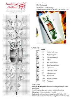


© Copyright 2026