
Ast 448 Set 1: CMB Statistics
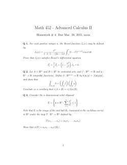
Ast 448 Set 1: CMB Statistics Wayne Hu Planck Power Spectrum B-modes: Auto & Cross CMB Blackbody • COBE FIRAS revealed a blackbody spectrum at T = 2.725K (or cosmological density Ωγ h2 = 2.471 × 10⁻⁵ ) GHz 200 12 400 600 Bν (× 10–5) 10 8 error × 50 6 4 2 0 5 10 15 frequency (cm–1) 20 CMB Blackbody • CMB is a (nearly) perfect blackbody characterized by a phase space distribution function f= 1 eE/T − 1 ˆ , t) is observed at our position x = 0 where the temperature T (x, n and time t0 to be nearly isotropic with a mean temperature of T¯ = 2.725K • Our observable then is the temperature anisotropy ˆ , t0 ) − T¯ T (0, n Θ(ˆ n) ≡ T¯ • Given that physical processes essentially put a band limit on this function it is useful to decompose it into a complete set of harmonic coefficients Spherical Harmonics • Laplace Eigenfunctions ∇2 Y`m = −[l(l + 1)]Y`m • Orthogonal and complete Z m∗ m0 dˆ nY` (ˆ n)Y`0 (ˆ n) = δ``0 δmm0 X Y`m∗ (ˆ n)Y`m (ˆ n0 ) = δ(φ − φ0 )δ(cos θ − cos θ0 ) `m Generalizable to tensors on the sphere (polarization), modes on a curved FRW metric • Conjugation Y`m∗ = (−1)m Y`−m Multipole Moments • Decompose into multipole moments X n) Θ(ˆ n) = Θ`m Y`m (ˆ `m • So Θ`m is complex but Θ(ˆ n) real: X ∗ n) Θ (ˆ n) = Θ∗`m Y`m∗ (ˆ `m = X Θ∗`m (−1)m Y`−m (ˆ n) `m = Θ(ˆ n) = X n) = Θ`m Y`m (ˆ `m so m and −m are not independent Θ∗`m = (−1)m Θ` −m X `−m Θ`−m Y`−m (ˆ n) N -pt correlation • Since the fluctuations are random and zero mean we are interested in characterizing the N -point correlation X X mn 1 hΘ(ˆ n1 ) . . . Θ(ˆ nn )i = hΘ`1 m1 . . . Θ`n mn iY`m (ˆ n ) . . . Y nn ) 1 `n (ˆ 1 `1 ...`n m1 ...mn • Statistical isotropy implies that we should get the same result in a rotated frame X m0 m ` R[Y` (ˆ n)] = Dm0 m (α, β, γ)Y` (ˆ n) m0 where α, β and γ are the Euler angles of the rotation and D is the Wigner function (note Y`m is a D function) X `1 `n hΘ`1 m1 . . . Θ`n mn i = hΘ`1 m01 . . . Θ`n m0n iDm . . . D 0 mn m0n 1m m01 ...m0n 1 N -pt correlation • For any N -point function, combine rotation matrices (group multiplication; angular momentum addition) and orthogonality X `1 `1 (−1)m2 −m Dm D −m2 −m = δm1 m2 1m m • The simplest case is the 2pt function: hΘ`1 m1 Θ`2 m2 i = δ`1 `2 δm1 −m2 (−1)m1 C`1 where C` is the power spectrum. Check X `1 `2 m01 0 0 δ`1 `2 δm1 −m2 (−1) C`1 Dm D = 0 m2 m0 1m 1 m01 m02 2 X `2 m01 `1 m1 = δ`1 `2 C`1 (−1) Dm1 m0 Dm = δ δ (−1) C`1 0 ` ` m −m 1 2 1 2 2 −m m01 1 1 N -pt correlation • Using the reality of the field hΘ∗`1 m1 Θ`2 m2 i = δ`1 `2 δm1 m2 C`1 . • If the statistics were Gaussian then all the N -point functions would be defined in terms of the products of two-point contractions, e.g. hΘ`1 m1 Θ`2 m2 Θ`3 m3 Θ`4 m4 i = δ`1 `2 δm1 m2 δ`3 `4 δm3 m4 C`1 C`3 + perm. • More generally we can define the isotropy condition beyond Gaussianity, e.g. the bispectrum hΘ`1 m1 . . . Θ`3 m3 i = `1 `2 `3 m1 m2 m3 ! B`1 `2 `3 CMB Temperature Fluctuations w quadrupole, octupole; C(θ); alignment; hemisphere • Angular Power Spectrum Angular Scale 90 6000 2 0.5 0.2 l(l+1)C l /2π (µK2 ) 5000 Model WMAP CBI ACBAR 4000 3000 2000 1000 0 10 40 100 200 400 Multipole moment (l) 800 1400 2 Why ` C`/2π? • Variance of the temperature fluctuation field XX m m0 ∗ ∗ n) n)Y`0 (ˆ hΘ(ˆ n)Θ(ˆ n)i = hΘ`m Θ`0 m0 iY` (ˆ `m `0 m0 = X ` = C` X m X 2` + 1 ` n) n)Y`m∗ (ˆ Y`m (ˆ 4π C` via the angle addition formula for spherical harmonics • For some range ∆` ≈ ` the contribution to the variance is hΘ(ˆ n)Θ(ˆ n)i`±∆`/2 `2 2` + 1 C` ≈ C` ≈ ∆` 4π 2π • Conventional to use `(` + 1)/2π for reasons below Cosmic Variance • We only have access to our sky, not the ensemble average • There are 2` + 1 m-modes of given ` mode, so average X 1 Θ∗`m Θ`m Cˆ` = 2` + 1 m • hCˆ` i = C` but now there is a cosmic variance σC2 ` h(Cˆ` − C` )(Cˆ` − C` )i hCˆ` Cˆ` i − C`2 = = 2 C` C`2 • For Gaussian statistics σC2 ` X 1 ∗ ∗ h Θ Θ Θ = `m `m0 Θ`m0 i − 1 `m 2 2 (2` + 1) C` mm0 X 1 2 = (δmm0 + δm−m0 ) = 2 (2` + 1) mm0 2` + 1 Cosmic Variance • Note that the distribution of Cˆ` is that of a sum of squares of Gaussian variates • Distributed as a χ2 of 2` + 1 degrees of freedom • Approaches a Gaussian for 2` + 1 → ∞ (central limit theorem) • Anomalously low quadrupole is not that unlikely • σC` is a useful quantification of errors at high ` • Suppose C` depends on a set of cosmological parameters ci then we can estimate errors of ci measurements by error propagation −1 Fij = Cov (ci , cj ) = ∂C`0 Cov (C` , C`0 ) ∂ci ∂cj X ∂C ``0 X (2` + 1) ∂C ∂C ` ` = 2 2C ∂ci ∂cj ` ` ` −1 Idealized Statistical Errors • Take a noisy estimator of the multipoles in the map ˆ `m = Θ`m + N`m Θ and take the noise to be statistically isotropic ∗ N`0 m0 i = δ``0 δmm0 C`N N hN`m • Construct an unbiased estimator of the power spectrum hCˆ` i = C` Cˆ` = l X 1 ˆ ∗`m Θ ˆ `m − C`N N Θ 2` + 1 m=−l • Covariance in estimator 2 (C` + C`N N )2 δ``0 Cov(C` , C`0 ) = 2` + 1 Incomplete Sky • On a small section of sky, the number of independent modes of a given ` is no longer 2` + 1 • As in Fourier analysis, there are two limitations: the lowest ` mode that can be measured is the wavelength that fits in angular patch θ 2π ; `min = θ modes separated by ∆` < `min cannot be measured independently • Estimates of C` covary on a scale imposed by ∆` < `min • Crude approximation: account only for the loss of independent modes by rescaling the errors rather than introducing covariance 2 (C` + C`N N )2 δ``0 Cov(C` , C ) = (2` + 1)fsky `0 Time Ordered Data • Beyond idealizations like |Θ`m |2 type C` estimators and fsky mode counting, basic aspects of data analysis are useful even for theorists • Starting point is a string of “time ordered” data coming out of the instrument (post removal of systematic errors, data cuts) • Begin with a model of the time ordered data as (implicit summation or matrix operation) d = PΘ + n where the elements of the vector Θi denotes pixelized positions indexed by i and the element of the data dt is a time ordered stream indexed by t. • Noise nt is drawn from distribution with known power spectrum hnt nt0 i = Cd,tt0 Design Matrix • The design, pointing or projection matrix P is the mapping between pixel space and the time ordered data • Simplest incarnation: row with all zeros except one column which just says what point in the sky the telescope is pointing at that time 0 0 1 ... 0 1 0 0 ... 0 P= ... ... ... ... ... 0 0 1 ... 0 • If each pixel were only measured once in this way then the estimator of the map would just be the inverse of P • More generally encorporates differencing, beam, rotation (for polarization) and unequal coverage of pixels Maximum Likelihood Mapmaking • What is the best estimator of the underlying map Θi ? • Likelihood function: the probability of getting the data given the theory Ltheory (data) ≡ P [data|theory]. In this case, the theory is the vector of pixels Θ. 1 1 t −1 √ exp − (d − PΘ) C LΘ (d) = d (d − PΘ) . N /2 t 2 (2π) det Cd • Bayes theorem says that P [Θ|d], the probability that the temperatures are equal to Θ given the data, is proportional to the likelihood function times a prior P (Θ), taken to be uniform P [Θ|d] ∝ P [d|Θ] ≡ LΘ (d) Maximum Likelihood Mapmaking • Maximizing the likelihood of Θ is simple since the log-likelihood is quadratic – it is equivalent to minimizing the variance of the estimator • Differentiating the argument of the exponential with respect to Θ and setting to zero leads immediately to the estimator ˆ = Pt C−1 d P) Θ (Pt C−1 d d ˆ = (Pt C−1 P)−1 Pt C−1 d , Θ d d which is unbiased ˆ = (Pt C−1 P)−1 Pt C−1 PΘ = Θ hΘi d d Maximum Likelihood Mapmaking • And has the covariance ˆ t i − ΘΘ ˆ t CN ≡ hΘΘ −t −t t −1 t −1 t −1 ˆ t P) − ΘΘ P(P C hdd iC P) P C = (Pt C−1 d d d d −t t −1 −1 t −t P) P(P C P) P C = (Pt C−1 d d d −1 P) = (Pt C−1 d The estimator can be rewritten using the covariance matrix as a renormalization that ensures an unbiased estimator ˆ = CN PC−1 d , Θ d • Given the large dimension of the time ordered data, direct matrix manipulation is unfeasible. A key simplifying assumption is the stationarity of the noise, that Cd,tt0 depends only on t − t0 (temporal statistical homogeneity) Foregrounds • Maximum likelihood mapmaking can be applied to the time streams of multiple observations frequencies Nν and hence obtain multiple maps • A cleaned CMB map can be obtained by modeling the maps as ˆ ν = Aν Θi + nν + f ν Θ i i i i where Aνi = 1 if all the maps are at the same resolution (otherwise, embed the beam as in the pointing matrix; fiν is the foreground model - e.g. a set of sky maps and a spectrum for each foreground, or more generally including a covariance matrix between frequencies due to varying spectral index • 5 foregrounds: synchrotron, free-free, radio pt sources, at low frequencies and dust and IR pt sources at high frequencies. Pixel Likelihood Function • The next step in the chain of inference is to go from the map to the power spectrum • In the most idealized form (no beam) we model X Θi = Θ`m Y`m (ni ) `m and using the angle addition formula X m ∗ Y`m (ni )Y`m (nj ) 2` + 1 ˆj) P` (ˆ ni · n = 4π with averages now including realizations of the signal ˆ iΘ ˆ j i ≡ CΘ,ij = CN,ij + CS,ij hΘ Pixel Likelihood Function • Pixel covariance matrix for the signal characterizes the sample variance of Θi through the power spectrum C` CS,ij ≡ hΘi Θj i = X 2` + 1 ` 4π ˆj) C` P` (ˆ ni · n • More generally the sky map is convolved with a beam and so the power spectrum is multiplied by the square of the beam transform • From the pixel likelihood function we can now directly use Bayes’ theorem to get the posterior probability of cosmological parameters c upon which the power spectrum depends 1 1 t −1 √ Lc (Θ) = exp − Θ CΘ Θ N /2 p 2 (2π) det CΘ where Np is the number of pixels in the map. Pixel Likelihood Function • Generalization of the Fisher matrix, curvature of the log Likelihood function ∂ 2 ln Lc (Θ) i Fab ≡ −h ∂ca ∂cb • Cramer-Rao theorem says that F−1 gives the minimum variance for an unbiased estimator of c. • Correctly propagates effects of pixel weights, noise - generalizes straightforwardly to polarization (E, B mixing etc) Power Spectrum • It is computationally convenient and sufficient at high ` to divide this into two steps: estimate the power spectrum Cˆ` and approximate the likelihood function for Cˆ` as the data and C` (c) as the model. • In principle we can just use Bayes’ theorem to get the maximum likelihood estimator Cˆ` and the joint posterior probability distribution or covariance • Although the pixel likelihood is Gaussian in the anisotropies Θi it is not in C` and so the “mapmaking” procedure above does not work Power Spectrum • MASTER approach is to use harmonic transforms on the map, mask and all • Masked pixels multiply the map in real space and convolve the multipoles in harmonic space - so these pseudo-C` ’s are convolutions on the true C` spectrum • Invert the convolution to form an unbiased estimator and propagate the noise and approximate the LC` (Cˆ` ) • Now we can use Bayes’ theorem with C` parameterized by cosmological parameters c to find the joint posterior distribution of c • Still computationally expensive to integrate likelihood over a multidimensional cosmological parameter space MCMC • Monte Carlo Markov Chain (MCMC) • Start with a set of cosmological parameters cm , compute likelihood • Take a random step in parameter space to cm+1 of size drawn from a multivariate Gaussian (a guess at the parameter covariance matrix) Cc (e.g. from the crude Fisher approximation or the covariance of a previous short chain run). Compute likelihood. • Draw a random number between 0,1 and if the likelihood ratio exceeds this value take the step (add to Markov chain); if not then do not take the step (add the original point to the Markov chain). Repeat. • Given Bayes’ theorem the chain is then a sampling of the joint posterior probability density of the parameters Parameter Errors • Can compute any statistic based on the probability distribution of parameters • For example, compute the mean and variance of a given parameter NM X 1 cm c¯i = NM m=1 i NM X 1 2 − c ¯ ) (cm σ (ci ) = i NM − 1 m=1 i 2 • Trick is in assuring burn in (not sensitive to initial point), step size, and convergence • Usually requires running multiple chains. Typically tens of thousands of elements per chain. Stokes Parameters • Specific intensity is related to quadratic combinations of the electric field. • Define the intensity matrix (time averaged over oscillations) hE E† i • Hermitian matrix can be decomposed into Pauli matrices 1 † P = E E = (Iσ 0 + Q σ 3 + U σ 1 − V σ 2 ) , 2 where σ0 = 1 0 0 1 , σ1 = 0 1 1 0 , σ2 = 0 −i i 0 , σ3 = 1 0 0 −1 • Stokes parameters recovered as Tr(σi P) • Choose units of temperature for Stokes parameters I → Θ Stokes Parameters • Consider a general plane wave solution E(t, z) = E1 (t, z)ˆ e1 + E2 (t, z)ˆ e2 E1 (t, z) = A1 eiφ1 ei(kz−ωt) E2 (t, z) = A2 eiφ2 ei(kz−ωt) • Explicitly: I = hE1 E1∗ + E2 E2∗ i = A21 + A22 Q = hE1 E1∗ − E2 E2∗ i = A21 − A22 U = hE1 E2∗ + E2 E1∗ i = 2A1 A2 cos(φ2 − φ1 ) V = −i hE1 E2∗ − E2 E1∗ i = 2A1 A2 sin(φ2 − φ1 ) so that the Stokes parameters define the state up to an unobservable overall phase of the wave Detection . • This suggests that abstractly there are two different ways to detect polarization: separate and difference orthogonal modes (bolometers I, Q) or correlate the separated components (U , V ). ε1 OMT g1 Q ε2 g2 U φ V • In the correlator example the natural output would be U but one can recover V by introducing a phase lag φ = π/2 on one arm, and Q by having the OMT pick out directions rotated by π/4. • Likewise, in the bolometer example, one can rotate the polarizer and also introduce a coherent front end to change V to U . Detection • Techniques also differ in the systematics that can convert unpolarized sky to fake polarization • Differencing detectors are sensitive to relative gain fluctuations • Correlation detectors are sensitive to cross coupling between the arms • More generally, the intended block diagram and systematic problems map components of the polarization matrix onto others and are kept track of through “Jones” or instrumental response matrices Edet = JEin Pdet = JPin J† where the end result is either a differencing or a correlation of the Pdet . Polarization • Radiation field involves a directed quantity, the electric field vector, which defines the polarization • Consider a general plane wave solution E(t, z) = E1 (t, z)ˆ e1 + E2 (t, z)ˆ e2 E1 (t, z) = ReA1 eiφ1 ei(kz−ωt) E2 (t, z) = ReA2 eiφ2 ei(kz−ωt) or at z = 0 the field vector traces out an ellipse E(t, 0) = A1 cos(ωt − φ1 )ˆ e1 + A2 cos(ωt − φ2 )ˆ e2 with principal axes defined by E(t, 0) = A01 cos(ωt)ˆ e01 − A02 sin(ωt)ˆ e02 so as to trace out a clockwise rotation for A01 , A02 > 0 Polarization . e2 • Define polarization angle ˆ01 = cos χˆ e1 + sin χˆ e2 e ˆ02 e e'2 χ = − sin χˆ e1 + cos χˆ e2 • Match e1 + sin χˆ e2 ] E(t, 0) = A01 cos ωt[cos χˆ − A02 cos ωt[− sin χˆ e1 + cos χˆ e2 ] = A1 [cos φ1 cos ωt + sin φ1 sin ωt]ˆ e1 + A2 [cos φ2 cos ωt + sin φ2 sin ωt]ˆ e2 e'1 E(t) e1 Polarization • Define relative strength of two principal states A01 = E0 cos β A02 = E0 sin β • Characterize the polarization by two angles A1 cos φ1 = E0 cos β cos χ, A1 sin φ1 = E0 sin β sin χ, A2 cos φ2 = E0 cos β sin χ, A2 sin φ2 = −E0 sin β cos χ Or Stokes parameters by I = E02 , Q = E02 cos 2β cos 2χ U = E02 cos 2β sin 2χ , V = E02 sin 2β • So I 2 = Q2 + U 2 + V 2 , double angles reflect the spin 2 field or headless vector nature of polarization Polarization Special cases • If β = 0, π/2, π then only one principal axis, ellipse collapses to a line and V = 0 → linear polarization oriented at angle χ If χ = 0, π/2, π then I = ±Q and U = 0 If χ = π/4, 3π/4... then I = ±U and Q = 0 - so U is Q in a frame rotated by 45 degrees • If β = π/4, 3π/4, then principal components have equal strength and E field rotates on a circle: I = ±V and Q = U = 0 → circular polarization • U/Q = tan 2χ defines angle of linear polarization and V /I = sin 2β defines degree of circular polarization Natural Light • A monochromatic plane wave is completely polarized I 2 = Q2 + U 2 + V 2 • Polarization matrix is like a density matrix in quantum mechanics and allows for pure (coherent) states and mixed states • Suppose the total Etot field is composed of different (frequency) components Etot = X Ei i • Then components decorrelate in time average D E XD E XD E Etot E†tot = Ei E†j = Ei E†i ij i Natural Light • So Stokes parameters of incoherent contributions add I= X i Ii Q= X i Qi U= X i Ui V = X i and since individual Q, U and V can have either sign: I 2 ≥ Q2 + U 2 + V 2 , all 4 Stokes parameters needed Vi Linear Polarization • Q ∝ hE1 E1∗ i − hE2 E2∗ i, U ∝ hE1 E2∗ i + hE2 E1∗ i. • Counterclockwise rotation of axes by θ = 45◦ √ √ 0 0 0 0 E1 = (E1 − E2 )/ 2 , E2 = (E1 + E2 )/ 2 • U∝ 0 0∗ hE1 E1 i − 0 0∗ hE2 E2 i, difference of intensities at 45◦ or Q0 • More generally, P transforms as a tensor under rotations and Q0 = cos(2θ)Q + sin(2θ)U U 0 = − sin(2θ)Q + cos(2θ)U or Q0 ± iU 0 = e∓2iθ [Q ± iU ] acquires a phase under rotation and is a spin ±2 object Coordinate Independent Representation • Two directions: orientation of polarization and change in amplitude, i.e. Q and U in the basis of the Fourier wavevector (pointing with angle φl ) for small sections of sky are called E and B components Z E(l) ± iB(l) = − dˆ n[Q0 (ˆ n) ± iU 0 (ˆ n)]e−il·ˆn Z = −e∓2iφl dˆ n[Q(ˆ n) ± iU (ˆ n)]e−il·ˆn . • For the B-mode to not vanish, the polarization must point in a direction not related to the wavevector - not possible for density fluctuations in linear theory • Generalize to all-sky: eigenmodes of Laplace operator of tensor Spin Harmonics • Laplace Eigenfunctions ∇2 ±2 Y`m [σ 3 ∓ iσ 1 ] = −[l(l + 1) − 4]±2 Y`m [σ 3 ∓ iσ 1 ] • Spin s spherical harmonics: orthogonal and complete Z ∗ dˆ ns Y`m (ˆ n)s Y`0 m0 (ˆ n) = δ``0 δmm0 X ∗ n)s Y`m (ˆ n0 ) = δ(φ − φ0 )δ(cos θ − cos θ0 ) s Y`m (ˆ `m where the ordinary spherical harmonics are Y`m = 0 Y`m • Given in terms of the rotation matrix r 2` + 1 ` m D−ms (αβ0) s Y`m (βα) = (−1) 4π Statistical Representation • All-sky decomposition [Q(ˆ n) ± iU (ˆ n)] = X [E`m ± iB`m ]±2 Y`m (ˆ n) `m • Power spectra ∗ E`m i = δ``0 δmm0 C`EE hE`m ∗ B`m i = δ``0 δmm0 C`BB hB`m • Cross correlation hΘ∗`m E`m i = δ``0 δmm0 C`ΘE others vanish if parity is conserved Inhomogeneity vs Anisotropy • Θ is a function of position as well as direction but we only have access to our position • Light travels at the speed of light so the radiation we receive in ˆ was (η0 − η)ˆ direction n n at conformal time η • Inhomogeneity at a distance appears as an anisotopy to the observer • We need to transport the radiation from the initial conditions to the observer • This is done with the Boltzmann or radiative transfer equation • In the absence of scattering, emission or absorption the Boltzmann equation is simply Df =0 Dt Last Scattering vb k Doppler effect l<kD* D* acoustic pe ies secondar aks observer ∫dD jl(kD) ng su ra ce iz a ti o n l≈kD* l • Shell radius is distance from the observer to recombination: called the last scattering surface *) po • Angular distribution of radiation is the 3D temperature field projected onto a shell - surface of last scattering jl'( jl(kD*) . da m pin g and at s t las er • Take the radiation distribution at last scattering to also be described by an isotropic temperature fluctuation field Θ(x) Integral Solution to Radiative Transfer Sν Iν(τ) Iν(0) τ 0 τ' • Formal solution for specific intensity Iν = 2hν 3 f /c2 Iν (0) = Iν (τ )e −τ Z + τ 0 0 −τ 0 dτ Sν (τ )e 0 • Specific intensity Iν attenuated by absorption and replaced by source function, attenuated by absorption from foreground matter • Θ satisfies the same relation for a blackbody Angular Power Spectrum • Take recombination to be instantaneous: dτ e−τ = dDδ(D − D∗ ) and the source to be the local temperature inhomogeneity Z Θ(ˆ n) = dD Θ(x)δ(D − D∗ ) where D is the comoving distance and D∗ denotes recombination. • Describe the temperature field by its Fourier moments Z d3 k ik·x Θ(x) = Θ(k)e (2π)3 • Note that Fourier moments Θ(k) have units of volume k −3 • 2 point statistics of the real-space field are translationally and rotationally invariant • Described by power spectrum Spatial Power Spectrum • Translational invariance hΘ(x0 )Θ(x)i = hΘ(x0 + d)Θ(x + d)i Z d3 k d3 k 0 ∗ 0 ik·x−ik0 ·x0 hΘ (k )Θ(k)ie (2π)3 (2π)3 Z d3 k d3 k 0 ∗ 0 ik·x−ik0 ·x0 +i(k−k0 )·d hΘ (k )Θ(k)ie = (2π)3 (2π)3 So two point function requires δ(k − k0 ); rotational invariance says coefficient depends only on magnitude of k not its direction hΘ(k)∗ Θ(k0 )i = (2π)3 δ(k − k0 )PT (k) Note that Θ(k), δ(k − k0 ) have units of volume and so PT must have units of volume Dimensionless Power Spectrum • Variance Z d3 k PT (k) 3 (2π) 2 σΘ ≡ hΘ(x)Θ(x)i = Z 2 Z k dk dΩ = PT (k) 2 2π 4π Z k3 = d ln k 2 PT (k) 2π • Define power per logarithmic interval 3 k PT (k) 2 ∆T (k) ≡ 2π 2 • This quantity is dimensionless. Angular Power Spectrum • Temperature field d3 k ˆ ik·D∗ n Θ(k)e Θ(ˆ n) = (2π)3 P • Multipole moments Θ(ˆ n) = `m Θ`m Y`m Z • Expand out plane wave in spherical coordinates e ikD∗ ·ˆ n = 4π X ∗ i` j` (kD∗ )Y`m (k)Y`m (ˆ n) `m • Angular moment Z Θ`m = d3 k ` ∗ Θ(k)4πi j (kD )Y ` ∗ `m (k) 3 (2π) Angular Power Spectrum • Power spectrum Z 3 d k 2 `−`0 ∗ ∗ 0 (kD∗ )Y`m (k)Y 0 0 (k)PT (k) 0 0 (4π) i j (kD )j hΘ`m Θ` m i = ` ∗ ` `m (2π)3 Z = δ``0 δmm0 4π d ln k j`2 (kD∗ )∆2T (k) with R∞ 0 j`2 (x)d ln x = 1/(2`(` + 1)), slowly varying ∆2T • Angular power spectrum: 4π∆2T (`/D∗ ) 2π C` = = ∆2T (`/D∗ ) 2`(` + 1) `(` + 1) • Not surprisingly, a relationship between `2 C` /2π and ∆2T at ` 1. By convention use `(` + 1) to make relationship exact • This is a property of a thin-shell isotropic source, now generalize. Generalized Source . • For example, if the emission surface is moving with respect to the observer then radiation has an intrinsic dipole pattern at emission θ • More generally, we know the Y`m ’s are a complete angular basis and plane waves are complete spatial basis • Local source distribution decomposed into plane-wave modulated multipole moments r 4π (m) ` Y`m (ˆ n) exp(ik · x) S` (−i) 2` + 1 ˆ where prefactor is for convenience when fixing zˆ = k Generalized Source • So general solution is for a single source shell is r X (m) 4π ` ˆ) Θ(ˆ n) = S` (−i) Y`m (ˆ n) exp(ik · D∗ n 2` + 1 `m and for a source that is a function of distance r Z X (m) 4π ` −τ Θ(ˆ n) = dDe S` (D)(−i) Y`m (ˆ n) exp(ik · Dˆ n) 2` + 1 `m • Note that unlike the isotropic source, we have two pieces that ˆ depend on n • Observer sees the total angular structure X 0 m ikD∗ ·ˆ n ` m0 ∗ m0 Y` (ˆ n)e = 4π i j`0 (kD∗ )Y`0 (k)Y`0 (ˆ n)Y`m (ˆ n) `0 m0 Generalized Source • We extract the observed multipoles by the addition of angular m0 momentum Y`0 (ˆ n)Y`m (ˆ n) → YLM (ˆ n) • Radial functions become linear sums over j` with the recoupling (Clebsch-Gordan) coefficients • These radial weight functions carry important information about how spatial fluctuations project onto angular fluctuations - or the sharpness of the angular transfer functions • Same is true of polarization - source is Thomson scattering • Polarization has an intrinsic quadrupolar distribution, recoupled by orbital angular momentum into fine scale polarization anisotropy • Formal integral solution to the Boltzmann or radiative transfer equation • Source functions also follow from the Boltzmann equation Polarization Basis • Define the angularly dependent Stokes perturbation ˆ , η), Θ(x, n ˆ , η), Q(x, n ˆ , η) U (x, n • Decompose into normal modes: plane waves for spatial part and spherical harmonics for angular part r 4π m ` ˆ ) ≡ (−i) Y`m (ˆ n) exp(ik · x) G` (k, x, n 2` + 1 r 4π m ` m ˆ G (k, x, n ) ≡ (−i) Y n) exp(ik · x) ±2 ` ±2 ` (ˆ 2` + 1 • In a spatially curved universe generalize the plane wave part ˆ • For a single k mode, choose a coordinate system zˆ = k Normal Modes • Temperature and polarization fields Z d3 k X (m) m Θ` G` 3 (2π) `m Z d3 k X (m) (m) m ± iB ] G [E ±2 ` ` (2π)3 `m ` ˆ , η) = Θ(x, n ˆ , η) = [Q ± iU ](x, n • For each k mode, work in coordinates where k k z and so m = 0 represents scalar modes, m = ±1 vector modes, m = ±2 tensor modes, |m| > 2 vanishes. Since modes add incoherently and Q ± iU is invariant up to a phase, rotation back to a fixed coordinate system is trivial. Liouville Equation • In absence of scattering, the phase space distribution of photons in each polarization state a is conserved along the propagation path • Rewrite variables in terms of the photon propagation direction ˆ , so fa (x, n ˆ , q, η) and q = qn D ˆ , q, η) = 0 = fa (x, n Dη ∂ dx ∂ dˆ n ∂ dq ∂ + · + · + · ˆ ∂η dη ∂x dη ∂ n dη ∂q fa • For simplicity, assume spatially flat universe K = 0 then ˆ dη dˆ n/dη = 0 and dx = n ∂ ˙ ˆ · ∇fa + q˙ fa = 0 fa + n ∂q • The spatial gradient describes the conversion from inhomogeneity to anisotropy and the q˙ term the gravitational sources. Geometrical Projection • Main content of Liouville equation is purely geometrical and describes the projection of inhomogeneities into anisotropies • Spatial gradient term hits plane wave: r 4π 0 ik·x ik·x ˆ · ∇e n)eik·x kY1 (ˆ n = iˆ n · ke =i 3 • Dipole term adds to angular dependence through the addition of angular momentum r m κ κm 4π 0 m `+1 ` m m Y1 Y` = p Y`−1 +p Y`+1 3 (2` + 1)(2` − 1) (2` + 1)(2` + 3) √ m where κ` = `2 − m2 is given by Clebsch-Gordon coefficients. Temperature Hierarchy • Absorb recoupling of angular momentum into evolution equation for normal modes m m κ`+1 (m) κ` (m) (m) (m) (m) ˙ Θ`−1 − Θ`+1 − τ˙ Θ` + S` Θ` = k 2` + 1 2` + 3 (m) where S` are the gravitational (and later scattering sources; added scattering suppression of anisotropy) • An originally isotropic ` = 0 temperature perturbation will eventually become a high order anisotropy by “free streaming” or simple projection • Original CMB codes solved the full hierarchy equations out to the ` of interest. Integral Solution • Hierarchy equation simply represents geometric projection, exactly as we have seen before in the projection of temperature perturbations on the last scattering surface • In general, the solution describes the decomposition of the source (m) S` with its local angular dependence as seen at a distance D. • Proceed by decomposing the angular dependence of the plane wave X p ik·x ` n) e = (−i) 4π(2` + 1)j` (kD)Y`0 (ˆ ` • Recouple to the local angular dependence of Gm ` X p (m) m ` G`s = (−i) 4π(2` + 1)α`s ` (kD)Y`m (ˆ n) ` Integral Solution • Projection kernels: (m=0) (m=0) α`s =1` ≡ j`0 α`s =0` ≡ j` • Integral solution: (m) Θ` (k, η0 ) 2` + 1 η0 Z = −τ dηe 0 X (m) (m) S`s α`s ` (k(η0 − η)) `s • Power spectrum: Z C` = 4π (m)∗ (m) dk k 3 X hΘ` Θ` i k 2π 2 m (2` + 1)2 • Integration over an oscillatory radial source with finite width suppression of wavelengths that are shorter than width leads to reduction in power by k∆η/` in the “Limber approximation” Polarization Hierarchy • In the same way, the coupling of a gradient or dipole angular momentum to the spin harmonics leads to the polarization hierarchy: m 2 κ` m 2 κ`+1 2m (m) (m) (m) (m) B` − E`+1 − τ˙ E` + E` 2` − 1 `(` + 1) 2` + 3 m m κ 2m 2 2 κ` (m) (m) (m) (m) (m) =k B`−1 + E` − `+1 B`+1 − τ˙ B` + B` 2` − 1 `(` + 1) 2` + 3 (m) E˙ ` = k (m) B˙ ` (m) E`−1 − p where = (`2 − m2 )(`2 − 4)/`2 is given by the Clebsch-Gordon coefficients and E, B are the sources (scattering only). m 2 κ` • Note that for vectors and tensors |m| > 0 and B modes may be (m) generated from E modes by projection. Cosmologically B` = 0 Polarization Integral Solution • Again, we can recouple the plane wave angular momentum of the source inhomogeneity to its local angular dependence directly (m) E` (k, η0 ) = 2` + 1 (m) B` (k, η0 ) = 2` + 1 Z Z η0 0 η0 0 (m) (m) dηe−τ E`s `s ` (k(η0 − η)) (m) (m) dηe−τ E`s β`s ` (k(η0 − η)) • Power spectrum XY = ΘΘ, ΘE, EE, BB: Z (m)∗ (m) 3 X dk k hX Y` i XY ` C` = 4π k 2π 2 m (2` + 1)2 • We shall see that the only sources of temperature anisotropy are ` = 0, 1, 2 and polarization anisotropy ` = 2 ˆ there are only m = 0, ±1, ±2 or scalar, • In the basis of zˆ = k vector and tensor components Polarization Sources θ 0 π/2 π l=2, m=0 0 π/2 0 π/2 0 π/2 π 3π/2 2π π 3π/2 2π π 3π/2 2π φ θ 0 π/2 l=2, m=1 π φ θ 0 l=2, m=2 π/2 π φ Polarization Transfer • A polarization source function with ` = 2, modulated with plane wave orbital angular momentum • Scalars have no B mode contribution, vectors mostly B and tensor comparable B and E (a) Polarization Pattern (b) Multipole Power Scalars 1.0 E 0.5 π/2 Vectors θ 1.0 B 0.5 1.0 Tensors . π/2 0.5 0 π/4 φ π/2 10 l 100 Polarization Transfer • Radial mode functions characterize the projection from k → ` or inhomogeneity to anisotropy • Compared to the scalar T monopole source: scalar T dipole source very broad tensor T quadrupole, sharper scalar E polarization, sharper tensor E polarization, broad tensor B polarization, very broad • These properties determine whether features in the k-mode spectrum, e.g. acoustic oscillations, intrinsic structure, survive in the anisotropy


© Copyright 2026