
Recommended Practices for
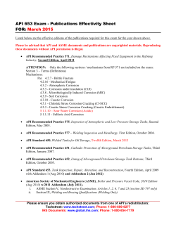
This document is not an API Standard; it is under consideration within an API technical committee but has not received all
approvals required to become an API Standard. It shall not be reproduced or circulated or quoted, in whole or in part, outside
of API committee activities except with the approval of the Chairman of the committee having jurisdiction and staff of the API
Standards Dept. Copyright API. All rights reserved.
API 19B, Section 3
3
3.1
Evaluation of Perforator Systems at Elevated Temperature Conditions
INTRODUCTION
The purpose of this test is to evaluate hollow carrier perforating systems at elevated temperature and atmospheric
pressure. Systems employing any type explosive may be evaluated by this method. The test is conducted at
temperature, with atmospheric pressure external to the gun to evaluate explosive system reliability, and utilizing
steel as the recommended, but not required, target material. Customer requirements may dictate that alternate
target materials be utilized, including concrete, rock, or other materials. Separate tests are conducted at
temperature, pressure, and time to verify the operational rating of the system. This section is intended as a
procedure to be followed for this testing.
3.2
REFERENCE DATA
A reference system test shall be conducted at atmospheric pressure and ambient temperature employing the
recommended steel target and the test described herein. However, alternate targets are allowed in Section 3 testing
as long as they can be compared back to reference performance tests which used the same type of target.
3.3
RECOMMENDED TEST TARGET
Tests are recommended to be conducted with a laminated target consisting of mild-steel (ASTM A36 or similar) flat
3
plates, 1 inch thick with a faceplate /8 inch thick. Cross sectional area of the plates shall be chosen for repeatable
data collection and may require scaling to appropriate dimensions to fit different sizes of gun systems, particularly
those with small diameter and close phasings and/or shot densities. Typical target configuration is shown in Figure
8. The target thickness for steel targets must be at least 0.5 inch greater than the average penetration depth
recorded.
Alternate steel materials may be used, such as those with higher strengths and tighter specifications than ASTM
A36 or similar. Moreover concrete or rock targets may be used when conducting Section 3 tests. Whenever
concrete is used, the recommended mixture is that of the target described in Section 1.
The two key aspects for selection of test target materials are: (1) the same type of material shall be used to conduct
both the reference test and the heated performance test, and (2) the temperature of the target during firing of the
heated performance test shall be at ambient temperature so that results can be compared directly to the reference
test.
In those instances where target construction requires the heated performance test be fired into heated targets, then
cross-correlation data shall be generated to show the difference in results when using heated targets versus targets
at ambient temperature.
3.4
PERFORATING SYSTEM SELECTION
The perforating system to be tested shall consist of the gun associated hardware, and firing head. Production
equipment (or specially modified hardware to the same specification) shall be utilized, including gun body, adapters,
transfer subs, and explosive components. The free volume to explosive load ratio must be the same or less than a
fully loaded field configuration gun: or previously established in a separate test by firing a minimum of one charge
after holding at time and temperature at an equal or lower free volume to explosive load ratio for this explosive. A
minimum of three such tests shall be conducted. For tubing conveyed systems, at least one transfer must be
demonstrated on the same or a separate test utilizing a production transfer sub. At least one charge shall be fired
subsequent to the transfer. For wireline conveyed systems, any electrical or mechanical switches shall be included if
recommended by the service company for this application, unless previously qualified in a separate test.
This document is not an API Standard; it is under consideration within an API technical committee but has not received all
approvals required to become an API Standard. It shall not be reproduced or circulated or quoted, in whole or in part, outside
of API committee activities except with the approval of the Chairman of the committee having jurisdiction and staff of the API
Standards Dept. Copyright API. All rights reserved.
3.5
CHARGE SELECTION AND AGING
The required number of charges shall be samples taken uniformly from a minimum production run of 300 charges
and packaged in the manufacturing/service company’s standard shipping containers. These charges shall be stored
for a minimum of four weeks prior to testing to allow some aging to occur.
3.6
GUN CONFIGURATION
Hollow carrier perforating guns must have pressure-tight enclosures on both ends and must be sealed during full
duration of the test.
3.7
CLEARANCE
When conducting tests using the recommended laminated steel targets, the gun-to-target clearance for all
perforating systems shall be zero inches from the outside diameter of the gun body. When using alternate target
geometries such as Section 1 concrete targets, the gun-to-target clearance shall be consistent between the
reference test and the heated performance test.
3.8
NUMBER OF SHOTS
For statistical purposes a minimum of six shots shall be fired in each gun tested.
3.9
TEMPERATURE ENVIRONMENT
Tests shall be conducted at elevated temperature and atmospheric pressure using the following procedures:
The Section 3 test methodology can take two general forms:
3.9.1 Method A: The perforating system under test is heated for the prescribed time and temperature and then the
firing attempt is made while the system is still at temperature. Using this method, functioning of the ballistic train is
confirmed along with a measure of charge performance while the system is still hot.
Pros:
•
The test can be completed in one event.
•
Test artifacts related to a heating and cooling cycle of the ballistic train are avoided.
•
System performance at elevated temperature (for comparison to reference ambient temperature test) is
directly measured
Cons:
•
The testing infrastructure is significantly more complex since the tests must be conducted using remote
handling equipment for safety.
3.9.2 Method B: The perforating system under test is heated for the prescribed time and temperature and then
allowed to cool to ambient temperature before firing. Using this method, functioning of the ballistic train is confirmed
after one heating and cooling cycle (and while at ambient conditions) which represents a more demanding ballistictransfer situation than Method A. However, evaluation of charge performance is not as realistic as Method A due to
expansion and contraction of explosive interfaces between liners and cases during the heating and cooling cycle.
This artifact then necessitates charge performance be evaluated separately at elevated termperature using thermal
ovens and single-shot geometry.
Pros:
•
The testing infrastructure can be much simpler than that required for Method A, especially when testing at
extreme temperatures.
•
The explosive components have been exercised for one heating and cooling cycle; from a function
standpoint this is ballistically more demanding than firing at temperature without a heating and cooling cycle.
This document is not an API Standard; it is under consideration within an API technical committee but has not received all
approvals required to become an API Standard. It shall not be reproduced or circulated or quoted, in whole or in part, outside
of API committee activities except with the approval of the Chairman of the committee having jurisdiction and staff of the API
Standards Dept. Copyright API. All rights reserved.
Cons:
•
Charge performance may be affected by the heating and cooling cycle thereby necessitating a separate test
using thermal ovens and single-shot geometry to gather the data at temperature.
•
For comparison to the reference charge test, cross-correlation data may be required to show the difference
in results when using heated versus ambient temperature targets.
a. The shots shall be made at temperature (±10ûF) after the perforating system has been exposed to the rated
temperature for the rated time period. Timeframes for the various conveyance means presented below are
recommend, but not required.
i.
Wireline applications: 1 hr
ii.
Coil tubing applications: 10 hr
iii.
Tractor applications: 15hr
iv.
Tubing conveyed applications: 100 hr
b. The perforating system shall be brought to the rated elevated temperature at a maximum rate of six degrees per
minute.
c. Average temperature of the test assembly shall be controlled to ±10ûF during the exposure period. Fluctuations
out of this range are allowable if the time out of the envelope is less than 10% of the total exposure time. Actual
average temperature shall be reported.
d. The time at which to start the clock for soak time begins when the first of the two monitoring thermocouples
described in 3.11 reaches the target temperature.
3.10 TEST FLUID ENVIRONMENT
The reference test (refer to 3.2) and elevated temperature test shall be similarly conducted in air or an appropriate
liquid environment, at the option of the testing company. A continuous fluid media shall be used to transfer heat to
the gun.
3.11 TEMPERATURE MONITORING
The temperature of the outer surface of the perforating gun adjacent to the top and bottom shot shall be separately
monitored by intimate contact throughout the course of the test. The thermocouple shall be accurately shielded to
ensure accurate surface gun body temperature. Suitable thermal sensing and remote recording equipment shall be
used to obtain a permanent record of the temperature profile for the complete test. All equipment shall be calibrated
and certified on a regular basis.
This document is not an API Standard; it is under consideration within an API technical committee but has not received all
approvals required to become an API Standard. It shall not be reproduced or circulated or quoted, in whole or in part, outside
of API committee activities except with the approval of the Chairman of the committee having jurisdiction and staff of the API
Standards Dept. Copyright API. All rights reserved.
Figure 8—Schematic Illustration of Steel Target for Elevated Temperature Test
[Note: illustration is generic and target construction may require scaling as described in 3.3 to accommodate
different gun diameters, phasings, and shot densities.]
This document is not an API Standard; it is under consideration within an API technical committee but has not received all
approvals required to become an API Standard. It shall not be reproduced or circulated or quoted, in whole or in part, outside
of API committee activities except with the approval of the Chairman of the committee having jurisdiction and staff of the API
Standards Dept. Copyright API. All rights reserved.
3.12 TEST ASSEMBLY
The method used to mount the steel targets to the perforating system shall be at the option of the testing company.
3.13 DATA COLLECTION AND RECORDING
The following measurements shall be made for each perforating system evaluated:
a. Total depth of penetration.
b. Faceplate hole diameter when using laminated steel targets, or other appropriate hole diameter measurement
when alternate targets are used.
c. Faceplate hole roundness when using laminated steel targets, or other appropriate hole roundness measurement
when alternate targets are used.
d. Time/temperature profile record of the outer surface of the perforating gun adjacent to the top and bottom shot.
3.13.1 Total Depth
The total depth shall be measured as the distance from the inside faceplate of the target to the farthest point
penetrated by the shaped charge perforating system. The penetration shall be measured to the nearest 0.01 inch.
The data shall be expressed as a ratio of the average hot/cold penetration.
3.13.2 Faceplate Hole Diameter
3
The faceplate hole diameter shall be measured on the inside /8-inch faceplate of the target along the short and long
elliptical axes of the hole. Both the minimum and maximum shall be expressed as a ratio of the average hot/cold
faceplate diameter hole. Such measurements shall be made with a caliper, the arms of which will readily pass
through the faceplate perforation. Faceplate hole diameter shall be measured to the nearest 0.01 inch.
3.13.3 Faceplate Hole Roundness
The faceplate hole diameter roundness shall be reported as the average maximum faceplate hole diameter divided
by the average minimum faceplate hole diameter. This ratio shall be calculated for both hot and cold shots.
3.13.4 Extra Shots
The testing company may test more than the minimum number of charges to obtain a more accurate statistical
distribution of test results, but data from all charges tested in any test conducted under API RP 19B, Section 3, shall
be reported.
3.14 PRESSURE TESTING OF THE GUN SYSTEM
A separate test shall be made to verify the pressure/temperature/time rating of the gun system. No explosives are
required to be in the gun system at this time.
3.14.1 Test Requirements
The test must be made in a suitable pressure vessel with provisions for pressure, temperature. and time chart
recorders. Gauges should be calibrated and certified on a regular basis. Materials for the gun system are to satisfy
engineering design and quality control specifications as to metallurgy, chemical composition, physical properties,
and dimensional properties. Gun body length shall have a minimum unsupported section of eight diameters of
nominal outside diameter. If filler bars are used they must have a maximum outside diameter at least 0.25 inch
smaller than the inside diameter of the gun. Seal dimensions are to be adjusted to maximum extrusion gap for the
test unless all seal configurations represented in the system have been separately and identically qualified.
This document is not an API Standard; it is under consideration within an API technical committee but has not received all
approvals required to become an API Standard. It shall not be reproduced or circulated or quoted, in whole or in part, outside
of API committee activities except with the approval of the Chairman of the committee having jurisdiction and staff of the API
Standards Dept. Copyright API. All rights reserved.
3.14.2 Minimum Test Conditions
3.14.2.1 Pressure: At the adjusted pressure test value (±500 psi) (refer to 3.14.3) with a minimum test pressure of
1.05 times the operational pressure rating.
3.14.2.2 Temperature: At the operational temperature rating (±10ûF).
3.14.2.3 Duration: One hour at the adjusted pressure test value and operational temperature rating for gun bodies;
maximum time rating at adjusted pressure test value and operational temperature for seals.
3.14.3 Determination of Adjusted Pressure Test Value
Compute the collapse of the gun body to be actually tested utilizing those parameters required by recognized
engineering practice. Compute the collapse of the gun body at “minimum material conditions” (MMC) utilizing
specified physical and dimensional properties. Compute the adjusted test pressure as follows:
C A × Pr
PATV = ---------------C MMC
(3-1)
where
P ATV = Calculated adjusted pressure test value to which a specific gun sample is subjected that is equivalent to
worst case conditions (minimum material conditions of physical properties, dimensions, and seals),
taking into consideration the applicable manufacturing or service company’s safety factor, psi.
C A = Calculated collapse value (or failure) of an actual gun specimen to be evaluated based on its measured
(actual) physical properties, dimensions, and seals, psi. (For example, the calculated collapse value for
a specific gun specimen may be 24,500 psi, however, this value could drop as low as 21,000 psi under
minimum material conditions on other production runs.)
P r = Operational pressure rating, the maximum to which the gun should be subjected in field service, psi.
(This value is related to C MMC by the manufacturing or service company’s assigned safety factor. For
example, for a gun rated at 20,000 psi, the C MMC , is 21,000 psi, providing the safety factor is 1.05.)
C MMC = Calculated collapse value (or failure) of a hypothetical gun sample under worst case conditions or
“minimum material conditions” (MMC) of physical properties, dimensions, and seals, as permitted by
design specifications and engineering drawings, psi. (If C MMC for a gun sample with lowest permissible
tensile strength, minimum permissible wall thickness, and maximum permissible seal gap is calculated
to be 21,000 psi, it has an assigned operational pressure rating (P r ) of 20,000 psi providing the safety
factor is 1.05.)
Note: Using the information in the foregoing examples the adjusted pressure test value, PATV, would be calculated as follows:
C A × Pr
PATV = ---------------C MMC
24,500 × 20,000
PATV = --------------------------------------- = 23,333 psi
21,000
3.14.4 Alternate Procedure for Verification of Adjusted Pressure Test Value
Where the computed collapse value is deemed not reliable, a gun body or minimum of six expendable charge cases
shall be prepared and tested with materials taken uniformly from production run mill stock and verified or prepared to
meet minimum physical and dimensional properties. The gun body or expendable charge cases should be verified
or prepared to meet minimum material conditions on all dimensions by careful machining with reference to the
applicable engineering specifications. Tolerances for minimum material conditions shall be ±0.001 inch. The gun
This document is not an API Standard; it is under consideration within an API technical committee but has not received all
approvals required to become an API Standard. It shall not be reproduced or circulated or quoted, in whole or in part, outside
of API committee activities except with the approval of the Chairman of the committee having jurisdiction and staff of the API
Standards Dept. Copyright API. All rights reserved.
body or expendable charges shall then be tested at a minimum test pressure of 1.05 times the operational pressure
rating.
3.14.5 Disposition of Test Data
Details of test data and corresponding specifications and quality control documentation should be retained by the
manufacturer as long as the subject equipment is in field service.
3.15
Safety Aspects to Consider when Conducting Section 3 Tests
Safety is the responsibility of the organization conducting the test. The following aspects for consideration are
general in nature and are not all-inclusive. They are solely intended to raise awareness of potential hazards when
conducting Section 3 tests. Detailed requirements for operational safety and process safety reside with the
organization conducting the test.
3.15.1 Section 3 testing may involve pushing the limits of temperature/time relationships with explosives. In this
instance it is important to make provision for thermal decomposition that might accelerate uncontrollably to an
unplanned explosion. It is recommended that any perforating system that is or has been exposed to temperature
to be handled where possible with remote systems. For those instances where perforating systems cannot be
handled remotely, such as the actual downloading of a perforating system, then an appropriate cool down period
should be enacted. A recommended minimum time is eight (8) hours after cooling to ambient temperature.
Explosive systems containing HMX may warrant longer wait times if the thermal test exceeded 320 F (160 C) due
to the phase change of HMX to the delta polymorph.
3.15.2 After misfires, a recommended minimum wait time after cooling to ambient temperature is eight (8) hours
before approaching the perforating system for troubleshooting.
3.15.3 When hot oil systems are used for the heating medium, associated fire hazards and inhalation hazards must
be considered. Fire suppression systems are recommended for Section 3 test facilities that utilize hot oil, and may
also be appropriate when using other types of heating systems.
3.15.4 When conducting preliminary oven tests for shaped charges, a means for capturing the jet (or spoiling the jet)
should be provided.
3.15.5 If rock is used as the target material, it is important to consider the fluid which is used to saturate the pore
space. In this instance it would be appropriate to consider the use of non-flammable fluids or to even conduct the
test with dry pore space.


© Copyright 2026