
Installation Instructions
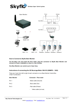
Installation Instructions
Thank you for purchasing the BLM2000 device. It truly is the New Concept in Beer Line Maintenance.
We at BIOQTECH would like you to familiarize yourself with the operation of the BLM2000.
Please take the time to read the following notes and installation instructions.
For an in-depth description on how the BLM2000 works, please refer to the ‘Specifications’.
Installation Procedure
The BLM2000 System can be comprised of any or all of the following:
•
•
•
•
•
•
•
Control Unit
Control Unit Mounting Bracket
Single Transponder
Double Transponder
Power Adapter
Power Connector Cable (1 meter)
Power Extension Cable (5 meters)
Prior to Installation
The BLM 2000 retards the growth of yeast and bacteria that inherently grow in beer lines, resulting in current
weekly or biweekly chemical cleaning cycles being extended to 8 to 10 weeks; only if the beer lines are
contamination free at the start of each new cleaning cycle.
To achieve the benefit of extended cleaning cycles, it is extremely important that before or immediately after
the installation of the BLM2000 System, all beer lines must be THOROUGHLY CHEMICALLY
CLEANED.
The BLM 2000 cannot remove yeast and bacteria already present in dirty beer lines by itself. Once the beer
line is free of contaminants, the BLM2000 System will maintain this level of cleanliness for as long as the
scheduled cleaning cycles are met and the BLM2000 System continues to operate.
Control Unit Installation
1
Locate a suitable mounting position for the Control Unit. It is advisable to choose a position close to the
beer lines that are going to be maintained by the BLM 2000. This position should be away from areas
common to spillage or excessive moisture (the BLM 2000 is an electronic device that is resistant to
moisture, but it is not waterproof) and a position where the Control Unit indicator lights are always
visible.
Holes for mounting screws
2
Using the supplied screws, attach the mounting bracket in the desired location. An alternative method of
attaching the mounting bracket is to use the supplied double-sided tape. However, the suggested
method is to attach the mounting bracket using screws.
3
After mounting the Control Unit bracket, attach the Control Unit to the bracket by guiding the 4 mounting
bracket arms into their respective slots located on the rear side of the Control Unit.
Removing Control Unit From Mounting Bracket
In a single motion, move the Control Unit in a vertical direction and pull the top of the unit outwards, thereby
releasing the top two mounting bracket arms first. The lower mounting bracket arms will release after the top
two mounting bracket arms release.
Transponder Installation
1
Each Transponder is attached to the outside wall of a beer line. The Transponder is affixed to the beer
line using the two supplied cable ties.
2
The Transponder can be positioned anywhere on the beer line. However, it is recommended that the
Transponder be attached to the trunk line after the wall bracket. This will ensure that there is no
operational interference and will protect the Transponder from damage. An alternative location is to
attach the Transponder to the drop line between the keg and the wall bracket. If an Empty Beer
Detector (EBD) or a Draft Foam Control (DFC) is being used, the Transponder must be located after
the EBD or DFC. These devices ensure that the beer line remains full and therefore will allow the BLM
to broadcast its audio signal.
3
In both cases, locate a position on the beer line as close as possible to wall bracket.
4
Each Transponder has a concave section, which is the contact position for the attachment of the beer
line. Position the Transponder onto the beer line, ensuring that the concave section of the Transponder
is contacting the beer line. Affix the two cable ties into the channelled sections of the Transponder and
secure firmly but not tight (if secured tight, the beer line will tend to be squashed.)
Transponder
Beer line
Transponder channel section
5
Connect the Transponder plug into the Control Unit.
Maximum Number of Beer Lines per Control Unit
The BLM 2000 has been engineered to accommodate a variety of beer dispensing configurations. Each
Control Unit can maintain up to a maximum of 3 beer lines. Therefore, a Control Unit is capable of maintaining
3 beer lines with 3 Transponders; one Transponder per beer line.
Transponder Configurations
A single Transponder uses a 3-pin plug, which is fitted into the position market ‘P1’ on the Control Unit. A
Double Transponder uses a 6-pin plug, which is fitted into the position marked ‘P2’ on the Control Unit.
Possible Configurations
Single Transponder connected to ‘P1’ only – Single Line Maintenance Operation
Double Transponder connected to ‘P2’ only – Double Line Maintenance Operation
Single and Double Transponders connected to ‘P1’ and ‘P2’ – Triple Line Maintenance Operation
Signal Reduction
Each Transponder emits an audio signal into the beer line. When using multiple Transponders, it is important
to ensure that Transponders are not positioned too close to each other. A recommended distance between
Transponders is 6 inches. If the Transponders are positioned close to each other, their respective signals will
interact and result in a reduction in the effectiveness of the BLM 2000 System.
6
Repeat steps 3 – 5 for installation of additional Transponders.
7
After all of the Transponders have been installed, gather all excess Transponder cable and bundle
neatly and out of the way.
Powering the BLM2000 System
Power Adapter
The Power Adapter is plugged into an AC outlet (either 100 VAC, 110 VAC, 220 VAC or 24 VAC, depending on
the country of operation.) The plug of the Power Adapter connects the 16 VAC output of the Power Adapter
into either the left or right hand side of the Control Unit.
Power for Multiple Beer Line Configurations
For beer dispensing configurations that have more than 3 beer lines, extra Control Units are needed. The
Control Units and Transponders can be installed in accordance with the above procedures. Power for the extra
Control Units is supplied from the Control Unit that is connected to the Power Adapter. The 16 VAC outlet from
this Control Unit supplies power to the other Control Units, via the use of one or more Power Connector
Cables.


© Copyright 2026