
OPERATION & MAINTENANCE MANUAL ™ SQUARE DRIVE SET HEX WRENCH SET
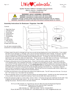
RSL-OM-1006 ™ OPERATION & MAINTENANCE MANUAL SQUARE DRIVE SET HEX WRENCH SET SALES, PARTS, REPAIR, CALLIBRATION, SERVICE and RENTAL: Western hemisphere: 2440 E. Pasadena Freeway, Pasadena, TX 77506, tel. 713-860-4200, toll free in USA: 1-800-895-3849 Eastern hemisphere: Bentley Road South, Darlaston, West Midlands, WS10 8LQ England, Phone: 0121 50 50 600 Optional - REPAIR and CALLIBRATION: 2010 Clermont Street, Antigo, WI 54409, tel: 715-627-5519, fax: 715-627-5544, toll free in USA: 1-800-569-6807 WEB SITE: http:/www.hydratight.com © Hydratight, 2006 TABLE OF CONTENTS PAGE SAFETY FIRST ----------------------------------------------------------------------------------------------------------------------------- 3 SECTION 1 – GENERAL BRIEF DESCRIPTION ------------------------------------------------------------------------------------------- 4 PREPARATION FOR OPERATION -------------------------------------------------------------------------- 4 SECTION 2 – GENERAL OPERATION INSTRUCTIONS GENERAL ---------------------------------------------------------------------------------------------------------- 5 TIGHTENING ----------------------------------------------------------------------------------------- ------------ 6 ALTERNATE – STUD ELONGATION METHOD ---------------------------------------------------------- 7 LOOSENING ------------------------------------------------------------------------------------------ ------------ 7 STUD/NUT SIZE CROSS REFERENCE -------------------------------------------------------------- ------ 10 PRESSURE/TORQUE CONVERSION CHART ------------------------------------------------------------ 11 SECTION 3 – RSL POWER HEAD WITH HEX WRENCH HEAD OPERATING INSTRUCTIONS GENERAL --------------------------------------------------------------------------------------------------------- 12 ASSEMBLY OF COMPONENTS ----------------------------------------------------------------------------- 13 SECTION 4 – RSL POWER HEAD WITH SQUARE DRIVE WRENCH HEAD OPERATING INSTRUCTIONS GENERAL --------------------------------------------------------------------------------------------------------- 15 ASSEMBLY OF COMPONENTS ----------------------------------------------------------------------------- 16 OPERATING RSL TOOL WITH THE SQUARE DRIVE WRENCH HEAD -------------------------- 16 SET–UP AND USE ---------------------------------------------------------------------------------------------- 17 SECTION 5 – PREVENTIVE MAINTENANCE RSL POWER HEAD --------------------------------------------------------------------------------------------- 18 RSL HEX AND SQUARE DRIVE WRENCH HEADS ---------------------------------------------------- 20 SECTION 6 – TROUBLESHOOTING ----------------------------------------------------------------------------------------------- 20 SECTION 7 – PARTS RSL POWER HEAD --------------------------------------------------------------------------------------------- 22 RSL HEX WRENCH HEAD PARTS LIST ------------------------------------------------------------------ 24 RSL SQUARE DRIVE WRENCH HEAD PARTS LIST -------------------------------------------------- 25 RSL REACTION ARM ASSEMBLY PARTS LIST -------------------------------------------------------- 26 SEAL KITS, PARTS LIST AND PLACEMENT GUIDE ---------------------------------------------------27 RSL TOOL DESCRIPTIONS ---------------------------------------------------------------------------------- 28 SECTION 8 – TENSION AND ELONGATION TENSION ---------------------------------------------------------------------------------------------------------- 29 TORQUE ------------------------------------------------------------------------------------------------ ---------- 29 ELONGATION --------------------------------------------------------------------------------------------------- 29 NOTES ---------------------------------------------------------------------------------------------------------------------------------- 30 SAFETY TAG -------------------------------------------------------------------------------------------------- ---------------------- 31 WARRANTY ------------------------------------------------------------------------------------------------------ ------------------- 32 This tool, when used in conjunction with the specified console and hoses, conforms with the requirements for CE Marking. Contact Hydratight for a list of approved components. 2 SAFETY FIRST RSL power tools enable the user to more easily accomplish bolting tasks with increased force, accuracy, and efficiency. It is due to the powered nature of the tools, with large forces generated from high pressure fluid/air and electricity applied to a variety of applications, that adherence to strict safety issues through the proper design and documented use of RSL tools. However, the user must accept the primary responsibility of safety when using RSL tools by reading, understanding, and complying with all operating instructions prior to and during operation. In a commitment to facilitate user understanding of all operating instructions, HYDRATIGHT offers (upon request) free videotapes and on-site training by a local representative. This manual and additional safety related services are designed to assist in the proper training for use and care of RSL tools and play a major role in preventing accidents and increasing safety. The following safety related operating instructions are documented in the manual and on a Safety Tag which should always be attached to the hydraulic pump when in use: Operator must read and understand all operating instructions prior to operations! In addition to this Manual, HYDRATIGHT offers (per request) videotapes and/or training on site by local representative. One-person operation recommended. Only one trained & competent person should control the operation of the tool. When two-person operation cannot be avoided a risk assessment must be undertaken that fully address the specific application, communication, & co-ordination of the tool operation between the two users, the person HOLDING the wrench should control operations. (Note: The person in control does not necessarily have the control pendant in his possession, but will give the commands to energize the console.) Do not use electric pump in explosive or wet environment! If electric pump is used, assure that grounding, power supply, and extension cord meet electrical code. Be aware of electrical hazards. Keep hands and fingers clear from pinch points! Pinch points are present around reaction area and in tight spaces. Set reaction properly! Improper reaction set-up and/or incorrect socket size will cause a concentration of stress that can make the tool, socket, or nut vulnerable to fracture. The common cause of socket breakage is cocking, a condition when socket fits over the bolt at an angle. Read this manual for examples of “how to” and “how not to” react, with and without Reaction Arm. High hydraulic pressure hazards, 10,000 psi (690 bar)! Use proper tools, hoses, fittings and protective equipment. Keep clear of leaking hydraulic fluid. Never exceed the maximum working pressure. Marking on the Wrench Head indicates maximum working pressure requirements. Wear safety glasses! Eye protection is necessary when working with or near the pressurized hydraulic system. Do not expose hoses to damaging conditions! Hose damage may result from mechanical, thermal, or chemical abuse and may release hydraulic fluid under pressure and cause injury. Disconnect all power supply before performing any maintenance! Maintain equipment in good working condition! Inspect for cracks, wear, and lubricate moving parts with SWEENEY 503 lubricant. Remove damaged equipment from service. Do not modify or subject any equipment or accessories to impact! Contact HYDRATIGHT for special tool applications or modifications. Unauthorized modification(s) may cause injury. To avoid possibility of falling objects in elevated areas, tool must be tied off to application area and reaction arm firmly attached to tool! Reaction arm must be firmly attached with locking devise provided as part of arm (Dialock, …) and can be further retained by safety cable. Contact Hydratight for Bulletin 116, which shows how to tie reaction arm to tool with cable. 3 SECTION 1 GENERAL FIGURE 1-1 RSL POWER HEAD BRIEF DESCRIPTION Ratcheting Slim Line (RSL) Tool is operated with 10000 psi (690 bar)* hydraulic pressure and is used to apply a specific tension to studs, bolts and cap screws by applying the proper torque value for a specific bolting material, size and type of lubrication. The Tool is also used to remove the tension when loosening is necessary. Caution! Do not modify any equipment or accessories. Contact HYDRATIGHT for special application(s) or modification(s). Unauthorized modification(s) may cause injury and damage, and will invalidate the warranty. The Tool is powered by a Console (hydraulic pump). The desired tension is achieved by precisely controlling the hydraulic fluid pressure produced by the Console and controlling the frictional force exerted between the studs and nuts. The hydraulic fluid pressure produced by the Consoles is accurate to 1%. The friction force is controlled by applying a lubricant with a known coefficient of friction to the threads and mating surfaces. PREPARATION FOR OPERATION Tools are inspected and tested at the HYDRATIGHT factory prior to shipment and should be ready for immediate use. However inspection of the Tool for damage and verification that all loose parts are included, is recommended. RSL Tool is offered in Seven standard models: (Example of RSL tool is shown in figure 1-1) * HYDRATIGHT offers full torque and limited torque RSL Wrench Heads –see marking on the housing. RSL2 with a maximum torque output of 1408 ft-lb. (1909 N-m) RSL4 with a maximum torque output of 3080 ft-lb. (4176 N-m) RSL6 with a maximum torque output of 5303 ft-lb. (7190 N-m) RSL8 with a maximum torque output of 7862 ft-lb. (10660 N-m) RSL14 with a maximum torque output of 11154 ft-lb. (15123 N-m) RSL20 with a maximum torque output of 18843 ft-lb. (25514 N-m) RSL30 with a maximum torque output of 28002 ft-lb. (37966 N-m) 4 SECTION 2 GENERAL OPERATING INSTRUCTIONS STEP 3 Select the Console, which best meets the requirements of the GENERAL application. The steps to be followed in selecting the correct Tool and Console for the Application and setting-up- the Tool are as follows: STEP 4. Connect the air or electrical power source, as applicable, to the Console. STEP 1 Determine the torque value 1. STEP 5. Connect the Twin Hoses to the Console. Each end of the hose will have one male and one female quick connect fitting. The Console will have like male/female quick connect fittings. Unscrew the locking collar on the female QD. Slide the outside slide ring back and snap the male and female together release the slide ring. Screw the locking collar back against the side ring. Slide Ring The torque value to be used for applying tension should be the value specified by the equipment manufacturer whenever it is available. For convenience, chart of torque values for common sizes of ASTM A193 Grades B7 and B16 studs and lubricants are shown in Figures 21 and 2-2. The torque values in the charts are based upon the following: Locking Collar Inch size studs are per ASTM A193, Grade B7 or B16, as applicable, with 10 UNC thread form on 3/4 inch studs, 9 UNC on 7/8 inch studs, 8 UNC on 1 inch studs, and 8 UN on 1 1/8 inch and larger studs. Inch size nuts are heavy hex per ASTM A194, Grade 2H. Metric size stud materials and thread forms are per IFI 500; Class 8.8 and nuts are per Class 9. Torque values listed in the charts will produce stud stress equal to 50% for B7 and 35% for B16 of the minimum yield strength of the specified materials, provided the threads and mating surfaces are in good condition and have been properly lubricated with the specified lubricant. STEP 6 Connect the Twin Hoses to RSL Tool, using the Quick Connect Fittings, as shown in Figure 2-2, before setting the tool on the application. Each end of the hose will have one male and one female quick connect fitting. The RSL Tool will have like male/female quick connect fittings. CAUTION: It the stud material, thread form, lubrication, or loading in your application is not the same as used to prepare the charts, do not use the charts. Contact Hydratight Customer Service for the bolting analysis of your application. 2. STEP 7. Set the torque value on the Console according to the instructions below for tightening or loosening, as applicable. STEP 8. Set the Tool on the nut and operate in accordance with the instructions in Section 3 or Section 4, Tool Operating Instructions. For other materials, thread forms, lubricants, or loading, contact Hydratight Customer Service to have the proper torque determined free of charge. The following information must be provided to determine the proper torque value for your application: a. Stud diameter at the threads (dimension a in Figure 2-1). b. Nut size across the flat (dimension b in Figure 2-1). c. Stud Grade (B7, B8, B16 etc.). d. Lubrication to be used on threads and mating surfaces and, if known, coefficient of friction of the lubricant. e. Desired tension (percentage of the yield strength of the stud material or tensile stress in the stud.) f. Threads per inch (dimension c in Figure 2-1) or inches per thread (dimension d in Figure 2-1) g. Extent of threading on the stud (full length or only at the ends). h. Stud solid or hollow; if hollow, inside diameter of the hole. i. Nut type (regular hex, heavy hex, special turntable diameter, etc.). b(AF) a d c NUT f e It the elongation of the stud or rotation of the nut methods are used to measure the tension in the studs, the following additional information must be provided: a. b. c. NUT Desired tension (elongation of the stud or rotation of the nut). If the threading is only at the ends, outside diameter of the stud between the nut faces (dimension e in Figure 2-1). Effective bolt length (dimension f in Figure 2-1). FIGURE 2-1 STUD AND NUT DIMENSION Note: Note the type of gasket material in use, as it may have an effect upon the tension required to achieve a good seal. STEP 2 Select the Tool, which best meets the requirements of the application. Note: When loosening, the Tool should be sized for torque values at least 1 1/2 and preferably 2 times of the tightening torque. 5 RSL TOOL TWIN LINE HOSES FIGURE 2-2 CONNECTING THE TWIN HOSES TO RSL TOOL TIGHTENING 1. Mark the correct tightening sequence on the studs in a clockwise direction with chalk as per diagram. For more explanation please read ASME-PPC-12000 or refer to the Hydratight Joint Integrity Assurance procedures. Marked up 8 Bolt Flange Criss-Cross Tightening Sequence Examples: 4 Bolt Flange 1-3-2-4 8 Bolt Flange 1-5-3-7-2-6-4-8 12 Bolt Flange 1-5-9-3-7-11-2-6-10-4-8-12 16 Bolt Flange 1-9-5-13-3-11-7-15-2-10-6-14-4-12-8-16 20 Bolt Flange 1-13-5-17-9-3-15-7-19-11-2-14-6-18-10-4-16-8-20-12 28 Bolt Flange 1-13-21-5-17-9-25-3-15-23-7-19-11-27-2-14-22-6-18-10-264-16-24-8-20-12-28 32 Bolt Flange 1-17-9-25-5-21-13-25-3-19-11-31-7-29-15-27-2-18-10-30-622-14-26-4-20-12-32-8-24-16-28 Note: Correct numbering of bolts should result in all odd numbered bolts around one side of the flange and all even numbered bolts around the other side. Determine the Torque Value for the stud or bolt to be tightened: - 1st,2nd,&3rd Stage Criss Cross Sequence First tightening stage should be limited to a maximum of 30% of the final Torque setting. Second tightening stage should be limited to a maximum of 60% of the final Torque setting. Third tightening stage should be carried out at the 100% Torque setting. On the Fourth and Final tightening stage, change from diagonal tightening to adjacent bolt-to-bolt tightening clockwise using the 100% Torque setting and chase around flange until nuts finally stop rotating. 4th & Final Stage Adjacent Bolt Sequence Note: First, second and third stages should be tightened using the criss cross tightening sequence and the fourth stage should be tightened using the adjacent clockwise bolt to bolt sequence as shown in the diagrams above. For more specific application based procedures please consult Hydratight Sweeny Joint Integrity Assurance procedures. *HYDRATIGHT offers Manual Control Pendant (standard) and Digital Control Pendant (option). FIGURE 2-3 FASTENING SEQUENCE FOR CIRCULAR FLANGES 6 BOLT SIZE (IN.) 3/4 7/8 1 1-1/8 1-1/4 1-3/8 1-1/2 1-5/8 1-3/4 1-7/8 2 2-1/8 2-1/4 2-3/8 2-1/2 2-3/4 3 3-1/4 3-1/2 3-3/4 4 4-1/4 4-1/2 NOTE: MINIMUM YIELD STRENGTH (PSI) BOLT TENSION (LBS.) 105000 105000 105000 105000 105000 105000 105000 105000 105000 105000 105000 105000 105000 105000 105000 95000 95000 95000 95000 95000 95000 75000 75000 17754 24495 32129 41873 52905 65226 78835 93733 109920 127395 146158 166210 187551 210180 234098 258580 310020 366124 426891 492321 562415 503030 565731 TORQUE FOR SPECIFIED LUBRICANT (FT-LBS.) 505 506 507 API SA2 503 504 SWEENEY SWEENEY SWEENEY SWEENEY SWEENEY f=.067 f=.085 f=.100 f=.110 f=.100 104 167 249 362 502 675 878 1124 1411 1744 2100 2529 3011 3552 4154 5024 6545 8346 10451 12880 15658 14850 17654 128 204 304 442 615 829 1082 1388 1746 2160 2611 3148 3751 4429 5184 6278 8189 10452 13099 16156 19655 18651 22185 147 234 349 508 709 958 1253 1608 2024 2507 3037 3663 4368 5160 6042 7324 9558 12207 15307 1887 22986 21819 25961 159 254 379 553 772 1043 1366 1755 2210 2739 3320 4007 4779 5648 6615 8020 10472 13377 16778 20707 25206 23931 28478 147 234 349 508 709 958 1253 1608 2024 2507 3037 3663 4368 5160 6042 7324 9558 12207 15307 1887 22986 21819 25961 f=.117 168 268 400 584 816 1103 1446 1858 2340 2901 3519 4247 5067 5989 7015 8508 11111 14196 17808 21982 26760 25409 30240 MACHINE OIL DRY STEEL ON STEEL f=.150 209 335 499 730 1023 1386 1820 2342 2953 3664 4455 5381 6424 7597 8903 10807 14124 18057 22664 27989 24088 32379 38548 f=.200 272 435 649 953 1337 1814 2387 3076 3883 4822 5874 7099 8480 10033 11764 14291 18689 23907 30022 37091 45190 42939 51134 503 – MOLYBDENUM DISULIFIED BASED (FUNCTIONAL EQUIVALENT C670, MOLY – COTE G PASTE) 504 – MOLYBDENUM LEAD OXIDE & GRAPHITE BASED (FUNCTIONAL EQUIVALENT C100) 505 – COPPER & GRAPHITE BASED (FUNCTIONAL EQUIVALENT N1000) 506 – NICKEL & GRAPHITE BASED (FUNCTIONAL EQUIVALENT NICKEL EASE N5000, NEVER – SEEZ NICKEL SPECIAL) 507 – COPPER & GRAPHITE BASED (FUNCTIONAL EQUIVALENT C5A, NEVER SEEZ) FIGURE 2-4 CHART OF TORQUE VALUES IN IMPERIAL UNITS FOR ASTM A-193 GRADE B7 WITH STUD STRESS EQUAL TO 50% OF MINIMUM YIELD STRENGTH ALTERNATE – STUD ELONGATION METHOD 3. If the stud elongation method of measuring tensioning is used, determine the torque value required to produce this amount of elongation in accordance with the instructions in Section 8, Tension, Torque and Elongation, or contact Hydratight Customer Service to have the value calculated free of charge. Then follow steps 1 through 7 above and measure the elongation of the studs. If the studs have not elongated fully, increase the torque value and continue to tighten the studs until the proper elongation is achieved. If the studs have elongated too far, loosen the studs until the proper elongation is achieved. To loosen the nut, place the RSL Tool to be used on the application in the loosening position (tool stroke extension will achieve a counter-clockwise rotation on the nut/bolt being worked). Depress and hold the Pendant Control button. 4. Move the Tool to the next nut to be loosened and repeat step 3 until all the nuts have been turned 1/8 turn. For Cameron BOP Bonnet bolts, loosen the bolts in a four post pattern, for other bolt patterns, the loosening can progress from nut to nut sequentially. Caution: When elongating fasteners, care should be taken to not over elongate the fastener, stud or flange as yielding of the material may result. Warning: If all the tension is removed from the first stud to be loosened at one time rather than loosening all the studs 1/8 turn, the tension in the remaining fastened studs will increase and ma result in damage to the studs or flange. LOOSENING 1. Adjust the Console to 10,000 psi (690 bar)* prior to mounting the RSL Tool on the nut by turning the Torque Control Knob clockwise until it stops. NOTE: HYDRATIGHT offers full-torque and limited-torque versions of RSL Hex (or square) Wrench Heads as a standard. Reduced torque (and size) is for limited space applications. For limited torque wrenches, maximum operating pressures vary. Refer to the maximum torque rating stamped on the wrench housing. To avoid wrench damage, do not exceed maximum torque rating. If max. torque rating is not stamped on the housing of the wrench, the Hex (or square) Wrench Head has no torque restrictions. 2. Liberally apply SWEENEY 501 penetrating oil to all the nuts in the application and let it set for a minimum of 5 minutes. Then setup the Tool on the nut to be loosened in accordance with the instructions in Section 3, Tooling Operation Instructions for RSL Tooling. 7 5. If the torque required to initially loosen the nuts was less than 150% of the tightening torque value, then the remaining tension may be fully removed in each nut sequentially. 6. If the torque required to initially loosen the nuts was greater than 150% of the tightening torque vale, repeat steps 3 and 4 on additional time for each nut so that the remaining tension may be fully removed in each nut sequentially. BOLT SIZE (IN.) 3/4 7/8 1 1-1/8 1-1/4 1-3/8 1-1/2 1-5/8 1-3/4 1-7/8 2 2-1/8 2-1/4 2-3/8 2-1/2 2-3/4 3 3-1/4 3-1/2 3-3/4 4 4-1/4 NOTE: MINIMUM YIELD STRENGT H (PSI) BOLT TENSION (LBS.) 105000 105000 105000 105000 105000 105000 105000 105000 105000 105000 105000 105000 105000 105000 105000 95000 95000 95000 95000 95000 95000 85000 12428 17147 22490 29311 27034 45658 55185 65613 76944 89176 102311 116347 131286 147126 163868 181000 217104 256287 298824 344625 393690 399071 STUD ELONGATION (INCHES PER INCH x 10-3) 1.225000 1.225000 1.225000 1.225000 1.225000 1.225000 1.225000 1.225000 1.225000 1.225000 1.225000 1.225000 1.225000 1.225000 1.225000 1.108330 1.108330 1.108330 1.108330 1.108330 1.108330 0.991667 TORQUE FOR SPECIFIED LUBRICANT (FT-LBS.) 503 504 505 506 507 SWEENEY SWEENEY SWEENEY SWEENEY® SWEENEY® f=.06 f=.085 f=.100 f=.110 f=.100 73 117 174 253 351 472 615 787 988 1220 1470 1770 2108 2487 2908 3517 4582 5842 7315 9016 10961 10395 89 142 212 309 430 580 758 972 1222 1512 1827 2203 2626 3100 3629 4395 5732 7316 9169 11309 13758 13056 102 164 244 356 496 670 877 1126 1417 1755 2125 2564 3058 3612 4230 5126 6691 8544 10714 13221 16090 15273 111 178 265 387 540 730 956 1228 1547 1917 2324 2804 3345 3953 4630 5614 7330 9364 11745 14495 17644 16752 102 164 244 356 496 670 877 1126 1417 1755 2125 2564 3058 3612 4230 5126 6691 8544 10714 13221 16090 15273 API SA2 MACHINE OIL DRY STEEL ON STEEL f=.117 117 188 280 408 571 772 1012 1300 1638 2030 2463 2973 3547 4192 4910 5955 7777 9937 12466 15387 18732 17786 f=.150 146 234 349 511 716 970 1274 1639 2067 2565 3119 3767 4497 5317 6232 7565 9886 12640 15865 19592 23861 22665 F=.200 190 305 454 667 936 1270 1671 2153 2718 3375 4112 4969 5936 7023 8234 10004 13082 16735 21015 25963 31633 30057 503 – MOLYBDENUM DISULPHIDE BASED (FUNCTIONAL EQUIVALENT C670, MOLY-COTE G PASTE) 504 – MOLYBDENUM LEAD OXIDE & GRAPHITE BASED (FUNCTIONAL EQUIVALENT C100) 505 – COPPER & GRAPHITE BASED (FUNCTIONAL EQUIVALENT N1000) 506 – NICKEL & GRAPHITE BASED (FUNCTIONAL EQUIVALENT NICKEL EASE N5000, NEVER-SEEZ NICKEL SPECIAL) 507 – COPPER & GRAPHITE BASED (FUNCTIONAL EQUIVALENT C5A, NEVER SEEZ) FIGURE 2-5 TORQUE VALES IN IMPERIAL UNITS FOR ASTM A193 GRADE B16 WITH STUD STRESS EQUAL TO 35% OF MINIMUM YIELD STRENGTH FLANGE SIZE 2-1/16 2-9/16 3-1/16 3-1/8 4-1/16 5-1/8** 7-1/16 9 11 13-5/8 16-3/4 18-3/4 20-3/4 21-1/4 26-3/4 2,000 PSI DIA NO BCD 5/8 8 5 3/4 18 5-7/8 3/4 7/8 1 1 1-1/8 1-1/4 1-1/4 1-1/2 8 8 8 12 12 16 20 20 6-5/8 8-1/2 10-1/2 11-1/2 13-3/4 17 19-1/4 23-3/4 1-5/8 24 1-3/4 20 28-1/2 37-1/2 STUD DIAMETER (INCHES), NUMBER OF STUDS AND BOLT CIRCLE DIAMETER (INCHES) 3,000 PSI 5,000 PSI 10,000 PSI 15,000 PSI DIA NO BCD DIA NO BCD DIA NO BCD DIA NO BCD 7/8 8 6-1/2 7/8 8 6-1/2 3/4 8 6-1/4 7/8 8 6-7/8 1 8 7-1/2 1 8 7-1/2 7/8 8 7-1/4 1 8 7-7/8 1 8 9-1/16 1-1/8 8 9-1/16 1-3/8 8 11-5/16 1-1/8 8 9-1/16 7/8 8 7-1/2 1-1/8 8 8 1-1/8 8 9-1/4 1-1/4 8 10-3/16 1-1/8 8 10-3/16 1-3/8 8 14-1/16 1-1/4 8 11 1-1/2 8 11-1/2 1-1/8 8 11-13/16 1-1/8 12 12-1/2 1-3/8 12 15-7/8 1-1/2 12 16-7/8 1-1/2 16 16-7/8 1-3/8 12 15-1/2 1-5/8 12 15-1/2 1-1/2 16 18-3/4 1-7/8 16 21-3/4 1-3/8 16 18-1/2 1-7/8 12 19 1-3/4 16 22-1/4 2 20 28 1-3/8 20 21 1-5/8 16 23-1/4 1-7/8 20 16-1/2 2-1/4 20 30-3/8 1-5/8 20 24-1/4 1-7/8 16 26-5/8 1-78 24 30-9/16 2 20 31-5/8 2-1/4 24 36-7/16 2 20 31-5/8 2 20 29-1/2 2 24 34-7/8 2-12 24 40-1/4 2 24 39-3/8 **INACTIVE IN 2,000, 3,000 & 5,000 PSI FLANGES FIGURE 2-6 AMERICAN PETROLEUM INSTITUTE (API) FLANGE SPECIFICATIONS 8 20,000 PSI DIA NO BCD 1-1/8 8 9-1/16 1-1/4 8 10-5/16 1-3/8 8 11-5/16 1-3/4 2 8 14-1/16 16 21-13/16 FLANGE SIZE 2 3 4 5 6 8 10 12 14 16 18 20 24 DIA 5/8 5/8 5/8 3/4 3/4 3/4 7/8 7/8 1 1 1-1/8 1-1/8 1-1/4 150 NO BCD 4 4-3/4 4 6 8 7-1/2 8 8-1/2 8 9-1/2 8 11-3/4 12 14-1/4 12 17 12 18-3/4 16 21-1/4 16 22-3/4 20 25 20 29-1/2 DIA 5/8 3/4 3/4 3/4 3/4 7/8 1 1-1/8 1-1/8 1-1/4 1-1/4 1-1/4 1-1/2 STUD DIAMETER (INCHES), NUMBER OF STUDS AND BOLT CIRCLE DIAMETER (INCHES) 300 400 600 900 NO BCD DIA NO BCD DIA NO BCD DIA NO BCD DIA 8 5 5/8 8 5 5/8 8 5 7/8 8 8-1/2 7/8 8 6-5/8 3/4 8 6-5/8 ¾ 8 6-5/8 7/8 8 7-1/2 1-1/8 8 7-7/8 7/8 8 7-7/8 7/8 8 8-1/2 1-1/8 8 9-1/4 1-1/4 8 9-1/4 7/8 8 9-1/4 1 8 10-1/2 1-1/4 8 11 1-1/2 12 10-5/8 7/8 12 10-5/8 1 12 11-1/2 1-1/8 12 12-1/2 1-3/8 12 13 1 12 13 1-1/8 12 13-3/4 1-3/8 12 15-1/2 1-5/8 16 15-1/4 1-1/8 16 15-1/4 1-1/4 16 17 1-3/8 16 18-1/2 1-7/8 16 17-3/4 1-1/4 16 17-3/4 1-1/4 20 19-1/4 1-3/8 20 21 2 20 20-1/4 1-1/4 20 20-1/4 1-3/8 20 20-3/4 1-1/2 20 22 2-1/4 20 22-1/2 1-3/8 20 22-1/2 1-1/2 20 23-3/4 1-5/8 20 24-1/4 2-1/2 24 24-3/4 1-3/8 24 24-3/4 1-5/8 20 25-3/4 1-7/8 20 27 2-3/4 24 27 1-1/2 24 27 1-5/8 24 28-1/2 2 20 29-1/2 3 24 32 1-3/4 24 32 1-7/8 24 33 2-1/2 20 35-1/2 3-1/2 1,500 NO BCD 8 6-1/2 8 8 8 9-1/2 8 11-1/2 12 12-1/2 12 15-1/2 12 19 16 22-1/2 16 25 16 27-3/4 16 30-1/2 16 32-3/4 16 39 2,500 DIA NO BCD 1 8 6-3/4 1-1/4 8 9 1-1/2 8 10-3/4 1-3/4 8 12-3/4 2 8 14-1/2 2 12 17-1/4 2-1/2 12 21-1/4 2-3/4 12 24-3/8 FIGURE 2-7 AMERICAN NATIONAL STANDARD (ANSI) FLANGE SPECIFICATIONS STUD / NUT SIZE CROSS REFERENCE PIPE SIZE DIA 150 NO 12 14 16 18 20 22 24 26 28 30 32 34 36 38 40 42 44 46 48 50 52 54 56 58 60 7/8 7/8 1 1-1/8 1-1/8 1-1/4 1-1/4 1-1/4 1-1/4 1-1/4 1-1/2 1-1/2 1-1/2 1-1/2 1-1/2 1-1/2 1-1/2 1-1/2 1-1/2 1-3/4 1-3/4 1-3/4 1-3/4 1-3/4 1-3/4 12 12 16 16 20 20 20 24 28 28 28 32 32 32 36 36 40 40 44 44 44 44 48 48 52 STUD DIA (INCHES), NUMBER OF STUDS & BOLT CIRCLE DIA (INCHES) 300 400 600 BCD DIA NO BCD DIA NO BCD DIA NO BCD DIA 17 18-3/4 25-1/4 22-3/4 25 27-3/4 29-1/2 31-3/4 34 36 38-1/2 40-1/2 42-3/4 45-3/4 47-1/4 49-1/2 51-3/4 53-3/4 56 58-1/4 60-1/2 62-3/4 65 67-3/4 69-1/4 1-1/8 1-1/8 1-1/4 1-1/4 1-1/4 1-1/2 1-1/2 1-5/8 1-5/8 1-3/4 1-7/8 1-7/8 2 1-1/2 1-5/8 1-5/8 1-3/4 1-7/8 1-7/8 2 2 2-1/4 2-1/4 2-1/4 2-1/4 16 20 20 24 24 24 24 28 28 28 28 28 32 32 32 32 32 28 32 32 32 28 28 32 32 17-3/4 20-1/4 20-1/5 24-3/4 27 29-1/4 32 34-1/2 37 39-1/4 41-1/2 43-1/2 46 43 45-1/2 47-1/2 49-3/4 52 54 56-1/4 58-1/4 61 63 65 67 1-1/4 1-1/4 1-3/8 1-3/8 1-1/2 1-5/8 1-3/4 1-3/4 1-7/8 2 2 2 2 1-3/4 1-7/8 1-7/8 2 2 2-1/4 2-1/4 2-1/4 2-1/2 2-1/2 2-1/2 2-3/4 16 20 20 24 24 24 24 28 28 28 28 28 32 32 32 32 32 36 28 32 32 28 32 32 32 17-3/4 20-1/4 22-1/2 24-3/4 27 29-1/4 32 34-1/2 37 39-1/4 41-1/2 43-1/2 46 44 46-1/4 48-1/4 50-1/2 52-3/4 55-1/4 57-1/2 59-1/2 62-1/4 64-1/4 66-1/4 69 1-1/4 1-3/8 1-1/2 1-5/8 1-5/8 1-3/4 1-7/8 1-7/8 2 2 2-1/4 2-1/4 2-1/4 2-1/4 2-1/4 2-1/2 2-1/2 2-1/2 2-3/4 3 3 3 3-1/4 3-1/4 3-1/2 20 20 20 20 24 24 24 28 28 28 28 28 28 28 32 28 32 32 32 28 32 32 32 32 28 FIGURE 2-8 MANUFACTURER’S STANDARDIZATION SOCIETY OF THE VALVE AND FITTINGS INDUSTRY, INC. 9 19-1/4 20-3/4 32-3/4 25-3/4 28-1/2 30-2/3 33 36 38 40-1/4 42-1/2 44-1/2 47 45-3/4 47-3/4 50-1/2 52-1/2 54-3/4 57-1/2 60 62 64-1/4 66-3/4 68-3/4 71-3/4 900 NO BCD 1-3/4 1-1/2 1-5/8 1-7/8 2 20 20 20 20 20 21 22 24-1/4 27 29-1/2 2-1/2 2-3/4 3 3 3-1/4 3-1/2 3-1/2 3-1/2 3-1/2 3-1/2 3-3/4 4 4 20 20 20 20 20 20 20 20 24 24 24 24 24 35-1/5 37-1/2 40-1/4 42-3/4 45-1/2 48-1/2 50-3/4 50-3/4 52-3/4 54-3/4 67-2/3 60-1/2 62-1/2 NUT / BOLT (A/F) INCH STUD / BOLT SIZE OUTSIDE DIAMETER mm 1-1/8 RB INCH 1-1/4 H 1-5/16 RB 41 46 20RB 3B 3-1/8 H 3-3/8 B 3-1/2 H 20H 24RB, 22H 7/8 1 1 1-1/8 1-1/8 1-1/4 50 2H 2-1/16 B 3-3/4 B 3-7/8 H 24H 30RB, 27H 4-1/8 B 4-1/4 H 30H 2-3/16 H 2-1/4 B 65 70 75 1-1/2 1-5/8 1-3/4 1-3/4 1-7/8 1-7/8 Mm INCH 80 85 48H 56RB 2-1/4 2-1/4 90 95 100 105 2-1/2 2-1/2 2-3/4 2-3/4 4-5/8 H 36H 4-7/8 B 5H 42RB 5/1/4 B 80RB 3 80H 3-1/4 3-1/4 130 90RB 3-1/2 135 5-3/8 H 90H 3-1/2 145 48RB 5-3/4 H 100RB 3-3/4 150 6B 6-1/8 H KEY: R = REGULAR HEX H = HEAVY HEX B = BOLT OR CAP SCREW FIGURE 2-9 10 64H 72RB 72H 120 42H 56H 64RB 3 115 36RB METRIC (mm) 2 2 4-1/2 B 1-3/8 1-1/2 60 STUD / BOLT SIZE OUTSIDE DIAMETER 110 1-1/4 1-3/8 55 2-5/8 B 2-3/4 H 2-13/16 B 2-15/16 H INCH 3/4 7/8 34 36 2-3/8 H 2-9/16 H METRIC (mm) 3/4 30 1-7/16 H 1-1/2 RB 1-5/8 H 1-11-16 B 1-13/16 H 1-7/8 B NUT / BOLT (A/F) 100H 4 4 PRESSURE PSI BAR 1000 69 1200 83 1400 97 1600 110 1800 124 2000 138 2200 152 2400 165 2600 179 2800 193 3000 207 3200 221 3400 234 3600 248 3800 262 4000 276 4200 290 4400 303 4600 317 4800 331 5000 345 5200 359 5400 372 5600 386 5800 400 6000 414 6200 427 6400 441 6600 455 6800 469 7000 483 7200 496 7400 510 7600 524 7800 538 8000 552 8200 565 8400 579 8600 593 8800 607 9000 621 9200 634 9400 648 9600 662 9800 676 10000 689 RSL2 lbf-ft 123 152 180 209 238 267 296 324 353 382 411 439 468 497 525 554 583 611 640 669 697 726 754 783 811 840 868 897 925 954 982 1011 1039 1068 1096 1125 1153 1181 1210 1238 1266 1295 1323 1351 1380 1408 RSL4 Nm 167 206 244 283 323 362 401 439 479 518 557 595 635 674 712 751 790 828 868 907 945 984 1022 1062 1100 1139 1177 1216 1254 1293 1331 1371 1409 1448 1486 1525 1563 1601 1641 1678 1716 1756 1794 1832 1871 1909 lbf-ft 290 352 414 476 538 600 662 724 786 848 910 972 1034 1096 1158 1220 1282 1344 1406 1468 1530 1592 1654 1716 1778 1840 1902 1964 2026 2088 2150 2212 2274 2336 2398 2460 2522 2584 2646 2708 2770 2832 2894 2956 3018 3080 RSL6 Nm 393 477 561 645 729 813 898 982 1066 1150 1234 1318 1402 1486 1570 1654 1738 1822 1906 1990 2074 2158 2242 2327 2411 2495 2579 2663 2747 2831 2915 2999 3083 3167 3251 3335 3419 3503 3587 3672 3756 3840 3924 4008 4092 4176 lbf-ft 457 564 672 780 888 995 1103 1211 1318 1426 1534 1641 1749 1857 1964 2072 2180 2288 2395 2503 2611 2718 2826 2934 3041 3149 3257 3364 3472 3580 3688 3795 3903 4011 4118 4226 4334 4441 4549 4657 4764 4872 4980 5087 5195 5303 RSL8 Nm 620 765 911 1058 1204 1349 1495 1642 1787 1933 2080 2225 2371 2518 2663 2809 2956 3102 3247 3394 3540 3685 3831 3978 4123 4269 4416 4561 4707 4854 5000 5145 5292 5438 5583 5730 5876 6021 6168 6314 6459 6605 6752 6897 7043 7190 lbf-ft 725 884 1043 1201 1360 1518 1677 1836 1994 2153 2311 2470 2629 2787 2946 3104 3263 3422 3580 3739 3897 4056 4215 4373 4532 4690 4849 5008 5166 5325 5483 5642 5801 5959 6118 6276 6435 6594 6752 6911 7069 7228 7387 7545 7704 7862 RSL14 Nm 983 1199 1414 1628 1844 2058 2274 2489 2703 2919 3133 3349 3564 3779 3994 4208 4424 4640 4854 5069 5284 5499 5715 5929 6144 6359 6574 6790 7004 7220 7434 7649 7865 8079 8295 8509 8725 8940 9154 9370 9584 9800 10015 10230 10445 10659 lbf-ft 961 1188 1414 1641 1867 2094 2320 2547 2773 3000 3226 3453 3679 3906 4132 4359 4585 4812 5038 5265 5491 5718 5944 6171 6397 6624 6850 7077 7303 7530 7756 7983 8209 8436 8662 8889 9115 9342 9568 9795 10021 10248 10474 10701 10927 11154 RSL20 Nm 1303 1611 1917 2225 2531 2839 3145 3453 3760 4067 4374 4682 4988 5296 5602 5910 6216 6524 6831 7138 7445 7752 8059 8367 8673 8981 9287 9595 9901 10209 10516 10823 11130 11438 11744 12052 12358 12666 12972 13280 13586 13894 14201 14508 14815 15123 1 PSI = 6.894757 kPa 1 PSI = .06894757 BAR 1 lbf-ft = 1.3558 Nm FIGURE 2-10 PRESSURE / TORQUE CONVERSION CHART FOR RSL TOOLS 11 lbf-ft 1957 2332 2708 3083 3458 3822 4209 4584 4959 5334 5710 6085 6460 6835 7210 7586 7961 8336 8711 9087 9462 9837 10212 10588 10963 11338 11713 12089 12464 12839 13214 13589 13965 14340 14715 15090 15466 15841 16216 16591 16967 17342 17717 18092 18467 18843 RSL30 Nm 2614 3115 3617 4118 4619 5105 5622 6123 6624 7125 7627 8128 8629 9130 9631 10133 10634 11135 11636 12138 12639 13140 13641 14143 14644 15145 15646 16148 16649 17150 17651 18152 18654 19155 19656 20157 20659 21160 21661 22162 22665 23165 23666 24167 24668 25170 lbf-ft 2298 2869 3440 4012 4583 5154 5725 6296 6868 7439 8010 8581 9152 9724 10295 10866 11437 12008 12579 13151 13722 14293 14864 15435 16007 16578 17149 17720 18291 18863 19434 20005 20576 21147 21719 22290 22861 23432 24003 24575 25146 25717 26288 26859 27431 28002 Nm 3116 3890 4664 5439 6214 6988 7762 8536 9312 10086 10860 11634 12408 13184 13958 14732 15506 16280 17055 17830 18604 19378 20153 20927 21702 22476 23251 24025 24799 25574 26349 27123 27897 28671 29447 30221 30995 31769 32543 33319 34093 34867 35641 36415 37191 37965 SECTION 3 RSL POWER HEAD WITH HEX WRENCH HEAD OPERATING INSTRUCTIONS FIGURE 3-1 RSL HEX WRENCH HEADS GENERAL 1. 2. RSL Power Head with Hex Wrench Heads (also called RSL Tool or Tool) can be used when: a. Overhead accessibility is limited and other tooling employing standard impact sockets will not fit. b. The lightest weight tool is required. c. There are a limited number of nut sizes. d. To eliminate any deflection that may be present when using other tools. e. Quick and easy bolt-to-bolt change is required. f. The smallest nose radii is required for tight bolt patterns. RSL Power Head can be used with a wide variety of interchangeable Hex Wrench Heads (Figure 3-1) for applications with limited access, reduced height, and low clearance. Hex Wrench Heads are available for all common hex nut sizes (See Figure 2-9). HYDRATIGHT offers full torque and limited torque versions of RSL Hex Wrench Heads. Reduced torque (and size) is for limited space applications. For limited torque wrenches, maximum operating pressures vary. Refer to the maximum torque rating stamped on the wrench housing. To avoid wrench damage, do not exceed maximum torque rating. If max. torque rating is not stamped on the housing of the wrench, the Hex Wrench Head has no torque restrictions. 12 NOTE: Reacting at sharp angle on underside of Reaction Arm as shown in fir. 3-4, may cause damage to Power Head spline and/or Reaction Arm. Contact Hydratight Customer Service or Hydratight Engineering for modification(s) required to use tool in this manner. ASSEMBLY OF COMPONENTS Select the Hex Wrench Head to be used and assemble as shown in Figure 3-2. The wrench size (and Maximum torque ratting, if limited torque wrench is selected) is marked on the side of the wrench. 2. The assembly requires user to engage the pin into the groove on Pawl Driver (fig 3-2). Ensure that pawl driver is in the retracted position before attempting assembly. After the Hex Wrench Head has been properly couple to the Power Head piston, secure assembly by tightening the two short socket head cap screws at top and two long socket head cap screws at bottom of Power Head housing. It is good practice to use lubricant (oil) and tighten those screws to a specific torque to prevent over tightening. Use this guideline for tightening, the first number is for the long bolts (RSLxx-6) and the second number is for the short bolts: RSL2 assemblies to 19/23 ft-lb., RSL4 assemblies to 35/45 ft-lb., RSL6 assemblies to 60/105 ft-lbs, RSL6A assemblies to 85/105 ft-lb., RSL8 assemblies to 170/210ft-lb., RSL14 assemblies to 90/90 ft-lb., RSL20 assemblies to 110/110 ft-lb., and RSL30 assemblies to 150/150 ft-lb. Contact Hydratight for more information. 4. After ensuring proper reaction set-up, proceed with tightening or loosening of nuts in accordance with Section 2. 3-1/2" 1. 3-1/2" PROPER REACTION IMPROPER REACTION DO NOT REACT ON SPLINE FIGURE 3-2 RSL POWER HEAD TO HEX WRENCH HEAD ASSEMBLY FIGURE 3-3 RSL REACTION METHODS (POWER HEAD WITH HEX WRENCH HEAD) – without Reaction Arm SET-UP AND USE 1. Adjust the torque value on the Console in accordance with the instructions in Section 2, General Operating Instructions. 2. Place the Hex Wrench Head on the nut to be worked. For most applications, RSL tool will take reaction on its tool housing, as shown in Figure 3-3. Do not operate the Tool if reaction is taken on the spline portion of the tool, as damage to the spline will occur. Use Reaction Arm or call HYDRATIGHT for special Reaction Arm(s). 3. If application particulars require reaction on spline portion of tool, use of Reaction Arm (supplied with RSL Tool) is required. Slip the Reaction Arm over the spline portion of the Power Head until it stops against o-ring. Reaction Arm must be aligned in the same plane (inline) as the wrench head (fir. 3-4). Rotate Dialock in any direction to the next “click” (60 degrees), to lock Reaction Arm in place. Warning: Dialock must be in locked position before using Tool! 13 DO NOT REACT HERE DO NOT REACT AT AN ANGLE FIGURE 3-4 USING REACTION ARM WITH RSL POWER HEAD AND HEX WRENCH HEAD (If Reaction Arm is used, reaction must be in-line with Hex Head as shown) AVOID ANY ANGULAR ENGAGEMENT 90° NO ANGULAR ADJUSTMENT ALLOWED. IN LINE REACTION ONLY 14 SECTION 4 RSL POWER HEAD WITH SQUARE DRIVE WRENCH HEAD OPERATING INSTRUCTIONS FIGURE 4-1 RSL POWER HEAD WITH SQUARE DRIVE WRENCH HEAD (RSL-SDS) GENERAL 1. RSL Tool, as shown in Figure 4-1, can also be used with Square Drive Wrench Head. RSL Power Head, when used with a Square Drive Wrench can work a variety of applications by employing standard impact sockets. 2. RSL Power Head with Square Drive Wrench Head can be used when: a. Little or no space limitations exist. b. Light weight tool is required to reduce worker fatigue. c. There are a large number of bolts to be fastened. d. Maximum tool versatility is required – multi size applications exist with the same torque range. 3. RSL Power Head coupled with Square Drive Wrench Head is used with impact sockets with a 3/4" to 2 1/2" square drive. 15 RSL MODEL RSL2 RSL4 RSL6 RSL8 RSL14 RSL20 RSL30 SQUARE DRIVE (inches) 3/4 1 1-1/2 1-1/2 1-1/2 2-1/2 2-1/2 MAX. TORQUE OUTPUT ft-lb. (N-m) 1408 (1909) 3080 (4176) 5303 (7190) 7862 (10660) 11154 (15123) 18843 (25547) 28002 (37966) ASSEMBLY OF COMPONENTS 1. The assembly requires the user to engage the pin into the groove on Pawl Driver (fig. 3-2). Ensure that the pawl driver is in the retracted position before attempting assembly. After the Hex Wrench Head has been properly coupled to the Power Head piston, secure the assembly by tightening the two short socket head cap screws at top and two long socket head cap screws at bottom of Power Head housing. It is good practice to use lubricant (oil) and tighten these screws to a specific torque to prevent over tightening. Use this guideline for tightening, the first number is for the long bolts (RSLxx-6) and the second number is for the short bolts.: RSL2 assemblies to 19/23 ft-lb., RSL4 assemblies to 35/45 ft-lb., RSL6 assemblies to 60/105 ft-lbs, RSL6A assemblies to 85/105 ft-lb., RSL8 assemblies to 170/210ft-lb., RSL14 assemblies to 110/110 ft-lb., RSL20 assemblies to 90/90 ft-lb., and RSL30 assemblies to 150150 ft-lb. Contact Hydratight for more information. The lifting (cocking) condition may occur when the operator, having small area of Reaction Arm engaged, lifts the Tool over the flange creating an “out of square” engagement. Another lifting situation is when the Reaction Arm is set against sloped object. To check if the Tool is going to be set properly, conduct a “floor test” where a complete RSL Tool assembly (with socket to be used on application) is set on the floor. Push down at the opposite side of Square Drive (Retaining Nut) and check for a clearance under the Reaction Arm. If clearance is observed, Tool will be set properly. If there is no space under Reaction Arm, set-up will be improper. A Similar test may be performed on the actual application. If there is no space under the Reaction Arm, ROTATE the Arm until space appears. Do not operate the Tool if the reaction is lifting the Tool as the load is applied. Injury and/or damage to the Tool may result. Figure 4-3 and 4-4A illustrates the proper and Figure 4-4B the improper reaction methods. Push Here “Floor Test” LOOSENING WINDOWLESS FIGURE 4-2 RSL POWER HEAD TO SQUARE DRIVE WRENCH HEAD ASSEMBLY TIGHTENING OPERATING RSL POWER HEAD WITH THE SQUARE DRIVE WRENCH HEAD 1. When using the Square Drive Wrench Head with RSL Power Head, it is almost always necessary to use the Reaction Arm (supplied with RSL Power Head). The Reaction Arm is used to counteract the reaction forces created as RSL Tool operates. The Reaction Arm, whenever possible, should extend in the direction of the square drive. The RSL Reaction Arm is 360 degree adjustable, but the working angle should be within 90 degrees (see proper figure 4-4A and improper figure 4-4B). 2. Slip the Reaction Arm over the spline portion of the Power Head until it stops against o-ring. The Reaction Arm must be aligned in the same plane (in-line) as the wrench head (fig. 3-4). Rotate the Dialock (in any direction to the next click, 60 degrees) to lock Reaction Arm in place. 3. Set the reaction properly! Improper reaction set-up and/or incorrect socket size will cause a concentration of stress, making the tool, socket, or nut vulnerable to fracture. The common cause of socket breakage is cocking, a condition when socket fits over the bolt at an angle. FIGURE 4-3 PROPER REACTION POINTS FOR RSL REACTION ARM WITH SQUARE DRIVE WRENCH HEAD 16 SET-UP AND USE 1. 2. 3. 4. 5. 6. 7. 8. 9. POSITIONING THE SQUARE DRIVE Adjust the torque value on the Console in accordance with the instructions in Section 2, General Operating Instructions. Position the square drive for tightening or loosening as shown Figure 4-5. To change direction of square drive from tightening to loosening (or vice-versa): previous style: remove o-ring around retainer bushing, remove pin, and lift retainer bushing away from tool as shown in Figure 4-5. Slide square drive out away from tool and reposition for desired operation. Secure drive key by re-assembling retainer bushing, pin and o-ring. modified style (all models): remove Retaining Nut. Slide square drive away from tool and reposition for desired operation. Secure square drive by re-installing Retaining Nut (Figure 4-5). Place the desired size impact socket on the square drive and secure properly with the o-ring and pin. Place the RSL Power Head with the Square Drive Wrench Head and socket on the nut. Insure that the Reaction Arm is making firm contact against a stationary object (i.e. an adjacent nut, flange, or equipment housing.) After ensuring proper reaction, Fig. 4-3 and 4-4A (also read paragraph 3 in OPERATING RSL POWER HEAD WITH THE SQUARE DRIVE WRENCH HEAD on previous page), proceed with tightening or loosening the nuts in accordance with instructions in Section 2, General Operating Instructions, and the following additional instructions: Depress and hold the Manual Control Pendant* Button until the Power Head rod had made a complete stroke. Return the rod to the initial position. The operator should push against the rear of the Tool (or use other mean of holding) during this process to insure that reaction arm is in constant contact with the reaction point. Continue to work the nut in this manner until the Pawl does not engage with another tooth on the Square Driver (tool stalls). Return the rod to the initial position on additional time and attempt to further turn the nut. If the nut does not turn, the desired tension has been achieved in the stud. The Tool also can be operated with the Digital Control Pendant, which has its own manual. Tighten nuts in accordance with the instructions in Section 2, General Operating Instructions. Move the RSL Tool to the next stud. The RSL Power Head, Square Drive Wrench Head, socket and Reaction Arm can be moved as a unit to the next stud to be worked. OLD METHOD RSL4S RSL14S PROPER DIRECTIONS OF REACTION FIGURE 4-4A PROPER REACTION POINTS FOR THE RSL REACTION ARM WITH THE SQUARE DRIVE WRENCH HEAD NEW METHOD RSL2S RSL4S RSL14S RSL6S RSL20S RSL8S RSL30S DO NOT ANCHOR IN DIRECTION SHOWN FIGURE 4-4B IMPROPER REACTION POINTS/POSITIONS FOR THE RSL REACTION ARM WITH THE SQUARE DRIVE WRENCH HEAD RSL4S RSL14S OLD METHOD RSL2S, RSL4S, RSL6S, RSL8S, RSL14S RSL20S AND RSL30S FIGURE 4-5 17 SECTION 5 PREVENTIVE MAINTENANCE 2. RSL POWER HEAD Place end cap with new seal in bore with a press. Push end cap flush using installation tool (RSL4-IT). Disassembly (RSL14 with End Cap) 1. Lubricate push block (and sliding surface of the Pawl Driver) periodically with SWEENEY 503 Moly Paste Lubricant. The frequency of lubrication depends on severity of use and working environment 2. Check Retractor, Block and Retractor pin for secure fit before each use. 3. Clean dirt from the Twinline Hose quick connect couplers before each use. 4. Ensure that Power Head and Wrench Head are correctly engaged and tightly coupled with socket head cap screws. 5. Cylinder seals are designed for long life. Should seals require replacement because of leaks, replace seal kit (SK): 1. 2. 3. 4. Insert mating QD’s in QD’s on Power Head. With piston in mid stroke, remove pin, which holds retractor in place on piston. With spanner wrench, remove end cap by rotating is counterclockwise. Pour out hydraulic oil from cylinder. Remove piston by pressing on its end. (Do not press on spherical radius surfaces). Replace seals and/or wear ring as needed. Assembly (RSL14 with End Cap) RSL2: RSL2-SK; RSL4: RSL4-SK; RSL8: RSL8-SK; RSL14: RSL14SK; RSL20: RSL20-SK: RSL30: RSL30-SK Newer models have third letter indicating model version (A, B, …) RSL4 also have universal seal kit (for all models) RSL4-SKX, proper seal selection to be done on the site. 1. Insert piston into cylinder all the way to end of stroke. 2. Fill to high pressure inlet hole with hydraulic oil. Screw in en cap until it bottoms out. Disassembly (RSL30) 6. RSL Tool structure, including reaction spline and Reaction Arm, should be inspected regularly to determine if there are any cracks, chips, or deformities. If any irregularities are found, immediate service or replacement is required. 1. 2. 3. 4. 5. Disassembly (RSL2, RSL4, RSL6, RSL8, RSL14 AND RSL20) – models with Front Cap, see procedures below or use previous versions of RSL-OM for models with End Cap. 6. 1. Install mating QD’s to QD on Power Head with piston at mid stroke. 2. Remove pin joining Retractor with Piston, or 10-24 x 1.5 socket head cap screw (on RSL8). Remove push block and retractor. 3. Using spanner wrench unscrew and remove front cap. 4. Pull piston straight out (use pressure if needed). 5. Replace seals and wear rings as needed. Assembly (RSL30) 1. 2. Assembly (RSL2, RSL4, RSL6, RSL8, RSL14 AND RSL20) – models with Front Cap, see procedures below or use previous versions of RSL-OM for models with End Cap. Insert piston into cylinder all the way to end of stroke. Fill to high pressure inlet hole with hydraulic oil. Replace end cap. Tighten (22) 5/16 bolts to 20 ft-lb. (dry or with only hydraulic oil for lubrication). Assembly (on ALL RSL Power Heads) All air should be purged from the tool head before the Power Head is returned to service. Suggested method: Connect the Power Head to the console. Placing the Power Head below the console and extend the cylinder to the end of the stroke. Remove the power head and connect the hoses together. Turn the console on and let run for a minute. Repeat the procedure until the rod extends and retracts smoothly. 1. Lubricate surfaces with hydraulic oil (especially those in contact with the seals). 2. Install front cap (with seals installed) onto rod. Slide cap on rod until it makes contact with the piston. 3. Assemble by pressing the above components into bore until front cap comes into contact with internal threads. At this point start using spanner wrench. Tighten front cap until firmly seated. 4. Tighten RSL4A and B models to 40 lbf-ft. 5. Reinstall retractor, push block and the pin, or socket head cap screw (on RSL8). RSL HEX AND SQUARE DRIVE WRENCH HEADS 1. All moving parts should be coated periodically with SWEENEY 503 Moly Paste Lubricant. The frequency of lubrication depends on severity of use and working environment. 2. Check housing and internal parts for cracks and wear RSL Hex Wrench Heads: Loosen socket head cap screws joining hex wrench head housings. Separate housing halves. Ratcheting assembly is now exposed. Pawl and hex driver teeth should be in correct alignment and precise engagement. Before assembly, all moving parts should be coated with SWEENEY 503 Moly Paste Lubricant. Hex wrench head components including Pawl, Pawl Driver, Pawl holding spring, and hex wrench head housings should be inspected regularly to determine if there are any cracks, chips, or deformities. If any irregularities are found, immediate service or replacement is required. Disassembly (RSL4 with End Cap) See Figure 5-1, on following page. 1. Install mating QD’s to QD on Power Head with tool at mid stroke. 2. Remove pin that holds retractor on piston rod with a punch. Drive piston rearward until piston rests on end cap. 3. With greater force, drive piston and end cap out, (use piston to keep end cap square and perpendicular to bore). 4. Replace seals and wear rings as needed. Assembly (RSL4 with End Cap) 1. Insert mating QD’s in QD’s on Power Head. With piston in mid stroke, remove pin, which holds retractor in place on piston. Remove 22 bolts (5/16-24x5/8) that hold end cap in place. Remove end cap Pour out hydraulic oil from cylinder. Remove piston by pressing on its end. (Do not press on spherical radius surfaces). Replace seals and/or wear ring as needed. Press piston to bottom of bore and fill with SWEENEY 509 Hydraulic Fluid to high pressure inlet hole. 18 Preventive Maintenance Continued RSL Square Drive Wrench Heads: Remove Square Drive from square drive housing assembly, remove ratcheting assembly away through bottom of square drive housing. Ratcheting assembly is now exposed. Pawl and square drive teeth should be in correct alignment and precise engagement. Before assembly, all moving parts should be coated with SWEENEY 503 Moly Paste Lubricant. Square Drive Wrench Head components including Square Drive, Square Driver, Pawl, Pawl Driver, pawl holding spring, and square drive wrench head housing should be inspected regularly to determine if there are any cracks, chips, or deformities. If any irregularities are found, immediate service or replacement is required. DISASSEMBLY OF RSL4 POWER HEAD (with End Cap only - older style) SHOWN WITHOUT HOSE LEADS FOR CLARITY INSERT EXTRA QD'S PRESS PISTON/ROD AGAINST END CAP, REMOVE SNAP RING PRESS END CAP OUT WITH THE PISTON PUSH ON THIS SURFACE (BOTTOM OF DRILLED HOLE) INSTALLATION TOOL (RSL4-IT) INSTALL PISTON, FILL WITH OIL, SET END CAP IN PLACE PRESS END CAP SQUARELY INTO POSITION WITH INSTALLATION TOOL (RSL4-IT). (DO NOT PRESS END CAP ON TOO FAR OR O-RING WILL BECOME DAMAGED) FIGURE 5-1 19 INSTALL SNAP RING. REMOVE EXTRA QD'S SECTION 6 TROUBLE SHOOTING PROBLEM CAUSE SOLUTION Hydraulic fluid leaks from RSL Power Head. Power Head Seals are worn. Replace Power Head Seals Power Head Rod does not extend. Torque Gauge shows hydraulic pressure, and the Console is running. Power Head Rod does not retract. Torque gauge shows hydraulic pressure and the Console is running. 1. Hydraulic line Quick Connect Couplings 1. Disconnect hydraulic lines, clean Quick are improperly connected. Connect Couplings and securely reconnect the couplings with pliers (on screw-on type 2. Hydraulic line Quick Connect Couplings couplings). are worn and the Check Valves are not engaging one another. 2. Replace the worn Quick Connect Couplings. 3. Power Head Seals have flattened and hydraulic fluid is flowing by the Piston. 3. Change Seals. Power Head Rod does not fully extend when Tool is not mounted on a stud. 1. Hydraulic system is low on hydraulic fluid. or 1. Add additional hydraulic fluid in accordance with the applicable Console Operation and Maintenance Manual. 2. Hoses have air in them. 2. Connect hose ends together and run pump to force out air. Power Head Rod will not extend at all, the 1. For System Z1A Consoles, the FourTorque Gauge shows no hydraulic pressure way Air Valve is sticking due to moisture and the Console is running. or dirt in the compressed air supply or corrosion of the Four-way Air Valve. 1. Clean the Four-way Air Valve. 2. Clean the Solenoid Valve. Check line voltage. 2. For System Z1E Consoles, the Solenoid Valve is sticking. Tool operates backwards (Advance button retracts piston rod). Quick Connect Couplings are reversed on hoses, pump, or Power Head. Tool does not operate even though Console Improper Power Head to Wrench Head is running and all connections are properly assembly has sheared or broken retractor connected. pin. Properly install Quick Connect Couplings. Replace retractor pin, if broken, and assemble correctly. Wrench Head operation is sluggish and/or noisy. Insufficient lubrication on push block/pawl Disassemble, coat well with SWEENEY driver surfaces, bushing surfaces and /or 503 Moly Paste Lubricant. ratcheting mechanism. Nut partially returns with the Wrench (or socket) when the Power Head Rod returns to initial position. Torsion on stud is causing the nut to return with the stud. Properly lubricate stud and nut threads. The nut does not rotate as many degrees as the Wrench (or socket). 1. The Tool is not level or perpendicular to the stud centerline (“out of square” engagement). 1. Reposition the Tool and/or Reaction Arm so that it is level and perpendicular to the stud centerline (perform “floor test”). 2. The corners of the nut being worker are rounded off. 2. Either replace the nut or use a smaller size Wrench or socket. 20 TROUBLE SHOOTING Console (pump) Female QD Male QD (Ring) Female QD Male QD Note: both ends of the same hose Female QD If oil is coming out of pointed location "A" on extend cycle Male (near) Old style Pressure Relief Female (far) Procedure "A" D R O EM N O O T V E 1. Check location of male and female QD's are as shown: c.) pump c.) tool c.) hoses "A" 2. Make sure all QD's are tight and/or secured. (if "screw on" type QD's are used, tighten threaded ring on female QD(s) with pliers) "A" If leaking continues 3. Replace all male QD's. (low pressure line) DANGER DO NOT ADJUST If leaking continues 4. Replace Pressure Relief Valve. FIGURE 6-1 TROUBLE SHOOTING 21 SECTION 7 PARTS LIST When ordering replacement parts, specify the Tool Style, Model Number, Serial Number, Description of the replacement parts, and the number listed in the Parts List. All replacement parts should be ordered from Hydratight factory service (tel. 713-860-4200, 1-800-895-3849). RSL POWER HEAD PARTS Fig 7-1 22 ITEM RSL2B 1 2 3 4 5 6 7 8 9 10 11 12 13 RSL2-1A RSL2-2A 942348 942349 RSL2-3 A000282070001 942272 RSL2-5A A000141183001 N/A RSL2-4A A000141192001 N/A RSL4B RSL6A PART NUMBER RSL8A RSL14B RSL20 RSL30 RSL4-1A RSL6-1A RSL8-1A RSL14-1A RSL20-1 RSL30-1 RSL4-2A RSL6-2 RSL8-2 RSL14-2B RSL20-2 RSL30-2 942300 942355 942346 942304 942356 942327 942301 942354 934747 942306 942360 942328 RSL4-3B RSL6-3 RSL8-3 RSL14-3A RSL20-3 N/A A000282076001 A000282080001 A000282086001 A000282090001 A000282098001 N/A 942361 942364 942359 942367 942358 942362 RSL4-5 RSL6-5 RSL8-5 RSL14-5B RSL20-5 RSL30-5 A000141183001 921152 921152 RSL14-55 921152 921152 N/A A000141185001 A000141185001 A000141165001 A000141185001 A000141185001 RSL4-4 RSL6-4 RSL8-4 RSL14-4 RSL20-4 RSL30-4 A000141194001 A000141198001 N/A A000141201001 A000141203001 A000141203001 A000141194001 RSL6-55 A000151769001 A000141221001 A000141203001 A000141183001 & A000141169001 14* A000151813001 A000151862001 15* RSL2-6 RSL4-6 16 X1-192 X1-422BLK 17 X1-192 X1-422BLU 18 936541 936541 19 936543 936543 20 X1-21 X1-21 21** 936633 936633 22 RSL-308 RSL-308 23 RSL2-70A RSL4-70A 24*** X1-18 X1-1 25*** N/A N/A 26*** N/A N/A 27*** 913007 (1/4) 913009 (5/16) 28*** N/A N/A 29*** 913001 (3/32) 913001 (3/32) 30*** N/A N/A 31*** N/A N/A 32*** N/A N/A 33*** N/A N/A 916279 RSL6-6A X1-422BLK X1-422BLU 936541 936543 X1-21 936633 RSL-308 RSL6-70 X1-15 RSL6-100A N/A 913012 (3/8) N/A 913003 (5/32) N/A N/A N/A N/A 916268 RSL8-6 X1-422BLK X1-422BLU 936541 936543 X1-21 936633 RSL-308 RSL8-70A X1-14 RSL8-100 N/A 913023 (1/2) N/A 913003 (5/32) N/A N/A N/A N/A 916268 RSL14-6 X1-422BLK X1-422BLU 936541 936543 X1-21 936633 RSL-308 RSL14-70A X1-5 N/A N/A 913021 (5/8) 913020 (1/2) 913005 (3/16) N/A N/A N/A N/A 916281 916270 RSL20-6 RSL30-6 X1-422BLK X1-422BLK X1-422BLU X1-422BLU 936541 936541 936543 936543 X1-21 X1-21 A000371564001 936575 RSL-308 RSL-308 RSL20-70 RSL30-710 X1-16 X1-6 N/A RSL30-100 N/A RSL30-101 913021 (5/8) 913022 (3/4) N/A N/A 913005 (3/16) 913005 (3/16) N/A RSL30-3 N/A 942334&942335 N/A A000151829001 N/A 942326 DESCRIPTION Power Head QTY Housing, Power Head Piston Piston Seal Piston Wear Ring Front Cap O-Ring (Front Cap) Gland Seal Retractor Pin, Retractor Pin, (Inner) Block, Bronze Pin, Roll 1 1 1 1 1 1 1 1 1 1 1 1 Pin, Roll (or screw) RSL14 - Pin in pin 1 2 Short Bolt Long Bolt Hose, Black Hose, Blue QD, Male QD, Female Relief Valve Plug Sign, Safety Reaction Arm Assembly Overlay Model Plate Name Plate Hex Key - for short screw Hex Key – for long screw Hex Key – for hex head End Cap (not shown) End Cap Seal(s) End Cap Bolts Gland Wear Ring 2 2 1 1 1 1 1 1 2 1 1 1 1 1 1 1 1 1 22 1 * Refer to section 3 or section 4 - paragraph “ASSEMBLY OF COMPONENTS” for recommended tightening torque. ** Tightening torque 80 lbf-ft / 108 Nm (+/- 6% of torque value). *** Not shown. Available: Spare Part Kit number: RSLx-SPK, for actual kit number, “x” to be replaced with model number (2, 4, 6, …). Spare Part Kit, consists of: seal kit, OD’s (male and female), long and short screws, retractor pins. Seal Kit number: RSLx-SK, for actual part number “x” to be replaced with model number (2, 4, 6, ...). 100002813 Lubricant, 503 Molypaste (4 lb can) For older models’ parts, refer to original (older) manual or contact Pasadena facility for clarification – see front page for contact data. 23 RSL HEX WRENCH HEAD PARTS LIST 6 3 8 2 7 1 5 4 9 10 NOTE: REPLACE THE “XXX” IN THE PART NUMBER BELOW WITH THE HEX SIZE ITEM 1 2 3 4 5 *6 7 8 9 10 PART NUMBER RSL2H RSL2HXXX-3 RSL2HXXX-4 RSL2HXXX-10 RSL2HXXX-11 RSL2HXXX-20 A000152945001 950291 A000261235001 RSLH-300 RSL2H-100 RSL4H RSL4HXXX-3 RSL4HXXX-4 RSL4HXXX-10 RSL4HXXX-11 RSL4HXXX-20 A000152945001 950250 A000261235001 RSLH-300 RSL4H-100 RSL6H RSL6HXXX-3 RSL6HXXX-4 RSL6HXXX-10 RSL6HXXX-11 RSL6HXXX-20 A000151766001 950250 A000261237001 RSLH-300 RSL6H-100 RSL8H RSL8HXXX-3 RSL8HXXX-4 RSL8HXXX-10 RSL8HXXX-11 RSL8HXXX-20 A000151768001 950250 (QTY 2) A000261237001 RSLH-300 RSL8H-100 DESCRIPTION RSL14H RSL14HXXX-3 RSL14HXXX-4 RSL14HXXX-10 RSL14HXXX-11 RSL14HXXX-20 A000151790001 950255 A000261243001 RSLH-300 RSL14H-100 RSL20H RSL14HXXX-3 RSL14HXXX-4 RSL14HXXX-10 RSL14HXXX-11 RSL14HXXX-20 A000151792001 950263 A000261243001 RSLH-300 RSL20H-101 * HEX KEY SIZE 5/32 (RSL2HXXX, RSL4HXXX AND RSL8HXXX), 3/16 (RSL14HXXX, RSL20HXXX AND RSL30HXXX) NOTE: FOR ACTUAL PART NUMBER INSERT WRENCH SIZE FOR “XXX” FIGURE 7-2 RSL HEX WRENCH HEAD PARTS LIST 24 RSL30H RSL30HXXX-3 RSL30HXXX-4 RSL30HXXX-10 RSL30HXXX-11 RSL30HXXX-20 A000151792001 950263 A000261243001 RSLH-300 RSL30H-100 HEX WRENCH HEAD PAWL HEX HOUSING, RIGHT SIDE HOUSING, LEFT SIDE DRIVER, PAWL SUB-ASS’Y SOC. HD CAP SCREW SPRING WASHER PLATE, SAFETY PLATE, MODEL QTY 1 1 1 1 1 1 1 1 1 1 RSL Square Drive Wrench Head Parts List 3 10 4 2 1 6 5 11 7 ITEM 1 2 3 4 5 6 7 8 9 10 11 RSL2S RSL2S-3 950291 RSL2S-10 RSL2S-20 TA2S-40 RSL2S-4 TA2S-44 N/A N/A RSL2S-100 RSLS-300 RSL4S RSL4S-3 950302 RSL4S-10 RSL4S-20 TA4S-40 RSL4S-4 TA4S-44 NA NA RSL4S-100 RSLS-300 RSL6S RSL6S-3 950250 RSL6S-10 RSL6S-20 TA6S-40 RSL6S-4 TA6S-44 N/A N/A RSL6S-100 RSLS-300 PART NUMBER RSL8S RSL14S RSL8S-3 RSL14S-3 950250 (2) 950255 RSL8S-10 RSL14S-10 RSL8S-20 RSL14S-20 TA8S-40 TA14S-40 RSL8S-4 RSL14S-4 TA6S-44 TA14S-44 N/A NA N/A NA RSL8S-100 RSL14S-100 RSLS-300 RSLS-300 RSL20S RSL20S-3 950263 RSL20S-10 RSL20S-20 RSL20S-40 RSL20S-4 RSL30S-44 N/A N/A N/A RSLS-300 RSL30S RSL30S-3 950263 (2) RSL30S-10 RSL30S-20 RSL30S-40 RSL30S-4 RSL30S-44 N/A N/A RSL30S-100 RSLS-300 Figure 7-3 RSL Square Drive Wrench Head Parts List 25 DESCRIPTION PAWL SPRING HOUSING ASSEMBLY, PAWL DRIVER ASS’Y, SQUARE DRIVER DRIVER, SQUARE RETAINER, SQUARE PIN O-RING PLATE, MODEL SIGN, SAFETY QTY 1 1 (2) 1 1 1 1 1 1 1 1 1 RSL Reaction Arm Assembly Parts List RSL20-70 RSL30-710 ITE M PART NUMBER RSL2-70A RSL4-70A DESCRIPTION QTY RSL6-70 RSL8-70 RSL1470A RSL20-70 RSL30-710 1 RSL2-710 RSL4-710A RSL6-710 RSL8-710 RSL14-71A Arm, reaction 1 2 RSL2-724 RSL4-724 RSL8-724 RSL8-724 RSL14-724 Dialock 1 3 950288 950288 950285 950285 950285 Spring, compression 1 4 900006 900006 900005 900005 900005 Ball 1 5 920143 Dowel pin 1 O-ring 1 Sign, safety 1 RSL20-72 Lever, retention 1 6 7 RSL20-71 RSL30-711 Ass’y, Reaction Arm A000141014001 A000141025001 A000141026001 A000141026001 A000282077001 A000282157001 A000282161001 A000282163001 A000282165001 RSL-308 RSL-308 RSL-308 RSL-308 RSL-308 8 RSL-308 RSL-308 9 RSL20-73 Lock, retention 1 10 A000152767001 Set Screw 1 11 A000261434001 Washer 1 12 950300 Spring, compression 1 13 RSL30-712 Screw 2 14 A000141274001 Rollpin, 1/4 x 5/8" long 1 15 926085 Insert, thread 2 Figure 7-3 RSL Reaction Arm Assembly Parts List 26 Seal Kits Parts List and Seal Placement Guide General Seals replacement requires proper procedure to disassemble and assemble Power Head. Please reference to Section 5: Preventive Maintenance. - For ease of identification, each seal is individually packed and clearly marked. - Use table and drawing below as a seal placement guide. Parts List - Every Seal Kit consists all seals for all respective RSL models. - RSL4-SKV Seal Kit consists seals made of Viton, for special, environment driven applications. Item Number Seal Kit RSL Model 1 2 3 4 5 6 7 Piston Seal Piston Wear Ring Rod Seal Rod Wear Ring Front Cap Seal End Cap Seal (groove) End Cap Seal (corner) A000282015001 n/a n/a n/a RSL2 n/a n/a n/a RSL2A n/a n/a n/a RSL2 (rev D) RSL2-SK RSL2B 942348 942349 A000282019001 RSL4* RSL4-SK RSL4A RSL4B RSL4-SKV RSL4A & B 942300 942301 942361 942370 942301 942371 RSL8-SK 942346 942347 RSL30 (rev L) RSL30 A000282070001 n/a n/a n/a 942302 n/a n/a A000282026001 n/a A000282076001 n/a n/a n/a n/a n/a n/a n/a n/a n/a n/a n/a n/a n/a 942364 A000282026001 n/a n/a A000282080001 942359 n/a A000282086001 n/a n/a A000282028001 942305 n/a 942306 342367 n/a A000282090001 942303 n/a n/a 942304 942356 942360 942358 n/a A000282098001 n/a n/a 942335 942334 RSL14 RSL-14A RSL20-SK RSL20 RSL30-SK 942354 RSL8 (rev H)** RSL8A RSL14-SK 942355 n/a 942299 A000282026004 A000282023001 RSL6 (rev C) RSL6-SK RSL6 RSL6A 942272 A000282084001 942327 942328 n/a n/a 942326 942362 n/a * RSL4 (with End Cap) - for proper assembly of this model, it is highly recommended to use RSL4-IT Installation Tool - sold separately, not included in this standard Seal Kit. ** Some older RSL8 Front Caps have been reworked and have two grooves, smaller in front and bigger in the back - use bigger groove and square seal. Do not install both seals. Seal placement guide Seal type dependent installation detail (where applicable) 27 RSL TOOL DESCRIPTIONS FEMALE QD MALE QD HEX INSERT HEX WRENCH HEAD (RSL2H_ _ _, RSL4H_ _ _ , RSL6_ _ _, RSL8H_ _ _, RELIEF VALVE RSL14H_ _ _, RSL20H_ _ _ OR RSL30H_ _ _ ) HOSE (2 ea) HEX WRENCH REACTION ARM SQUARE DRIVE SQUARE DRIVE POWER HEAD WRENCH HEAD (RSL2, RSL4, RSL6, RSL8, RSL14, RSL20 OR RSL30) (RSL2S, RSL4S, RSL6, RSL8S, RSL14, RSL20 OR RSL30) HEX WRENCH SET SQUARE DRIVE SET (SDS) E NT ER LIMIT TOOL UNDO ON OF F RUN M ODE RETRAC T AD VANC E MOTOR OFF UNITS CUSTOM MOTOR ON MANUAL CONTROL PENDANT DIGITAL CONTROL PENDANT CONSOLE (pump) POWER CORD DENVER CO. MADE IN USA FIGURE 8-2 GENERAL DESCRIPTIONS 28 SECTION 8 TENSION, TORQUE AND ELONGATION 7. TENSION 1. To prevent leakage in bolted connections, it is necessary to provide an equal, evenly distributed clamping force around the entire connection. The clamping force must be greater than the anticipated loads applied to the connection. However, the tension in the studs due to the sum of the clamping force and the anticipated loads applied to the connection must be below the yield point of the stud material. The clamping force is achieved by applying a controlled tensile load to the studs by tightening the nuts. The correct tension is established by equipment manufactures, Codes or Standards depending upon the application, the tension can be expressed as the tensile stress in the studs, percentage of the yield strength of the stud material, elongation of the studs or degrees of rotation of the nut. The two ways of achieving the desired tension in the studs are applying a controlled amount of torque to the nuts or controlling the elongation of the studs. TORQUE 1. To determine the amount of torque which must be applied to the nuts to achieve the desired tension in the studs, the frictional force between the stud and nut threads and mating surfaces must be known and controlled. 2. The required torque value is determined by using of the simplified screw jack formula by Farr which is as follows: T ELONGATION 1. 3. The amount of torque to achieve the desired tension in the studs will vary widely depending upon the type of lubricant used due to the variation in coefficients of friction. 4. The coefficient o friction may be controlled through the use of a lubricant whose coefficient of friction is known. 5. To apply the required torque value to the nut the following must be controlled: The amount of elongation of the stud required to achieve the desired tension in the stud is determined by use of the following formula: D FL AE Where: D = Elongation of the stud in inches. F = Required tension in the stud in pounds force. L = Effective bot length in inches. A = Cross sectional area of the stud at its smallest diameter in square inches. E = Modulus of elasticity. 2. Elongation is determined by measuring the length of the stud before and again after the tensile load is applied to the stud. If the stud was heated to accomplish the elongation, it should be allowed to cool (normally 24 hours) prior to measurement after the tensile load was applied. To accomplish elongation measurements of studs installed in blind holes, a flatbottomed hole must be drilled along axis of the studs. 2. The amount of torque required to produce the calculation elongation can be determined by use of the simplified screw jack formula by Farr shown above. When calculating the required torque, the value of F used in the elongation calculation should be used in the torque calculation. F P RF Sf 12 2 cos d Where: T = Torque value in ft-lb. F = Required tension in the stud in pounds force. P = Lead of the treads in inches (Figure 8-1) R = Average mean radius from the axis of the stud out to the point where the load is applied to the thread surface in inches (Figure 81). S = Mean Radius of the nut face or shoulder in inches (Figure 8-1). cosd = cosine of 1/2 the included thread angle measured on a plane through he axis in degrees (d usually equals 30°). f = Coefficient of friction. The moment arm length of the Wrench is controlled during the manufacture of the Wrench. NUT a s b d a) The force applied to the Wrench b) The length of the moment arm of the Wrench. 6. The force applied to the Wrench is controlled by regulating and measuring the hydraulic fluid pressure produced by the Console, whose accuracy is traceable to the United States Bureau of Standards. 29 FIGURE 8-1 STUD AND NUT DIMENSIONS NOTES 30 RSL TOOLS are designed to operate with either electric or air hydraulic Console (pump). This manual covers operation of the RSL Tools only. Operating instructions for the pump are covered in the separate manual provided with the pump. The tool should not be operated without Safety Tag (shown below) attached to the pump. OPERATOR MUST READ AND UNDERSTAND ENGAGEMENT BEFORE USING EQUIPMENT ROTATE ARM INSTEAD OF LIFTING INCORRECT REACTING WILL CAUSE HIGH STRESS ON TOOL AND SOCKET, MAY RESULT IN POSSIBLE BREAKAGE AND INJURY COCKING HIGH HYDRAULIC AVOID ANY ANGULAR ENGAGEMENT USE WITH PROPER 690 BAR 10000 PSI 90° TOOLS AND HOSES IS RECOMMENDED NEVER REACT IN REVERSED POSITION DO NOT STRIKE HEX WRENCH HEADS PINCH POINTS. ANY EQUIPMENT AVOID ANY ANGULAR ENGAGEMENT LEADING THE WAY IN BOLTING TECHNOLOGY DO NOT REACT ON SPLINE 90° NO ANGULAR ADJUSTMENT ALLOWED. IN LINE REACTION ONLY RSL-STAG-REV A SIDE 1 SIDE 2 31 90° WARRANTY Hydratight warrants to the original purchaser only that the Product manufactured by it will be free from defects in design, materials and workmanship for three years from the date on which the Product is delivered to the original purchaser. EXCEPT AS STATED IN THIS LIMITED WARRANTY, HYDRATIGHT DOES NOT MAKE AND DISCLAIMS ALL EXPRESS OR IMPLIED WARRANTIES INCLUDING, BUT NOT LIMITED TO. THE MERCHANTABILITY OF THE PRODUCT, ITS FITNESS FOR A PARTICULAR PURPOSE, ITS DESIGN, CONDITION OR WORKMANSHIP. Hydratight’s obligation under this warranty is limited to replacing or restoring (at Hydratight’s election) any Product that is returned intact to it, or to one of its authorized service stations with transportation charges prepaid, within the warranty period, and that is disclosed, to Hydratight’s satisfaction, to be defective after its examination. The original purchaser is responsible for maintaining and replacing field serviceable items such as fuses, heater coils, filter elements and fluids. The field serviceable items are not warranted by Hydratight. This warranty shall not apply to any Product that has been repaired or altered outside of the Hydratight factory or authorized service stations, or has been subject to misuse or abuse, negligence or accident, or has been installed or used not in accordance with instructions furnished with the product by Hydratight. HYDRATIGHT WILL NOT BE LIABLE FOR ANY SPECIAL, INDIRECT, INCIDENTAL OR CONSEQUENTIAL DAMAGES OF ANY CHARACTER AS A RESULT OF A BREACH OF ITS LIMITED WARRANTY, INCLUDING WITHOUT LIMITATION: INCONVENIENCE, TRANSPORTATION COSTS, LOSS OF PROFITS, PROPERTY DAMAGE OR LOST PRODUCTION, WHETHER SUFFERED BY THE ORIGINAL PURCHASER OR ANY THIRD PARTY. Hydratight’s maximum liability under any circumstances will be the purchase price of the product paid by the original purchaser. Hydratight neither assumes nor authorizes and person to assume for it any other or greater liability in connection with the sale of its products. Any provision in this limited warranty, including any provision limiting or excluding legal remedies or warranties or merchantability or fitness for purpose, is not applicable where expressly prohibited by local law, but only to the extent so prohibited. Any action for breach of this warranty, regardless of the legal theory of the action, must be brought within one year after the date of breach. Documentation of the date of delivery to the original purchaser is required with all requests for warranty. Contact Customer Service for a “Return Material Authorization” (RMA) number and shipping instructions. Products returned without an RMA number will not be accepted. 32


© Copyright 2026