
Installation Instructions
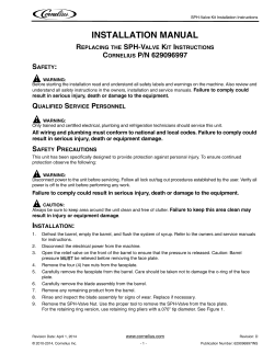
INSTALLATION
BLACK LED LAYDOWN CURVED LICENSE PLATE FRAME
THANK YOU FOR CHOOSING KϋRYAKYN!
PROTECT YOURSELF AND OTHERS FROM POSSIBLE INJURY AND PROPERTY
DAMAGE OR LOSS. PAY CLOSE ATTENTION TO ALL INSTRUCTIONS, WARNINGS,
CAUTIONS, AND NOTICES REGARDING THE INSTALLATION, USE, AND CARE OF
THIS PRODUCT.
THIS INDICATION ALERTS YOU TO THE FACT THAT
IGNORING THE CONTENTS DESCRIBED HEREIN CAN
RESULT IN POTENTIAL DEATH OR SERIOUS INJURY.
This indication alerts you to the fact that ignoring
the contents described herein can result in minor or
moderate potential injury.
This indication alerts you to the fact that ignoring the
contents described herein may negatively affect product
performance and functionality or damage the product itself
or the product to which it is being attached.
MAKE SURE THE FOLLOWING PARTS HAVE BEEN INCLUDED IN THE KIT:
1
1
1
Black L.E.D. Laydown Curved License Plate Frame Assembly
Hardware Kit Containing:
4
1/4”-20 X 9/16” Flat Socket Cap Screws
3
1/4”-20 X 1” Button Socket Cap Screws
6
1/4” Flat Washers
3
1/4”-20 Nylock Nuts
1
12” Adhesive Pad
6
4” Cable Ties
1
Dielectric Grease Pack
1
1” X 8” Foam Tape
2
Female T-Tap Connectors
2
Male Spades
Installation Instructions
YOU WILL ALSO NEED:
Set of Hex Wrenches, Set of Combination Wrenches, Drill and Drill Bits, Center Punch, Wire Crimping
Tool, Masking Tape
These installation instructions contain important information.
Ensure that the end user receives this copy and is aware of its
importance for future reference.
STEP 1
Read and understand all steps in the instructions before starting the installation;
park the motorcycle on a hard, level surface and turn IGN OFF;
allow the engine and exhaust system to cool;
Remove the seat; disconnect the NEGATIVE (-) battery cable.
NOTE:
Not all of the included hardware will be used for every installation.
Avoid damage to the motorcycle. Protect painted surfaces
with a soft cloth or blanket.
7678-21MC-1214
-cont.-
7678
CUSTOMER SERVICE
877.370.3604 (toll free)
INSTALLATION QUESTIONS
[email protected]
or call 715.247.2983
LIMITED WARRANTY
Küryakyn warrants that any Küryakyn products
sold hereunder, shall be free of defects in
materials and workmanship for a period of one
(1) year from the date of purchase by the
consumer excepting the following provisions:
● Küryakyn shall have no obligation in the event
the customer is unable to provide a receipt
showing the date the customer purchased the
product(s).
●The product must be properly installed,
maintained and operated under
normal conditions.
●Küryakyn makes no warranty, expressed or
implied, with respect to any gold plated
products.
●Küryakyn shall not be liable for any
consequential and incidental damages, including
labor and paint, resulting from failure of a
Küryakyn product, failure to deliver, delay in
delivery, delivery in nonconforming condition, or
for any breech of contract or duty between
Küryakyn and a customer.
●Küryakyn products are often intended for use in
specific applications. Küryakyn makes no
warranty if a Küryakyn product is used in
applications other than intended.
●Küryakyn electrical products are warranted for
one (1) year from the date of purchase by the
consumer. L.E.D.’S contained in components of
Küryakyn products will be warranted for defects
in materials and workmanship for 3 years from
the date of purchase where as all other
components shall be warranted for one(1) year.
This includes, but is not limited to; control
modules, wiring, chrome & other components.
●Küryakyn makes no warranty of any kind in
regard to other manufacturer¹s products
distributed by Küryakyn. Küryakyn will pass on
all warranties made by the manufacturer and
where possible, will expedite the claim on behalf
of the customer, but ultimately, responsibility for
disposition of the warranty claim lies
with the manufacturer.
ABOUT OUR CATALOG
For purchasing Küryakyn® products, you
can receive a complete catalog free of charge.
Send the Proof-of-Purchase below with your
address to: Küryakyn
454 County Road V V
Somerset, WI 54025-9031
Please indicate either Accessories Catalog for
Harley-Davidson® or GL & Metric Cruisers.
Be sure to ask your local dealer about other
Küryakyn® products, the motorcycle parts and
accessories designed for riders by riders.
©2005 Küryakyn USA® All Rights
reserved.
VICTORY CROSS COUNTRY AND CROSS ROAD INSTALLATION:
STEP 2
Refer to PIC 1. Remove the existing license plate mount from the bike. Set the mount
aside, it will not be reused. Save the hardware, it will be reused.
STEP 3
Refer to PIC 2. Apply a few strips of masking tape across the installation area to protect the paint on the rear fender. Using the existing hardware, install the Back Plate to
the fender;
leave the fasteners snug for now.
REMOVE STOCK
MOUNT
STEP 4
Center the Back Plate on the fender. Use a marker to mark a hole location as shown in
PIC 2.
STEP 5
Remove the Back Plate from the motorcycle. Using a center punch, mark the location of the hole to be drilled.
NOTE:
PIC 1
RETAIN THIS
HARDWARE
PIC 2
BACK
PLATE
Set a wooden 2X4 (or similar) between the fender and the tire
to prevent drilling into the tire.
MEASURE TWICE—DRILL ONCE. Double check all reference
marks made on the fender BEFORE drilling. Kuryakyn is not
responsible for incidental or consequential damages resulting from this installation.
HOLE
LOCATION
STEP 6
Using light pressure, carefully drill a 1/4” hole through the fender. De-burr the hole.
STEP 7
Remove the masking tape from the fender. Reinstall the Back Plate on the rear fender. (If you do
not want the Back Plate to rest against the paint, use the included 1” X 8” foam tape to cushion it
from the fender)
PIC 3
Center the Back Plate and tighten securely.
STEP 8
NOTE:
STEP 9
Mold your license plate to the same bend as the Frame.
You may need to modify your license plate to fit inside the frame. Cut a
notch to safely route the wiring through when installed.
Route the wire harness from the Frame light through the hole drilled in STEP
existing harness towards the seat area; secure with the included Cable Ties.
6; route along the
Secure the wiring away from moving parts, pinch points, or extreme heat.
Kuryakyn will not provide warranty coverage on any electrical component
that fails due to pinched, crimped, broken, abraded, melted, or frayed
wires.
STEP 10
Install the Frame over the license plate and Back Plate. Start all four screws in their threads before
final tightening.
STEP 11
Refer to PIC 3. In the under-seat area, open the black plastic wire covering of the taillight harness
(the sheathing will have a slit in it that can be peeled apart); locate the BLUE wire with PINK
tracer and one of the BLACK wires.
STEP 12
Crimp the supplied Female T-Taps on the BLUE/PINK and BLACK wires.
STEP 13
Locate the RED (Power) and BLACK (Ground) wires from Plate Frame.
Crimp one of the supplied Male Spades on the RED wire from the Frame light; connect it to the
Female T-Tap on the BLUE /PINK tracer wire.
Crimp a Male Spade on the BLACK wire from the Frame light; connect it to the Female T-Tap on
the BLACK wire.
-cont.-
BLACK LED LAYDOWN CURVED LICENSE PLATE FRAME
PAGE
2
INSTALLATION
STEP 14
Reconnect the NEGATIVE (-) battery cable, turn IGN ON, and verify that ALL lights are working
correctly.
STEP 15
Reinstall the seat.
PIC 4
VISIBILITY IS A MAJOR CONCERN FOR MOTORCYCLISTS. A LIGHT MALFUNCTION COULD RESULT IN
DEATH OR SERIOUS INJURY. ENSURE PROPER LIGHT
OPERATION BEFORE RIDING THE MOTORCYCLE.
TYPICAL LONG FENDER INSTALLATION
It is the end user’s responsibility to ensure that all of the
fasteners (including pre-assembled) are tightened before
operation of the motorcycle. Kuryakyn will not provide warranty coverage on products or components lost or damaged
due to improper installation or lack of maintenance. Periodic
inspection and maintenance are required on all fasteners.
PIC 5
UNIVERSAL INSTALLATION:
STEP 16
Remove the existing license plate; set the plate aside, it will be re-used.
STEP 17
Determine the mounting location and position of the new license plate mount on
the existing license plate mount.
STEP 18
Use any combination of the slots shown in PIC 4 to mount the license plate frame
to the motorcycle license plate mount. Use a minimum of two bolts to mount the plate Frame to
the motorcycle.
TYPICAL SHORT FENDER INSTALLATION
NOTE:
STEP 19
Use the included adhesive pad for
padding on custom applications.
Refer to FIG 1. Secure the Frame to the mounting
location with the included 1/4”-20 x 1” Button Socket
Cap Screws, 1/4” Flat Washers and 1/4”-20 Nylon
Insert Locknuts.
NYLOCK NUT
FIG 1
FLAT WASHER
EXISISTING PLATE
MOUNT
SLOTTED BACKING
PLATE
FLAT WASHER
STEP 20
Decide if you would like the LED Light on the top or
the bottom of the license plate and route the wire
harness accordingly.
NOTE:
HEX HEAD CAP
SCREW
You may need to modify your license plate to fit inside the frame. Cut a
notch to safely route the wiring through when installed.
STEP 21
Install the license plate frame over your plate.. Start all four screws in their threads before final
tightening.
STEP 22
Locate the Red and Black wire from the plate light. The Red wire is Power, the Black wire is
Ground.
STEP 23
On the bike, locate the wire harness that goes to the tail light on the bike. Turn IGN ON; using a
test light, determine a “keyed” power wire (one that has power with IGN ON and looses power
with IGN OFF) and a ground wire.
Turn IGN OFF. Mark each wire for reference.
STEP 24
Refer to
PAGE 2. Crimp a female T-Tap on each of the wires from STEP 23.
STEP 25
Route the wire harness from the plate light to the location that you are going to tap into the bike’s
wire harness. Use the included cable ties to secure the harness out of harms way.
PAGE
-cont.-
BLACK LED LAYDOWN CURVED LICENSE PLATE FRAME
3
INSTALLATION
STEP 26
Refer to FIG 2. Crimp one of the supplied Male Spades on the Red wire from the license plate
light; connect it to the female T-Tap on the power wire from
STEP 27
Refer to FIG 1 on PAGE 3. Crimp a Male Spade on
the Black wire from the plate light; connect it to the
female T-Tap on the ground wire from STEP 24.
STEP 28
Reconnect the NEGATIVE (-) battery cable.
STEP 24.
FIG 2
Turn IGN ON and check for proper functions on the tail
light and the new LED Plate Light.
Secure all the wires up and out of harms way with the
included cable ties.
VISIBILITY IS A MAJOR CONCERN FOR MOTORCYCLISTS. A LIGHT MALFUNCTION COULD RESULT IN
DEATH OR SERIOUS INJURY. ENSURE PROPER LIGHT
OPERATION BEFORE RIDING THE MOTORCYCLE.
It is the end user’s responsibility to ensure that all of the fasteners
(including pre-assembled) are tightened before operation of the motorcycle.
Kuryakyn will not provide warranty coverage on products or components
lost or damaged due to improper installation or lack of maintenance. Periodic inspection and maintenance are required on all fasteners.
PAGE
Ride On!
BLACK LED LAYDOWN CURVED LICENSE PLATE FRAME
4
INSTALLATION


© Copyright 2026