
CCR Liberty User Manual
Published by Liberty systems s.r.o., www.CCRLiberty.com Tomáš Sládek, Aleš Procháska, Jakub Šimánek Date of issue: 11. June 2015 CU HW rev. 1.4, HS HW rev. 3.0, FW 2.5 Introduction Use of this manual This user manual is part of the CCR Liberty documentation. The CCR Liberty is intended for use exclusively by a trained person who is capable of fully understanding the instructions contained in this manual or is in the process of training with the CCR Liberty in a course accredited by the manufacturer. The initial requirements of such a training course include qualification for diving with trimix recognized by a training agency and sufficient experience with technical diving. Responsibility of the CCR Liberty user Strong emphasis was placed on reliability during the development of the CCR Liberty. Individual internal parts are separated in order to minimize the impact that a failure of a given part may have on the rebreather’s basic functionality. A number of systems have multiple backups. The logic of the CCR Liberty’s control never disallows the start of a dive even in the event that malfunctions are detected; it only indicates the status if able to do so in light of the scope of damage. The extent of a malfunction according to which the user switches to a backup breathing apparatus, or starts a dive even with a partially malfunctioning rebreather, depends on the decision and responsibility of the user. The user must take into consideration the circumstances and degree of risk. When cave diving, the inability to submerge can mean the impossibility of returning from a dive; therefore the CCR Liberty does not impede submersion. A CCR Liberty user must accept the fact that diving involves risk. Adherence to everything that the user has learned in the CCR Liberty’s technical documentation and in training on diving with this rebreather can reduce the risk but cannot eliminate it. Safety when diving is further enhanced by regular training, methodical education and adherence to good diving practices. Diving with a rebreather requires a far higher degree of carefulness and discipline than diving with an open-circuit apparatus. If you do not accept the risk and you are not a trained, careful and disciplined diver, do not dive with the CCR Liberty. The manufacturer does not bear any responsibility for use of the CCR Liberty if the apparatus has been modified in any way that is not set forth in this manual or in the technical guidelines issued by the manufacturer. 3 System of documentation Version The technical documentation is subjected to a process of continual development and improvement. Therefore, please regularly check the website at www.CCRLiberty.com for updates. Use this manual only for hardware and software (firmware) version written on the title page. Technical guidelines The manufacturer can issue technical guidelines. It is strongly recommended that the user monitor the issuance of such guidelines at www.CCRLiberty.com and proceed according to the guidelines. Registered users will receive notifications on the issuance of guidelines by e-mail. Update of printed documentation The electronic form of the manual is always available in its complete, updated form. The electronic and printed forms of the manual may not be completely identical. In the case of changes of insignificant content (correction of minor typing errors, for example), only the electronic version is updated. User support Registered users are entitled to technical support. The scope of free support can be limited. The technical-support department at Liberty systems s.r.o. will endeavor to respond to technical questions from potential users and unregistered users. Prior to submitting a question, please familiarize yourself with the general principles of rebreather diving with trimix and the freely available CCR Liberty technical documentation. 4 Technical data Depth limits The maximum depth for which CCR Liberty meets requirements of the Harmonised Standard EN 14143:2013 is 100 m. Diluent Max. depth Air 40 m tmx 21/35 66 m tmx 18/45 78 m tmx (heliox) 10/90 > 78 m Additional limitation of depth depends on used diluent, see 3.1.5 Tank filling - Diluent. All components are tested in overpressure 6 MPa (depth 600 m). Depth gauge is checked in overpressure 3.5 MPa (depth 350 m). EC Type-examination was performed to 100 m simulated depth. Water temperature limits CCR Liberty is intended for use in water temperatures above 4 °C and less than 34 °C according to requirements of EN 14143:2013 (Article 5.1). The minimal temperature is set by CO₂ scrubber duration tests, which are done at 4 °C. CO₂ scrubber duration limit The maximum safe operating period of sorbent is 168 min, determined by a test pursuant to EN 14143:2013 (Article 6.6.2) during which 1.6 liters of CO₂ were added to the breathing loop per minute with ventilation of 40 liters per minute, in water with temperature 4 °C, exhaled gas with temperature 32±4 °C, 40 m depth an and limit at ppCO₂ 5 mBar. The sorbent’s actual maximum operating period can differ depending on the sorbent, temperature, depth and exertion of the diver. In normal conditions there can be considered scrubber duration from 4 h in deep cold water with moderate work to 6 hours for easy dive. For details see 3.1.1 Sorbent service life Weight The total weight of CCR Liberty ready for the dive, including fillings, is approx. 37 kg. For details see 1.15 Weights of individual parts 5 Contents Section 1: Technical design ................ 8 1.1 Basic schematic .................................10 1.2 Dive/surface valve ............................. 11 1.2.1 Inhalation valve........................................... 11 1.2.2 Exhalation valve.......................................... 11 1.2.3 Mouthpiece ................................................. 12 1.2.4 Usage with a full face mask ........................ 12 1.3 Hoses .......................................................... 13 1.3.2 Attachment to the head .............................. 13 1.3.3 Connection to the breathing bags ............... 14 1.3.4 Attachment of the DSV ............................... 14 Automatic diluent valve .............................. 15 1.4.2 Manual diluent bypass valve ....................... 15 Section 2: 2.1 Manual oxygen bypass valve ...................... 16 1.5.2 Overpressure valve ..................................... 16 Control elements ...............................32 Meanings of inputs in surface modes ......... 32 2.1.2 Meanings of inputs in dive modes .............. 33 2.1.3 Language .................................................... 33 Switching on the unit .........................34 2.2.1 2.3 Activation .................................................... 34 Surface mode ....................................35 2.3.1 Entering surface mode................................ 35 2.3.2 Surface mode primary screen..................... 35 2.3.3 Surface mode O₂ sensors screen ................ 36 2.3.4 Switching to other modes ........................... 36 2.3.5 ppO₂ control ................................................ 37 2.4 Oxygen tank ......................................17 Control-unit operation ..... 31 2.1.1 2.2 Exhalation bag ...................................16 1.5.1 1.6 1.15 Weights of individual parts ................30 Inhalation bag ....................................15 1.4.1 1.5 1.14 Ballast ................................................29 Corrugated hoses and accessories ....13 1.3.1 1.4 1.13 Buoyancy compensator .....................28 Dive mode .........................................38 2.4.1 Detailed screen ........................................... 38 2.4.2 Synoptic screen .......................................... 41 1.6.1 Tank ............................................................ 17 2.4.3 Big Screen................................................... 41 1.6.2 Valve ........................................................... 17 2.4.4 Dive profile screen ...................................... 41 1.6.3 Reduction valve .......................................... 17 1.6.4 Pressure reading ......................................... 17 1.7 2.5 Diluent tank .......................................18 CCR mode ..........................................42 2.5.1 Entering CCR mode..................................... 42 2.5.2 Switching to other modes ........................... 42 1.7.1 Tank ............................................................ 18 2.5.3 ppO₂ regulation ........................................... 42 1.7.2 Valve ........................................................... 18 2.5.4 Decompression ........................................... 43 1.7.3 Reduction valve and pressure reading........ 18 2.5.5 Specific handset control ............................. 43 1.7.4 Backup regulator (optional) ........................ 18 1.8 CO₂ scrubber ......................................19 1.9 Head ..................................................20 2.6 Manual CCR mode .............................44 2.6.1 Entering manual CCR mode ........................ 44 2.6.2 Switching to other modes ........................... 44 1.9.1 Control units................................................ 21 2.6.3 ppO₂ regulation ........................................... 44 1.9.2 Direct measurement of ppO₂ ...................... 21 2.6.4 Decompression ........................................... 44 1.9.3 Measurement of He content........................ 22 1.9.4 Pressure and depth measurement .............. 22 2.7.1 Entering bailout OC mode........................... 45 1.9.5 Temperature measurement ........................ 22 2.7.2 Switching to other modes ........................... 45 1.9.6 Solenoids..................................................... 22 2.7.3 Mixture........................................................ 45 1.9.7 Power supply ............................................... 23 2.7.4 Decompression ........................................... 45 1.10 Visual display units ............................ 24 2.7.5 Specific handset control ............................. 45 2.7 1.10.1 Handsets ..................................................... 24 2.8 Bailout OC mode ................................45 Setup .................................................46 1.10.2 Head-up display .......................................... 24 2.8.1 Setpoints..................................................... 46 1.10.3 Buddy display.............................................. 24 2.8.2 Mixtures ...................................................... 47 1.11 Backplate and mounting ....................26 2.8.3 Decompression ........................................... 48 1.12 Harness .............................................27 2.8.4 Alarms......................................................... 50 6 2.8.5 Preferences ................................................. 52 3.3.6 Water entry................................................. 74 2.8.6 Calibration................................................... 53 3.3.7 Submersion ................................................. 75 2.8.7 Faulty sensors ............................................. 54 3.3.8 In-water check ............................................ 75 2.8.8 Miscellaneous.............................................. 55 3.3.9 Descent....................................................... 75 2.9 3.3.10 Controlling buoyancy and trim.................... 76 Games ...............................................56 2.9.1 Sokoban ...................................................... 56 3.3.11 Mask clearing .............................................. 76 2.9.2 Snake .......................................................... 56 3.3.12 Increased physical exertion ........................ 77 Section 3: 3.1 3.3.13 Ascent ......................................................... 77 Procedures ...................... 57 3.4 Dive preparation ................................ 58 Post-dive procedures .........................78 3.4.1 Immediately after surfacing........................ 78 3.1.1 Replacement of CO₂ sorbent ....................... 58 3.4.2 Cleaning and disinfection ........................... 78 3.1.2 Assembling the rebreather body ................. 61 3.4.3 CO₂ scrubber maintenance ......................... 80 3.1.3 Mounting the rebreather body .................... 62 3.4.4 Battery care ................................................ 80 3.1.4 Attaching the counterlungs and hoses ........ 62 3.4.5 Dive log download ...................................... 80 3.1.5 Tank filling .................................................. 63 3.4.6 Long-term storage ...................................... 81 3.1.6 Battery charging ......................................... 66 3.1.7 Calibration of the oxygen sensors ............... 66 3.1.8 Preparing the bailout apparatus ................. 67 3.1.9 Setting parameters ..................................... 67 3.5 3.1.10 Directional valve check ............................... 68 3.1.11 Physical inspection ...................................... 68 3.2 Pre-dive inspection ............................ 69 Emergency procedures ......................82 3.5.1 Emergency ascent (bailout) ........................ 82 3.5.2 Oxygen-source malfunction ........................ 82 3.5.3 Diluent-source malfunction ......................... 83 3.5.4 Scrubber malfunction ................................. 84 3.5.5 Inadvertent release of the mouthpiece....... 85 3.5.6 Flooding ...................................................... 86 3.2.1 Internal testing of the control units ............. 69 3.5.7 Loss of buoyancy ........................................ 86 3.2.2 Negative pressure test ................................ 69 3.5.8 Rescue on the surface ................................ 87 3.2.3 Positive pressure test .................................. 70 3.5.9 Malfunction of oxygen-concentration 3.2.4 Solenoid testing .......................................... 70 3.2.5 Battery testing ............................................ 70 3.2.6 Helium-sensor test ...................................... 70 3.2.7 Comparison of pressure sensors ................. 71 3.2.8 Comparison of oxygen sensors and measuring ................................................... 87 3.6 calibration thereof....................................... 71 3.2.9 HUD inspection ........................................... 71 3.2.10 BD inspection .............................................. 71 3.3 3.3.1 Breathing high oxygen content gases......... 72 3.3.2 Putting on the apparatus ............................ 73 3.3.3 Using the DSV ............................................. 73 3.3.4 Monitoring of devices .................................. 74 3.3.5 Switching to CCR mode ............................... 74 3.6.1 Tools and replacement parts ...................... 88 3.6.2 Detection of leaks ....................................... 88 3.6.3 Regular service inspection .......................... 89 3.6.4 Long-term maintenance ............................. 89 3.6.5 Firmware update......................................... 89 3.7 Diving ................................................72 7 Maintenance ......................................88 Transport ...........................................93 3.7.1 By car.......................................................... 93 3.7.2 By boat ....................................................... 93 3.7.3 By plane ...................................................... 93 Section 1: Technical design 8 9 1.1 Basic schematic The principle of the rebreather consists in recycling the breathing mixture. Carbon dioxide is removed from the exhaled mixture and is again prepared for the next inhalation after replenishment with oxygen. The composition of the breathing mixture changes continuously. 10 1.2 Dive/surface valve The breathing mixture is delivered to the dive/surface valve (DSV) by the corrugated hose from the left. When inhaling, the mixture passes through the inhalation valve to the mouthpiece and then into the diver’s respiratory tract. When exhaling, it passes through the exhalation valve into the corrugated hose on the right. The direction of the mixture’s flow is indicated on the DSV. 1.2.1 Inhalation valve The inhalation valve ensures that the exhaled mixture cannot return to the inhalation bag and is not repeatedly inhaled by the diver without removal of carbon dioxide and replenishment with oxygen. The inhalation valve is situated in the connection of the left corrugated hose. A similar mushroom valve can be found in, for example, the exhalation valve of the second stage of the regulator of an open-circuit apparatus. This is one of the most critical parts of the rebreather. It is difficult to detect a malfunction in this part during a dive, and such a malfunction can lead to loss of consciousness. 1.2.2 Exhalation valve The exhalation valve directs the exhaled mixture via a corrugated hose to the exhalation bag. It ensures that the diver does not re-inhale the exhaled mixture. The exhalation valve is situated in the connection of the right corrugated hose. Closing the dive/surface valve If the diver is in the water and is not breathing from the DSV, the DSV must be closed. Otherwise, the circuit will be flooded with water. 11 Closing the DSV is done using the gate handle in the front part of the DSV. In the open position, the handle protrudes forward; in the closed position, it is tilted downward. 1.2.3 Mouthpiece Tight sealing of the mouthpiece in the diver’s mouth prevents entry of water into the circuit. The DSV and corrugated hoses function with greater force than the regulator of an open-circuit apparatus. Therefore, the anatomically suitable shape of the rebreather’s mouthpiece and proper clenching in the mount are far more important. We do not recommend using a mouthpiece that can be shaped according to the diver’s bite after heating. The resulting restriction of movement of the lower jaw leads to unilateral stress and rapid onset of fatigue of the mastication muscles. 1.2.4 Usage with a full face mask Even though the mechanical dimensions would allow connection of a full face mask, in a full face mask it is not possible to replace the mixture inlet from an open circuit with the inlet from a rebreather. One of the reasons for this is the necessity of defogging the visor. Consult with the manufacturer regarding possibilities of connecting the rebreather to a full face mask. Use of such an apparatus will require procedures that deviate from this manual and from standard procedures taught in a course accredited by the rebreather’s manufacturer. 12 1.3 Corrugated hoses and accessories 1.3.1 Hoses Corrugated hoses made of EPDM rubber. Compatible chemical agents must be used for cleaning and disinfection of the hoses (see Chapter 3.4.2 Cleaning and disinfection). The corrugated hoses can be damaged if subjected to excessive stress. In particular, it is necessary to guard against perforation, cutting and excessive wear. Long-term deformation of the hose, for example when storing and preparing the unit, is also undesirable. Using the hoses for grasping or fastening the CCR Liberty in or out of the water is not permissible. The corrugated hoses are part of the mechanically least durable part of the CCR Liberty. Focus the appropriate level of attention on protecting them. 1.3.2 Attachment to the head Different bayonet connectors on the elbows for connecting the corrugated hoses to the head preclude interchangeability. Unlike all other bayonet connectors on the CCR Liberty, the bayonet connector on the exhalation side has three protrusions. 13 Elbow on the inhalation side (left) and exhalation side (right). 1.3.3 Connection to the breathing bags The T-pieces have standard bayonet connections. On the exhalation side, the T-piece has a partition that directs any water that may penetrate the DSV to the exhalation bag and improves blending of the mixture with oxygen added using the manual bypass valve. 1.3.4 Attachment of the DSV Attachment to the corrugated hoses is done with axial teeth, which mesh together and are secured with a wire retaining ring. The baskets of the mushroom valves are inserted into the connector. When handling the basket, pay increased attention to their correct orientation. 14 1.4 Inhalation bag The inhalation bag is mounted on the left part of the harness (from the diver’s perspective when wearing the CCR Liberty). It is comprised of an external cover of resilient textile, which defines the shape and ensures mechanical protection, and an internal bag of polyurethane sheet. It is connected to the breathing circuit with a T-piece via the upper bulkhead with a bayonet connector. The inhalation bag is affixed to the harness with two stainless-steel clasps and Velcro flaps. It can be easily removed for cleaning, disinfection and other handling. See also 3.4.2 Cleaning and disinfection. 1.4.1 Automatic diluent valve The automatic diluent valve (ADV) is mounted in the middle bulkhead with a bayonet connector. In the event of a decrease of volume of the inhalation bag, the control lever of the ADV is pressed by the opposite wall of the bag and the ADV automatically adds diluent to the breathing circuit. At the ADV inlet, there is a valve that shuts off the intake of diluent from the connected medium-pressure hose. It is operated by sliding the collar. It is used in the event of a malfunction during which the ADV would add an excessive amount of diluent, for example as the result of freezing and free-flow. 1.4.2 Manual diluent bypass valve The manual diluent bypass valve is situated in the lower bulkhead of the inhalation bag and is equipped with a bayonet connector. It is attached to the medium-pressure hose with a seatec-style quick-release connector. It is operated by pressing the center button. Safety lock prevents accidental falling out of diluent valve. Follow these steps to remove. 15 1.5 Exhalation bag The exhalation bag is situated on the right part of the harness (from the diver’s perspective when wearing the CCR Liberty). The design and means of connection to the harness and breathing loop are analogous to that of the inhalation bag. See also 3.4.2 Cleaning and disinfection. 1.5.1 Manual oxygen bypass valve The manual oxygen bypass valve is situated in the middle bulkhead of the exhalation bag and is equipped with a bayonet connector. It is attached to the medium-pressure hose with an oxygen quick-release connector. This connector is similar to standard seatec-style quick-release, but with shorter collar. A standard seatec-style quick-release connector can not be connected to oxygen quick-release connector. Bayonet connector on the oxygen bypass valve has three protrusions, the same bayonet as the elbow on the exhalation side. Use oxygen-compatible lubricant for maintenance of the oxygen bypass valve. The rest is identical to the manual diluent bypass valve. 1.5.2 Overpressure valve The overpressure valve is mounted in the lower bulkhead of the exhalation bag and is equipped with a bayonet connector. The required overpressure is regulated by rotation. When set to minimal overpressure (by turning counterclockwise), the valve is opened; only a mushroom valve ensures minimal overpressure. The valve is closed completely by turning it fully in the opposite direction. Safety lock prevents accidental falling out of overpressure valve. Removing is similar to removing of Manual diluent bypass valve. 16 1.6 Oxygen tank 1.6.1 Tank Three-liter steel tank, 100 mm diameter 200 bar filling pressure. The original 300 bar filling pressure of the bare tank was changed with respect to the provisions of the valid technical standards. The tank is labeled OXYGEN. The tank is situated on the right from the diver’s perspective when wearing the CCR Liberty. For more information on filling, see 3.1.4 Oxygen. 1.6.2 Valve The valve has a M26×2 outlet connection in the 200 bar variant. 1.6.3 Reduction valve The CCR Liberty uses Apeks DST4 first-stage regulator with a specially made revolving medium-pressure component, which is mounted on the backplate. This serves as the lower tank-mounting point; in the middle part, the tank is attached with a strap and Velcro. The reduction valve is equipped with a intermediate-pressure safety overpressure valve. 1.6.4 Pressure reading The oxygen pressure gauge is situated on the right side; the HP hose runs through an opening in the backplate. 17 1.7 Diluent tank 1.7.1 Tank Three-liter steel tank, 100 mm diameter, 230 bar filling pressure. The original 300 bar filling pressure of the bare tank was changed because a 230 bar valve is used. The tank is labeled DILUENT. The tank is situated on the LEFT from the diver’s perspective when wearing the CCR Liberty. For more information on filling, see 3.1.4 Diluent. 1.7.2 Valve The valve has a G 5/8”outlet connection in the 230 bar variant. 1.7.3 Reduction valve and pressure reading The design solution is similar to that of the oxygen tank, only reversed. 1.7.4 Backup regulator (optional) The second stage of regulator may be connected to the output of the first stage of the diluent through interstage hose of appropriate length (according to the personal preferences). This regulator can be used as a backup if the diluent at a given depth is breathable (oxygen partial pressure between 0.16 and 1.6 bar). The backup regulator connected to the diluent may be useful for sanity breaths and for prolonged switching to a backup apparatus. The manufacturer considers that the negatives associated with the backup regulator location on the diver's outfit dominate. Due to the small volume of diluent cylinder it is usable only for short periods (in a greater depth of only a few breaths). The greatest risk we consider a false sense of security that could result in not using a separate backup breathing apparatus by less disciplined users. 18 1.8 CO₂ scrubber The CCR Liberty uses a radial scrubber. The breathing mixture flows from the outside to the center of the scrubber cartridge. The scrubber consists of a scrubber cartridge inserted into a scrubber canister, which comprises the external body (tube) of the CCR Liberty. A water trap is situated in the lower part of the canister. The walls of the cartridges consist of external and internal metal mesh. The bottom of the cartridge has openings on the periphery that enable condensation to flow from the canister walls to the water trap. A lid presses down on the scrubber cartridge by means of springs attached to the pressure plate. The pressure plate is fastened to the central tube with a retaining ring. The scrubber cartridge capacity is approximately 2.5 kg of sorbent. The sorbent volume is approximately 2.82-2.99 l. The service life and replacement of the sorbent are described in Chapter 3.1.1 Replacement of CO2 sorbent. 19 1.9 Head The head is mounted on the CO₂ scrubber canister. When mounting the head, push the scrubber-canister pin into the opening on the head and close the head. The head contains the control units; solenoids; oxygen, helium and pressure sensors; and batteries. If it is difficult to remove the head, place the rebreather on a hard, level mat as shown in the illustration. Press down on the head and the scrubber canister with your hands. 20 1.9.1 Control units The control units (CUs) are independent. A display unit (handset – HS) is connected to each CU, which has its own power source, solenoid, temperature gauge and pressure, O₂ partial pressure and He concentration sensors. In the event of a failure of one control unit, the other control unit takes over automatically. Communication of the control units with each other and with the handsets is conducted via a bus. The handset is powered from the source of the relevant control. The handsets are necessary only for control of the rebreather by the user and for displaying the results of the control units’ activities. In the event of a malfunction of both handsets, both CUs (or the remaining functional CU) will continue to regulate ppO₂ without change according to the last adjusted setpoint. In the event of breakdown of communication between the units, each unit controls one solenoid. The control algorithm is sufficiently robust to ensure that deviation of ppO₂ from the allowed limits will not occur during dual, parallel running of regulation. Connection to a computer The memory of operating protocols and content of the memory card can be read via a USB adapter connected to the handset connector as with a standard USB mass storage device (similarly as with a standard flash disk). During the time of USB connection, the control unit is powered from the USB port and, at the same time, the battery is charged (reduced current, only if it is connected). Each control unit is connected separately. 1.9.2 Direct measurement of ppO₂ Common R22D-type electrochemical ppO₂ sensors are used for measuring. Two sensors are connected to each CU. All sensors are located on the inhalation side. The diver can manually exclude a sensor from operation and manually return an excluded sensor to operation. The manual option is superordinate to automatic detection of faulty sensors. If all sensors are excluded, the CCR Liberty automatically switches to the backup algorithm for calculation of the partial pressure of oxygen by indirect means using measurement of the He content. Circulation of the mixture in the breathing loop is necessary for the accuracy of measuring. If the user does not breathe from the rebreather, the mixture in the vicinity of the oxygen sensors can have a different proportion of oxygen than that of the mixture in different parts of the breathing loop and the displayed data can thus be inaccurate. A discrepancy can similarly occur in the event of rapid descent, when a larger amount of diluent is added. Therefore, the diluent must be breathable. See 3.1.4 Diluent. 21 1.9.3 Measurement of He content The helium concentration is determined by the velocity of sound in the mixture. The He concentration sensors are connected to the inhalation side. Exchange of the mixture in the internal space of the sensor occurs as the result of a pressure drop caused by circulation of the mixture in the breathing loop. If the user does not breathe from the rebreather, such exchange will not occur and the measured (and displayed) data may be inaccurate. If the utilized diluent contains He and its composition was measured prior to the dive, the He-concentration measuring function can be used for reverse determination of the concentration of oxygen in the mixture based on the fact that the ratio of inert gases remains constant (process according to patent no. 303577). This principle of measuring the oxygen concentration (and its subsequent automatic conversion on the basis of the known ambient pressure to partial pressure) is used as the backup method of measuring ppO₂ in the event of malfunction of all electrochemical ppO₂ sensors. This method is intended for use only in emergency situations. If possible, use the apparatus for bailout. Do not disassemble the sensors; disassembly can result in irreparable damage. 1.9.4 Pressure and depth measurement Each of the CCR Liberty’s control units uses dual pressure sensors. The first sensor, intended for measuring low pressures, is used for determining sea level, for calibration of the ppO₂ sensors, and for improving the accuracy of depth data in the zone closely below the surface. The second sensor is intended mainly for measuring hydrostatic pressure. The maximum scope of the sensor corresponds to the depth of 300 m. 1.9.5 Temperature measurement The temperature in the breathing circuit is measured by temperature sensors within the pressure sensors. The water-temperature sensors are situated in the handsets. Temperature data serve primarily for correction of the measuring of other quantities. The water temperature shown on the HS display is only approximate. 1.9.6 Solenoids The control units communicate with each other and, in normal circumstances, open the solenoid valves, which supply oxygen to the breathing circuit. 22 1.9.7 Power supply The minimum service life of the batteries is six months. The typical service life of the batteries is two years. See also 3.1.6 Battery charging. 23 1.10 Visual display units 1.10.1 Handsets The handsets provide the CCR Liberty’s user with comprehensive information on the rebreather’s status and the course of the dive. All functions of the control units are controlled using the handsets. The handsets are fully equivalent functionally. In the event of a malfunction of one handset, the diver simply uses the other handset. In the course of a dive, it is possible to set a different display mode on each handset. For more information on handset operation, see Section 2: Control-unit operation. 1.10.2 Head-up display The head-up display (HUD) shows the current partial pressure or CCR error status during the dive. Other statuses are displayed in standby mode, during charging and when the unit is connected to a computer. If you are not entirely sure what the HUD is displaying, check the parameters on the handset display. Always check it if the HUD displays a warning (outer LED blinks red) or an alarm (all three LEDs flashes red four times). See the table below for the various HUD signals. 1.10.3 Buddy display The buddy display shows whether the values of the partial pressure of oxygen are in the range that is suitable for breathing or if an error situation has occurred. The displayed information is intended for the diving partner of the CCR Liberty’s user. Prior to diving, the user of the CCR Liberty must familiarize his/her diving partner with the buddy display’s functionality and agree on the emergency procedure to be carried out in the event that the buddy display indicates an error situation. See the following table for the various buddy-display signals. 24 HUD and buddy-display signals HUD signals Mode Event / state Startup Initializing components Binary coded service numbers Dive mode (standard) Standby (switched off from menu) Mass storage mode (USB adaptor connected) LED 1 ppO₂ < 0.16 ● red blinking 0.16 ≤ ppO₂ < 0.20 ● red blinking LED 3 BD signals ● red blinking ● red blinking ● red blinking ● red 0.20 ≤ ppO₂ < 0.25 ● 8× blue flash ● green 0.25 ≤ ppO₂ < 0.35 ● 7× blue flash ● green 0.35 ≤ ppO₂ < 0.45 ● 6× blue flash ● green 0.45 ≤ ppO₂ < 0.55 ● 5× blue flash ● green 0.55 ≤ ppO₂ < 0.65 ● 4× blue flash ● green 0.65 ≤ ppO₂ < 0.75 ● 3× blue flash ● green 0.75 ≤ ppO₂ < 0.85 ● 2× blue flash ● green 0.85 ≤ ppO₂ < 0.95 ● 1× blue flash ● green 0.95 ≤ ppO₂ ≤ 1.05 ● green ● green 1.05 < ppO₂ ≤ 1.15 ● 1× green flash ● green 1.15 < ppO₂ ≤ 1.25 ● 2× green flash ● green 1.25 < ppO₂ ≤ 1.35 ● 3× green flash ● green 1.35 < ppO₂ ≤ 1.45 ● 4× green flash ● green 1.45 < ppO₂ ≤ 1.55 ● 5× green flash ● green 1.55 < ppO₂ ≤ 1.65 ● 6× green flash ● green 1.65 < ppO₂ ≤ 2.0 ● red blinking ● red blinking ● red ppO₂ > 2.0 ● red blinking ● red blinking ● red blinking Alarm ● 4× red flash ● 4× red flash no change ● 4× red flash Standby ● slowly flashing Charging ● 1. red Charger connected but no power supply ● red blinking ● 2. red ● 3. red Fully charged ● green ● green ● green ● green Charging failed ● red blinking ● red blinking ● red blinking ● red blinking Reading ● green ● orange ● green Writing ● red ● orange ● red intensive No action Download firmware LED 2 Connected ● slowly flashing ● red ● red blinking ● orange ● purple Downloading ● purple blinking ● purple ● purple ● purple Color blind mode If you can not distinguish blue and green LED light, check “Color blind mode” in menu Setup – Preferences – Indication. Signals for 1.05 ≤ ppO₂ ≤ 1.65 will be changed according the following table: Dive mode (color blind) 1.05 < ppO₂ ≤ 1.15 ● 1× green flash ● 1× green flash 1.15 < ppO₂ ≤ 1.25 ● 2× green flash ● 2× green flash 1.25 < ppO₂ ≤ 1.35 ● 3× green flash ● 3× green flash 1.35 < ppO₂ ≤ 1.45 ● 4× green flash ● 4× green flash 1.45 < ppO₂ ≤ 1.55 ● 5× green flash ● 5× green flash 1.55 < ppO₂ ≤ 1.65 ● 6× green flash ● 6× green flash 25 1.11 Backplate and mounting The method of mounting the CCR Liberty on the diver’s body is based on the backplate and harness common among wing-type buoyancy compensators used in technical diving. The body of the rebreather, comprised of the scrubber canister and attached head, is attached to the backplate with a cam. The cam lever cannot be released when the diver is wearing the rebreather. The CCR Liberty’s integrated stand, which serves as a lumbar support, is intended for setting the rebreather on a hard, level surface with sufficient rigidity. Always secure the standing rebreather against falling. If needed, it is possible to remove the CCR Liberty’s backplate, together with the buoyancy compensator, from the components specific for the rebreather and use it with the harness for opencircuit diving. It enables attachment of a twin-set (two tanks firmly connected with stainless steel bands) using bolts and wing nuts as is common in technical diving, as well as attachment of a single tank with a strap with fastener (not included with the CCR Liberty). With the slot in the lower part, the rebreather’s body fits into the protrusions of the stand. 26 1.12 Harness The backplate is supplied with harness that is threaded through in a way that ensures proper system functioning. Do not change the way the harness is fed through the backplate. If you do try to take the harness out, record or remember exactly how it is threaded through in order to prevent interference with the functioning of the whole system. It is necessary to adjust the harness so that it fits properly. Adjust the harness without the mounted scrubber canister, head, corrugated hoses and breathing bags. Adjust the length of the shoulder straps so that it is possible to insert three fingers (index, middle and ring) under the straps at the collar-bone level without great resistance but not entirely freely. The chest D-rings should be as low as possible, while still allowing you to cross your arms over your chest comfortably. The D-rings should be high enough for you to reach the left ring with your left thumb, and the right ring with your right thumb. The D-ring on the left side of the waist strap should be roughly on your hip. Adjust the length of the left part of the belt strap so that it passes through the eye of the crotch strap and there is a distance of approximately 5 cm (strap width) between the ring and the eye. Adjust the right part so that the strap is slightly tight. If you shorten a strap, leave sufficient reserve for the various thicknesses of different suits and possible change of body dimensions. After shortening, it is necessary to deburr the ends of the straps by heat sealing them with a cigarette lighter or candle. Do this carefully and proportionately so that a hard surface is not formed on the strap ends. Adjust the length of the crotch strap so that it passes closely to the body but does not bind. Set the position of the rear D-ring as low as possible but sufficiently high so that it does not place pressure on the buttocks when swimming. The rear D-ring should be within the diver’s reach. Test the exact position of the rear D-ring in the water with the complete apparatus. Do not shorten the straps after the first fitting. Wait until you test your gear in the water. You will be doing additional adjustments for 3 to 5 dives until the gear is fitted properly. 27 1.13 Buoyancy compensator Wing-type buoyancy compensator (BCD) with displacement of 200 N. The compensator’s design and materials correspond to the demands placed on equipment used in cave diving. The wing has a two-ply design. The internal bladder is made of high-frequency-welded Cordura 560 fabric with PU coating. The wing’s external cover is made of Cordura 2000 fabric. The wing is attached with screws along the periphery of the backplate. In order to achieve the correct position of the inflator, pass the medium-pressure hose through the rubber ring on the corrugated hose, then through the rubber ring on the shoulder strap and finally through the second rubber ring on the corrugated hose. Do not skip either of the rings on the corrugated hose; upon disconnecting the quick-release connector from the inflator, it could recede so far that it would be difficult to find it. The buoyancy compensator is not a life preserver. It does not maintain the diver in a face-up position. It is not designed to hold the diver’s face above the surface should he/she become unconscious or immobile. Marking on backplate indicates that BCD is suitable for use with two 3 litre cylinders & rebreather. Of course, any number of neutrally buoyant bailout cylinders can be added to provide enough bail out gas supply. It can be applied to any other piece of equipment with neutral buoyancy, such as propulsion vehicles (scooters), large diving lights etc. There are some options if bailout cylinders are not neutrally buoyant perfectly and you need large quantity of backup gas. First option, typical for cave diving, is not to carry all the gas in one moment. Put stage tanks with backup gas to the appropriate points on the cave line during a preparation dive. Then make a push dive(s). Then collect unused backup gas on a cleanup dive. Second option, typical for deep wreck diving, is making your backup tanks buoyancy perfectly neutral. You can achieve this by light regulator, SPG and hoses attached to stage tank (typically Aluminum S80) filled with helium rich gas mix. 28 1.14 Ballast The ballast system is composed of two pouches placed on the sides of the scrubber canister and attached to the tanks. In the lower part of the pouches, there is an eyelet through which the attachment strap of the rebreather body is passed. The eyelet in the upper part is generally not utilized; it is intended for additional securing if needed. The internal pouches, which contain the individual weights, are inserted into the external pouches. The upper flap of the external pouch is intended for ordinary insertion and removal of weights, For emergency jettisoning of ballast, pull the red strap in the lower part of the pouch, by means of which the external pouch is opened and the internal pouch containing the ballast is released. For ordinary removal of the ballast, do not use the method for emergency jettisoning. This could lead to fouling and excessive wear of the Velcro, which in the extreme case could in turn lead to diminished reliability of the ballast system. A diver in a dry suit typically needs 2x4 kg of ballast. Determination of the optimum size and distribution of ballast is a subject of the course on diving with the CCR Liberty. 29 1.15 Weights of individual parts Those weights are indicative only, were mostly determined by weighing. In particular apparatus may vary. Backplate with the wing, harness and hoses, without counterlungs 10.68 kg Weight pockets (without weights) 0.43 kg Couterlungs incl. all valves 1.86 kg Tank with valve, empty 5.44 kg Corrugatet hose, complete 1.11 kg Scrubber body and cartridge, without sorbent 3.76 kg Head incl. handsets, HUD and BD 4.59 kg Charger with cable 0.09 kg Supplied accessories and small parts (without chargers) 1.00 kg Peli Stormcase iM2975 10.30 kg Oxygen 3 l 200 bar 0.84 kg Diluent (air) 3 l 300 bar 0.91 kg Sofnolime 2.50 kg Energy stored in batteries 4.16×10 30 -11 kg Section 2: Control-unit operation 31 2.1 Control elements All operating control is concentrated in the handsets. The following inputs and combinations thereof are differentiated: Press upper key Press lower key Press both keys Long press upper key Long press lower key Long press both keys Coded key press (press both keys, then release one key and press it again, then release both keys) Tilt the HS away from yourself Tilt the HS toward yourself Tilt the HS to the left Tilt the HS to the right Tap the display glass Shine a light on the display “Long press” means pressing the key for more than 2.5 seconds. The key-press operation is terminated at the moment the key is released or, in the case of pressing both keys, when the last key is released. The upper/lower keys and directions of tilting are determined by the configuration of the given HS, depending on whether it is set up for the left or right hand. HS tilting can be changed in the configuration to tapping on the HS from any of the four sides. 2.1.1 Meanings of inputs in surface modes The keys and other inputs are assigned meanings in connection with the current navigation item in the menu. At the same time, however, general rules, which apply wherever possible, are determined for their use. Press upper key — confirmation of the menu item just selected Press lower key — cycle downward through the menu Press both keys — exit the menu without performing any action Long press upper key — page up Long press lower key — page down Long press both keys — return to main screen 32 Coded key press — switch to maintenance mode (this can be done only from the main screen) Tilt HS away from yourself — increase of the entered digit by one or check flag Tilt HS toward yourself — decrease of the entered digit by one or uncheck flag Tilt HS to the left — move the cursor to the left Tilt HS to the right — move the cursor to the right Wherever possible (menu, editing screen), helpful symbols relating to the keys are displayed. A symbol can be either next to a key, indicating the action executed during a short key press, or between the keys, indicating the action executed during a short press of both keys. The symbol next to a key means scroll down one row in the menu. Scrolling in the menu is cyclical, so the first row appears again after the last row. The scroll-up function is not available due to two-key control. The symbol means return one level without executing any action. The symbol represents confirmation of the action or selection. 2.1.2 Meanings of inputs in dive modes The meanings of inputs are the same as in surface modes. Other possibilities are: Long press upper key — high setpoint Long press lower key — low setpoint Tilting is expanded with movement in decompression games; otherwise, entry of digits, for which tilting is used in surface modes, is limited during the dive to only special cases. Tapping on the display glass – switch on (activate) the display if it is switched off (deactivated). Shining a light on the display – in the dark, illuminating the display with a dive light activates it similarly as when tapping on the glass. In the light, the display can be activated by covering and then uncovering it. 2.1.3 Language All textual information on the CCR Liberty is in English. Controlling the apparatus requires knowledge of the English language minimally at a level that allows the user to thoroughly understand this information. 33 2.2 Switching on the unit In order for it to be possible to switch on the CCR Liberty’s control unit, it must be in standby mode, which is indicated on the HUD (slowly flashing blue LED) and the buddy display (slowly flashing green LED). If jumpers are removed (or turned so that the pins are not inserted in the connector), the rebreather’s control unit cannot be turned on with USB power when it is connected to a computer via an adapter. 2.2.1 Activation The device is activated by pressing both keys on either handset for three seconds. Automatic activation occurs in the event of entering the water with a deactivated rebreather. In such a case, the user cannot continue in the dive, but must perform complete pre-dive preparation on the surface as soon as possible. Using automatic activation, it is possible to switch on the CCR Liberty also in the event of damage or loss of both handsets. Use of this option is risky and should thus be considered only in the case of a rescue attempt, for example in the evacuation of a diver from the siphon of a flooded cave. Upon activation, the rebreather switches to surface mode. If submersion to a depth greater than 1.5 m occurs, the rebreather switches to CCR mode. 34 2.3 Surface mode 2.3.1 Entering surface mode The CCR Liberty switches to surface mode upon being switched on and activated by pressing the keys. In the water, surface mode can be selected in the menu if the depth is less than 1.5 m. 2.3.2 Surface mode primary screen Date and Time Maintain correct local time setting. It will be used for log recording. Stack time The scrubber stack timer runs all the time in dive mode (except OC bailout) regardless of depth, even on the surface. If you spend a long time in dive mode while not breathing from the rebreather’s loop, then increase the time for the stack time warning. Don't forget to reset the timer when you refill the scrubber (Predive → Stack time reset). Max altitude The maximum allowed altitude calculation is based on the ZHL decompression algorithm with an additional safety margin (GF = 0.80). No fly The calculation of the no fly time is based on the maximum allowed altitude according to the Bühlmann decompression algorithm ZHL. The air pressure in the cabin of a commercial aircraft is maintained at a level corresponding to air pressure at 1800–2400 m (6000–8000 feet) above sea level while cruising altitude falls in the range 11 000–12 200 m (36 000–40 000 feet). The no fly time calculation uses the decisive altitude 4464 m (14 646 ft). At this altitude compartments containing the oxygen masks will be opened automatically and the oxygen masks will drop down in front of the aircraft passengers. 35 Battery symbol A graphical indication of remaining battery capacity. Two batteries are indicated separately. The battery is full Bar height is proportional to remaining battery capacity Color is changed if less than half capacity Plugged to a charger Setpoints Descent (“-.—“ if disabled), low and high setpoint are listed. ppO₂ Actual partial pressure of oxygen as measured. 2.3.3 Surface mode O₂ sensors screen Not only the ppO₂ but also the voltage on sensors can be read. If the state of a sensor is not in operational mode (not connected, offline, error, excluded, disabled, uncalibrated), the appropriate tag appears instead of the ppO₂ value. You can find also the day time, the max. sensors reading difference and the stack time on the O₂ sensors screen. 2.3.4 Switching to other modes In the menu, the user can switch from surface mode to the CCR, manual CCR, bailout and standby modes. If submersion to a depth greater than 1.5 m occurs, the rebreather automatically switches to CCR mode. 36 2.3.5 ppO₂ control Simple ppO₂ control is started in surface mode. If the oxygen content in the loop falls below 19% (with respect to the current atmospheric pressure), ppO₂ is increased to 23% by opening the solenoid. Then O₂ is injected in six-second intervals. This control algorithm is intended to prevent dangerous decline of ppO₂ and subsequent loss of consciousness by the user, who could mistakenly breathe from the circuit without activating dive mode. PpO₂ control is subject to other conditions — the oxygen tank must be full, connected and open; ppO₂ sensors must be installed and calibrated; and the user may not exert excessive effort associated with high consumption of oxygen. PpO₂ control in surface mode maintains the oxygen level only closely above the hypoxia threshold; therefore, it may not be used routine for breathing. 37 2.4 Dive mode 2.4.1 Detailed screen The primary screen displays all necessary information during a dive. Most information is provided by clear values and unambiguous symbols. Dive time The timer starts after submersion (depth > 1.5 m) and halts after surfacing (depth < 0.5 m). In case of stay on the surface (or at very shallow depth) followed by a second submersion (during a time set in the dive termination timeout) the dive time indicated will be the time from the first submersion including the surface time. Depth The depth can be read in the units set in the setup (m or ft). Depth is calculated from measured hydrostatic pressure. Fresh water (default) or seawater density can be set for the depth calculation (units and salinity is set in Setup → Preferences). Setting of fresh/sea water doesn't affect decompression calculations. Decompression is based on ambient pressure and is independent of displayed depth. No deco You can stay for the indicated time at the current depth, breathing the current mixture (current He content and current SP), to avoid a decompression obligation. Ceiling The depth of the decompression ceiling decreases continuously up to the surface. The reading is not artificially stopped anywhere during the ascent. Always stay below the depth of the ceiling, even if the ceiling depth is very shallow. Ascent above the ceiling generates a warning. Further violation, more than 1 m (3 ft), leads to an additional alarm. Both alarms are logged. The decompression calculation will continue without a penalization. It is up to diver’s decision and responsibility, how to minimize probability of severe consequences. Battery symbols The battery is full Bar height is proportional to remaining battery capacity Color is changed if less than half capacity 38 Combined graphic symbol The combined graphic symbol on the detailed screen is intended for rapid orientation. It tells the diver what must be done. The color of the warning symbols changes from yellow to red according to the degree of importance. Permitted to ascend to the surface. Permitted to ascend to the depth of the decompression stop or decompression ceiling. The depth of the decompression ceiling or decompression stop has been reached; do not change depth. The depth of the safety stop has been reached; do not change depth. The ascent rate has been exceeded; slow your ascent. The current depth is less than the depth of the decompression ceiling; descend. TTS The time to surface (TTS) includes the complete decompression profile. t (Temperature) Water temperature is measured inside the HS case. After temperature change wait about 1-2 minutes until the temperature reading reaches a stable value. The temperature in air is affected by many factors and is only an indication. CNS The so called “oxygen clock” is a percentage of consumption of CNS toxicity limit. Calculation is based on NOAA oxygen exposure limits. See also 3.3.1 Breathing high oxygen content gases. He The fraction of helium in breathing mixture. He faction display method depends on the setting in Setup → Preferences. 39 Solenoid symbols In the lower left and right corners, there are symbols indicating the state of the solenoids according to data from the control units. X – solenoid in closed state = – solenoid in open state Setpnt The setpoint is a required ppO₂ value; for information on adjusting the setpoint, see 2.8.1 Setpoints. O₂ sensors PpO₂ as measured by four O₂ sensors ppO₂ The ppO2 can be measured directly (using O₂ sensors) or indirectly (using He fraction sensors). It shows the average value. See 1.9.2 Direct measurement of ppO₂ and 1.9.3. Measurement of He content 40 2.4.2 Synoptic screen The depth value is easy to read. It is accompanied by other important information. The meaning of all values is identical to the detailed screen. 2.4.3 Big Screen The most important information is written in really big characters. This screen is useful in very bad visibility. Many divers can read numbers even without a mask. 2.4.4 Dive profile screen Start The time of submersion is useful for checking compliance with the schedule. Avg The average depth is indicated with the yellow horizontal line and with the average depth displayed in yellow. Current depth See lower left corner. Dive time Runtime of current dive is placed in lower right corner. Max Maximum depth reached during the dive. Field with this value is placed in the middle of bottom line. 41 2.5 CCR mode The basic dive mode with the CCR Liberty. 2.5.1 Entering CCR mode The standard method of switching to CCR mode is by selecting in the menu in surface mode. If submersion to a depth greater than 1.5 m occurs in surface mode or standby mode, the rebreather will automatically switch to CCR mode. Do not intentionally use this switching method; it is intended only for emergency situations. 2.5.2 Switching to other modes It is possible to switch from CCR mode to the manual CCR and bailout OC modes in the menu. If the current depth is less than 1.5 m, it is possible to switch to surface mode and standby mode. 2.5.3 ppO₂ regulation The basic function of the CCR Liberty is to maintain correct partial pressure of oxygen. Predictive algorithm off ppO₂ control is used. Measured ppO₂ is adjusted according to the mathematical model of the breathing loop. The calculation of O₂ delivery and possible subsequent opening of the solenoid is performed at six-second intervals. Oxygen is added alternately using the solenoids corresponding to both control units. In the event that it is not possible to determine the actual depth (due to malfunction or manual exclusion of all pressure sensors), regulation of oxygen delivery switches to a simple algorithm. Setpoint The setpoint is a required ppO₂ value; for information on adjusting the setpoint, see 2.8.1 Setpoints. Besides the basic setpoint, two special values, “low setpoint” and “high setpoint”, are also set. These can be selected simply by means of a long press of the upper key (for the high setpoint) or lower key (for the low setpoint). In the default setting, the low setpoint has the value of 0.7 bar (70 kPa). It is possible to reset it in the range of 0.4 to 1.3 bars. In the standard setting, the high setpoint has the value of 1.3 bars (130 kPa). It is possible to reset it in the range of 0.7 to 1.6 bars. Upon starting CCR dive mode, the low setpoint is activated by default. The high setpoint can be activated instead in the configuration (see below). 42 Descent setpoint The descent setpoint is designed for situations when it is necessary to rapidly descend to a given depth, for example when diving in a current. The utilized algorithm uses the natural rise of ppO₂ during descent. A prerequisite of the function is a sufficiently rapid descent leading to a faster rise of ppO₂ than decline of oxygen consumption. Use of the descent setpoint must be enabled in the configuration. If it is enabled, the descent setpoint is automatically activated when switching from surface mode to CCR mode. It cannot be activated by other means. The descent setpoint has a variable value. The initial set value gives the ppO₂ on the surface. At depth, the current setpoint increases linearly by 0.2 bar (20 kPa) for every 10 m of depth (i.e. it increases by the same absolute values as when diving with an open circuit with air, only with a different initial value). The descent setpoint is automatically switched to the low setpoint upon reaching the value of the low setpoint or upon completing or significantly slowing the descent, but no later than after ten minutes. When using the descent setpoint, the user must continuously check whether he/she has reached or exceeded the maximum physiologically permissible ppO₂ limit and adjust the rate of descent accordingly or take other measures. Setpoint limitation Besides the set value, the setpoint limit si defined by the ambient pressure. For example, at a depth of 3 m, where the hydrostatic pressure is 1.3 bars, ppO2 can reach a maximum of 1.3 bars when using pure oxygen. For practical reasons (unattainability of a precisely 100% oxygen atmosphere in the breathing loop), the setpoint is set at 90% of ambient pressure by default. This value can be reset in the range from 60% to 96%. 2.5.4 Decompression The decompression algorithm takes into account measured ppO₂ values and inert gases according to the set diluent composition. In the course of a dive, the safety level can be set in the menu by switching the set of standard and bailout gradient factors (GFs) without affecting the mode in which the CCR Liberty is operating. 2.5.5 Specific handset control Long press upper key — high setpoint Long press lower key — low setpoint 43 2.6 Manual CCR mode This mode serves primarily for resolving emergency situations. 2.6.1 Entering manual CCR mode It is possible to switch to manual CCR mode in the menu of CCR mode, bailout OC mode or surface mode. 2.6.2 Switching to other modes In the menu, it is possible to switch from manual CCR mode to CCR mode and bailout OC mode. If the current depth is less than 1.5 m, it is possible to switch to surface mode and standby mode. 2.6.3 ppO₂ regulation Manual CCR mode is based on CCR mode. However, automatic replenishment of oxygen is not available and ppO₂ regulation is performed only manually. Measuring and display of ppO₂, decompression calculations and display of all other data are operational. It is assumed that the user adds oxygen manually using the manual bypass valve or by manipulating the oxygen-tank valve if either of the solenoids is locked in the open state. When manually adding oxygen to the breathing loop, anticipate a delay between adding oxygen and the change in the measured values. Such delay is due to the fact that oxygen is added to the exhalation bag and the mixture must pass through the scrubber before it reaches the sensors. 2.6.4 Decompression The decompression algorithm takes into account measured ppO₂ values and inert gases according to the set diluent composition. 44 2.7 Bailout OC mode This mode serves primarily for resolving emergency situations. 2.7.1 Entering bailout OC mode Switching to bailout OC mode is possible in the menu in CCR mode, manual CCR mode or surface mode. 2.7.2 Switching to other modes In the menu, it is possible to switch from bailout OC mode to CCR mode and manual CCR mode. If the current depth is less than 1.5 m, it is possible to switch to surface mode and standby mode. 2.7.3 Mixture It is assumed that the diver will not breathe from the apparatus’s breathing loop, but will rather use a separate open-circuit apparatus. Automatic ppO₂ regulation is deactivated in bailout mode; the apparatus functions only as a decompression computer. Up to eight preset breathing mixtures are available in this mode. The user can select the currently utilized mixture from the menu or can successively select individual mixtures by means of a long press of the upper or lower key. After switching to bailout OC mode, the mixture indicated in the configuration is set. 2.7.4 Decompression The decompression algorithm takes into account the partial-pressure values according to depth and the set mixture. After switching to bailout OC mode, the safety level is automatically set using the bailout gradient factors (GFs). It is possible to switch between the standard and bailout GF sets in the menu without affecting the mode in which the CCR Liberty is operating. 2.7.5 Specific handset control Long press upper key — change of mixture (up according to the list, cyclically) Long press lower key — change of mixture (down according to the list, cyclically) 45 2.8 Setup The CCR Liberty is configured in surface mode. Activate the surface mode main menu with a short press of both keys and select Setup. Some values can be set in the course of a dive; however, this possibility is reserved for resolving exceptional and emergency situations. The particular set values depend primarily on the user’s experience, physiology and personal preferences. The fact that the CCR Liberty enables setting a certain value does not mean that such a setting is safe and suitable for you and for your planned dive. If you are not sure which value to set, leave the values of the default setting. The manufacturer does not provide a warranty for faulty operation of the CCR Liberty if such faulty operation is the result of improper setup. The factory default setting value is shown in square brackets. 2.8.1 Setpoints Use descent SP [Off] This enables use of the descent setpoint. See 2.5.3 Descent setpoint. ppO₂ descent [0.4 bar] Value of the descent setpoint (range: 0.2—1.0 bar). See also 2.5.3 Descent setpoint. ppO₂ low [0.7 bar] Value of the low setpoint (range: 0.4—1.3 bars). See also 2.5.3 Setpoint. ppO₂ high [1.3 bar] Value of the high setpoint (range: 0.7—1.6 bars). See also 2.5.3 Setpoint. ppO₂ limiting [90%] The percentage of ambient pressure to which the setpoint is limited (range: 60—96%). Setting a percentage that is too low reduces the effectiveness of decompression in small depths. Setting a percentage that is too high in small depths increases the intake of 46 oxygen, which can bring about the necessity of discharging the content of the breathing loop and make balancing more difficult. See also 2.5.3 Setpoint limitation. Metabolic consump. [0.7 l/min] Physiological consumption of oxygen (range: 0.5—1.5 l/min.). The ppO₂ predictive regulation algorithm takes account of this value in the breathing loop. Entry of an incorrect value reduces the accuracy of ppO₂ control. Do not change the value if you do not know your physiological consumption under the conditions corresponding to the planned dive. 2.8.2 Mixtures CCR Diluent mixture configuration. Eight different mixtures with variable ratios of oxygen, nitrogen and helium can be preset. Select mixture to edit by the upper key short press, use tilting for changing values and cursor position. Each mixture can be set as active (marked checkbox) or inactive (clear checkbox). It can be done in editing screen or by a shortcut – long press of the upper key in the list of mixtures. A default mixture composition cannot be edited. The editing of this mixture composition will be enabled after selecting of any other mixture as default. The mixture that you use as the diluent must be among the set mixtures. Setting an incorrect diluent composition will lead to incorrect calculation of the decompression procedure and can lead to inaccurate determination of the proportion of oxygen in the mixture if the rebreather switches to indirect measuring using the He sensors. See also 3.1.4 Diluent. OC Setting the mixture for bailout OC. Eight different mixtures with variable ratios of oxygen, nitrogen and helium can be preset. Each mixture can be set as active (marked checkbox) or inactive (clear box). Only active mixtures can be selected. 47 Mixtures that you have prepared for bailout (tank stage) must be entered and marked as active. In an emergency, a mixture can be marked as active during the course of a dive. Furthermore, a new mixture can be defined in the course of a dive. These possibilities are reserved for emergency situations. Def. diluent Default diluent. A different default diluent can be selected only from mixtures that are marked as active. A selecting default diluent mixture disable editing of this mixture. Def. OC mix Default mixture for OC bailout. A different default mixture can be selected only from mixtures that are marked as active. A selecting default OC mixture disable editing of this mixture. 2.8.3 Decompression GF low [0.30] Gradient factor at the start of decompression (range: 0.05—1.00). GF low determines an additional increase of safety at the depth of the first decompression stop or, as the case may be, at the depth of the decompression ceiling at the start of decompression. Setting the value of 1.00 corresponds to the Bühlmann decompression algorithm without additional increase of safety using the gradient factors method. Setting low values leads to deeper and longer stops at the start of decompression. GF high [0.80] Gradient factor at the end of decompression (range: 0.10—1.00). GF high determines an additional increase of safety when ascending to the surface. Setting the value of 1.00 corresponds to the Bühlmann decompression algorithm without additional increase of safety using the gradient factors method. Setting low values leads to prolongation of shallow decompression stops. Bailout GF low [0.80] Gradient factor for bailout at the start of decompression (range: 0.05—1.00). 48 As a general rule, a higher GF value (a lower additional increase of safety) is set for bailout GF low than for standard GF low. Bailout GF high [0.95] Gradient factor for bailout at the end of decompression (range: 0.10—1.00). As a general rule, a higher GF value (a lower additional increase of safety) is set for bailout GF high than for standard GF high. Ascent rate Speed 1 [10 m/min] Anticipated accent rate at small depth, in zone 1 (range: 1—20 m/min). The set rate is used for calculation of the ascent plan. The value is depth unit per minute (m/min in metric and ft/min in imperial units). Depth zone 1 [10 m] Depth defining zone 1. This zone lies between the surface and the set depth (range: 0—300 m). The value is in m metric and ft in imperial units. Speed 2 [10 m/min] Anticipated ascent rate at medium depths, in zone 2 (range: 1—20 m/min). Depth zone 2 [80 m] Depth defining zone 2. This zone lies between depth zone 1 and the set depth (range: 0—300 m). Speed 3 [10 m/min] Anticipated ascent rate at large depth, in zone 3. (range: 1—20 m/min). Descent rate Warn under [10 m] The threshold at which the alarm is activated to indicate exceeding of the descent rate. At smaller depths, exceeding of the descent rate is ignored. 49 The value is in m metric and ft in imperial units. This alarm is disabled in factory default setting. It can be enabled in Setup → Alarms → Alarm sources → Rates → Descent rate. Max rate [20 m/min] Anticipated descent rate (range: 1—40 m/min). The set rate is used also for dive planning. The value is depth unit per minute (m/min in metric and ft/min in imperial units). Reset deco data This resets the saturation of biologically inert gases and the calculation of oxygen toxicity to the state that corresponds to a very long period after the previous dive. A diver that uses the CCR Liberty after resetting the decompression data should not dive for 48 hours prior to submersion with the reset apparatus or significantly increased altitude above sea level. 2.8.4 Alarms Global alarms [On] This allows or prohibits signaling of all alarms for the entire CCR Liberty system. Global prohibition of alarm signaling is intended only for exceptional cases. If you do not have any serious reason to deactivate the alarms, leave them switched on. If you switch off alarm signaling, you must check all dive parameters very often and with great care. Alarm sources Ceiling [On] Decompression ceiling exceeded. CNS [On] Oxygen toxicity limit reached. ppO₂ Partial pressure of oxygen has exceeded 1.6 bars or decline of ppO₂ below the safely breathable limit. 50 Rates Descent rate [Off] Descent rate exceeded at a depth greater than that set. Ascent rate [On] Set ascent rate exceeded, with tolerance of the diver’s ordinary movements. Low battery [25%] Decline of battery power below the set limit (range: 0—40%). Setting of 0 means deactivation of this alarm. Notifications No deco end [On] End of the dive in zero time (in the terminology of the Bühlmann decompression model), i.e. notification that it will be necessary to reduce the ascent rate and/or perform decompression stops. Deco stop end [On] End of a decompression stop, possible to ascend to the next stop. Gas switch reminder [Off] Recommendation to switch to a different mix. This is used only in bailout OC mode. Gas switch done [On] Change of mixture (in bailout OC mode) or diluent has been executed. Depth Notification that the set depth during descent has been reached. It is possible to set three separate depths in the range of 0—300 m, whereas 0 means deactivation of the notification. Time Notification that the dive time has been reached. It is possible to set three separate times in the range of 0—999 min., whereas 0 means deactivation of the notification. 51 Stack time [150 min] Notification that the cumulative time in any close circuit dive mode has been reached (range: 0—360min). 0 means deactivation of the notification. To reset a timer go to the Predive menu. 2.8.5 Preferences Display Orientation Setting for left/right hand. ???? Screensaver The display becomes inactive after the set period (range: 0—120 s). 0 means the display is constantly active. Dive mode screens Allowing and disallowing of screen content, which can be switched between during the dive. Detailed – dive time, battery status, ascent time (TTS), depth, no decompression limit/ceiling, graphic symbol, temperature, CNS, current diluent composition, solenoid opening status (2×), current setpoint, ppO₂ of all sensors, average ppO₂ Synoptic – dive time, battery status, ascent time, no decompression limit/ceiling, current setpoint, average ppO₂ Big – depth, dive time, ppO₂ Graph – current dive profile with current and average depth, current depth, maximal depth, dive time O₂ sensors – voltage of all oxygen sensors and precise partial pressure. There is a stack time also. Auxiliary displays Setting of the position of alternative indicators (HUD, buddy display) to the left and right connectors. Timeouts Key press delay [1] Speed of reaction to key press (range: 1—5, in 100 ms). 52 Auto switch off The time period after which the CCR Liberty switches from surface mode to standby mode (range: 0—999 min.), whereas 0 means prohibition of automatic switching to standby mode. If no handset is connected, switch-off will occur after 150 minutes regardless of the setting. Units [Metric] Global switching of display between metric and imperial units (or, more precisely, the US traditional systems of weights and measure). All physical calculations are executed in the metric system internally; conversions are executed when displaying the results. Editor navig. [Tilt] Switching between settings of values by tilting or tapping. Checklist [enabled] Display of the checklist when entering CCR mode by means of selection in the surface mode menu. He measuring [TMX only] TMX only – He sensors are used only in the case that the selected diluent contains helium. Always – He sensors are used in all cases. Never – He sensors are permanently deactivated. Rev. pO₂ src [Adaptive] Adaptive – Backup algorithm for calculation of the partial pressure of oxygen by indirect means using measuring of the proportion of He; the diluent composition is adaptively adjusted. Diluent – For calculation of the partial pressure of oxygen by indirect means, the diluent composition entered in the setting is used. 2.8.6 Calibration Calibrate He-Air Calibration of the helium sensor. The sensor is stable for a long period of time; therefore, perform calibration only after replacing the sensor or in the case that there are legitimate doubts about the accuracy of measuring. The sensor is calibrated with air. Sensors must be free of any traces of helium. Oxygen purity [99.5%] Setting of the oxygen concentration in the calibration gas. If possible, use oxygen with purity of at least 99.5% for calibration. 53 Do not use air for calibration. The partial pressure of oxygen in air at atmospheric pressure significantly differs from the partial pressures determined by the setpoints. At the end of its service life, an oxygen sensor can successfully undergo calibration to 21% (air), but will no longer be capable of measuring ppO₂ of 1 bar or higher. See also 3.1.7 Calibration of oxygen sensors and 3.1.4 Oxygen. Recommended [3 days] Recalibration of the oxygen sensors will be recommended after a set number of days (range: 0—30). 2.8.7 Faulty sensors Oxygen sensors Overview of sensor status with the ability to exclude individual oxygen sensors for ppO₂ calculation. Normal – no sensor malfunction detected; the sensor is used as a data source. Uncalibrated – sensor has not been calibrated. Excluded – sensor excluded automatically on the basis of evaluation by the algorithm (the algorithm can return the sensor to Normal status if the algorithm determines that the reason for exclusion has ceased to exist). Disabled – sensor excluded manually. Error – sensor not present, or bad contact. Offline – sensor not available (digital communication at the module level is not functioning). Pressure sensors Overview of pressure sensors with the possibility of manual exclusion of individual sensors. If averting a greater danger is not involved, do not start a dive with a malfunctioning pressure sensor. Normal – no sensor malfunction detected; the sensor is used as a data source. Disabled – sensor excluded manually. Error – sensor not present, or bad contact. Offline – sensor not available (digital communication at the module level is not functioning). See also 1.9.4 Measuring of pressure. 54 2.8.8 Miscellaneous Set time Date and time setting in the format YYYY/MM/DD hh:mm:ss. Horizontal calibration Calibration of the accelerometers for proper functioning of setup by tilting and tapping. Place the handset on a level surface (e.g. a table) before starting calibration. Factory defaults This resets all settings to the default values. Following a reset, set all values necessary to conduct safe dive. 55 2.9 Games Do not disable error messages and notifications if the games are played underwater. Ensure to not accidentally reposition during playing during a dive. Check pressure gauges and rebreather state at second handset on a regular basis. Playing a game will reduce your attention. Remember: you want to dive safely, not just achieve a higher level in the game! The games were tested on children. Nobody was hurt. 2.9.1 Sokoban Sokoban is a type of transport puzzle, in which the player (a diving mask with snorkel) pushes tanks or crates around in a warehouse, trying to get them to storage locations (red dots). The game is played on a board of squares, where each square is a floor or a wall. Some floor squares contain tanks, and some floor squares are marked as storage locations. The player is confined to the board, and may move horizontally or vertically onto empty squares (never through walls or boxes). The player can also move into a tank, which pushes it into the square beyond. Tanks may not be pushed into other tanks or walls, and they cannot be pulled. The puzzle is solved when all tanks are in the storage locations. 2.9.2 Snake Snake is a game where the player maneuvers a line which grows in length, with the line itself being a primary obstacle. The player controls the head of the snake. As it moves forward, it leaves a trail behind, resembling a moving snake. The snake has a specific length. The player loses when the snake runs into the screen border, a trail or another obstacle, or eats poison (skull), or starves to death. The snake lose its length slowly (every 30 steps), and when it is too short, it dies from starvation. The player attempts to eat fish by running into them with the head of the snake. Each fish eaten makes the snake longer, so maneuvering is progressively more difficult. 56 Section 3: Procedures 57 3.1 Dive preparation 3.1.1 Replacement of CO₂ sorbent Sorbent service life Continually keep records of the extent of consumption of the scrubber cartridge. If in doubt, replace the sorbent. The recommended scrubber filling material is Sofnolime 797 sorbent (producer: Molecular Products). The cartridge holds approximately 2.5 kg of sorbent. The maximum safe operating period of sorbent is 168 min, determined by a test pursuant to EN 14143:2013 (Article 6.6.2) during which 1.6 liters of CO₂ were added to the breathing loop per minute with ventilation of 40 liters per minute, in water with temperature 4 °C, exhaled gas with temperature 32±4 °C, 40 m depth an and limit at ppCO₂ 5 mBar (test provided by Life Support Test Facility - LSTF 0916). This is the worst case scenario, with very high level of body exertion. Corresponding oxygen consumption is 1.78 l/min. Typical oxygen consumption for scuba diving is from 0.4 l/min in resting diver using DPV (Smith, 2008) to 1.2 l/min for moderate work. In normal conditions there can be considered scrubber duration from 4 h in deep cold water with moderate work to 6 hours easy dive. O₂ consumption (l/min) CO₂ production (l/min) <0.5 <0.5 >8 Easy dive, experienced diver 0.8 0.7 6 Mild work 1.0 0.9 5 Moderate work 1.2 1.1 4 EN 14143 1.78 1.60 2:48 Resting diver Scrubber duration (hh:mm) Physiological limit is not ppCO₂ 5 mBar, but ten times higher (Knafelc, 2000). Respiratory quotient 0.9 is too high; more realistic estimate is 0.8-0.85. Sorbent service life is even longer or safety margin bigger. In the course of the sorbent’s service life, it is permissible to remove the scrubber cartridge maximally twice (see 3.4.3 CO2 scrubber maintenance). 58 Sorbent replacement procedure Handle the sorbent in accordance with the manufacturer’s instructions. Comply with all safety instructions and use protective gear. Take environmental protection into account when disposing of used sorbent. Remove entire old sorbent content from the cartridge. If you disinfect the rebreather, proceed according to 3.4.2 Cleaning and disinfection. However, it is more appropriate to perform disinfection after a dive rather than after a longer period prior to the next dive. Place the scrubber cartridge on a clean surface. Handle it with clean, thoroughly washed hands. We recommend using disposable surgical gloves. Fouling of the cartridge can contaminate the breathing circuit and cause infection. A seemingly clean surface can be contaminated with microbes, especially in tropical and subtropical conditions. If you cannot ensure the cleanliness of a surface, place the cartridge on a paper kitchen towel or on a laundered fabric towel. Adhere to these hygienic principles not only when filling the scrubber, but also when handling it in any way. If you are working outside (recommended) and there is at least moderate wind, stand sideways to the wind and pour the sorbent slowly into the cartridge from a height of approximately 20-30 cm (1 ft). Allow the wind to remove the finest dust particles. If no wind is present, a fan can be used. If you are working indoors, pour the sorbent into the cartridge from a minimal height. Sorbent dust is aggressive and can cause corrosion. Therefore, we do not recommend working with the scrubber inside of an automobile, for example. In order to prevent unwanted penetration of sorbent into the central tube, place the lid of the sorbent canister on the opening or plug it by other suitable means. Pour sorbent into the cartridge until it is approximately one-third full. Then gently lift the cartridge and allow it to fall to impact the mat from a height of approximately 1 cm (1/2”) three times. Repeat this process when the cartridge is two-thirds full and again when it is completely full. The cartridge is completely full when the sorbent level reaches a point between the min-max lines marked on the central tube. 59 After filling, close the lid and pressure plate with springs and press down. Then remove the pressure plate and lid and verify that the surface of the sorbent is level and that no channels have formed in it. Then again close the lid and pressure plate with springs, press down and secure the assembly with the retaining ring. The retaining ring must fit into the slot in the pressure plate. If the cartridge is not filled sufficiently, a gap smaller than 6 mm will remain between the edge of the lid and edge of metal mesh or the edge of the lid may even touch the metal mesh. In such a case, add sorbent and then shake and close the cartridge according to the procedure described above. If the cartridge is overfilled, there will be a gap greater than 17 mm between the edge of the lid and the edge of the metal mesh and it will not be possible to insert the retaining ring without excessive force. In such a case, remove the excess sorbent with a clean teaspoon or other suitable tool. Shake the cartridge and close the lid again. Before inserting the cartridge into the scrubber canister, check to ensure that the area of the water trap is dry. If that is not the case, remove the water trap and dry the area with towel. Insert the filled cartridge into the scrubber canister. Sorbent dust damages textiles, especially polyamide and cotton fabrics. Therefore, after working with the scrubber, immediately rinse the towel on which the cartridge was placed and all clothing that was exposed to sorbent dust. Do not work with sorbent in the vicinity of load-bearing straps, ropes or even metal mountain-climbing or speleological equipment. In the event of possible exposure to sorbent, ropes and load-bearing straps should be discarded immediately, as their loadbearing capacity can deteriorate significantly. Condition of the scrubber before submersion The scrubber must have sufficient absorption capacity with respect to the planned dive. So that chemical reactions that enable the scrubber to remove CO₂ from the breathing mixture can take place, the sorbent must contain moisture. This means that it may not be completely dry and may not be frozen. In freezing weather, stow the rebreather in a warm space during the period immediately prior to the dive. If you are outside with the apparatus and a delay occurs, maintain the temperature of the sorbent by breathing from the apparatus. 60 3.1.2 Assembling the rebreather body Mount the head on the CO₂ scrubber canister. When mounting the head, push the scrubber-canister pin into the opening on the head and close the head. Press the head from above so that it is fully seated. If too much force is required to completely close the head, apply oxygen-compatible lubricant to the O-ring on the neck of the head. 61 3.1.3 Mounting the rebreather body Procedure: 1. Mount the body of the apparatus on the frame so that the recess in the lower part fits into the protrusions on the base. 2. Lift the lever in the center of the backplate. 3. Press the rebreather body to the backplate so that the tongue in the upper part of the backplate fits into the recess in the head of the apparatus. If necessary, forcefully press the top of the head downward. 4. Press down the lever in the middle of the apparatus and check whether the lock is closed. 5. Check whether the apparatus is firmly attached. 6. Secure the body with the securing strap. 3.1.4 Attaching the counterlungs and hoses The position of the counterlungs in relation to the diver’s body determines the degree of inhalation and exhalation resistance and the extent of work of breathing. Adjust the position by shifting the upper strap on the back side of the counterlung. Mount all of the bayonet connectors so that the bayonet protrusions are first fitted into the slots in the neck of the bulkhead opening. Then press them until they stop and secure them by turning them clockwise. Procedure: 1. Attach the counterlungs using the snap clasps so that the T-piece bulkheads are roughly at shoulder level and the flaps with Velcro are facing the centre (toward each other). 2. Connect the manual diluent bypass valve to the lower bulkhead of the left breathing bag. 3. Connect the overpressure valve to the lower bulkhead of the right breathing bag. 62 4. Connect the manual oxygen bypass valve to the middle bulkhead of the right breathing bag. 5. Attach the inhalation T-piece (without the partition) to the upper bulkhead of the left breathing bag. 6. Attach the exhalation T-piece (with the partition) to the upper bulkhead of the right breathing bag. 7. Attach the terminal elbow of the inhalation (left) corrugated hose to the orifice in the centre of the head. 8. Attach the terminal elbow of the exhalation (right) corrugated hose to the orifice on the edge of the head. 9. Screw the short oxygen hose to the 9/16” elbow on the side of the head. Tighten the union nut firmly by hand. 10. Route the LP hoses to the ADV and the manual diluent bypass valve together with the HP hose of diluent pressure gauge so that they pass over the shoulder strap from the outside to the inside of the strap. 11. Attach the ADV to the middle bulkhead of the left counterlung. 12. Attach the quick-release connector of the LP hose to the manual diluent bypass valve. 13. Straighten the hose and secure it under the Velcro flap of the left breathing bag. 14. Route the LP hoses to the manual oxygen bypass valve and the HP hose of the oxygen pressure gauge so that they pass over the shoulder strap from the outside to the inside of the strap. 15. Attach the quick-release connector of the LP hose to the manual oxygen bypass valve. 16. Straighten the hose and secure it under the Velcro flap of the right breathing bag. 17. Route the LP hose of the buoyancy control device (BCD) under the first rubber band on the corrugated inflator hose of the BCD, then under the rubber band on the left shoulder strap above the D-ring and finally under the second rubber band on the corrugated inflator hose. 18. Attach the quick-release connector of the inflator to the BCD. 19. Adjust the position of the BCD inflator hose so that it is easily accessible when diving. For attaching devices to the connectors, see also 1.3.3 (Corrugated hoses) Connection to the breathing bags, 1.4 Inhalation bag and 1.5 Exhalation bag. 3.1.5 Tank filling When filling the tanks with the breathing mixture, adhere to the procedures and rules with which you were familiarized in the course on blending mixtures for technical diving within your training system (trimix blender, etc.). If you have not successfully completed such a course, leave the blending of mixtures to a qualified person. 63 When handling oxygen, adhere to the procedures and rules with which you were familiarized in a course on diving with trimix and subsequently in a course on diving with the CCR Liberty. If you have not successfully completed such a course, do not handle the CCR Liberty. Diluent Choose the diluent with respect to breathability and ability to flush high oxygen mix from breathing loop. Prepare the diluent so the partial pressure of oxygen will not exceed low setpoint (or 1.1 bars, which value is lower) at the greatest depth of your planned dive and partial pressure of nitrogen will not exceed 4 bars (we recommend 3.2 bars). With respect to oxygen compatibility and cleanliness for oxygen service of the parts working with diluent, do not exceed the oxygen concentration of 21% (± 1%) in the diluent. Minimum oxygen concentration is 5%. Contaminant content of the diluent shall not exceed the limits given by the standard EN 12021 Section 6.2 for compressed air for breathing apparatus. In particular make sure that diluent was filled by a compressor with properly maintained filters. Alternatively use additional personal filter. When using a compressor with a combustion engine, ensure that the exhaust gases from the engine could not get into the compressor intake. To analyze breathing gas using He sensors the He content should be 35% or more. Higher He % is better. Mixtures with higher helium content are more advantageous for a number of reasons. If you are not planning to exceed the depth of 140 m, do not use a mixture with a proportion of oxygen smaller than 10%. Lack of breathability of low O₂ mix on the surface and in small depths significantly increases risks. After filling, note the mixture composition with a permanent marker on a label (piece of duct tape) and attach it to the tank. The consumption of diluent depends on a dive profile, frequency and extent of depth changes. Diluent capacity is not limited by time, but by the dive profile. This should be taken into account especially when planning dives in caves. Diluent is consumed mainly during the descent. During the ascent there is a zero theoretical consumption and practical consumption is due mainly by clearing of the mask. Based on a practical experience a typical diluent consumption during a simple dive to a depth of 100 m is approximately 50 to 70 bar. It does not grow with a length of stay in the depth and length of a decompression. 64 Always keep a sufficient safety margin (at least 50 bar) to cover unforeseen situations. Do not commence even a brief dive if the pressure in the diluent tank is lower than 70 bars. The standards according to which the CCR Liberty is CE certified and designated do not cover diving to depths greater than 100 m. Therefore CCR Liberty is CE certified to 100 m. Oxygen Use oxygen intended for breathing. Contaminant content of the oxygen shall not exceed the limits given by the standard EN 12021 Section 6.2 for compressed air for breathing apparatus We recommend using oxygen with purity of at least 99.5%. Oxygen consumption for gas duration calculations is 1.78 l/min according to the EN 14143. When considering the initial tank pressure of 200 bar and a final pressure of 50 bar in the tank, the oxygen supply suffices to 253 minutes. In this calculation oxygen contained in the diluent is not considered . These conditions correspond to high levels of exertion during a dive. If a diver is calm during a dive, consumption significantly decreases and the quantity of oxygen and sorbent service life is extended. A dive plan, which relies on the fact that whole dive will be in a low-effort, is wrong. In any case tank filled to 200 bar is sufficient for a dive which greatly exceeds the duration of the CO₂ scrubber. Do not commence even a brief, simple dive if the pressure in the oxygen tank is lower than 70 bars. With respect to the provisions of the valid technical standards, filling oxygen to operating pressure greater than 200 bars is prohibited. 65 3.1.6 Battery charging Before charging the batteries, remove the jumpers from the grooves. We recommend charging the batteries to full capacity one week or less before diving. Before a brief dive (up to one hour), it is permissible to store fully charged batteries for up to one month. Do not discharge the batteries before charging. The service life of the batteries is extended by frequent charging. For charging the batteries, use the enclosed charger or any USB charger dimensioned to 2 A (most chargers used with vehicle power outlets are not sufficiently dimensioned). Fully discharged batteries require approximately eight hours for charging with the charger. Charging from a computer’s USB port is possible, though charging is done with a significantly lower current. The time required for charging fully discharged batteries in this manner is approximately 15 hours. Charging from a computer’s USB port can be done via an adapter connected to the external connector of the handset. In you prepare the CCR Liberty for diving soon after charging, insert the jumpers so that their pins are inserted into the connector. The rebreather will thus be switched to standby mode and it will be possible to switch on the control unit using the handset. Otherwise, insert the jumpers in reverse position with the pins outside; in this position, the power supply is completely disconnected and the control unit cannot be switched on. 3.1.7 Calibration of the oxygen sensors Insert the measuring jig into the inhalation orifice (in the center of the head). The head can, but does not have to be, mounted on the scrubber canister. Connect flow limiter to oxygen hose quickrelease. Hissing that accompanies the flow of oxygen can be barely heard in a quiet environment. The flow is also apparent on a moistened finger covering the discharge aperture. Connect sampling tube between flow limiter and measuring jig. 66 Procedure: 1. Start O2 sensor calibration on HS 2. Wait for mV stabilization 3. Start calibration 4. Save Whether or not a sensor is already at the end of its service life is also determined during calibration. At higher altitudes above sea level, the partial pressure of oxygen in the calibration mixture decreases in proportion to lower atmospheric pressure. The CCR Liberty measures atmospheric pressure and takes it into account during calibration. Therefore, do not perform any corrections at higher altitudes above sea level. 3.1.8 Preparing the bailout apparatus The bailout apparatus must enable reliable return to the surface at any time during a dive. The standard solution is to use a corresponding number of stage and decompression tanks with mixtures according to depth, distances and the bailout plan. If the apparatus is not used for bailout during the ordinary course of a dive, we recommend using a mixture primarily with respect to its properties when diving and not with respect to the financial cost of a mixture with high helium content. Besides the possibility of use at a greater depth, the stage tanks should be filled with a mixture with a higher content of helium and lower negative buoyancy, as transporting them under water is more convenient. Preparation of the bailout stage tanks is similar to that for open-circuit diving with trimix. When planning and preparing, proceed according to the rules with which you were familiarized in a course on diving with trimix. 3.1.9 Setting parameters Set or check the settings of all dive parameters. For a detailed description, see 2.8 Setup. 67 3.1.10 Directional valve check The purpose of this test is to detect possible leakage of the directional valves in dive/surface valve (DSV). This kind of leakage could seriously endanger the diver. It is not possible to assemble complete breathing loop in wrong direction but diver have to be sure that a part is not missing or leaking. Procedure: 1. Put the bayonet socket cover to both T-pieces. 2. Cover the left (inhale) elbow also. 3. Place the mouthpiece in your mouth, open DSV and try to inhale. Inhale shouldn’t be possible, left corrugated hose collapses, exhale should be possible. 4. Close the DSV and check leakage (the corrugated hose should stay collapsed). 5. Open the DSV, unplug the inhale elbow and cover the right (exhale) elbow with bayonet socket cover. 6. Inhale from the mouthpiece and try to exhale. Inhale should be possible, exhale should be impossible, no leaks to right (exhale corrugated hose). If some leakage occurs, change the directional valves or do not dive. 3.1.11 Physical inspection Check to ensure that the CCR Liberty is complete, correctly assembled and mechanically undamaged. If the CCR Liberty is operated within an organization where someone other than the diver is responsible for physical preparation of the apparatus, we recommend implementation of detailed organizational rules and confirmation of the individual steps of preparing the rebreather on a form created for this purpose. 68 3.2 Pre-dive inspection The pre-dive inspection (PDI) procedure can be started in surface mode. Testing is conducted immediately before the dive, after transport, with a fully assembled rebreather with the control unit switched on. The user confirms the results of the individual inspection steps: OK — test result is positive FAIL — partial test failure, but other steps of the PDI will be performed normally ABORT — premature termination of the PDI. It is necessary to use the ABORT command also when a reparable defect is detected and the full PDI must be carried out again upon elimination of such defect. The ABORT command is carried out automatically if the user does not respond to the prompt within two minutes. The course of testing is recorded in the log. The result of testing is displayed to the user (the apparatus can/cannot be used for diving), but does not influence the subsequent behavior of the apparatus; in particular, it does not block the functions necessary for undertaking a dive (in accordance with the Responsibility of the CCR Liberty User set forth in the introduction). Ignoring the conclusions of the pre-dive inspection is the diver’s choice, for which he/she bears responsibility. 3.2.1 Internal testing of the control units A test of communication between the control units and peripheral devices is automatically started at the beginning of the pre-dive inspection. Testing is automatic. Confirmation by the user is required only in the event that the test result is negative. 3.2.2 Negative pressure test The purpose of this test is to detect possible leakage in the breathing loop, which appears when pressure in the loop is lower than the ambient pressure. The test is conducted immediately prior to diving, after transport, with a fully assembled rebreather. Procedure: 1. Close the diluent- and oxygen-tank valves. 2. Open the DSV and create sufficient underpressure with your mouth according to the indication on the HS display. 3. Close the DSV and cease all movement with the rebreather; in particular, do not move the bags and corrugated hoses. 4. Wait 60 seconds; the countdown runs automatically on the display. 69 5. If the pressure-rise indicator stops in the green field, the test result is positive. Final evaluation of the test and confirmation of the result are at the user’s discretion. See also Chapter 3.6.2 Leak detection. 3.2.3 Positive pressure test The purpose of this test is to detect possible leakage in the breathing loop, which appears when pressure in the loop is higher than the ambient pressure. Procedure: 1. Close the oxygen-tank valve, open the diluent-tank valve. 2. Close the DSV and close the overpressure valve. 3. With the manual diluent valve, create sufficient overpressure according to the indication on the HS display. 4. Cease all movement with the rebreather; in particular, do not move the bags and corrugated hoses. 5. Wait 60 seconds; the countdown runs automatically on the display. 6. If the pressure-drop indicator stops in the green field, the test result is positive. Final evaluation of the test and confirmation of the result are at the user’s discretion. See also Chapter 3.6.2 Leak detection. 3.2.4 Solenoid testing The left solenoid is opened cyclically three times and closed with an interval of two seconds and with 1:1 duty cycle. The expected condition of the solenoid is concurrently shown on the HS display. The right solenoid is subsequently tested in the same manner. The test repeats cyclically if the user does not confirm the result or if automatic termination of the PDI does not occur due to the user’s inactivity. 3.2.5 Battery testing Both batteries are stressed with an artificial load caused by intentionally increased power consumption by the processors, connected solenoids (without using energy-efficient control), vibration motors and maximum brightness of the HS display. After completion of the test, the test evaluation, status of both batteries in percent and the estimated period of duration of the batteries in dive mode are shown. The user evaluates the test on the basis of whether he/she considers the batteries’ estimated duration to be sufficient for the planned dive. 3.2.6 Helium-sensor test Functionality of the He-concentration sensors is performed. The user is informed of the ongoing test on the HS display. 70 The test is automatic. Confirmation by the user is required only in the event that the test result is negative. 3.2.7 Comparison of pressure sensors The measured values of both pairs of pressure sensors are compared. The user is informed of the ongoing test on the HS display. 3.2.8 Comparison of oxygen sensors and calibration thereof The current values of individual sensors are shown on the display in millivolts and values in bars ppO₂ assigned to them according to the most recent calibration. At the same time, the following question is displayed: “Are the values and oxygen-sensor calibration acceptable?” Final evaluation of the test and confirmation of the result are at the user’s discretion. 3.2.9 HUD inspection Diodes light blue, red and green successively in three steps. The HS synchronously displays which colors should light up on the HUD. The test repeats cyclically if the user does not confirm the result or if automatic termination of the PDI does not occur due to the user’s inactivity. 3.2.10 BD inspection The buddy display successively lights green at low, medium and high intensity, then red at low, medium and high intensity. A symbol with the same color is synchronously displayed on the HS; intensity is indicated by the size of the symbol. The test repeats cyclically if the user does not confirm the result or if automatic termination of the PDI does not occur due to the user’s inactivity. 71 3.3 Diving 3.3.1 Breathing high oxygen content gases The mixture in the CCR Liberty circuit usually contains oxygen at a much higher partial pressure than corresponding to breathing air at the surface. Acute (CNS) oxygen poisoning Exposure to high oxygen partial pressure may under certain circumstances cause acute (CNS) oxygen poisoning. This may lead to the drowning of the affected person. Limit the maximum partial pressure and total exposure so that acute oxygen toxicity cannot occur, according to the following NOAA table. NOAA oxygen exposure limits ppO₂ (bar) Maximum Single Exposure (minutes) Maximum per 24 hr (minutes) 1.60 45 150 1.55 83 165 1.50 120 180 1.45 135 180 1.40 150 180 1.35 165 195 1.30 180 210 1.25 195 225 1.20 210 240 1.10 240 270 1.00 300 300 0.90 360 360 0.80 450 450 0.70 570 570 0.60 720 720 Chronic oxygen poisoning Long term exposure to oxygen partial pressure higher than 0.5 bar, usual when using CCR Liberty, leads to chronic (also known as pulmonary) oxygen poisoning. At exposures usual at amateur technical diving, chronic toxicity manifestations are not significant. For very long dives there is necessary to calculate with long-term exposure limits and to limit the overall exposure. 72 The main manifestation of chronic toxicity is a temporary reduction in in vital lung capacity. Another manifestation may be nearsightedness (hyperoxic myopia). Symptoms may persist for several months. When ppO₂ ≥ 1.4 bar is for planning always limiting CNS toxicity, but this does not preclude the occurrence of symptoms of chronic poisoning. For calculations related to chronic toxicity use the REPEX method that you know from nitrox diving course. CCR Liberty does not perform calculations associated with chronic oxygen toxicity. 3.3.2 Putting on the apparatus After the pre-dive inspection, set the CCR Liberty on its stand on a hard surface – on the ground, a bench or table, or in a vehicle’s cargo space. Properly secure the rebreather against falling, for example by having a partner hold it in place. Procedure: 1. Place the breathing bags and corrugated hoses with the DSV on the opposite side of the rebreather’s body. 2. Assume a position whereby your shoulders are lower than the upper shoulderstrap attachments on the apparatus. 3. Put on the shoulder straps, ideally with both arms at the same time. 4. Stand up on both feet. Due to the weight of the CCR Liberty, avoid rotating your spine, which could lead to injury. When rising from the ground, carefully assume a kneeling position and then stand up. 5. Place the crotch strap and pass the belt buckle through the eye of the crotch strap. 6. Gently tighten the belt and fasten the belt buckle. 7. Move the breathing bags and corrugated hoses with the DSV over your head to your chest. 8. Attach the breathing bags to the crotch strap V-straps with fasteners. 9. Make sure that all of the straps are adequately tightened and are not twisted. 10. Secure the handsets to your wrists. 11. Check the accessibility of the BCD inflator. 3.3.3 Using the DSV The DSV must be closed at all times when it is not in your mouth. Close it before taking it out of your mouth; open it after putting it in your mouth and clean the DSV before inhaling. Always exhale into the mouthpiece before inhaling from the mouthpiece under water. 73 Opening the DSV on the surface and under the surface when it is not in your mouth will cause an immediate loss of buoyancy and the possibility of flooding of the breathing loop. 3.3.4 Monitoring of devices Partial pressure of oxygen You must know of the concentration of oxygen (ppO₂) in the breathing loop at all times. Learn to use the HUD for continuous monitoring, which will not prevent you from concentrating on other tasks. Always know your ppO₂! Also check the partial pressure of oxygen on the handset display at regular intervals. If the values from various sensors differ, check whether any of the sensors is reaching the end of its service life. Pay extra attention to the ppO₂ especially in the case of significant changes of depth. Do not rely solely on the alarm indicating reduced partial pressure of oxygen. Reduced partial pressure of oxygen is also signaled on the buddy display. Familiarize your diving partners with the means of signaling so that they will be able to recognize in time that you need help. Oxygen and diluent pressure We recommend checking the pressure of oxygen and diluent approximately once every five minutes. In comparison with an open-circuit apparatus, the oxygen and diluent tanks have a small volume. Even a minor leak can cause rapid loss of pressure. Therefore, it is necessary to check the oxygen and diluent pressure gauges (SPG) significantly more frequently than when diving with an open circuit. 3.3.5 Switching to CCR mode In surface mode, bring up the menu and switch to CCR mode. Perform an inspection according to the displayed checklist. 3.3.6 Water entry Do not enter the water without having performed a pre-dive inspection according to Chapter 3.2! We recommend breathing from the rebreather for at least two minutes immediately before entering the water in order to start the chemical reaction in the sorbent and to make certain that the scrubber is working properly. 74 In freezing weather, do not allow the scrubber to get cold after transferring the rebreather from a warm environment. Limit the rebreather’s exposure to cold air to the minimum. If necessary, keep the sorbent warm by breathing from the rebreather. We recommend gradually entering the water with slow submersion of the rebreather. If it is necessary to enter the water at once, preferentially use the “giant stride” method, whereby your legs and buttocks impact the water first, thus protecting the breathing bags and corrugated hoses from direct impact. When entering the water in this manner, have the DSV in your mouth; have it closed at the moment of entry. Sudden entry into the water must be safeguarded by a person qualified to provide assistance in the event that problems arise. Perform a bubble check after entering the water. Due to the small volume of oxygen and diluent tanks, minor leaks in the high-pressure and low-pressure parts, which are tolerable in open-circuit diving, can lead to a rapid decline of pressure in the tanks. 3.3.7 Submersion For submersion, use the compensator (BCD) to control buoyancy. Choose the amount of ballast with respect to the possible change of weight in the course of the dive. Do not overload yourself in order to facilitate submersion. Unlike in opencircuit diving, weight reduction due to consumption of gases is minimal. The possible use of the open-circuit bailout apparatus has a more significant impact on weight reduction. Determination of the correct amount of ballast is one of the skills that you will learn in a course on diving with the CCR Liberty. 3.3.8 In-water check Verify the ppO2 control system and adjust buoyancy. Make bubble check with your diving partner. Scan all parts of breathing loop in direction of gas flow. Rotate horizontally using the "helicopter turn". 3.3.9 Descent During descent, the ADV adds diluent to the breathing loop; you can also add diluent manually. Diluent is added to the inhalation bag. During rapid descent, the mixture delivered to the DSV is practically identical to the diluent. If you use diluent with low oxygen content (e.g. when starting a descent to a great depth), it is necessary to significantly limit the descent rate or interrupt the descent with short stops of approximately 30 seconds until reaching the depth at which the partial pressure of oxygen exceeds 0.16 bar when breathing the diluent itself. This enables circulation of the mixture in the circuit and replenishment of oxygen to the concentration corresponding to the set setpoint in the entire volume of the breathing loop. 75 Do not use rapid submersion to reach the depth at which the mixture is breathable. Low partial pressure of oxygen in the breathed mixture leads to significantly faster onset of unconsciousness than if you descend while holding your breath. Such a risk is unacceptable. 3.3.10 Controlling buoyancy and trim When diving with a rebreather, buoyancy cannot be controlled by breathing, as you are accustomed from open-circuit diving. When inhaling, the mixture is transferred from the breathing bags to the lungs and vice versa when exhaling, and this does not have any impact on overall buoyancy. It is necessary to control buoyancy, including minor corrections, with the compensator. Learning to disregard the skills acquired when diving with an open circuit and acquiring the skills needed for correctly and automatically controlling buoyancy when using a rebreather can require dozens of hours of diving with the CCR Liberty. Do not plan dives that require precise buoyancy control if you have not acquired and perfected these skills. For a very small increase of buoyancy that you know in advance will be only temporary (e.g. when swimming over an obstacle), instead of using the compensator you can release a small amount of diluent into the breathing loop and breathe using the top of your lungs. During the subsequent exhalations, the surplus diluent will be released by the overpressure valve. Though this method is convenient, it also leads to greater consumption of oxygen and diluent. Remember: swimming around obstacle is better than swimming over it. Keep balance corrections to a minimum by using other sources of buoyancy, such as a dry suit. The increased difficulty of controlling several sources of buoyancy would lead to overloading the diver with tasks and increase the risk of error on the part of the diver. The optimum trim of the diver is horizontal, even for descent and ascent. In the course on diving with the CCR Liberty, you will find the optimum ballast position. Do not use a weight belt. When training with the correct balance and trim, check to ensure that you stop moving while breathing continuously. You should not change depth or body position for several tens of seconds. You must always have a backup source of buoyancy when diving. This can be a dry suit, disposable ballast or, for example, a liftbag. 3.3.11 Mask clearing When diving with a rebreather, a significant portion of the mixture consumed in the course of a dive can be used for clearing the mask. Restrict blowing through your nose into the mask only to actual removal of water from the mask. 76 Especially divers with a moustache are accustomed to very frequently blowing through the nose, more or less preventively. When diving with a rebreather, it is necessary to break this bad habit. 3.3.12 Increased physical exertion The CCR Liberty adds oxygen to the breathing loop as needed. Unlike with some mechanical rebreathers, increased physical exertion does not lead to a reduction of the partial pressure of oxygen. In the case of an extended increase of exertion, frequently check the pressure in the oxygen tank. Take increased physical exertion into account in your decompression planning. 3.3.13 Ascent Under normal conditions, i.e. when ascending at a rate of less than 15 m/min., setpoint at minimally 0.8 bar and normal functioning of the apparatus, a decline of the partial pressure of oxygen (ppO₂) below the limit value of 0.16 bar is ruled out. If inadvertent rapid ascent occurs in a small depth, pay greater attention to the partial pressure of oxygen (ppO₂). It is possible that a short-term decline will occur, but this will be automatically corrected in the course of two to three inhalations. Before starting an ascent, check to ensure that the oxygen tank valve is open. During ascent, expansion of the mixture in the breathing circuit occurs due to the reduction of ambient pressure. It is necessary to expel the excess breathing mixture. The overpressure valve on the exhalation (right) counterlung is used for this purpose. Loosen the overpressure valve to the position where the excess gass is freely released into the water. Loosening the valve too much will lead to excessive loss of the breathing mixture and thus to increased oxygen consumption. Some divers consider it more convenient to expel excess breathing mixture by nose through the mask; this option is functionally equivalent. Do not expel excess mixture by mouth around the mouthpiece as doing so poses the risk of water leakage into the breathing circuit. 77 3.4 Post-dive procedures 3.4.1 Immediately after surfacing Close the DSV, put the rebreather in a suitable place, close the tank valves and switch off the control units. If a stable, firm and level surface is available, set the rebreather up on its stand and take measures to prevent it from falling. If you are in the field, where it is not possible to place the rebreather on its stand, lay it down. When handling the rebreather, focus particular attention on protecting the corrugated hoses against damage. 3.4.2 Cleaning and disinfection When in use, the rebreather’s breathing loop is colonized by microorganisms from the diver’s respiratory tract and from the external environment. The purpose of regular cleaning and disinfection is to prevent the multiplication of these microbes to an extent that would pose a hazard to the user and to prevent the transmission of infection between various users. Not more than a week may elapse from the first dive after disinfection until the next disinfection if the CCR Liberty is stored in a cool place. When storing the rebreather at a temperature higher than 25 °C, this interval is shortened to four days; the weekly interval can be maintained only for the scrubber cartridge. It does not matter how many dives you undertake during the stated period. Disinfection is always necessary before changing users of the CCR Liberty. Never lend (or borrow) a rebreather that has not been disinfected! Transmission of infection can happen with a single inhalation. An infected user will not necessarily have any symptoms of infection. Start cleaning by rinsing the assembled rebreather with clean fresh water. Disassemble the rebreather into its individual parts. Procedure: 1. remove the ballast. 2. unscrew and detach the oxygen and diluent tanks, insert watertight stoppers in the regulator inlets. 3. remove the HUD from the DSV. 4. remove the breathing bags with corrugated hoses from the head. 5. remove the ADV, manual valves and overpressure valve from the breathing bags. 6. detach the breathing bags from the harness. 78 7. remove the head with the attached handsets and HUD. 8. remove the CO₂ scrubber cartridge and dispose safely. 9. remove the scrubber canister from the backplate and remove the water trap. Put the head with control units in a clean, cool and dry place. Prepare the antiseptic solution in a suitable vessel. The vessel must be clean and free of all mechanical and chemical impurities. For example, a child’s bathtub, a mortar tub (understandably a new, previously unused mortar tub) or large Tupperware container is suitable for disinfection. For ordinary disinfection, use Mikrobac forte antiseptic in 0.5% concentration. Follow the instructions when working with the antiseptic agent. Rinse with clean fresh water and place the tube, water trap, corrugated-hose assembly with open DSV, breathing bags and CO₂ filter in the tub. Manipulate the corrugated-hose assembly and the DSV to expel air so that the antiseptic solution fills the entire space (this necessary skill is part of the CCR Liberty training course). Completely fill the breathing bags with the antiseptic solution. If you have noticed (either visually or by smell) mold growth, it is necessary to perform disinfection particularly thoroughly and to clean the surfaces also mechanically. Most surfaces can be wiped with a rag soaked in the antiseptic solution; use a bottle brush (reserved specifically for this purpose) to clean the inner surfaces of the corrugated hoses. Leave the parts in the antiseptic solution for one hour. Then remove them, rinse with clean fresh water and allow to them dry. Do not dry the parts in direct sunlight. When more intensive disinfection is required, use a more highly concentrated solution (maximum 2%) or leave the parts in the antiseptic solution for a longer time (maximum four hours). Instead of Mikrobac, it is possible to use a different antiseptic agent based on quaternary ammonium salts that is compatible with the materials from which the CCR Liberty is manufactured. The CCR Liberty’s manufacturer does not guarantee the compatibility of antiseptic agents other than Mikrobac forte. Do not in any case use chlorine-based agents. In normal circumstances, the head, ADV, manual bypass valves and overpressure valve does not been to be disinfected. In the event of increased requirements for disinfection, the oxygen sensors can be removed from the head and the remaining parts disinfected by washing them with the antiseptic solution. The ADV, manual bypass valves and overpressure valve can be disinfected by submerging them in the antiseptic solution. 79 The antiseptic solution is highly toxic to aquatic organisms. Dispose of it in an environmentally friendly manner. 3.4.3 CO₂ scrubber maintenance As a general rule, it is necessary to dry out the water trap after every dive or at least at the end of the diving day. Detach the head, remove the scrubber cartridge, remove the water trap and dry it with a paper kitchen towel. With another paper towel, also dry the exterior surface of the cartridge. If the sorbent capacity is sufficient, with reserve for the next planned dive and it will not be necessary to disinfect the rebreather until the next dive, it is possible to reinsert the scrubber cartridge into the canister and leave it in the rebreather. When storing the rebreather for such a short period of time, airtightness of the breathing circuit must be maintained (the apparatus must be assembled with the DSV closed). In some cases, e.g. when other parts are being disinfected, it is necessary to remove the scrubber cartridge and store it separately. After removal, dry the cartridge from the outside with a paper kitchen towel and allow it to dry briefly (maximum 30 minutes). Then wrap it in impermeable material, ideally in two thoroughly closed plastic bags. 3.4.4 Battery care Prevent complete discharging of the batteries. If possible, charge the batteries after every diving day. 3.4.5 Dive log download After disconnecting the handset and attaching a multipurpose USB connector to the handset connector on the head (without the connected handset), the CCR Liberty’s diverecord memory is accessible via the USB interface in mass storage mode. This means that for the computer to which the USB cable is connected, it appears as an ordinary flash drive with restriction to read only. Records of individual dives are stored as separate files in the divelog folder. The control unit (CU) features the possibility to insert a micro SD card. Such card is installed by the manufacturer in CU and a separate dive log, which is not dependent on the CU’s memory, is stored on it. The card’s capacity is sufficient for storing detailed logs throughout the apparatus’s service life, though the diver can delete logs from the card according to his/her needs. The card is generally accessed in the same manner as accessing a mass storage device via a USB cable, though in the case of damage to the CU, the micro SD card can be removed from the connector on the control-unit panel and the dive log can be read using an ordinary reader. 80 Logs are generally worked with in the cloud at www.wetnotes.com. However, stand-alone software for PC (Windows 7 and higher) is available for download at www.CCRLiberty.com. 3.4.6 Long-term storage Before storing the rebreather for a period longer than one week, proceed according to 3.4.2 Cleaning and disinfection. If the CCR Liberty is stored in a dry and clean environment, do not connect the corrugated-hose assembly with the DSV to the head or to the breathing bags and store the rebreather open. Dust occurs even in an environment with the same level of cleanliness as the home environment. Limit accumulation of dust by, for example, covering the unit with a washed cotton bed sheet. Store the detached corrugated-hose assembly in a suitable container that will not prevent complete drying. If you store the CCR Liberty in an environment with a lower degree of cleanliness, store it assembled and closed (without sorbent). Such an environment with a lower degree of cleanliness may be, for example, a home in which live domestic pets (besides aquarium fish) are present, a place that a large number of people pass through or a place adjacent to an external environment (e.g. a garden or courtyard). This applies even in the case that it does not pertain directly to the room in which the rebreather is stored. Before putting the closed rebreather in storage, all parts must be thoroughly dried, including all creases in the corrugated hoses and the interior surface of the bags. Charge the batteries at least once every six months. If, after storing the unit for more than a month, you find that moisture persisted inside the apparatus or you can smell mustiness or mold from the corrugated hoses, it is necessary to disinfect the apparatus again. When storing the rebreather, make sure that no rubber parts (hoses, cables) are pinched or compressed. Ensure that no other objects are leaned against the rebreather. Secure the rebreather against falling. 81 3.5 Emergency procedures Prevent the occurrence of emergency situations through high-quality training. Do not exceed the limits of your diving qualification. Carefully adhere to the prescribed procedures before, during and after every dive. In the event that prior to a dive you discover a problem associated with the rebreather and you are not able to resolve it, do not dive with the rebreather, regardless of the severity of the problem. 3.5.1 Emergency ascent (bailout) Whenever diving with the rebreather is necessary to wear a backup breathing apparatus. A common type of backup device is a standard stage bottle. If, during a dive, a malfunction occurs in the CCR Liberty that you are not able to resolve or precisely identify, or if you even have a suspicion that something is wrong with the rebreather, switch to the bailout breathing apparatus: 1. put the bailout breathing apparatus in the standby position, 2. exhale into the circuit and close the DSV, but hold a sufficient amount of the mixture in your lungs for removing water from the mouthpiece of the bailout apparatus, 3. Perform the standard procedure associated with starting breathing from the bailout apparatus, e.g. for stage tanks, check to be sure that you are breathing from the correct stage tank. If you subsequently resolve the rebreather malfunction or if you determine that the cause of the problem is outside the rebreather, you can resume breathing from the rebreather. After switching to bailout OC mode, the safety level is automatically set using the bailout gradient factors (GFs). It is possible to switch between the standard and bailout GF sets in the menu without affecting the mode in which the CCR Liberty is operating. Knowledge and skills related to the use of the stage bottles are among the entry requirements necessary for everyone interested in diving with CCR Liberty. In the CCR Liberty diving course, accredited by manufacturer, the use of stage bottle in the role of backup breathing apparatus is thoroughly practiced. 3.5.2 Oxygen-source malfunction Low pressure in the oxygen tank It is necessary to terminate the dive. It is necessary to switch to the bailout breathing apparatus no later than when the partial pressure of oxygen in the circuit falls below 0.3 bar. 82 If this situation arises due to a lack of thoroughness when preparing for the dive or due to failure to regularly check the pressure during the dive, please consider whether diving with a rebreather represents too great a risk for you. Solenoids have stopped delivering oxygen If the partial pressure falls significantly below the setpoint but there is still sufficient pressure in the oxygen tank, use the manual bypass valve to add oxygen. Add oxygen gradually, with short presses. Breathe regularly. Oxygen is delivered to the exhalation bag. It takes several inhalations before the oxygen in the scrubber blends with the breathing mixture and reaches the sensors on the inhalation side. If the situation persists, control the delivery of oxygen manually. In a stabilized state, invariable depth and with a low level of exertion (slow swimming), it is necessary to add oxygen approximately once or twice per minute. This malfunction does not pose an immediate threat to the diver. However, do not continue in your descent or penetration. Start your return and ascent. Manual bypass valve free-flow Disengaging the quick-release connector causes disruption of oxygen delivery. This malfunction does not pose an immediate threat to the diver. However, do not continue in your descent or penetration. Start your return and ascent. Manual bypass valve does not function, oxygen is not added after pressing This malfunction does not pose an immediate threat to the diver. However, do not continue in your descent or penetration. Start your return and ascent. Oxygen delivery does not function by means of either the solenoids or manual bypass valve It is necessary to terminate the dive. It is necessary to switch to the bailout breathing apparatus no later than when the partial pressure of oxygen in the circuit falls below 0.3 bar. 3.5.3 Diluent-source malfunction Low pressure in the diluent tank It is necessary to terminate the dive. During ascent, the diluent in the circuit expands and thus replenishes its volume in the circuit. If possible, do not increase depth during your return. As long as the volume of diluent in the circuit is sufficient, it is possible to breathe from the rebreather. If it is not sufficient, it is necessary to switch to the bailout breathing apparatus. 83 Bear in mind that in this case it is not possible to perform the standard procedure for the case of high ppO₂ (flushing out the loop, adding diluent) and that such a situation can be resolved only by immediately switching to the bailout breathing apparatus, which you should therefore have in standby position. ADV free-flow Sliding the collar on the intake downward to the ADV causes disruption of diluent delivery. This malfunction does not pose an immediate threat to the user. The dive can continue with manual addition of diluent to the circuit. Manual bypass valve free-flow Disengaging the quick-release connector causes disruption of diluent delivery. This malfunction does not pose an immediate threat to the user. The dive can continue with automatic delivery of diluent into the circuit using the ADV. Manual delivery of diluent can be accomplished by pressing the ADV. Manual bypass valve does not function, diluent is not added after pressing This malfunction does not pose an immediate threat to the user. The dive can continue with automatic delivery of diluent into the circuit using the ADV. Manual delivery of diluent can be accomplished by pressing the ADV. Neither the ADV nor the manual bypass valve functions If the diluent pressure gauge indicates sufficient pressure, a malfunction in the first stage of the diluent regulator has apparently occurred and it is no longer possible to add diluent to the circuit. It is necessary to terminate the dive. During ascent, the diluent in the circuit expands and thus replenishes its volume in the circuit. If possible, do not increase depth during your return. If the volume of diluent in the circuit is sufficient, it is possible to breathe from the rebreather. If it is not sufficient, it is necessary to switch to the bailout breathing apparatus. Bear in mind that in this case it is not possible to perform the standard procedure for the case of high ppO₂ (flushing out the loop, adding diluent) and that such a situation can be resolved only by immediately switching to the bailout breathing apparatus, which you should therefore have in standby position. 3.5.4 Scrubber malfunction If you need to breathe rapidly, with excessive frequency that does not correspond to your level of exertion, this is a possible cause of an increased concentration of carbon dioxide 84 in the circuit due to improper functioning of the scrubber. You may also be afflicted with nausea, a headache and confusion. Conversely, another possible cause of similar symptoms is psychosomatic hyperventilation and reduced content of carbon dioxide in the blood and other bodily tissues. This usually occurs due to increased mental stress, such as when the diver is confronted with task overload. If the symptoms are severe, immediately switch to the bailout breathing apparatus, as there is a risk of loss of consciousness. As soon as possible, take several slow, deep breaths from the backup apparatus. Of course, you should never allow such a situation to progress to the stage of severe symptoms. If you experience discomfort when breathing but the symptoms are not so severe as to pose a risk of unconsciousness, test the concentration of carbon dioxide in your blood. Stay where you are without moving; do not in any case change depth significantly. Try to hold your breath for ten seconds. If you are unable to hold your breath or you can do so only with great difficulty and with a tremendous, intense urge to inhale, it is then apparent that the scrubber is not functioning (premature depletion of the sorbent, occurrence of channels in the sorbent by which air circumvents the scrubber) or there is a mechanical malfunction that has caused air to not pass through or to only partially pass through the scrubber (malfunction of the directional valve on the mouthpiece, joining of the inhalation and exhalation sides outside the scrubber). Switch to bailout and terminate the dive. If holding your breath does not cause problems, the scrubber is working properly. Over the next several minutes, limit all other activity and concentrate on slow breathing. 3.5.5 Inadvertent release of the mouthpiece When the mouthpiece falls out of the diver’s mouth, the DSV has a tendency to float. However, its connection to the breathing bag prevents it from floating beyond the diver’s reach. If it falls out, it is necessary to immediately return the mouthpiece to your mouth. Besides hand movements, use leaning and, if necessary, change of body trim. If the mouthpiece is returned quickly enough, a significant amount of water will not enter the breathing loop. If a rapid reaction does not occur, proceed according to the following Chapter 3.5.6 Flooding. There may be a strap (bungee cord) holding the mask which prevents accidental falling out of mouthpiece. Adjust the length of the cord by shifting the nodes so as to gently stretched when mouthpiece placed in the mouth. 85 3.5.6 Flooding The probability of significant flooding of the breathing circuit is very low; after careful assembly of the apparatus and performance of the prescribed pre-dive procedures, it can practically be ruled out unless there is a major disruption of the breathing loop’s integrity due to mechanical damage. In the event of significant flooding, it is necessary to immediately switch to the bailout breathing apparatus and to use the compensator (BCD) to prevent loss of buoyancy. Do not in any case inhale if the mixture delivered from the rebreather’s DSV contains fluid. In an extreme case, this could involve a so-called caustic cocktail, i.e. a caustic mixture with dissolved lye from the sorbent. A smaller amount of water can enter the circuit through the open DSV when the mouthpiece falls out of the diver’s mouth. In such a case, water gets into the exhalation bag. Though this does not represent an immediate danger, it is advisable to expel water from the exhalation bag with the overpressure valve as soon as the opportunity arises. Open the overpressure valve completely. In order to avoid a significant change of buoyancy, deflate the buoyancy compensator gradually in small steps and add diluent to the circuit with the manual bypass valve. After a more significant increase of the volume of the mixture in the loop, assume such a position that the overpressure valve is at the lowest point of the exhalation bag. Expel the water from the bag by breathing deeply and, if necessary pressing on the bag with your hand. 3.5.7 Loss of buoyancy The compensator (i.e. buoyancy control device, or BCD) is the basic means of controlling buoyancy. If the compensator is not functional, use other means of attaining buoyancy. If the compensator’s capacity is insufficient or if it is not possible after a malfunction to fill it either with an inflator or orally, use your dry suit to attain buoyancy. The CCR Liberty user must have sufficient knowledge and skill to safely use a dry suit as a backup source of buoyancy, and must especially know how to maintain a suitable position and to prevent increased pressure of the neck seal on the diver’s neck when filling the suit. If it is not possible to attain sufficient buoyancy by using the compensator and dry suit and if, at the same time, there is not another appropriate option, jettison the ballast. If it is not necessary to completely jettison the ballast, try to attain buoyancy by jettisoning the ballast first on the left side and then, if necessary, on the right side. Jettisoning ballast on the left side facilitates placing the dry-suit release valve and the compensator’s inflator in a position suitable for deflation. Jettisoning ballast is a skill that, in addition to agility and mobility, requires training under the supervision of an instructor in a course on diving with the CCR Liberty. 86 3.5.8 Rescue on the surface When assisting an injured CCR Liberty user on the surface, it is possible to increase buoyancy by jettisoning the ballast. Even if the diver’s life is in serious danger and it is anticipated that during the rescue it will be necessary to jettison all equipment, first ensure buoyancy by closing the DSV, inflating the compensator wings and jettisoning the ballast. Complete removal of the CCR Liberty and other equipment attached to the harness from the diver can be time consuming and sufficient buoyancy provided by CCR Liberty can aid the ongoing rescue procedure. 3.5.9 Malfunction of oxygen-concentration measuring If the chemical oxygen sensors are not functional (in excluded, disabled, error or offline state, see 2.8.7 Faulty sensors), trimix is used as the diluent and the helium sensors are functional, then the CCR Liberty automatically switches to setting the oxygen content indirectly using measurement of the helium content. See 1.9.3 Measurement of He content. Consider this as an emergency procedure only. Use it only in the case that it is not possible to proceed according to 3.5.1 Emergency ascent (bailout). 87 3.6 Maintenance Maintenance operations, including necessary technical information, are described in the maintenance manual. In the user manual, only basic maintenance operations that every CCR Liberty user should master in the field are described in the user manual. Use only oxygen-compatible lubricant for maintenance and maintain the oxygen purity of all components. 3.6.1 Tools and replacement parts Your toolbox for resolving problems in the field should contain: Surgical gloves Roll of paper kitchen towels PE bag for storing the scrubber cartridge DSV mushroom valves (2 pcs) Mouthpiece Tightening straps Oxygen-compatible lubricant 2.5 mm and 3 mm hex keys #1 Phillips screwdriver Tool for removing O-rings (O-ring pick, plectrum, bamboo toothpick) Adjustable wrench Duct tape Permanent waterproof marker for writing on duct tape Set of O-rings 3.6.2 Detection of leaks If the source of a leak is not readily apparent, we recommend using overpressure to the find the leak. If the source of a leak is not obvious, it can generally be found by submerging the entire rebreather or a part thereof in water while simultaneously exerting pressure on the breathing loop. If this procedure is not practicable, individual parts of the rebreather, e.g. the DSV, can be successively submerged in a suitable vessel containing water. It is also possible to find leaks by applying a soapy solution on the chosen area, ideally with a brush. After eliminating the problem, the tests under pressure and with overpressure must be repeated. 88 3.6.3 Regular service inspection The CCR Liberty requires regular service inspections at an interval of approximately once per year (maximum 13 months) or after 150 hours of breathing from the apparatus, whichever occurs first. Service inspections must be performed by a service technician certified by Liberty Systems or performed by the manufacturer. The scope of replaced components and the inspection process are governed by the manufacturer’s guidelines valid at the time of inspection. 3.6.4 Long-term maintenance Oxygen sensors When the oxygen sensors are calibrated, their degree of wear is checked. Of course, sensors can suddenly reach the limit of their service life even during a dive, especially in an environment with high partial pressure of oxygen. Therefore, we recommend replacing the sensors no later than one year after putting them into operation or maximally 18 months after their date of manufacture. It is not necessary to discard replaced sensors. Even though a sensor’s degree of wear prevents it from reliably measuring higher partial pressures of oxygen in the rebreather, it will often suffice for reliable measuring of lower partial pressures of oxygen when preparing mixtures. Hoses If any hose shows signs of excessive wear or if damage is detected during a bubble check (see 3.3.8 In-water check), replace it. If mechanical damage does not occur as a result of careless handling, hoses should be replaced during a regular service inspection with respect to their service life. The service life of hoses is maximally five years from the date of putting them into operation and maximally seven years from the date of production. Straps Harness straps are highly oversized. Replacement of a strap that has been cut on the edge is necessary only in the case that it was cut to more than one-third of its width. Straps are generally replaced for aesthetic reasons. If you do not replace the straps yourself, state your requirement for replacement when ordering a regular service inspection. 3.6.5 Firmware update The CCR Liberty’s electronics have two different types of firmware (FW): one for the control unit, the other for the handset. It is possible to download the current version from 89 the support page at www.CCRLiberty.com. Perform FW updates with respect to maintaining CE certification according to the description on the support page. Perform updates with the head removed from the rebreather’s body. It is necessary to combine CU and handset FW updates. First load the FW into the CU and then allow routing (see below) and load the FW into the handset. Repeat for the other CU and handset. Check to ensure that both FWs were published in the same distribution package. After performing an update, pay close attention to the correct functioning of the CCR Liberty, especially when diving. Do not perform an update immediately before an extreme dive. If you update the FW before embarking on an expedition-type event, we recommend that you take with you a multipurpose USB connector, a USB cable and a notebook with an installed and setup DSLoader and have an older version of the firmware available. 90 DSLoader It is possible to update the firmware from a PC with the Microsoft Windows 7 or higher operating system on which a DSLoader application is installed (installation on Microsoft Windows XP is not supported, though it is possible for the DSLoader version from May 2014). Download the DSLoader from the support page at www.CCRLiberty.com, install it on your PC and set it up according to the instructions provided on the support page. Control-unit FW update It is necessary to update each control units separately. Check to ensure that the same version of the firmware is on both CUs. Procedure: 1. Disconnect both handsets. 2. Remove the connectors that activate powering of the CU from the battery (the CU is powered via USB when updating). 3. Connect a multipurpose USB connector to the handset connector on the head and attach the handset to its upper connector. 4. Launch the DSLoader and connect it (click on the Connect DSLoader button). 5. On the disk, choose the firmware that you want to load into the CU. 6. Load the firmware into the CU (click on the Upload DSLoader button). 7. Repeat this process for the other CU. The DSLoader is designed so that it does not load into the CU firmware that is not intended for the CU. The bootloader that performs updates on the CU side is separate from the updated firmware. Therefore, there is no risk of irreversible damage to the CU even in the event of a power failure or disconnection of the USB connector during a FW upgrade. In such a case, the CU will not be functional for diving. However, it suffices to reset the USB connection and repeat the FW upload. Update handset HW It is necessary to update each handsets separately. Check to ensure that the same version of the firmware is in both HSs and both FWs was published in the same distribution package. Procedure: 1. Disconnect both handsets. 2. Remove the connectors that activate powering of the CU from the battery (the CU and handset are powered via USB when updating). 3. Connect a multipurpose USB connector to the handset connector on the head and attach the handset to its upper connector. 4. Turn on the handset, which will start in bootloader mode. 91 5. Launch the DSLoader; click on the Enable routing button (leave the route path at 0). 6. Connect the DSLoader (click on the Connect DSLoader button). 7. On the disk, choose the firmware that you want to load into the handset. 8. Load the firmware into the handset (click on the Upload DSLoader button). 9. Repeat this process for the other handset. 92 3.7 Transport 3.7.1 By car Transport the CCR Liberty in the case in which it was delivered. Secure the case against unrestricted movement in the vehicle’s cargo space. The dustiness of the sorbent increases when transported in its loose state in the distribution canister. It is better to transport sorbent in the scrubber cartridge, thus preventing significant movement of the particles and abrasion thereof. 3.7.2 By boat On a dive boat, it is usually possible to fasten the apparatus to a bench. For securing the rebreather, use a line approximately 1.5-2 m long with secure knots. Tie the apparatus to a suitable structure. Secure the ready-to-dive CCR Liberty by passing the line over the tanks and backplate, pressed by the scrubber canister to the back of the bench. Before attaching the line, carefully shift the rebreather so that it is standing in a stable position. Have a diving partner help you with tying the line and securing the rebreather against fall. If you need to prepare the CCR Liberty for diving while onboard a boat, secure it by the holes in the upper part of the backplate to the back part of a bench. You will thus have full access to the tanks for the purpose of filling them and you can remove the head and scrubber canister. 3.7.3 By plane Pressure tanks Airline regulations generally require that all transported pressure tanks should be empty with valves dismounted. Place the valves in clean PE bags (Ziploc) and place duct tape over the neck to prevent contamination. It is possible that security personnel will want to look inside the tanks; therefore, it is not appropriate to use tight plugs that cannot be removed without tools. When checking your luggage at the airport, notify the counter agent that you have pressure tanks in your luggage. Depending on the local regulations, it is possible that you will have to take the tanks to a special counter. Consider whether it might be better to rent pressure tanks at your destination. Dive centers equipped for closed-circuit diving usually have available tanks that can be used with the CCR Liberty. If you want to pre-arrange tank rental, which is highly recommended, refer to the size specifications available at www.CCRLiberty.com. 93 Sorbent The sorbent canister should be empty, without sorbent. If you are also transporting a supply of sorbent, it must be in the original packaging or in an appropriately sturdy and airtight container. Familiarize yourself with the valid regulations governing air transport of sorbent. Consider the possibility of purchasing sorbent at your destination. Head For the purposes of air transport, the batteries must be disconnected by removing or turning the battery jumpers. Do not transport the CCR Liberty in standby mode. 94 [This page is intentionally left blank] 95 96 Imprint CCR Liberty User Manual Author Tomáš Sládek, Aleš Procháska, Jakub Šimánek Publisher Liberty systems s.r.o. www.CCRLiberty.com Issue Revision 1.07 11. June 2015 Use of this manual approved by Lucie Šmejkalová, CEO EC Type-examination for Directive 89/686/EEC by Notified body No. 0120, SGS United Kingdom Ltd. Unit 202b, Worle Parkway, Weston-super-Mare, BS22 6WA, UK. 97

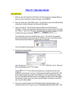


© Copyright 2026