
View/Open - AUC DAR Home - The American University in Cairo
The American University in Cairo The School of Sciences and Engineering Department of Construction and Architectural Engineering PERFORMANCE OF PORTLAND LIMESTONE CEMENT CONCRETE INCORPORATING CHEMICAL AND MINERAL ADMIXTURES A thesis submitted to The Department of Construction and Architectural Engineering in partial fulfillment of the requirements for the degree of Master of Science in Construction Engineering By Sara Mohsen Hussain Ali B.Sc. in Construction Engineering, American University in Cairo, Fall 2011 B.Sc. in Architectural Engineering, American University in Cairo, Fall 2011 Under the Supervision of Dr. Mohamed Nagib Abou-Zeid Professor The Department of Construction and Architectural Engineering The American University in Cairo April 2015 DEDICATION This work is lovingly dedicated to my beloved family in gratitude to their non-stop support, tolerance and patience. I would like also to dedicate this thesis to my lovely father, Mohsen Hussain Ali, and my husband, Mohamed Abdelhafez. They never lost faith in me and I would not have made it without their continuous support, patience, tolerance and motivation. ii ACKNOWLEDGEMENT First and foremost, my sincerest gratitude goes to my supervisor, Dr. Mohamed Nagib Abou Zeid. He has endured the obstacles that I encountered during the course of finalizing my thesis. His guidance and thoughtful advice contributed to formulating the ideas developed during research. He has been always supportive and it was an honor to have Dr. Mohamed Nagib Abou Zeid as my supervisor. I would like to thank Prof. Dr. Omaima Salah Eldin and Dr. Tamer Breakah for their effort and for serving as my examining committee. Special thanks to Dr. Ezzeldin Yazeed, director of the graduate program. I am also very thankful to all the concrete laboratory personnel who helped me during this study. Special thanks to Eng. Rasha Abdel Aziz, Ragab, Fares and Haitham for their tremendous assistance in the laboratory. Also, many thanks to Eng. Samer Abadir and Eng. Sahar for facilitating acquiring the materials needed from Sika company. Moreover, I am very grateful to my father, Mohsen Ali, who has encouraged and supported me throughout the work. Special thanks to my family, my mother, Hanan El-Kassas and my sister. My deepest gratitude to my husband, Mohamed, cannot be expressed by mere words since he has always been supportive. He has been very understanding, patient and kind. This work would not have been possible without Mohamed’s support, patience and assistance. I would like to express my deepest appreciation to my all work mates in Sites International. Special thanks to Dr. Maher Stino and Dr. Laila El Masry for being understanding and supportive. Also, my deepest gratitude is expressed to Eng. Marwa Abdel-Baky for her assistance, flexibility, understanding and support. Many thanks to my friends, Mahy Essam, Doaa Ali and Noha Mayhoub, they never lost faith in me and has always encouraged me during the course of finalizing my thesis. iii ABSTRACT Portland limestone cement, PLC, has been produced by inter-grinding clinker with crushed limestone and gypsum. The crushed limestone introduced in PLC manufacturing as a partial replacement of the clinker serves in conserving energy and reducing CO 2 emissions. Since CO2 is a main greenhouse gas that contributes to global warming, its reduction has gained attention. Therefore, the importance of PLC appears in improving concrete sustainability through reduction in greenhouse gas emissions and energy consumed in the cement industry. Europe, Canada and U.S.A took the lead in developing research studies upon allowing the incorporati on of limestone in Portland cement. Currently, Egypt is taking steps into the production of PLC to promote a sustainable and environmentally friendly concrete. Yet, little work has been conducted on PLC while other international attempts on its incorporation did not tackle heavily it interaction with admixtures. This work aims primarily at investigating the performance of Portland limestone cement concrete incorporating chemical and mineral admixtures. Sixteen concrete mixtures were prepared with various levels of limestone while incorporating plasticizing admixtures and silica fume. The experimental program involved testing Portland cement, fresh concrete and hardened concrete. The tests performed on hardened concrete were, compressive strength, flexural strength, resistance to chloride ion penetration, sulphate and corrosion attacks. Results of this work reveals a somewhat similar behavior of PLC concrete when compared to OPC concrete with regards to compressive and flexural strength; yet, strength decreased with higher incorporation of Portland limestone cement. Furthermore, addition of superplasticizing agent and silica fume had the highest compressive and flexural strength values. Portland limestone concrete outperformed conventional concrete upon exposure to chloride ion penetration. The increase in limestone cement incorporation with the addition of superplasticizer and silica fume admixtures reduced the chloride permeability the most. It also demonstrated a lower mass loss and strength reduction upon exposure to sulphate attack. Lower corrosion risk was attained by PLC concrete compared to conventional concrete. Future work needs to be performed to investigate long term behavior of PLC concrete’s resistance to carbonation, elevated temperatures, freeze and thaw. Effectiveness of other chemical and mineral admixtures such as fly ash and blast furance slag should be examined in order to evaluate PLC’s performance upon their incorporation. Applicators are encouraged to make use of PLC concrete in non-strategic structures in an attempt to improve concrete’s sustainability and alleviate negative environmental impact. iv TABLE OF CONTENTS List of Tables.......................................................................................................... viii List of Figures ........................................................................................................... x Chapter 1 : Introduction ............................................................................................. 1 1.1. Background ..................................................................................................... 1 2.1. Objectives and Scope of Work ........................................................................ 5 Chapter 2 : Literature Review .................................................................................... 6 2.1. Applications of Limestone in the Construction Industry .............................. 6 2.2. Portland limestone cement ........................................................................... 7 2.2.1. 2.3. Research Studies Regarding Portland Limestone Cement ...................... 8 Results of Adding Limestone to Concrete .................................................. 10 2.3.1. Compressive Strength ......................................................................... 10 2.3.2. Resistance to Carbonation ................................................................... 12 2.3.3. Resistance to Chloride Penetration ...................................................... 15 2.3.4. Resistance to Sulphate Attack ............................................................. 16 Chapter 3 : Experimental Work ............................................................................... 20 3.1. Work Strategy ............................................................................................ 20 3.2. Materials .................................................................................................... 20 3.2.1. Portland Cement .................................................................................. 20 3.2.2. Portland Limestone Cement ................................................................ 20 3.2.3. Fine Aggregates .................................................................................. 21 3.2.4. Coarse Aggregates .............................................................................. 22 3.2.5. Water .................................................................................................. 24 3.2.6. Silica Fume ......................................................................................... 24 v 3.2.7. Water Reducing Admixture – Plasticizer ............................................. 24 3.2.8. High Range Rater Reducing Admixture - Superplasticizer .................. 24 3.3. Mixtures Preparation .................................................................................. 24 3.4. Experimental Program ............................................................................... 25 3.4.1. Aggregate Testing ............................................................................... 30 3.4.2. Portland Cement Testing ..................................................................... 30 3.4.3. Fresh Concrete Testing ........................................................................ 33 3.4.4. Hardened Concrete Testing ................................................................. 34 3.4.4.1. Compressive Strength Test ........................................................... 35 3.4.4.2. Flexural Strength Test .................................................................. 35 3.4.4.3. Rapid Chloride Permeability Test ................................................. 37 3.4.4.4. Sulphate Resistance Test .............................................................. 38 3.4.4.5. Corrosion (Cracked Beam) Test ................................................... 38 Chapter 4 : Results and Analysis ............................................................................. 40 4.1. Portland Cement Testing ............................................................................ 40 4.1.1. Normal Consistency of Hydraulic Cement .......................................... 40 4.1.2. Setting Time of Hydraulic Cement ...................................................... 40 4.1.3. Density of Hydraulic Cement .............................................................. 42 4.1.4. Fineness of Hydraulic Cement Using Air Permeability Apparatus ...... 43 4.1.5. Compressive Strength of Hydraulic Cement Mortar ............................ 44 4.2. Fresh Concrete Testing .............................................................................. 45 4.3. Hardened Concrete Properties .................................................................... 48 4.3.1. Compressive Strength of Concrete ...................................................... 48 4.3.1.1. Compressive strength of concrete at 7-day ................................... 52 4.3.1.2. Compressive strength of concrete at 28-day ................................. 54 vi 4.3.1.3. 4.3.2. Compressive strength of concrete at 56-day ................................. 57 Flexural Strength of Concrete ............................................................. 59 4.3.2.1. Flexural strength at 28-day ........................................................... 61 4.3.2.2. Flexural strength at 56-days ......................................................... 64 4.3.2.3. Ratio between 28-day flexural and compressive strength ............. 66 4.3.2.4. Ratio between 56-day flexural and compressive strength ............. 67 4.3.3. Electrical Indication of Concrete’s Ability to Resist Chloride ion penetration ....................................................................................................... 69 4.3.4. Sulphate Resistance ............................................................................. 78 4.3.5. Corrosion ............................................................................................ 84 Chapter 5 : Conclusions and Recommendations ...................................................... 89 5.1. Conclusions ............................................................................................... 89 5.1.1. Portland Cement .................................................................................. 89 5.1.2. Fresh Concrete .................................................................................... 89 5.1.3. Hardened Concrete .............................................................................. 89 5.2. Recommendations for Future Research Work ............................................ 91 5.3. Recommendations for the Construction Industry ........................................ 91 References ............................................................................................................... 93 List of Notations ...................................................................................................... 95 Appendix 1: Rapid Chloride Permeability Test Reports .......................................... 96 vii LIST OF TABLES Table 1-1: Composition of clinker, (Huntzinger, D. N. et al., 2009) .......................... 2 Table 2-1: Binder composition of the produced concretes, (Sotiriadis, K. et al., 2013) ................................................................................................................................ 17 Table 2-2: Deterioration scale and damage observed, (Sotiriadis, K. et al., 2013) ... 17 Table 3-1: Properties of ordinary Portland cement CEM I 42,5 R, (Suez Cement, CEM I 42,5 R data sheet) ........................................................................................ 21 Table 3-2: Properties of Portland limestone cement CEM II /B-L 32,5 R, (Suez Cement, CEM II 32,5 R data sheet) ......................................................................... 21 Table 3-3: Sieve analysis of fine aggregates ............................................................ 22 Table 3-4: Sieve analysis of coarse aggregate .......................................................... 23 Table 3-5: Egyptian Standards used in the testing program ..................................... 26 Table 3-6: Concrete mix proportions ....................................................................... 29 Table 3-7: Aggregate testing .................................................................................... 30 Table 3-8: Portland cement testing .......................................................................... 31 Table 3-9: Fresh concrete testing ............................................................................. 33 Table 3-10: Hardened concrete testing - specimens preparation .............................. 34 Table 3-11: hardened concrete testing ..................................................................... 34 Table 4-1: Normal consistency of hydraulic cement ................................................ 40 Table 4-2: Setting time of hydraulic cement ............................................................ 41 Table 4-3: Initial and final setting time of hydraulic cement .................................... 41 Table 4-4: Density of hydraulic cement ................................................................... 42 Table 4-5: Fineness of hydraulic cement ................................................................. 44 Table 4-6: Compressive strength of hydraulic cement mortar .................................. 44 Table 4-7: Fresh concrete properties ........................................................................ 46 Table 4-8: Average compressive strength at 7, 28 and 56 day ................................. 49 Table 4-9: 7-day compressive strength .................................................................... 52 Table 4-10: 28-day compressive strength................................................................. 55 Table 4-11: 56-day compressive strength................................................................. 57 Table 4-12: Modulus of rupture at 28 and 56-day .................................................... 60 viii Table 4-13: 28-days flexural strength ...................................................................... 62 Table 4-14: 56-day flexural strength ........................................................................ 64 Table 4-15: Ratio between 28-day flexural and compressive strength ..................... 66 Table 4-16: Ratio between 56-day flexural and compressive strength ..................... 68 Table 4-17: Rapid Chloride Permeability test results ............................................... 70 Table 4-18: Chloride permeability classification and legend ................................... 71 Table 4-19: Mass weights before and after exposure to sulphates ............................ 78 Table 4-20: Compressive strength of cubes exposed to sulphates ............................ 82 Table 4-21: Specimens corrosion rates .................................................................... 86 ix LIST OF FIGURES Figure 1-1: Contributions to greenhouse effect (Manne, A., and Richels, R., 1990) . 1 Figure 1-2: Cement manufacturing process, (Huntzinger, D. N. et al., 2009) ............. 3 Figure 1-3: Types of cement produced in Europe, (Hooton, R. D. et al., 2007) ......... 4 Figure 2-1: Crushed stone types in USA, (Carlos, A. et al., 2010) ............................. 6 Figure 2-2: Work methodology, (Beder, F. et al., 2014) .......................................... 10 Figure 2-3: Compressive strength for 0.5 w/c, (Beder, F. et al., 2014) ..................... 11 Figure 2-4: Compressive Strength for w/c of 0.3 with superplasticizer, (Beder, F. et al., 2014) ................................................................................................................. 11 Figure 2-5: Compressive Strength for w/c of 0.3 with superplasticizer and silica fume, (Beder, F. et al., 2014) ................................................................................... 12 Figure 2-6: Depth of carbonation as a function of w/c for concrete produced with PLC, (Hooton, R. D. et al., 2007) ............................................................................ 13 Figure 2-7: Carbonation resistance of PC and PLC concretes, (Dhir, R. K. et al., 2007) ....................................................................................................................... 14 Figure 2-8: Rapid Chloride Migration test setup, (Stanish, K. D. et al.)................... 15 Figure 2-9: DRCM coefficients as a function of water/binder ratio, type of binder and binder dosage on concretes cured 28 days, (Lollini, F. et al., 2014) ......................... 16 Figure 2-10: Concrete specimens after exposure in Sulphate solutions, (Sotiriadis, K. et al., 2013) ............................................................................................................. 18 Figure 2-11: Deterioration degree for the specimens in relation to time, (Sotiriadis, K. et al., 2013) ......................................................................................................... 19 Figure 3-1: Fine aggregates gradation ...................................................................... 22 Figure 3-2: Coarse aggregates gradation .................................................................. 23 Figure 3-3: Illustration of mixture I.D. .................................................................... 25 Figure 3-4: Summary of work methodology ............................................................ 27 Figure 3-5: Experimental program summary ........................................................... 28 Figure 3-6: Preparation and testing normal consistency of cement .......................... 31 Figure 3-7: Setting time of cement by Vicant needle ............................................... 32 Figure 3-8: Preparation for testing the compressive strength of cement ................... 32 x Figure 3-9: Thermometer and slump cone .............................................................. 33 Figure 3-10: Compressive strength specimens ......................................................... 35 Figure 3-11: Flexural strength beams preparation .................................................... 36 Figure 3-12: Flexural strength beam testing ............................................................. 36 Figure 3-13: RCPT specimens’ preparation ............................................................. 37 Figure 3-14: RCPT specimens’ saturation ............................................................... 37 Figure 3-15: Cubes immersed in a sulphate solution ................................................ 38 Figure 3-16: Corrosion test specimen ...................................................................... 39 Figure 4-1: Setting time of hydraulic cement ........................................................... 41 Figure 4-2: Density of hydraulic cement .................................................................. 42 Figure 4-3: Fineness of hydraulic cement ................................................................ 44 Figure 4-4: Compressive strength of hydraulic cement mortar ................................. 45 Figure 4-5: Slump obtained for each mixture ........................................................... 47 Figure 4-6: Unit weight obtained for each mixture .................................................. 47 Figure 4-7: Air content obtained for each mixture ................................................... 48 Figure 4-8: 7, 28, and 56- day compressive strength ................................................ 51 Figure 4-9: 7-day compressive strength vs. admixtures used ................................... 53 Figure 4-10: 7-day compressive strength vs. each mix group................................... 54 Figure 4-11: 28-day compressive strength vs. admixtures used ............................... 55 Figure 4-12: 28-day compressive strength vs. mix group ......................................... 56 Figure 4-13: 56-day compressive strength vs. admixtures used ............................... 58 Figure 4-14: 56-day compressive strength vs. mix group ......................................... 59 Figure 4-15: Flexural strength for each mix group at 28 and 56-day ........................ 61 Figure 4-16: 28-day flexural strength vs. admixtures used ....................................... 62 Figure 4-17: 28-day flexural strength vs. mix group ................................................ 63 Figure 4-18: 56-day flexural strength vs. admixtures used ....................................... 64 Figure 4-19: 56-day flexural strength vs. mix groups .............................................. 65 Figure 4-20: Relationship between 28-day flexural and compressive strength ......... 67 Figure 4-21: Relationship between 56-day flexural and compressive strength ......... 68 Figure 4-22: Rapid Chloride Permeability Test setup .............................................. 69 Figure 4-23: RCPT cells connected to Proove it system .......................................... 69 xi Figure 4-24: Charge passed of each specimen ......................................................... 71 Figure 4-25: Charge passed for each mix group ....................................................... 72 Figure 4-26: Current flow in OPC specimens .......................................................... 75 Figure 4-27: Current flow in PLC 10% specimens ................................................... 75 Figure 4-28: Current flow in PLC 15% specimens ................................................... 76 Figure 4-29: Current flow in PLC 25% specimen .................................................... 76 Figure 4-30: Current flow in each specimen vs. time ............................................... 77 Figure 4-31: Weights of specimens before and after exposure to sulphate ............... 79 Figure 4-32: Mass percentage loss for each specimen .............................................. 80 Figure 4-33: Mass percentage loss for each mix group ............................................ 80 Figure 4-34: Representation of noticed severe damages .......................................... 81 Figure 4-35: Strength retained on cubes exposed to sulphates ................................. 83 Figure 4-36: Strength loss upon exposure to sulphates ............................................ 84 Figure 4-37: Corrosion current density of each mix group ....................................... 86 Figure 4-38: Corrosion current density behavior in each mix group ........................ 87 xii Chapter 1 : Introduction 1.1.Background The construction industry is a major polluting industry. This is due to the significant waste generated during construction and demolitions as well as the noneco-friendly Portland cement industry. Portland cement, a main constituent of concrete, production contributes to a huge release of CO 2 and other greenhouse gases (GHGs), (Naik, T. R., 2005). In other words, one ton of greenhouse gases is produced when manufacturing one ton of Portland cement, (Malotra, qtd. in Naik, 3). Those greenhouse gases are of a global concern because they affect earth’s temperature and contribute to global warming. Figure 1-1 shows the contribution of each gas to global warming and it demonstrates that CO2 is responsible approximately for half the problem (Manne, A., and Richels, R., 1990). Other gases contributions vary. For instance, methane is ranked the second followed by chlorofluorocarbons (CFCs), nitrous oxide, and other. Each contributes with 18, 14, 6 and 13% respectively. Figure 1-1: Contributions to greenhouse effect (Manne, A., and Richels, R., 1990) Since the extensive rise in those emissions threatens the ecosystems on earth, crucial industries started to seek other alternatives that would decrease the CO 2 footprint. For the cement industry, CO2 emissions are released during two processes. 1 First, it is emitted as a by-product during manufacturing the clinker, a main constituent of cement. In other words, the calcination process involves heating calcium carbonate (CaCO 3) in order to induce certain chemical reactions and carbonates are converted to oxides as a result. Second, CO2 is released during cement production by fossil fuel combustion. Thus, to achieve sustainability of cement and concrete researchers proposed replacing percentages of clinker with other alternatives that would reduce CO 2 emissions without compromising the mechanical properties of cement (Huntzinger, D. N. et al., 2009). Portland cement is primarily composed of calcium silicate minerals. Table 1-1 lists the composition of clinker, the main constituent of Portland cement. Manufacturing Portland cement involves many stages. First, raw materials are extracted from quarries and transported to the manufacturing facility. The transported raw materials are then crushed, dry mixed and milled into a fine powder. Then, the powder passes through a preheater to enter a huge rotary kiln that calcinates the material. The rotary kiln transforms the raw materials into clinker at temperature greater than 1400 °C. The output of this process, the clinker, is then cooled and gypsum is added in order to extend the cement setting time. The end product of this process is a very fine mixture that is packed and known as Portland cement (Huntzinger, D. N. et al., 2009). Figure 1-2 shows a general flow diagram of the cement manufacturing process elaborated above. Also, it illustrates the associated inputs and emission during each stage of the process. Table 1-1: Composition of clinker, (Huntzinger, D. N. et al., 2009) 2 Figure 1-2: Cement manufacturing process, (Huntzinger, D. N. et al., 2009) Limestone cement was introduced as partial replacement of the clinker in the cement industry, thereby conserving energy and reducing CO2 emissions. Portland Cement Association performed a study to assess the effectiveness of adding 5% limestone cement with regards to energy conservation and CO 2 emissions reduction. It showed that the addition of 5% of limestone is equivalent to 0.05 tons which “lowers the clinker input to 0.9 tons per ton of cement”. This 5% limestone addition corresponds to a “reduction of 5.26% in the amount of clinker required per ton of cement”. This reduction will result in “reduction of 220,000 mmBtu (million metric British thermal units) per million tons. Those 220,000 mmBtu are equivalent to 9,700 tons of coal or 220 million ft 3 of natural gas. Regarding reduction in carbon dioxide, emissions are set at an average of 1,792.65 lbs per ton of cement. In other words, the decrease in CO 2 emissions is equivalent to 47,147 tons per 1,000,000 tons of cement (Nisbet, M. A., 1996). Therefore, addition of limestone cement started to gain attention for introducing a concrete that would be environmentally friendly. 3 Limestone was produced earlier in 1965 by Heidelberg Cement in Europe for specialty application. In 1987, a draft of the European standard (EN 197) allowed the use of limestone cement. By 2000, the (EN 197-1) provided using all the 27 common types of cement, 4 of which allow higher amounts of limestone. The provided limestone replacement ranges were two; (6 to 20%) and (21 to 35%). According to Figure 1-3, CEM II usage increased from 15% in 1999 to 31.4% in 2004. Additionally, it is considered now the largest type of cement produced (Hooton, R. D. et al., 2007). Attempts in Canada and in the US were different. Canada provided the use of 5% limestone in its standard (CSA A5) since 1983. On the other side, the US had three attempts over a twenty year period. Limestone cement was finally allowed in 2004 in ASTM C150. Then, a task group was formed in 2005 in order to harmonize the AASHTO M85 with ASTM C150 and eliminate differences in cement specifications. Figure 1-3: Types of cement produced in Europe, (Hooton, R. D. et al., 2007) 4 2.1.Objectives and Scope of Work There has been little work reported which focuses on the impact and interaction of using chemical and mineral admixtures with the emergence of Portland limestone cement. This creates a need to tackle such interaction since almost all modern concrete mixtures involve one or more types of admixtures. The objective of this research is to study impact and effectiveness of incorporating chemical as well as mineral admixtures in Portland cement concrete made with limestone cement. Mixtures were tested for slump, unit weight, air content, temperature, compressive strength, flexural strength, permeability and resistance to sulphate and corrosion attacks. Then, the results are compared with the control mix in order to study the influence caused on the concrete properties for each mix. 5 Chapter 2 : Literature Review 2.1. Applications of Limestone in the Construction Industry The availability of limestone in many countries urged researchers and industrial experts to start using it as a substitution for coarse or fine aggregate. For instance, most crushed stone in the USA have been made of limestone since fifty years ago. Therefore, the availability of limestone quarries caused minimal usage of other aggregates in the construction industry. According to Carlos, A. et al. (2010), “the usage of the other aggregates than limestone in USA has been decreasing gradually, but definitely it will not reach zero”. It is also anticipated that production of limestone is expected to increase by more than 20% in 2020. Figure 2-1 shows the types of crushed stone in the USA and the major contribution of limestone in the total availability of crushed stone. In other words, limestone has been used as a substitution for the coarse aggregate because of its availability as a resource. 7% 9% 15% Limestone Granite 69% Taprock Others Figure 2-1: Crushed stone types in USA, (Carlos, A. et al., 2010) Many researchers have been focusing on the use of limestone aggregate in concrete. Others considered its effect on concrete properties when integrated with crushed sand. However, few attempts have been made to use limestone in the cement industry. Poitevin, P. (1999) highlighted that limestone aggregate concrete is durable with regards to acid water attack, sea water attack and sulphate attack. 6 Such properties are inherited from the aggregate characteristics. For instance, high or medium hardness limestone aggregate with low water absorption can be used to produce high strength concrete (Poitevin, P., 1999). Such a mix can have various applications in construction. Poitevin, P. (1999) stated that Boulonnais limestone concrete was used in all the runways of Paris airport. Other applications of limestone concrete mix are in retaining structures and foundations. In addition to those research studies, Menadi, B. et al. (2009) introduced concrete incorporating limestone fines. The influence of limestone fines in crushed sand was then analyzed by experimental procedures to ensure that high percentages did not cause decreases in the physical and mechanical properties of concrete. Concrete samples were prepared and tested to determine their compressive strength, total porosity and water permeability. Regarding compressive strength, some percentages caused an improvement for all the mixtures while 15% of fines influenced strength negatively. The increase in compressive strength caused a sequential increase in the total porosity of all the mixtures. Also, it was found that the water penetration depth was reduced for all concrete mixtures containing limestone fines. 2.2. Portland limestone cement Portland limestone cement, PLC, is similar to ordinary Portland cement in production. It is produced at the same Portland cement manufacturing plants by inter-grinding Portland cement clinker with crushed limestone and gypsum (Cost, V. et al., 2012). Since limestone is softer than clinker, it has a narrower particle size distribution and it takes less energy to be grinded. In other words, the energy required to grind limestone decreases with the increase in limestone content (Hooton, R. D. et al., 2007). Europe, Canada and U.S.A took the lead in using limestone in Portland cement. Limestone has been permitted by the European standard and the Canadian standards since early 1980’s. Then, Europe allowed high percentages of limestone content by 2000. By 2004, the U.S.A allowed the use of 5% of limestone in ASTM C150 and AASHTO M 85 (Hawkins, P. et al.). The growing use of PLC in these 7 countries shall encourage other countries to start improving the sustainability of concrete via the use of PLC (Cost, V. et al., 2012). 2.2.1. Research Studies Regarding Portland Limestone Cement Many research studies have been published to examine the effect of limestone cement on concrete. One of those studies has been done by Dhir, R. K. et al. (2007) to support the notion that limestone contributes to the performance of the concrete. For instance, the mechanical properties of concrete vary according to the level of limestone contribution in the mix. Thus, the research incorporated the usage of limestone in different combinations of Portland cement and limestone. The limestone percentage levels used were 15, 25, 35 and 45%. Then, Portland cement concrete was compared to limestone cement concrete with regards to strength, initial surface absorption, chloride diffusion, carbonation resistance and abrasion resistance. It was found that the strength was similar to that of regular concrete while it tended to decrease with the highest levels of limestone; 35% and 45%. Also, properties like flexural strength and modulus of elasticity showed similar performance to Portland cement concrete, but increasing limestone percentage in the mix showed poorer performance. An enhancement in durability was found for limestone levels up to 25%. Then, both mixtures showed similar behavior in chloride diffusion, carbonation resistance and abrasion resistance. Another study was done by Tsivilis, S. et al. (2002) to analyze the properties of limestone cements and concrete by focusing on three main aspects. The main two features of the research were the limestone effect on the performance of cement and the participation of limestone in the hydration reactions of clinker. Thus, the research starts with discussing the chemical composition of both the clinker and limestone. After inter-grinding both components forming limestone cement, samples of Portland limestone cement with limestone ranges from 10 to 40% were prepared. The samples helped to analyze the particle size distribution of the mixture with regards to the different ranges of limestone. Other concrete designs were tested to analyze the properties of limestone cement concrete and its corrosion behavior. The study concluded that the particle size distribution is connected with the limestone content 8 and fineness. Also, it was found that the limestone cement demanded less water an d indicated a satisfactory strength, significant concrete properties and an improvement in the durability. The addition of limestone percentages enhanced the hydrations reactions of the clinker. Lollini, F. et al. (2014) studied the long term behavior of concrete incorporating limestone cement in order to evaluate it aside from the environmental impacts gained. Portland limestone cement was used to replace Portland cement with percentages 15 and 30%. Furthermore, three different ratios of water/binder were used. For instance, water/binder ratios used were 0.42, 0.46 and 0.61 and binder dosages ranged from 250 to 400 kg/m 3. Testing program included compressive strength according to EN 12390-3 standard, sorptivity test according to EN 13057 and resistance to carbonation. It was concluded that 15% limestone replacement improved the concrete’s behavior when exposed to chloride. Also, the change in water/binder ratio showed influence on the resistivity and strength. However, 30% limestone replacement illustrated a remarkable decrease in all the properties studied. While many research attempts focused on the properties of limestone cement concrete, few contributions discussed the use of pozzolanic mineral admixtures to increase PLC’s resistance against sulphate attacks. Sotiriadis, K. et al. (2013) investigated two factors with regards to concrete’s durability. These factors are the effect of the mineral admixtures used in addition to effect of chlorides on concrete’s deterioration due to sulphate attack. Limestone cement concrete was used in the study with a percentage of 15%. Then, the mineral admixtures were used as a replacement for limestone cement with various percentages ranging from 10 to 50%. In other words, natural pozzolana and fly ash replaced 30% by mass of limestone cement while blast-furance slag and metakaolin replaced 50 and 10% of the limestone used in the mix. After curing, the specimens were immersed in two corrosive solutions and inspected visually while recording mass changes at regular intervals. It was found that “the use of appropriate mineral admixtures in limestone cement concrete retards and inhibits deterioration due to sulphate attack and improves its durability” (Sotiriadis, K. et al., 2013). In this case, fly ash and blast- 9 furance slag were the most effective minerals for improving the resistance of limestone cement concrete against sulphate attack. 2.3. Results of Adding Limestone to Concrete 2.3.1. Compressive Strength Beder, F. et al. (2014) developed a study on PLC to investigate the change in the concrete’s properties with the change in water/binder ratio and the admixtures added. The mixtures were categorized into three main categories; 0% limestone cement concrete, 10% and 15% limestone cement concrete. Each category included three different specimens. Figure 2-2 shows the summary of the specimens developed. The three categories changed in the water to binder ratio used and the admixtures added. Figure 2-2: Work methodology, (Beder, F. et al., 2014) Compressive strength results illustrated that the use of superplasticizer and silica fume in combination with limestone cement concrete have a positive impact on the strength. PLC with admixtures showed a significant improvement in the strength 10 for a 10% dosage of limestone cement. The increase in limestone cement percentage tends to affect the compressive strength negatively with regards to the normal concrete. However, the decrease in the strength can still be compensated for the significant environmental impact of PLC. 45 OPC 10% 15% Compressive Strength (MPa) 40 35 41 39 32 33 37 33 30 28 30 25 35 25 25 20 17 15 10 5 0 3 Days 7 Days 28 Days 56 Days Figure 2-3: Compressive strength for 0.5 w/c, (Beder, F. et al., 2014) 70 Compressive Strength (MPa) 60 OPC 10% 15% 58 54 48 50 40 53 39 38 35 45 41 40 31 30 25 20 10 0 3 Days 7 Days 28 Days 56 Days Figure 2-4: Compressive Strength for w/c of 0.3 with superplasticizer, (Beder, F. et al., 2014) 11 Figure 2-3 and Figure 2-4 shows the effectiveness of superplasticizer addition to limestone cement concrete. The decrease in water to binder ratio accompanied with an addition of superplasticizer increased the strength of the three mixtures. However, 10% PLC results exceeds the other two specimens. Then, OPC’s strength decreases slightly from 10% PLC. Figure 2-5 illustrates that the 10% PLC takes the lead in the strength with the addition of silica fume. On the other side, OPC and 15% PLC are affected negatively. 60 OPC 10% 15% Compressive Strength (MPa) 50 49 44 41 39 40 36 33 32 32 37 33 30 23 22 20 10 0 3 Days 7 Days 28 Days 56 Days Figure 2-5: Compressive Strength for w/c of 0.3 with superplasticizer and silica fume, (Beder, F. et al., 2014) 2.3.2. Resistance to Carbonation Hooton, R. D. et al. (2007) investigated the behavior of PLC concrete specimens when being exposed outdoors. Specimens were moist-cured for 1 day then stored in an outdoor-sheltered exposure site for five years. Figure 2-6 shows that the carbonation depth of PLC specimen increased with the increase in limestone content. In other words, specimens with 5% limestone incorporation demonstrated 12 similar behavior to OPC. Other specimens with 25% limestone obtained the highest carbonation depth. With the increase in limestone incorporation, the carbonation depth increases even when mineral admixtures are added. For instance, 30% of fly ash was added to specimens containing 28% of PLC. The addition of fly ash reduced the carbonation depth compared to 25% PLC specimens. Yet, the carbonation depth attained was still higher than control and 5% limestone specimens. Figure 2-6: Depth of carbonation as a function of w/c for concrete produced with PLC, (Hooton, R. D. et al., 2007) Dhir, R. K. et al. (2007) examined the performance of limestone cement concrete through studying the properties of concrete with limestone cement conten t up to 45%. The levels of limestone cement used in this research were high. For instance, the cement combinations used were 0% limestone cement, 15, 25 and 35%. Then, 45% limestone dose was used which is higher than the allowed limestone content in EN 197-1. Two carbonation tests were carried out in this research. The first test was performed according to the European Committee for Standardization (CEN). This involved storing 100x100x500 mm prisms in a 0.035% CO 2 13 environment at 20°C and 65% RH for 1 year. Another accelerated test was carried out on 100 mm cubes by storing them in a 4% CO 2 environment at 20°C and 65% RH for twenty weeks. Both test results are shown in Figure 2-7. Figure 2-7: Carbonation resistance of PC and PLC concretes, (Dhir, R. K. et al., 2007) “The data show general agreement with related work in terms of the effect of LS level on the property at equal w/c ratio and of the relationship with compressive strength”, (Dhir, R. K. et al., 2007). Figure 2-7 (a) indicates the carbonation depth for the different levels of LS over a range of w/c ratios. The behavior of each group is almost similar with minor differences. However, the increase in LS levels is accompanied with an increase in the carbonation depth. Figure 2-7 (b) suggests a strong correlation between the carbonation resistance and the compressive strength. In other words, “the carbonation resistance of both PC and PLC concretes increased with strength while the curves generally followed a similar relationship, they were slightly offset”. (Dhir, R. K. et al., 2007) 14 2.3.3. Resistance to Chloride Penetration Lollini, F. et al. (2014) study focused on assessing PLC’s resistance to chloride and carbonation penetration. For instance, the effect of limestone percentage, water/binder ratio and cement content was studied in order to investigate the durability behavior of limestone to the resistance to chloride penetration. Resistance to chloride penetration was tested with the Rapid Chloride Migration (RCM) accelerated test according to NT-BUILD 492 standard. In other words, Figure 2-8 shows that “specimens were laid on an inclined plastic support and placed in a container with a 10% NaCl solution, whilst a chloride free solution was poured inside a plastic tube mounted coaxially to them”. + Potential (DC) – Rubber sleeve Plastic stud Specimen Plastic support Figure 2-8: Rapid Chloride Migration test setup, (Stanish, K. D. et al.) The specimens are split axially at the end of the test and sprayed with a solution to indicate the chloride penetration depth Xm. Then, the chloride diffusion coefficient D RCM is calculated from an equation given the gas constant, the average temperature in the solution and time. Figure 2-9 indicates that a replacement of 15% limestone influences positively the diffusion coefficient. For instance, the diffusion coefficient for 15% PLC was 19 x 10 -12 m2/s compared to that of OPC, 12 x 10 -12 15 m2/s. It is also noted that the coefficient increased by the increase of limestone percentages in concrete. By 30% limestone replacement, the diffusion coefficient is remarkably increased to reach 38 x 10 -12 m2/s Figure 2-9: DRCM coefficients as a function of water/binder ratio, type of binder and binder dosage on concretes cured 28 days, (Lollini, F. et al., 2014) 2.3.4. Resistance to Sulphate Attack A research study was done by Sotiriadis, K. et al. (2013) to investigate the effect of mineral admixtures on PLC’s deterioration due to sulphate attack. The specimens were prepared by replacing an amount of limestone cement with each admixture used. For instance, natural pozzolana, fly ash, blast furnace slag and metakaolin are all added to the concrete by replacing a specific percentage from limestone as illustrated in Table 2-1. Samples of 100 mm cubes were prepared. A group of specimens was stored in water as a reference while another was stored in two corrosive solutions for two years. Such solutions were prepared using commercial NaCl and MgSO 4.7H2O salts 16 and they were replaced every two months. Then, visual inspection was performed in addition to recording of any changes in the specimens mass. Furthermore, “all significant modifications such as changes in surface color and texture, formation of coatings, deterioration, expansion and cracking were recorded” (Sotiriadis, K. et al., 2013). Table 2-1: Binder composition of the produced concretes, (Sotiriadis, K. et al., 2013) Deterioration started to appear first in LC1 specimens by the fifth month while other specimens with mineral admixtures started to deteriorate by the seventh or the eighth month. For instance, Figure 2-10 indicates the deterioration degree caused by the sulphate solution for each mix during the exposure period. This illustrates that LC1 is the most damaged specimen followed by LSC and LPC. In order for the researchers to quantify the damage, a deterioration scale with a description of the damage observed was introduced as a measure for the regular visual inspection done, Table 2-2. Table 2-2: Deterioration scale and damage observed, (Sotiriadis, K. et al., 2013) 17 Regarding the changes in mass, it was found that the LC1, LSC and LPC specimens’ mass started to decrease after an exposure period of 11, 19 and 20 months, respectively. Also, it was observed that LC1 showed a significant mass loss in comparison with other specimens containing mineral admixtures. Figure 2-11 supports the conclusion that mineral admixtures improved the performance of specimens subjected to sulphate attack. Furthermore, specimens containing fly ash and metakaolin performed the best with regards to other mineral admixtures. Figure 2-10: Concrete specimens after exposure in Sulphate solutions, (Sotiriadis, K. et al., 2013) 18 The visual inspection shows that LC1 samples demonstrated severe damage compared to other specimens. Furthermore, it obtained the highest deterioration degrees while other specimens with mineral admixtures had lower deterioration degree. The performance of specimens with mineral admixtures added varied, yet they were no significant variations noticed. The general trend was that the mineral admixtures used, reduced the deterioration degree of specimens. Figure 2-11: Deterioration degree for the specimens in relation to time, (Sotiriadis, K. et al., 2013) 19 Chapter 3 : Experimental Work 3.1. Work Strategy The experimental program of this study was designed to investigate the influence of chemical and mineral admixtures when added to Portland limestone cement concrete. This can be concluded by studying the mechanical properties of the prepared specimens. Specimens were grouped according to their limestone cement content. For instance, limestone content in the first group was 0% then 10%, 15% and 25% respectively. Then, various combinations of admixtures were added to form a total of 16 different mixtures. In other words, each group contained other 4 mixtures according to the type of admixture added. Admixtures used were plasticizer, superplasticizer and a combination of 10% silica fume and superplasticizer. 3.2. Materials Several materials were obtained to conduct the experimental work. Two types of cement were acquired; CEM I and CEM II in addition to other constituents of concrete. Both types of cement were obtained from Suez Cement company. The admixtures used were plasticizer, superplasticizer and silica fume. These admixtures were all obtained from Sika company. 3.2.1. Portland Cement Ordinary Portland cement CEM I 42,5 R was used in the specimens preparation. It was procured from Suez Cement company and complies with both Egyptian (ES 4756/1 2013) and international (EN 197/1-2011) standards. Table 3-1 illustrates the properties of the cement type used. 3.2.2. Portland Limestone Cement Portland limestone cement CEM II /B-L 32,5 R was used in this study with a dosage of 10%, 15% and 25%. It was acquired from Suez Cement company complies with both Egyptian (ES 4756/1-2013) and international (EN 197/1-2011) standards. According to Suez 20 Cement’s product sheet, this cement type contains clinker for mechanical strength, limestone to improve the performance and gypsum to control the setting time. Table 3-1: Properties of ordinary Portland cement CEM I 42,5 R, (Suez Cement, CEM I 42,5 R data sheet) Property Chemical analysis Strength Fineness Setting time Product Data Loss of ignition Insoluble Residue Sulphate content (as SO3) Chloride content (Cl) 2 day 7 day 28 day Blain Initial 3.5% 0.3% 3.04% 0.02% 30.2 MPa 41 MPa 51.7 MPa 3550 cm2/g 160 min EN 197-1 Standard values Min Max 5% 5% 4% 0.1% 20 MPa 42.5 MPa 62.5 MPa 60 min - Table 3-2: Properties of Portland limestone cement CEM II /B-L 32,5 R, (Suez Cement, CEM II 32,5 R data sheet) Chemical analysis Strength Fineness Setting time Property Sulphate content (as SO3) Chloride content (Cl) 2 day 28 day Blain Initial Product Data 2.07% 0.023% 21.7 MPa 38.4 MPa 5200 cm2/g 02:20 h:min 3.2.3. Fine Aggregates Sand was obtained to be used in the specimens’ preparation. Sieve analysis was performed to the aggregate according to ASTM C 136-06. The fineness modulus was found to be 2.99 and a bulk specific gravity of 2.55. The results obtained from the sieve analysis 21 are tabulated in Table 3-3. Furthermore, Figure 3-1 shows the gradation curve concluded from the percentage passing in the sieve analysis. Table 3-3: Sieve analysis of fine aggregates Sieve Size #4 #8 #30 #50 #100 #200 pan Weight Retained (g) 22.6 28.3 80.0 425.0 175.6 19.4 5.5 Weight Retained % 2.3 2.8 8.0 42.5 17.6 1.9 0.6 Cumulative Weight Retained (g) 22.6 50.9 130.9 555.9 731.5 750.9 756.4 Cumulative Weight Retained % 2.3 5.1 13.1 55.6 73.2 75.1 75.6 % Passing 97.7 94.9 86.9 44.4 26.9 24.9 24.4 120 100 % Passing 80 60 40 20 0 #4 #8 #30 #50 #100 Sieve size/No. #200 pan Figure 3-1: Fine aggregates gradation 3.2.4. Coarse Aggregates Crushed dolomite was obtained to be used in the specimens’ preparation. Sieve analysis was performed to the aggregate according to ASTM C 136-06. The bulk specific 22 gravity was calculated to be 2.58 while the absorption percentage was 1.64%. The results obtained from the sieve analysis are tabulated in Table 3-4. Furthermore, Figure 3-2 shows the gradation curve concluded from the percentage passing in the sieve analysis. Table 3-4: Sieve analysis of coarse aggregate Sieve Size Weight Retained (g) Weight Retained % 1.5" 1" 3/4" 1/2" 3/8" #4 #8 pan 0.0 0.0 105.6 515.7 253.3 125.4 0.0 0.0 0.0 0.0 10.5 51.5 25.3 12.5 0.0 0.0 Cumulative Weight Retained 0.0 0.0 105.6 621.3 874.6 1000.0 1000.0 1000.0 Cumulative Weight Retained 0.0 0.0 5.3 31.1 43.7 50.0 50.0 50.0 % Passing 100.0 100.0 94.7 68.9 56.3 50.0 50.0 50.0 120 100 % Passing 80 60 40 20 0 1.5" 1" 3/4" 1/2" 3/8" Sieve size/No. #4 #8 Figure 3-2: Coarse aggregates gradation 23 pan 3.2.5. Water Tap water was used in mixing, curing and any cleaning activities. 3.2.6. Silica Fume Silica fume was obtained from Sika company with a market name Sika fume. It contains extremely fine (0.1 µm) latently reactive silicon dioxide SO2 with a bulk density of 300 kg/m3. Its appearance is a grey powder and packaged in 5 kg packs. 3.2.7. Water Reducing Admixture – Plasticizer Water reducing agent was procured from Sika company with a market name Plastiment ®-RX/SR. It’s a liquid set retarding concrete admixture which complies with ASTM C-494 type A. It comes in a brown liquid appearance with a density of 1.170±0.005 kg/l. The specified optimum dosage for use is 0.2-0.8% by weight of cement. Also, it is added to the mixing water prior to its addition to the aggregates. 3.2.8. High Range Rater Reducing Admixture - Superplasticizer High range water reducing agent was procured from Sika company with a market name Sikament®-NN. It’s a highly effective liquid super-plasticizer concrete admixture which complies with ASTM C-494 type F. It comes in a brown liquid appearance with a density of 1.200±0.005 kg/l. The specified optimum dosage for use is 0.6-3% by weight of cement. Also, it is added to the mixing water prior to its addition to the aggregates. 3.3. Mixtures Preparation As illustrated earlier, sixteen mixtures were prepared in four groups with different cement content for each group and a 0.4 water/cement ratio was used for all. Then, each group includes four mix designs incorporating different admixtures. For instance, the first mix in each group has a plasticizer addition. The second, third and fourth mixtures has superplasticizer, superplasticizer with 10% silica fume and superplasticizer with 15% silica fume. The detailed mix proportions used are indicated below in Table 3-6. The first mixture group was the control one; OPC with different admixtures incorporated for each mix as explained above. Then, the second, third and fourth 24 incorporated limestone cement with the admixtures added. Those limestone cement dosages were 10, 15 and 25% respectively. The sixteen mixtures were given an I.D. based on their content. The I.D. consists of three indices. The first index identifies the type of cement used, either ordinary Portland cement or Portland limestone cement. Then, the type of chemical admixture is specified in the second index, either plasticizer or superplasticizer followed by the mineral admixture index, if added. To further illustrate, Figure 3-3 shows how each mixture is indexed. For instance, “OPC” or “PLC” represents the type of cement, “S” or “SP” is for the plasticizer or superplasticizer used followed by “S10” or “S15” in case silica fume is added. OPC - - SP S10 Mineral admixture index and dosage used (if any) Cement type index Chemical admixture index Figure 3-3: Illustration of mixture I.D. 3.4. Experimental Program Four groups of mixtures were prepared with different limestone cement incorporation. The first group contains zero percent limestone followed by ten, fifteen and twenty-five percent respectively. Then, each group has four different mix designs based on the added admixtures. Admixture addition varies from using plasticizer to superplasticizer, superplasticizer with ten percent of silica fume and finally superplasticizer with fifteen percent of silica fume for each group. Figure 3-4 illustrates the summary of the main four groups and the sub-mixtures designed for each. 25 The experimental program has four main classifications for the tests performed; aggregate testing, Portland cement testing, fresh and hardened concrete testing. The tests were conducted according to the ASTM and Egyptian standards. Figure 3-5 shows a brief summary of the tests performed and Table 3-5 shows their corresponding Egyptian standards. Table 3-5: Egyptian Standards used in the testing program Testing Program Aggregate Testing Cement Testing Fresh Concrete Testing Hardened Concrete Testing 26 Code No. ES 1109 ES 2421 ES 1658-2 ES 1658-9 Portland Limestone Cement Mixtures Portland Limestone Cement Concrete: 0% Control Portland Limestone Cement Concrete: 10% Portland Limestone Cement Concrete: 15% Portland Limestone Cement Concrete: 25% Plasticizer - "A" Plasticizer - "A" Plasticizer - "A" Plasticizer - "A" Superplasticizer - "F" Superplasticizer "F" Superplasticizer - "F" Superplasticizer - "F" Superplasticizer + silica fume 10% Superplasticizer + silica fume 10% Superplasticizer + silica fume 10% Superplasticizer + silica fume 10% Superplasticizer + silica fume 15% Superplasticizer + silica fume 15% Superplasticizer + silica fume 15% Superplasticizer + silica fume 15% Figure 3-4: Summary of work methodology 27 Testing Aggregates Testing • Sieve analysis for fine aggregates Portland Cement Testing Fresh Concrete Testing Hardened Concrete Testing Normal consistency Setting time Slump Compressive strength Flexural strength Density Fineness Unit Weight Rapid chloride permeability Sulphate resistance Air Content Corrosion • Sieve analysis for coarse aggregates • Density • Relative density • Absorption of fine agg. • Absorption of coarse agg. Compressive Strength Temperature Figure 3-5: Experimental program summary 28 Table 3-6: Concrete mix proportions Mix No. Mix I.D. 1 2 3 4 5 6 7 8 9 10 11 12 13 14 15 16 OPC-P OPC-SP OPC-SP-S10 OPC-SP-S15 PLC10-P PLC10-SP PLC10-SP-S10 PLC10-SP-S15 PLC15-P PLC15-SP PLC15-SP-S15 PLC15-SP-S15 PLC25-P PLC25-SP PLC25-SP-S25 PLC25-SP-S25 Portland PLC Portland Coarse Fine Water Limestone Plasticizer Superplasticizer content Cement Aggregate Aggregate (kg) cement (kg/m3) (kg/m3) 3 3 (%) (kg/m3) (kg/m ) (kg/m ) (kg/m3) 0% 10% 15% 25% 168 168 151.2 142.8 151.2 151.2 151.2 151.2 142.8 142.8 142.8 142.8 134.4 134.4 134.4 134.4 420 420 378 357 378 378 378 378 357 357 357 357 336 336 336 336 0 0 0 0 42 42 42 42 63 63 63 63 84 84 84 84 1184 1184 1184 1184 1184 1184 1184 1184 1184 1184 1184 1184 1184 1184 1184 1184 29 578.2 578.2 655.1 693.5 655.1 655.1 655.1 655.1 693.5 693.5 693.5 693.5 731.9 731.9 731.9 731.9 2.1 0 0 0 2.1 0 0 0 1.8 0 0 0 1.7 0 0 0 0 6.3 6.3 6.3 0 5.7 5.7 5.7 0 5.4 5.4 5.4 0 5.1 5.1 5.1 Silica Fume (kg/m3) 0 0 42.0 63.0 0 0 37.8 56.7 0 0 35.7 53.6 0 0 33.6 50.4 3.4.1. Aggregate Testing The coarse and fine aggregates used were tested the below list in Table 3-7 according to the ASTM standards. Table 3-7: Aggregate testing Test ASTM reference Sieve analysis of fine and coarse aggregates ASTM C136 Density, relative density (specific gravity), and absorption of fine aggregate ASTM C128 Density, relative density (specific gravity), and absorption of coarse aggregate ASTM C127 3.4.2. Portland Cement Testing Portland cement used in the study was tested the following list of tests in Table 3-8 according to the ASTM standards. Normal consistency test was performed in order to determine the water amount required to prepare the cement pastes for testing. Weight of water was varied until the plunger penetration is 10±1 mm below the surface of the paste. Also, setting time test was conducted in order to determine the initial and final setting time of the hydraulic cement types used. Penetration of the 1 mm needle is determined at 15-minute interval and recorded. Density of hydraulic cement was determined using Le Chatelier flask while the fineness test was conducted using the air permeability apparatus. The compressive strength of hydraulic cement mortar used in the study is determined for ages 3, 7, 28 and 56-day. Three cubes of each mortar type were cast, cured and tested for the specified ages. Figure 3-6 through Figure 3-8 show the preparations required for the normal consistency, setting time, and compressive strength tests for the Portland cement used in this research. 30 Table 3-8: Portland cement testing Test ASTM reference Normal consistency of hydraulic cement ASTM C187 Time of setting of hydraulic cement by Vicant needle ASTM C191 Density of hydraulic cement ASTM C188 Fineness of hydraulic cement using air permeability apparatus ASTM C204 Compressive strength of hydraulic cement mortar using 50 mm cube specimens ASTM C109 Figure 3-6: Preparation and testing normal consistency of cement 31 Figure 3-7: Setting time of cement by Vicant needle Figure 3-8: Preparation for testing the compressive strength of cement 32 3.4.3. Fresh Concrete Testing Table 3-9 shows the fresh concrete properties that were tested during concrete preparation. Figure 3-9 shows some of the apparatus used in testing the properties of fresh concrete. The slump cone was used to measure the slump of each mixture while the thermometer was used to determine the temperature. Table 3-9: Fresh concrete testing Test ASTM reference Slump of hydraulic cement concrete ASTM C143 Air content of freshly mixed concrete by the pressure method ASTM C231 Temperature of freshly mixed hydraulic cement concrete ASTM C1064 Density (unit weight), yield and air content (gravimetric) of concrete ASTM C138 Figure 3-9: Thermometer and slump cone 33 3.4.4. Hardened Concrete Testing Hardened concrete properties were examined by investigating compressive strength, flexural strength, resistance to chloride ion penetration, resistance to sulphate attack and behavior in a corrosive environment. The preparations required for each test and the age of testing is illustrated in Table 3-10. Furthermore, some of the standards used are summarized in Table 3-11. Table 3-10: Hardened concrete testing - specimens preparation Test Compressive strength Flexural strength Sulfate resistance test Rapid chloride permeability test Corrosion (Cracked Beam) test Specimen Dimensions Type (mm) L 150 Cubes W 150 H 150 L 750 W 150 Beams H 150 L 50 Cubes W 50 H 50 H 50.8 Disks D 100 L 750 Reinforced W 150 beams H 150 Age of Testing Samples No./Mix Total Samples No. 7-day 28-day 56-day 9 144 28-day 56-day 4 64 wet and dry cycles 6 96 28-day 1 16 wet and dry cycles 1 16 Table 3-11: hardened concrete testing Test ASTM reference Compressive strength of concrete BS 1881-116 Flexural strength of concrete ASTM C293 Electrical indication of concrete’s ability to resist Chloride ion penetration ASTM C1202 34 3.4.4.1. Compressive Strength Test Nine cubes, (150x150x150) mm, were prepared for each mix in order to study their developed compressive strength at 7, 28 and 56-day according to BS 1881-116. Thus, a total of one hundred and forty four cubes were cast for the compressive strength test and some of these specimens are shown in Figure 3-10. Figure 3-10: Compressive strength specimens 3.4.4.2. Flexural Strength Test Four beams, (750 x 150 x 150) mm, were prepared for each mix in order to investigate their 28-day flexural strength according to ASTM C293. Figure 3-11 shows some of the beams cast for the test while Figure 3-12 illustrates the beam when tested using the ELE machine. 35 Figure 3-11: Flexural strength beams preparation Figure 3-12: Flexural strength beam testing 36 3.4.4.3. Rapid Chloride Permeability Test Rapid chloride permeability test was performed according to ASTM C1202. Cylindrical concrete specimens with a 100 mm diameter and 50 mm thickness were cast and cured for 28-day. Figure 3-13 shows the preparations of the samples required to run the test. Then, specimens were accurately sharpened and water saturated for each test run. Figure 3-13: RCPT specimens’ preparation Figure 3-14: RCPT specimens’ saturation 37 3.4.4.4. Sulphate Resistance Test Six cubes, (50 x 50 x 50) mm, were saw cut from (150 x 150 x 150) mm cubes for each mix in order to evaluate the concrete’s behavior to sulphate attack. The cubes masses were recorded then immersed in a saturated magnesium sulphate (MgSO4) solution for six weeks, Figure 3-15. Each week the cubes were washed, oven dried and reweighed. Then the mass loss was calculated due to sulphate exposure. Furthermore, the compressive strength of the cubes subjected to sulphates was obtained and compared with their replicas that were cured during the testing duration. Figure 3-15: Cubes immersed in a sulphate solution 3.4.4.5. Corrosion (Cracked Beam) Test The objective of this test is to model the corrosion process occurring to steel reinforcement. A total of sixteen reinforced beams, (750 x 150 x 150) mm, were prepared to conduct the test. The reinforcement used was 3 12 mm with a concrete cover of 38 mm from top and 25 mm from bottom. Then, a crack width of 0.5 mm 38 was introduced while casting the reinforced beams in order to simulate the corrosion process. This crack was covered with a glass bath of a saturated NaCl solution to generate galvanic cells between the upper and lower reinforcement. The specimen’s preparation is shown in Figure 3-16. 0.5 mm wide crack 150 mm 750 mm Figure 3-16: Corrosion test specimen The three steel bars extended outside the beam dimensions in order to be used for voltage and current measurements during the test. They were connected to a 10 ohm resistance. Then, the average voltage and current readings in the upper and lower are measured using a voltmeter and an ammeter. 39 Chapter 4 : Results and Analysis The experimental work conducted has three main categories, Portland cement testing, fresh concrete testing and hardened concrete testing. The results of each testing group are demonstrated and analyzed below. 4.1. Portland Cement Testing In this study, ordinary Portland cement and Portland limestone cement were used. Furthermore, Portland limestone cement was used in three dosages, 10, 15 and 25% in order to evaluate their properties. 4.1.1. Normal Consistency of Hydraulic Cement The water weights of each cement type used are obtained and listed Table 4-1. The percentage required of normal consistency is then calculated using the following equation. Weight of water % Required of normal consistency = x 100 Weight of cement (Eq. 4-1) Table 4-1: Normal consistency of hydraulic cement Cement Type PLC % Weight of water (g) Weight of cement (g) % required of normal consistency OPC PLC PLC PLC 0 10% 15% 25% 164.0 190.7 213.2 246.0 650 650 650 650 25.2% 29.4% 32.8% 37.9% 4.1.2. Setting Time of Hydraulic Cement Table 4-2 lists the setting time recorded for each cement type used at 15minute interval. Figure 4-1 illustrates that dosages of Portland limestone cement tend to cause a decrease in the initial and final setting times. Also, the setting time is affected by 40 the fineness of the limestone itself. In other words, “initial and final set times were found to decrease as fineness increased”,(Hooton, R. D. et al., 2007). For example, fineness tends to increase with the increase in the limestone cement percentage. Thus, the general consensus developed by researchers regarding the relationship between fineness and setting time of Portland cement is found to be accurate. Table 4-2: Setting time of hydraulic cement Cement Time OPC PLC 10% PLC 15% PLC 25% 0 15 30 45 60 75 90 105 120 135 150 165 180 195 41 42 40 36 40 38 36 36 36 38 32 34 33 34 30 27 26 28 29 16 22 20 24 18 19 15 14 8 17 13 13 5 15 8 6 4 9 8 5 1 6 4 3 0 2 3 0 Table 4-3: Initial and final setting time of hydraulic cement Setting Time Cement Type Initial (min) 62 75 69 45 Penetration (mm) OPC PLC 10% PLC 15% PLC 25% Final (h:min) 03:15 03:00 02:45 02:30 45 40 35 30 25 20 15 10 5 0 OPC PLC 10% PLC 15% PLC 25% 0 50 100 150 Time (min) 200 250 Figure 4-1: Setting time of hydraulic cement 41 1 0 0 4.1.3. Density of Hydraulic Cement This test was performed in an attempt to determine the density of the different types of cement used in this study. Density of cement was calculated using the following equation, with a mass of cement equivalent to 64 grams. Table 4-4 lists the acquired density for each types of cement used. Density of cement= Mass of cement Volume of cement (Eq. 4-2) Table 4-4: Density of hydraulic cement Cement Type OPC PLC PLC PLC Portland Limestone Cement % 0 10% 15% 25% 3.15 Volume (cm3) 20.6 21.4 21.7 22.1 Density (g/cm3) 3.11 2.99 2.96 2.89 3.11 Density (g/cm3) 3.10 3.05 2.99 3.00 2.96 2.95 2.89 2.90 2.85 2.80 2.75 OPC PLC 10% PLC 15% Cement type PLC 25% Figure 4-2: Density of hydraulic cement Test results obtained in Figure 4-2 suggested that limestone incorporation used tend to affect the cement density negatively. In other words, reduction in the cement’s density was noticed with the increase in limestone incorporation. 42 4.1.4. Fineness of Hydraulic Cement Using Air Permeability Apparatus The purpose of this test is to determine the fineness of the cement types used in the research. The total surface area of each cement type used will be quantified in cm2/g. The weight of the cement samples are calculated using the following equation. Weight of cement ρ V 1 ε (Eq. 4-3) Where: ρ is the density of the sample in g/cm 3 V is the volume of the cell = 1.817 cm 3 ε is the desired porosity of cement (0.5±0.005) Then, time intervals are recorded in seconds and used as a parameter in the following equation to calculate the surface area of the cement. S= Ss T Ts (Eq. 4-4) Where: Ts = 60.69 sec and Ss = 3460 cm2/g As explained earlier, PLC is easier to grind than clinker. Also, it has a narrower particle size distribution. This is directly reflected in the fineness results obtained for OPC and PLC specimens. Figure 4-3 shows that the fineness of cement increases gradually with the increase in limestone cement content. For instance, 25% of PLC obtained the highest fineness 4893 cm 2/g while OPC obtained 3339 cm 2/g. 43 Table 4-5: Fineness of hydraulic cement Cement Type Portland Limestone Cement % Weight (g) Time (S.) Surface Area (cm2/g) OPC PLC PLC PLC 0 10% 15% 25% 2.82 2.71 2.68 2.62 56.5 79.7 92.2 121.4 3339 3964 4265 4893 Blaine Fineness (cm2/g) 6000 4893 5000 3964 4000 4265 3339 3000 2000 1000 0 OPC PLC 10% PLC 15% Cement type PLC 25% Figure 4-3: Fineness of hydraulic cement 4.1.5. Compressive Strength of Hydraulic Cement Mortar The average compressive strength for each age is calculated and tabulated as follows, Table 4-6. Table 4-6: Compressive strength of hydraulic cement mortar Cement type OPC PLC 10% PLC 15% PLC 25% Compressive strength (MPa) 3-day 35.1 31.3 32.7 26.5 7-day 41.2 36.6 38.5 33.4 44 28-day 43.4 40.2 39.4 36.4 56-day 44.8 42.4 41.0 38.3 Figure 4-4 shows that compressive strength decreased with the increase in limestone content. This decrease becomes major with the highest limestone content used which is 25%. Other two dosages tend to behave similarly. For instance, the difference between 10 and 15% dosages was not significant for almost all the testing ages. Furthermore, the strength decrease due to 10 and 15% PLC replacement was similar for all testing ages. In other words, 10 or 15% Portland limestone cement replacement does not reduce the compressive strength significantly. Generally, Portland limestone cement replacement demonstrated close properties to ordinary Portland cement. Additionally, such limestone replacement would help having an environmentally friendly concrete. 50 Compressive Strength (MPa) 45 40 35 30 OPC 25 PLC 10% 20 PLC 15% 15 PLC 25% 10 5 0 3-Day 7-Day 28-Day 56-Day Age Figure 4-4: Compressive strength of hydraulic cement mortar 4.2. Fresh Concrete Testing Fresh concrete properties are examined in order to investigate the effect of admixtures added to PLC on workability, unit weight, air content and temperature. Table 4-7 lists the fresh concrete properties for each mix. 45 The slump obtained ranged from 0 to 60 mm and specimens with the highest PLC and silica fume content obtained in most cases a zero slump, Figure 4-5. Results of unit weight showed a gradual increase for 10 and 15% PLC followed by a decrease with 25% PLC, Figure 4-6. The maximum air content obtained in all was 3.63% in OPC-P specimen while its minimum value was 0.59% for PLC10-SP-S10, Figure 4-7. It was also noticed that specimens with silica fume percentage showed less air content compared to those with plasticizer or superplasticizer additions. Additionally, temperature of all specimens was found to be higher than the specified room temperature due to heat of hydration. Table 4-7: Fresh concrete properties Mix No Mix ID Mix 1 Mix 2 Mix 3 Mix 4 Mix 5 Mix 6 Mix 7 Mix 8 Mix 9 Mix 10 Mix 11 Mix 12 Mix 13 Mix 14 Mix 15 Mix 16 OPC-P OPC-SP OPC-SP-S10 OPC-SP-S15 PLC10-P PLC10-SP PLC10-SP-S10 PLC10-SP-S15 PLC15-P PLC15-SP PLC15-SP-S10 PLC15-SP-S15 PLC25-P PLC25-SP PLC25-SP-S10 PLC25-SP-S15 Type of Cement OPC PLC 10% PLC 15% PLC 25% Slump (mm) 50 25 20 15 55 20 0 0 60 10 10 0 50 15 0 0 46 Unit weight (kg/m3) 2406 2426 2439 2430 2447 2450 2462 2470 2476 2460 2440 2408 2392 2371 2354 2350 Air content % 3.63 2.18 3.11 1.98 3.81 2.71 0.59 0.75 2.98 2.61 1.53 0.72 2.13 1.46 1.3 1.02 Temperature (°C) Mix Room 29 29 28 26 27 25 25 27 27 25 24 25 25 26 28 27 26 26 24 24 23 23 23 26 26 22 22 23 22 24 24 24 70 60 60 Slump (mm) 50 55 50 50 40 30 20 25 20 10 20 15 15 0 0 10 10 0 0 Specimen ID Figure 4-5: Slump obtained for each mixture 2500 2480 Unit Weight (kg/m3) 2460 2440 2420 2400 2380 2360 2340 2320 2300 2280 Specimen ID Figure 4-6: Unit weight obtained for each mixture 47 0 0 4.5 4 Air Content (%) 3.5 3 2.5 2 1.5 1 0.5 0 Specimen ID Figure 4-7: Air content obtained for each mixture 4.3. Hardened Concrete Properties The results of hardened concrete properties will be presented and studied in this section. The following experimental work was conducted in order to study the influence of chemical and mineral admixtures on the behavior of PLC concrete. For this purpose, the compressive strength, flexural strength, resistance to chloride penetration, sulphate attack as well as corrosion were all investigated and thoroughly analyzed. 4.3.1. Compressive Strength of Concrete The average compressive strength for each mix was obtained for 7, 28 and 56day and tabulated in Table 4-8. Then, each testing age result will be arranged and tabulated once for each testing age and for all the results in order to evaluate the effectiveness of the admixtures added on each mixture and on each one of the four mix groups; OPC, PLC 10, 15 and 25%. Standard deviation is calculated for each testing age in order to get an idea about how close the three results to one another. Table 4-8 shows that the highest 48 standard deviation obtained at 7-day strength was 8.07 while the lowest was 0.13. For 28-day strength, the highest standard deviation was 8.32 and the lowest was 0.64 while at 56-day it was 10.83 and 1.47. The calculated standard deviation varied in each group, yet most of the obtained value ranged between three and six while larger values were few on the whole. Table 4-8: Average compressive strength at 7, 28 and 56 day Mix No. Mix ID Mix 1 Mix 2 Mix 3 Mix 4 Mix 5 Mix 6 Mix 7 Mix 8 Mix 9 Mix 10 Mix 11 Mix 12 Mix 13 Mix 14 Mix 15 Mix 16 OPC-P OPC-SP OPC-SP-S10 OPC-SP-S15 PLC10-P PLC10-SP PLC10-SP-S10 PLC10-SP-S15 PLC15-P PLC15-SP PLC15-SP-S10 PLC15-SP-S15 PLC25-P PLC25-SP PLC25-SP-S10 PLC25-SP-S15 Type of cement OPC PLC 10% PLC 15% PLC 25% Average Compressive Strength (MPa) 7-day 28-day 56-day 36.0 38.4 43.3 37.6 39.8 44.1 38.8 43.6 43.7 40.4 44.8 36.8 29.4 34.2 32.4 28.5 26.7 33.7 37.8 42.5 42.7 38.7 41.1 34.7 24.7 24.9 28.9 28.1 26.8 31.3 27.4 30.7 36.4 25.7 28.1 33.4 22.0 24.2 30.2 23.1 24.5 23.4 25.4 27.3 23.5 18.9 21.7 28.9 Standard Deviation 7-day 5.38 4.32 2.95 4.83 3.80 0.69 5.37 1.58 2.33 4.42 5.78 8.07 1.54 1.04 0.13 3.87 28-day 56-day 6.71 3.79 4.66 4.85 5.05 2.17 5.23 7.39 5.87 3.23 3.37 3.47 7.81 6.37 0.91 10.83 4.07 5.52 8.14 2.07 4.95 4.09 8.32 6.86 1.49 6.34 0.71 1.67 0.64 7.15 3.02 1.47 As explained earlier, each mix group has four different specimens based on the admixture added. Furthermore, the additives are; plasticizer, superplasticizer, superplasticizer combined with 10% silica fume and superplasticizer with a higher dosage of silica fume, 15%. The ID of each mix indicates the mix group prior to the abbreviation of the admixture(s) added. 49 As illustrated in Table 4-8, 7-day compressive strength of OPC specimens ranges from 36.0 MPa to 40.4 MPa. 10% PLC specimens obtained strength ranging from 29.4 MPa to 38.7 MPa. Strength interval of 15% PLC started from 24.7 MPa to 25.7 MPa while for 25% PLC, the strength was 22.0 MPa and reached 18.9 MPa. Since there are four different sets of admixtures used in this research, effectiveness of such additives should be studied. Thus, Figure 4-8 shows the strength developed at 7, 28, and 56-day for each mix group with regards to the admixture used. It shows a decrease in compressive strength of PLC samples at 7, 28, and 56-day. Generally, the increase in PLC replacement caused a decrease in the compressive strength. For instance, the first OPC mix with plasticizer addition achieved compressive strength ranging from 36.0 MPa to 43.3 MPa. However, the fifth mix with 10% PLC replacement had a general reduction in the strength. Its compressive strength ranged from 29.4 MPa to 32.4 MPa. Such reduction in the development of compressive strength was found to be the general trend. One can also notice that that using superplasticizer with either 10 or 15% silica fume contributed to the highest compressive strength in each mix group. For instance, SP-S15 obtained the 40.4 MPa in OPC group followed by 38.8 MPa when using SP-S10. In PLC 10% group, SP-S10 and SP-S15 maintained being the top, 37.8 MPa and 38.7 MPa respectively. Using SP-S10 contributed to the highest strength, 25.4 MPa in PLC 25% group while in PLC 15%, addition of superplasticizer caused a slightly higher strength than using SP-S10. At 28-day testing age, addition of superplasticizer and 10% silica fume contribute to the highest strength in PLC 10, 15 and 25%. For instance, addition of SP-S10 obtained 42.5 MPa, 30.7 MPa, and 27.3 MPa in PLC 10, 15 and 25% respectively. At 56-day, addition of SP-S10 achieves strength of 42.7 MPa and 36.4 MPa for PLC 10 and 15% respectively. To summarize, among the four admixture sets used in this research, each one influences the compressive strength of each mix. The most effective admixture set was found to be addition of superplasticizer and silica fume. 50 50.00 28-day 7-day 56-day 45.00 40.00 Compressive Strength (MPa) 35.00 30.00 P 25.00 SP SP-S10 20.00 SP-S15 15.00 10.00 5.00 0.00 OPC PLC 10% PLC 15% PLC 25% OPC PLC 10% PLC 15% PLC 25% OPC Age Figure 4-8: 7, 28, and 56- day compressive strength 51 PLC 10% PLC 15% PLC 25% 4.3.1.1. Compressive strength of concrete at 7-day As explained earlier, each mix group had 4 different admixture additions. For instance, a plasticizer is added to the first mix in each group. A superplasticizer is added to the second mix in each group. Then, a superplasticizer and 10% silica fume is added to the third mix while the fourth mix would have the same combination, but with a higher silica fume dosage, 15%. Data are arranged and tabulated in Table 4-9 in order to study the influence of each admixture combination used on each mix and on each one of the four mix groups; OPC, PLC 10, 15 and 25%. Table 4-9: 7-day compressive strength Admixture Mix Type P* SP** SP-S10*** SP-S15**** OPC PLC 10% PLC 15% PLC 25% 36.0 29.4 24.7 22.0 37.6 28.5 28.1 23.1 38.8 37.8 27.4 25.4 40.4 38.7 25.7 18.9 *P: Plasticizer **SP: Superplasticizer ***SP-S10: Superplasticizer and 10% silica fume ****SP-S15: superplasticizer and 15% silica fume Examining the data in Table 4-9 vertically and Figure 4-9 shows a gradual decrease in the compressive strength with increase in the PLC dosage. In other words, the higher the limestone cement replacement, the lower the compressive strength. However, the more complicated the admixtures additions are, the higher the strength. The compressive strength gained due to such admixtures addition was opposed by a strength loss due to the increasing dosage of PLC used. Figure 4-9 supports the stated trend as illustrated. For plasticizer addition, OPC specimen was the lead followed by PLC 10, 15 and 25%. With the addition of the superplasticizer, OPC obtained the highest strength while PLC 10 and 15% had a 52 similar behavior. PLC 15 and 25% developed higher strength compared to plasticizer addition. Addition of superplasticizer accompanied with 10% silica fume improved the performance of PLC 10% to be 37.8 MPa similar to that’s of OPC 38.75 MPa. Additionally, PLC 25% gained higher strength while PLC 15% had a minor strength decrease. The final addition of superplasticizer and 15% silica fume caused another remarkable increase in PLC 10% strength while PLC 25% strength dropped and PLC 15% slightly decreased. 45 Compressive Strength (MPa) 40 35 30 25 OPC 20 PLC 10% PLC 15% 15 PLC 25% 10 5 0 P SP SP-S10 Admixture Used SP-S15 Figure 4-9: 7-day compressive strength vs. admixtures used However, Figure 4-10 shows that the admixtures used enhanced the concrete’s performance remarkably of each mix group. For instance, specimens of OPC showed an increase in their performance with the different addition of admixtures. This increase started from 36.0 MPa to 40.4 MPa. When having a 10% PLC replacement, specimens with plasticizer and superplasticizer had similar strength; 29.4 MPa and 28.5 MPa respectively. Other mixtures with superplasticizer and silica fume additions illustrated a higher compressive strength, 37.8 MPa and 38.7 MPa. With a 15% PLC, specimens with plasticizer and superplasticizer 53 combined with 15% silica fume achieve similar compressive strength, 24.7 MPa and 25.7 MPa. Other two samples having superplasticizer and superplasticizer combined with 10% silica fume obtained 28.1 MPa and 27.4 MPa. Increasing the percentage of PLC replacement decreases the strength of all specimens. However, the highest strength is attributed with using superplasticizer and 10% silica fume, 25.4 MPa. 45 Compressive Strength (MPa) 40 35 30 25 P 20 SP SP-S10 15 SP-S15 10 5 0 OPC PLC 10% PLC 15% Mix group PLC 25% Figure 4-10: 7-day compressive strength vs. each mix group To summarize, the compressive strength tend to decrease when increasing the percentage of PLC replacement. However, using admixtures affects the strength of each mix group positively. The increase in the strength caused by addition of admixtures was found to be opposed by a decrease caused by the content of PLC. 4.3.1.2. Compressive strength of concrete at 28-day Data illustrated in Table 4-10 are for 28-day compressive strength. OPC ranged from 38.4 MPa to 44.8 MPa. Other PLC samples obtained a lower values, 54 PLC 10% started with 34.2 MPa to 41.1 MPa. Others obtained 24.9 MPa to 28.1 MPa and 24.2 MPa to 21.7 MPa for 15% PLC and 25% respectively. Table 4-10: 28-day compressive strength Admixture Mix group P SP SP-S10 SP-S15 OPC PLC 10% PLC 15% PLC 25% 38.4 34.2 24.9 24.2 39.8 26.7 26.8 24.5 43.6 42.5 30.7 27.3 44.8 41.1 28.1 21.7 When examining Table 4-10 vertically, the strength drops in each admixture used. However, the effectiveness of admixtures becomes obvious when inspecting each mix group. For instance, OPC group starts with 38.4 MPa reaching 44.8 MPa. Other PLC mix groups followed the same pattern, but there was a strength drop in each group with the addition of superplasticizer and 15% silica fume. 50 Compressive Strength (MPa) 45 40 35 30 OPC 25 PLC 10% 20 PLC 15% 15 PLC 25% 10 5 0 P SP SP-S10 Admixtures used SP-S15 Figure 4-11: 28-day compressive strength vs. admixtures used 55 Figure 4-11 shows the strength gained contributed with each admixture set used. OPC was the lead followed by PLC 10% when plasticizer or a combination of superplasticizer and silica fume are added. For instance, OPC strength was 38.4 MPa while PLC 10% was 34.2 MPa in case a plasticizer is added. With the addition of superplasticizer and silica fume, OPC obtained 43.6 MPa compared to that’s of PLC 10%, 42.5 MPa. PLC 15% and 25% gained similar strength when a plasticizer is added, but PLC 15% outperformed PLC 25% when other additives are used. To illustrate, PLC 15% obtained 26.8 MPa compared to PLC 25%, 24.5 MPa. With the last combination added, PLC 15% was found to be 28.1 MPa while PLC 25% obtained 21.7 MPa. 50 45 Compressive Strength (MPa) 40 35 30 P 25 SP 20 SP-S10 15 SP-S15 10 5 0 OPC PLC 10% PLC 15% Mix group PLC 25% Figure 4-12: 28-day compressive strength vs. mix group Figure 4-12 shows that for almost each mix group, addition of superplasticizer and silica fume maintained the lead. In the first group, the above mentioned admixture addition obtained a strength of 43.6 MPa and 44.8 MPa for 56 15% dosage of silica fume compared to 38.4 MPa achieved when using a plasticizer. The same admixture set scored the highest strength values for PLC 10%, 42.5 MPa and 41.1 MPa for 15% silica fume dosage corresponding to 34.2 MPa in case a plasticizer is added. In the third group, using superplasticizer accompanied with 10% silica fume obtained the top compressive strength, 30.7 MPa compared to other admixtures used. However, the other three admixtures were similar in the strength gained, 24.9 MPa for a plasticizer, 26.8 MPa for a superplasticizer, and 28.1 MPa for 15% silica fume and superplasticizer. The fourth group obtained 24.2 MPa, 24.5 MPa, 27.3 MPa, and 21.7 MPa respectively. Thus, admixture addition was effective in developing a higher strength for each PLC dosage incorporated. However, the increase in such PLC dosage causes a decrease in the strength that could be developed. 4.3.1.3. Compressive strength of concrete at 56-day Table 4-11 shows the decrease in the strength vertically when the content of PLC increases. However, admixtures are effective in a sense that the compressive strength of each mix group increases horizontally with the different admixtures incorporated. This applies to all the admixtures added except for the last admixture set. In other words, in the three mix groups the SP-S15 addition caused a loss in the strength developed. This only differed in the fourth mix group, PLC 25%. Table 4-11: 56-day compressive strength Admixture Mix group OPC PLC 10% PLC 15% PLC 25% P SP SP-S10 SP-S15 43.3 32.4 28.9 30.2 44.1 33.7 31.3 23.4 43.7 42.7 36.4 23.5 36.8 34.7 33.4 28.9 Figure 4-13 illustrates the effectiveness of each admixture used on the different mixtures. Generally, OPC specimens correspond to the highest strength followed by PLC 10, 15 and 25%. The plasticizer addition showed similar strength 57 values while having OPC as the lead, 43.3 MPa while the others are 32.4 MPa, 28.9 MPa, and 30.2 MPa for PLC 10, 15 and 25%. OPC specimen obtained 44.1 MPa while others decreased gradually from 33.7 MPa to 23.4 MPa. Addition of superplasticizer and silica fume improved the performance overall and PLC 10% obtained similar strength to that’s of OPC. For instance, OPC gained strength of 43.7 MPa while PLC 10% was 42.7 MPa. When 15% of silica fume is used, OPC obtained 36.7 MPa; PLC 10% achieved 34.7 MPa, and other higher dosages of PLC tended to have a decrease in their strength. 50 45 Compressive Strength (MPa) 40 35 30 OPC 25 PLC 10% 20 PLC 15% 15 PLC 25% 10 5 0 P SP SP-S10 Admixtures used SP-S15 Figure 4-13: 56-day compressive strength vs. admixtures used Figure 4-14 is developed in order to evaluate the effectiveness of each admixture used with regards to each mix group. For instance, in the first mix group, OPC, all the admixtures showed similar strength development except for the last addition, superplasticizer and 15% silica fume. For instance, the strength obtained was 43.3 MPa, 44.1 MPa, 43.7 MPa and 36.7 MPa for each of the admixtures respectively. In the second group, PLC 10%, using superplasticizer and 10% silica 58 fume scored the highest compressive strength with respect to the other three admixtures used. To illustrate, using superplasticizer and 10% silica fume achieved 42.7 MPa compared to 32.4 MPa when adding a plasticizer and 33.7 MPa in case a superplasticizer is added. The third group followed the same behavior. The fourth group illustrated that addition of a plasticizer contributed to the highest strength attained, 30.2 MPa, followed by addition of superplasticizer and 15% silica fume, 28.9 MPa. 50 Compressive Strength (MPa) 45 40 35 30 P 25 SP 20 SP-S10 15 SP-S15 10 5 0 OPC PLC 10% PLC 15% Mix group PLC 25% Figure 4-14: 56-day compressive strength vs. mix group To summarize, a reduction in the compressive strength occurs when the content of PLC increases. Addition of admixtures improves the performance of th e concrete in order to be comparable to OPC. 4.3.2. Flexural Strength of Concrete Flexural strength was tested for all the concrete mixtures used in this research at 28, and 56-day. Beams dimensions are 750 x 150 x 150 mm as explained earlier. 59 The obtained results were then used to calculate the modulus of rupture (R) for each mix at 28 and 56-day, Table 4-12, using the following equation: R= PL bd 2 (Eq. 4-5) Where: R = Modulus of Rupture (MPa) P = Maximum applied load obtained from the testing machine (N) L = Span length (600 mm) b = Width of specimen (150 mm) d = Depth of specimen (150 mm) Table 4-12: Modulus of rupture at 28 and 56-day Mix No. Mix ID Mix 1 Mix 2 Mix 3 Mix 4 Mix 5 Mix 6 Mix 7 Mix 8 Mix 9 Mix 10 Mix 11 Mix 12 Mix 13 Mix 14 Mix 15 Mix 16 OPC-P OPC-SP OPC-SP-S10 OPC-SP-S15 PLC10-P PLC10-SP PLC10-SP-S10 PLC10-SP-S15 PLC15-P PLC15-SP PLC15-SP-S10 PLC15-SP-S15 PLC25-P PLC25-SP PLC25-SP-S10 PLC25-SP-S15 Type of cement OPC PLC 10% PLC 15% PLC 25% Max Load (N) 28-day 56-day 38882 33777 34951 36902 34168 42751 43760 52141 37037 30925 32881 34276 35923 36177 38008 36982 30028 36379 41325 37612 37610 44810 38979 30301 27748 42751 32030 36215 28639 32989 32672 42628 60 Modulus of Rupture (MPa) 28-day 56-day 6.91 6.00 6.21 6.56 6.07 7.60 7.78 9.27 6.58 5.50 5.85 6.09 6.39 6.43 6.76 6.57 5.34 6.47 7.35 6.69` 6.69 7.97 6.93 5.39 4.93 7.60 5.69 6.44 5.09 5.86 5.81 7.58 Figure 4-15 demonstrates that high PLC content contributes to a slight loss in the flexural strength. Furthermore, addition of superplasticizer only or having it combined with 10% silica fume didn’t cause a significant increase in the strength compared to using 15% silica fume. In other words, addition of SP-S15 increased the flexural strength of each group mix at 28 days. In OPC, addition of a plasticizer obtained 6.91 MPa compared to addition SP-S15 7.78 MPa. In PLC 10% group, addition of SP-S15 obtained a strength of 6.76 MPa. At 56-days, using SP-S15 was effective in all the mix groups except PLC 15%. In OPC, PLC 10% and 25%, addition of SP-S15 obtained strength of 9.23 MPa, 6.57 MPa, and 7.58 MPa. Addition of SP-S10 outperformed SP-S15 in PLC 15%, the strength gained was 7.97 MPa compared to 5.39 MPa. 10 Flexural Strength (MPa) 56-day 28-day 9 8 7 6 5 P 4 SP 3 SP-S10 2 SP-S15 1 0 OPC PLC 10% PLC 15% PLC 25% OPC PLC 10% PLC 15% PLC 25% Age Figure 4-15: Flexural strength for each mix group at 28 and 56-day 4.3.2.1. Flexural strength at 28-day In order to study the effectiveness of the admixture used on each mix, data are tabulated in Table 4-13. Flexural strength of OPC specimen ranged from 6.91 MPa to 61 7.78 MPa. Others were from 6.58 MPa to 6.76 MPa for 10% PLC. Strength dropped slightly for higher PLC content. PLC 15% strength ranged from 5.34 MPa to 6.93 MPa while 25% started from 4.93 MPa reaching 5.81 MPa. Table 4-13: 28-days flexural strength Admixture Mix group OPC PLC 10% PLC 15% PLC 25% P SP SP-S10 SP-S15 6.91 6.58 5.34 4.93 6.21 5.85 7.35 5.69 6.07 6.39 6.69 5.09 7.78 6.76 6.93 5.81 When the data are examined, it shows that strength values decreased with the increase in PLC content. Furthermore, addition of a superplasticizer was mostly effective when added to 15% of PLC, 7.35 MPa. Other additions of superplasticizer and 10% or 15% of silica fume obtained strength 6.69 MPa and 6.93 MPa when added to PLC 15%. 9 Flexural Strength (MPa) 8 7 6 5 OPC 4 PLC 10% PLC 15% 3 PLC 25% 2 1 0 P SP SP-S10 Admixtures Used SP-S15 Figure 4-16: 28-day flexural strength vs. admixtures used 62 Figure 4-16 shows that PLC 10% and OPC specimens demonstrated close properties with the various admixtures added. For instance, OPC obtained 6.91 MPa while PLC10% was 6.58 MPa when a plasticizer is added to each. With an addition of superplasticizer, OPC and PLC 10% specimens maintain the similarity while PLC 15% obtain the highest strength, 7.35 MPa. A gradual increase in the strength is noticed with the use of superplasticizer and 10% silica fume; strength starts to be 6.07 MPa, 6.39 MPa then 6.69 MPa for OPC, PLC 10% and 15%. With the increase in silica fume dosage, OPC takes the lead, 7.78 MPa and other specimens’ strength decrease along, 6.76 MPa, 6.93 MPa and 5.81 MPa. 9 8 Flexural Strength (MPa) 7 6 5 P 4 SP SP-S10 3 SP-S15 2 1 0 OPC PLC 10% PLC 15% Mix group PLC 25% Figure 4-17: 28-day flexural strength vs. mix group Generally for each mix group, there was an increase in the strength with the different sets of admixtures used. Figure 4-17 shows that admixtures affected the strength positively, however; the impact of each additive varies. In the first mix group, the highest strength attained was 7.78 MPa due to addition of SP -S15. In the second group, addition of superplasticizer and 15% silica fume caused strength of 6.76 MPa. With the increase in PLC content, superplasticizer and another that is 63 combined with 15% silica fume showed similar performance. For instance, addition of a superplasticizer obtained 7.35 MPa and 5.69 MPa for PLC 15% and 25% compared to 6.93 MPa and 5.81 MPa for the same groups when SP-S15 is added. 4.3.2.2. Flexural strength at 56-days Data obtained for 56-day flexural strength are arranged and listed in Table 4-14 in order to determine how effective the addition of each admixture was. Table 4-14: 56-day flexural strength Admixture Mix group OPC PLC 10% PLC 15% PLC 25% P SP SP-S10 SP-S15 6.00 5.50 6.47 7.60 6.56 6.09 6.69 6.44 7.60 6.43 7.97 5.86 9.27 6.57 5.39 7.58 10 9 Flexural Strength (MPa) 8 7 6 OPC 5 PLC 10% 4 PLC 15% 3 PLC 25% 2 1 0 P SP SP-S10 Admitures Used SP-S15 Figure 4-18: 56-day flexural strength vs. admixtures used 64 A quick review of the above tabulated data and Figure 4-18 shows that addition of a plasticizer achieved the highest strength when added to 25% PLC concrete, 7.60 MPa. When a superplasticizer is added, there was no significant impact and all values were similar. For instance, OPC obtained 6.56 MPa while others were 6.09 MPa, 6.69 MPa and 6.44 MPa for PLC 10%, 15% and 25% respectively. Usage of superplasticizer accompanied with 10% silica fume caused an increment in PLC 15%’s strength to be 7.97 MPa. An increase in silica fume percentage increases the OPC strength significantly, 9.27 MPa. 10 9 Flextural Strength (MPa) 8 7 6 P 5 SP 4 SP-S10 3 SP-S15 2 1 0 OPC PLC 10% PLC 15% Mix group PLC 25% Figure 4-19: 56-day flexural strength vs. mix groups Figure 4-19 shows the impact of the admixtures added on each mix group. It illustrates that the strength increases gradually with each additive dose added for the first two groups. For instance, strength of OPC started with 6.56 MPa reaching 9.27 MPa when superplasticizer and silica fume are added. Accordingly, the second group follows the same pattern, having strength that ranges from 5.50 MPa to 6.57. The third group’s strength increases till the addition of SP-S10 to be 7.97 MPa and then drops. With the high content of PLC, the fourth group tends to lose the defined 65 pattern. In other words, the strength drops with the addition of a superplasticizer and another that’s combined with 10% silica fume to be, 6.44 MPa and 5.86 MPa. Then, the strength is boosted again to reach 7.58 MPa with an addition of superplasticizer and 15% silica fume. 4.3.2.3. Ratio between 28-day flexural and compressive strength Table 4-15 lists the obtained 28-day compressive and flexural strength. The ratio between both is calculated and a graphic representation of these data is illustrated in Figure 4-20. It shows that there is an increasing linear relationship between the flexural and compressive strength. Some of the data were scattered away like OPC-SP-S10, OPC-SP-S15, PLC15-SP, PLC25-P and PLC25-SP. Such results should be further investigated for a better understanding of the relationship between flexural and compressive strength. Table 4-15: Ratio between 28-day flexural and compressive strength Mix No. Mix ID Mix 1 Mix 2 Mix 3 Mix 4 Mix 5 Mix 6 Mix 7 Mix 8 Mix 9 Mix 10 Mix 11 Mix 12 Mix 13 Mix 14 Mix 15 Mix 16 OPC-P OPC-SP OPC-SP-S10 OPC-SP-S15 PLC10-P PLC10-SP PLC10-SP-S10 PLC10-SP-S15 PLC15-P PLC15-SP PLC15-SP-S10 PLC15-SP-S15 PLC25-P PLC25-SP PLC25-SP-S10 PLC25-SP-S15 28-day compressive (MPa) 38.4 39.8 43.6 44.8 34.2 26.7 42.5 41.1 24.9 26.8 30.7 28.1 24.2 24.5 27.3 21.7 28-day flexural (MPa) 6.91 6.21 6.07 7.78 6.58 5.85 6.39 6.76 5.34 7.35 6.69 6.93 4.93 5.69 5.09 5.81 66 Ratio between compressive and flexural strength 5.55 6.40 7.17 5.76 5.20 4.57 6.65 6.09 4.66 3.65 4.59 4.06 4.91 4.30 5.36 3.74 9.00 8.00 Flexural Strength (MPa) 7.00 6.00 5.00 4.00 3.00 2.00 1.00 0.00 0.0 10.0 20.0 30.0 Compressive Strength (MPa) 40.0 50.0 Figure 4-20: Relationship between 28-day flexural and compressive strength 4.3.2.4. Ratio between 56-day flexural and compressive strength Table 4-16 lists the obtained 28-day compressive and flexural strength. The ratio between both is calculated and a graphic representation of these data is illustrated in Figure 4-21. It shows that there is an increasing linear relationship between the flexural and compressive strength. Some of the data were scattered away like OPC-P, OPC-SP-S15, PLC10-P, and PLC15-SP-S15. As shown in Table 4-16, each mix group was in a similar range except for the first mix group. For instance, the ratio values obtained for OPC varied while the data obtained for the second group lied in the five range. The third group had a ratio in the four range while the last group’s data lied in the three range. The slope of such scattered data was less steep than the 28-day relationship. Furthermore, the few scattered points would require further investigation. Larger number of specimens is suggested in order to get a better understanding of the relationship between flexural and compressive strength. 67 Table 4-16: Ratio between 56-day flexural and compressive strength Mix No. Mix ID Mix 1 Mix 2 Mix 3 Mix 4 Mix 5 Mix 6 Mix 7 Mix 8 Mix 9 Mix 10 Mix 11 Mix 12 Mix 13 Mix 14 Mix 15 Mix 16 OPC-P OPC-SP OPC-SP-S10 OPC-SP-S15 PLC10-P PLC10-SP PLC10-SP-S10 PLC10-SP-S15 PLC15-P PLC15-SP PLC15-SP-S10 PLC15-SP-S15 PLC25-P PLC25-SP PLC25-SP-S10 PLC25-SP-S15 56-day compressive (MPa) 43.3 44.1 43.7 36.8 32.4 33.7 42.7 34.7 28.9 31.3 36.4 33.4 30.2 23.4 23.5 28.9 56-day flexural (MPa) 6.00 6.56 7.60 9.27 5.50 6.09 6.43 6.57 6.47 6.69 7.97 5.39 7.60 6.44 5.86 7.58 Ratio between compressive and flexural strength 7.22 6.73 5.75 3.97 5.89 5.54 6.64 5.28 4.47 4.68 4.58 6.19 3.97 3.64 4.01 3.81 10.00 Flexural Strength (MPa) 9.00 8.00 7.00 6.00 5.00 4.00 3.00 2.00 1.00 0.00 0.0 10.0 20.0 30.0 Compressive Strength (MPa) 40.0 50.0 Figure 4-21: Relationship between 56-day flexural and compressive strength 68 4.3.3. Electrical Indication of Concrete’s Ability to Resist Chloride ion penetration Rapid Chloride Permeability test was conducted for the sixteen mixtures in order to evaluate the concrete’s resistance to chloride penetration. The apparatus only accommodated three cells per run as indicated in Figure 4-22 and Figure 4-23 while other cells were disconnected. Thus, the test was conducted within two weeks. Figure 4-22: Rapid Chloride Permeability Test setup Figure 4-23: RCPT cells connected to Proove it system 69 Test was performed on all specimens; the voltage used was 60 VDC. A report was generated for each specimen by the computer software regulating the test, Proove it. The report contained the charge passed, the permeability class , and the current flowing in the cell during the test’s time span, 360 minutes. Table 4-17 lists the main highlights and key indicating factors of each specimen. However, a detailed tabulation of the data concerned with each specimen separately is listed in appendix 1. Table 4-17: Rapid Chloride Permeability test results Mix No. 1 2 3 4 5 6 7 8 9 10 11 12 13 14 15 16 Mix ID OPC-P OPC-SP OPC-SP-S10 OPC-SP-S15 PLC10-P PLC10-SP PLC10-SP-S10 PLC10-SP-S15 PLC15-P PLC15-SP PLC15-SP-S10 PLC15-SP-S15 PLC25-P PLC25-SP PLC25-SP-S10 PLC25-SP-S15 Type of cement OPC PLC 10% PLC 15% PLC 25% Charge passed (Coulomb) N/A 3140 630 373 4648 3872 426 289 3090 N/A 2121 194 1724 1259 1835 N/A Permeability class High Moderate Very low Very low High Moderate Very low Very low Moderate Negligible Moderate Very low Low Low Low Negligible As presented in Table 4-17, OPC’s obtained the highest charge passed then reduced to be 373 coulombs with a decreasing permeability classification, from high to very low. 10% of PLC replacement obtained a charge starting 4648 coulombs to 289 coulombs, while maintaining the same permeability class of OPC’s. Additionally, PLC 25% has a charge between 1724 coulombs to 9 coulombs. Outliers 70 were identified for mixtures OPC-P, PLC15-SP and PLC25-SP-S15 mostly due to a possible experimental error. Table 4-18: Chloride permeability classification and legend Charge Passed >4000 2000 - 4000 1000 - 2000 100 - 1000 <100 9000 Chloride Permeability High Moderate Low Very Low Negligible Legend N/A Charge passed (Coulombs) 8000 7000 6000 4648 5000 4000 3872 3140 3090 3000 2121 1000 1835 1724 2000 1259 630 373 426 289 N/A 194 N/A 0 Specimen ID Figure 4-24: Charge passed of each specimen As illustrated in Table 4-17 and Figure 4-24, the charge passed through specimens as well as the permeability class decrease along with the increase in limestone cement content. Figure 4-24 shows a color coded representation of the data in terms of the permeability classification illustrated in Table 4-18. It can be obvious that charge passed was the highest in OPC-P, decreasing remarkably to be 194 71 coulombs when a 15% PLC is used along with SP-S15 admixtures. Furthermore, the permeability class keeps dropping in each mix group. The first two mix groups, OPC and PLC 10%, almost have the same permeability class. Then, it drops to range from moderate to very low when using 15% of PLC. 25% PLC ranges between low and negligible. OPC specimen with a plasticizer addition obtained an outlier. Yet, the use of a superplasticizer caused more that 60% reduction in the charge passed to be 3140 coulombs. The decrease in the charge passed becomes significant when silica fume is added; using SP-S10 reduced the charge to be 630 coulombs. When silica fume content is increased to be 15%, the chloride permeability becomes very low. 10% of PLC performed similarly with regards to permeability class. However, the charge passed was gradually decreasing with the different additives to be 289 coulombs with the last admixture addition, SP-S15. The same admixture further reduces the charge with the increase in PLC content. For 15% PLC, it obtained 194 coulombs. The highest limestone incorporation decreased the charge with regards to OPC to be 1259 coulombs for 25% of PLC. 9000 Charge Passed (Coulombs) 8000 7000 6000 5000 P 4000 SP 3000 SP-S10 SP-S15 2000 1000 0 OPC PLC 10% PLC 15% Mix group PLC 25% Figure 4-25: Charge passed for each mix group 72 Figure 4-25 demonstrates a general decreasing trend in the charge passed with the increase in limestone cement content. Furthermore, admixtures are proved to be effective in minimizing the charge. In other words, addition of a superplasticizer reduced the charge in each mix group. Using superplasticizer and silica fume were found to be the most effective additive due to the significant reduction in charge caused. For instance, SP-S15 reduces the charge to be 373, 289, and 194 coulombs in OPC, 10% and 15% PLC respectively. To explain the remarkable reduction occurred, these numbers were 4648, 3090, and 1724 coulombs when a plasticizer was added. Thus, it is obvious that the use of 15% silica fume and superplasticizer minimized permeability of concrete due to the small particle size of silica fume. A close up of the current flow representation is illustrated in Figure 4-26 through Figure 4-29 for each mix group separately. The corresponding data of each specimen are tabulated in appendix 1. The current flowing in each specimen cell is reduced by the higher the percentages of limestone incorporation and the percentage of silica fume content in the admixtures added. For instance, the first mix starts with 285.7 mA and increases with time to reach 451.5 mA. When a superplasticizer is added, the whole range drops to be from 136.2 mA up till 158.0 mA. With the presence of 10% silica fume, a significant drop is noticed in the current; it starts to be 31.9 mA and reached 28.5 mA by 360 minutes. OPC-SP-S15 obtained the lowest current in OPC group; from 0.5 mA to 19.1 mA. The same behavior follows for each mix group. In other words, each mix group has a lower current range than any other earlier groups. For instance, the second mix group starts with 186.4 mA to 249.0 mA for PLC10-P and the current decreases to be ranging from 15.8 mA to 10.3 mA for PLC10-SP-S15. The third group, PLC 15% even has a lower range. PLC15-P obtained the highest current in the group, from 110.0 mA to 166.2 mA. Then, the incorporation of admixtures further reduces the current range for each mix in the group. PLC15-SP has a flow equivalent to 0.3 mA at 5 minutes then it drops to be 0 at 360 minutes. With the last specimen in this mix group, PLC15-SP-S15, the current starts with 0.5 mA ,jumps to 10.2 mA ,and fluctuates till it reaches 10.0 mA. The last 73 PLC group starts with 83.1 mA that decreases to 78.2 mA for PLC25-P. The second specimen obtained a lower values ranging from 51.8 mA to 59.6 mA. PLC25-SP-S10 unjustifiably obtained higher results that ranges from 100.0 mA to 77.7 mA. This was followed by a significant drop when 15% of silica fume are used. PLC 25-SPS15 has a current that starts with 0.8 mA, fluctuates between 0.6 mA and 0.5 mA, and then keeps decreasing to reach 0 mA at 360 minutes. An overview of the performance of each specimen is shown in Figure 4-30. As indicated, the first specimen has the highest current range of all other specimens. It is then followed by a gap with about a 100 mA drop in the current reaching PLC10-P, PLC10-SP, OPC-SP and PLC 15-P in a decreasing manner. Then, mix 11, PLC15-SP-S10, starts with 71.3 mA reaching 123.9 mA while PLC25-P, PLC25- SP, and PLC25-SP-S10 have no major variations in their current flowing. For instance, PLC25-P’s current starts with 83.1 mA to be 78.2 mA while PLC25-SP has a current that ranges from 51.8 mA to 59.6 mA ,and PLC25-SP-S10’s current lies between 100 mA and 77.7 mA. With the decrease in current, there was no significant difference between the various specimens. In other words, 7 specimens were all stacked in the same range from 0 mA to about 30 mA. For instance, OPC-SP-S10 was on top followed by PLC10-SP-S10 which are mix 3 and 7 respectively. Then, mix 4, OPC-SP-S15, obtained similar values to mix 7; representation of both curves was almost identical. Moving down from 15 mA to 0.3 mA, most of specimens with 15% of silica fume were found to lie in this area. For instance, PLC10-SP-S15, PLC15-SP-S15 and PLC25-SP-S15 showed similar behavior in the current flowing in each as well as in the permeability class being very low or negligible. 74 500 450 400 Current (mA) 350 300 OPC-P 250 OPC-SP 200 OPC-SP-S10 150 OPC-SP-S15 100 50 0 0 100 200 Time (minutes) 300 400 Figure 4-26: Current flow in OPC specimens 300 250 Current (mA) 200 PLC10-P 150 PLC10-SP PLC10-SP-S10 100 PLC10-SP-S15 50 0 0 100 200 Time (mintues) 300 400 Figure 4-27: Current flow in PLC 10% specimens 75 180 160 140 Current (mA) 120 100 PLC15-P 80 PLC15-SP PLC15-SP-S10 60 PLC15-SP-S15 40 20 0 0 100 200 300 400 Time (minutes) Figure 4-28: Current flow in PLC 15% specimens 120 100 Current (mA) 80 PLC25-P 60 PLC25-SP PLC25-SP-S10 40 PLC25-SP-S15 20 0 0 100 200 Time (minutes) 300 400 Figure 4-29: Current flow in PLC 25% specimen 76 Figure 4-30: Current flow in each specimen vs. time 77 4.3.4. Sulphate Resistance In order to assess the behavior of PLC concrete when exposed to any sulphate attack, 50 x 50 x 50 mm cubes of each specimen were immersed in a super saturated magnesium sulphate solution, MgSO4. The initial and final masses of each specimen were recorded, and the mass loss was calculated. Table 4-19 lists the average weighed mass of each specimen before and after sulphate exposure. Accordingly, the weight loss and the average percentage loss are calculated. It shows that the first mix group has a percentage loss that ranges from 3.5% to 3%. The second group ,10% PLC, had a loss between 2.4% and 1.8% while others ranged from 1.9% to 2% and from 1.5% to 1.9% for 15% and 25% PLC respectively. Table 4-19: Mass weights before and after exposure to sulphates Mass (g) Mix no. Mix ID Mix 1 Mix 2 Mix 3 Mix 4 Mix 5 Mix 6 Mix 7 Mix 8 Mix 9 Mix 10 Mix 11 Mix 12 Mix 13 Mix 14 Mix 15 Mix 16 OPC-P OPC-SP OPC-SP-S10 OPC-SP-S15 PLC10-P PLC10-SP PLC10-SP-S10 PLC10-SP-S15 PLC15-P PLC15-SP PLC15-SP-S10 PLC15-SP-S15 PLC25-P PLC25-SP PLC25-SP-S10 PLC25-SP-S15 Standard Deviation Initial Final Initial Final 317.6 260.7 268.9 276.0 298.5 274.1 300.0 295.4 307.0 306.9 285.5 281.7 271.5 286.4 264.3 281.6 306.5 253.5 260.2 267.6 291.3 268.6 292.1 290.0 301.2 301.0 280.6 276.1 267.4 279.5 259.8 276.3 17.1 26.1 8.8 16.3 17.0 15.1 12.7 18.1 18.3 26.7 21.4 22.2 23.2 23.0 14.6 33.5 17.0 24.8 12.7 16.3 18.3 14.8 14.1 16.6 16.5 30.7 21.1 26.3 24.5 25.2 14.8 33.6 78 Weight loss (g) 11.11 7.19 8.74 8.39 7.20 5.52 7.89 5.39 5.84 5.96 4.89 5.53 4.06 6.82 4.57 5.29 % Loss 3.5% 2.8% 3.2% 3.0% 2.4% 2.0% 2.6% 1.8% 1.9% 1.9% 1.7% 2.0% 1.5% 2.4% 1.7% 1.9% Initial mass Final mass 350 Specimen mass (g) 300 250 200 150 100 50 0 Specimen ID Figure 4-31: Weights of specimens before and after exposure to sulphate Figure 4-31 shows a representation of the loss in weights. Generally, the percentage loss of all the specimens was not significant. This implies that the test should be conducted for longer durations in order to investigate the behavior of each specimen. However, given the above data, one must declare that variations between each group and another are not significant, yet; the data demonstrates a minor decrease in the percentage loss with the increasing content of PLC. For instance, the first group obtained about 3.1% loss in average while 10% PLC group lost about 2.2%. 15% and 25% of PLC almost behaved the same, having an average percentage loss of 1.9%. The calculated percentage loss shows a minor decrease towards the increase in limestone, Figure 4-32. Yet, there was no major variations since longer testing duration would show a better interpretation of the data. In each mix group, there was no well-defined trend between the used admixture and the percentage loss, Figure 79 4-33. For instance, in OPC group, the highest percentage loss attained was 3.5% and it belonged to OPC-P specimen. 10% PLC group obtained a high loss of 2.6% in PLC10-SP-S10 specimen. Other highest losses attained in 15% and 25% PLC were 2% and 2.4% and each corresponded to PLC15-SP-S15 and PLC 25-SP respectively. 4.0% Mass loss (%) 3.5% 3.0% 2.5% 2.0% 1.5% 1.0% 0.5% 0.0% Specimen ID Figure 4-32: Mass percentage loss for each specimen 4.0% 3.5% Mass loss (%) 3.0% 2.5% OPC 2.0% PLC 10% 1.5% PLC 15% 1.0% PLC 25% 0.5% 0.0% P SP SP-S10 Admixtures Used SP-S15 Figure 4-33: Mass percentage loss for each mix group 80 Visual inspection of specimens is shown in Figure 4-34. Severe damage were inspected and documented in order to relate them to the obtained losses in mass and strength. Figure 4-34: Representation of noticed severe damages 81 After calculation of the losses occurred due to exposure to sulphate solution, the compressive strength of such cubes is examined in order to investigate the strength loss of each specimen. Table 4-20 lists the initial strength and after exposure to sulphates strength of each specimen. Table 4-20: Compressive strength of cubes exposed to sulphates Mix no. Mix 1 Mix 2 Mix 3 Mix 4 Mix 5 Mix 6 Mix 7 Mix 8 Mix 9 Mix 10 Mix 11 Mix 12 Mix 13 Mix 14 Mix 15 Mix 16 Mix ID OPC-P OPC-SP OPC-SP-S10 OPC-SP-S15 PLC10-P PLC10-SP PLC10-SP-S10 PLC10-SP-S15 PLC15-P PLC15-SP PLC15-SP-S10 PLC15-SP-S15 PLC25-P PLC25-SP PLC25-SP-S10 PLC25-SP-S15 Compressive Strength (MPa) Exposed to Control sulphates 37.7 27.5 38.2 15.7 37.2 14.3 36.3 29.2 42.6 17.1 46.8 17.4 40.2 38.6 40.9 37.9 40.2 30.4 33.3 24.2 33.2 31.3 42.5 31.9 33.8 30.4 35.0 33.6 29.4 16.3 32.5 30.3 Standard Deviation Control 4.47 6.15 5.09 8.49 10.40 8.16 3.74 3.61 4.23 4.99 10.47 9.76 7.47 3.17 8.88 11.05 Exposed to sulphates 2.41 2.02 2.41 6.92 8.22 13.22 8.88 13.15 7.93 9.82 11.41 14.28 8.55 4.51 4.33 5.85 % Loss 27.0% 58.9% 61.5% 19.4% 59.8% 62.7% 3.9% 7.3% 24.2% 27.4% 5.9% 25.1% 10.2% 4.0% 44.4% 6.9% The standard deviation is calculated for each mix. The highest noticed values are 10.40, 10.47 and 11.05 for PLC10-P, PLC15-SP-S10, and PLC25-SP-S15 control specimens. Results obtained after sulphates exposure have the highest standard deviations values 13.22, 13.15, 11.41 and 14.28 for PLC10-SP, PLC10-SP-S15, 82 PLC15-SP-S10 and PLC15-SP-S15. Such results might require further investigations. Figure 4-35 and Figure 4-36 demonstrates a high loss in strength starting from OPC-P specimen till PLC10-SP. The peak percentage loss was 58.9%, 61.5%, 59.8%, 62.7% and 44.4% for OPC-SP, OPC-SP-S10, PLC10-P, PLC10-SP, and PLC25-SP-S10 respectively. Other strength losses ranged from 3.9% to 27.4%. Again, there was no well-defined pattern for the effectiveness of each admixture. However, it was quite indicated in Table 4-20 as well as in the above figure that strength losses were the maximum in OPC mix group. Other PLC mix groups had some cases with high percentage loss, but the overall loss in each group was lower than that’s of OPC. Initial Strength Retained strength 50.00 Compressive Strength (MPa) 45.00 40.00 35.00 30.00 25.00 20.00 15.00 10.00 5.00 0.00 Specimen ID Figure 4-35: Strength retained on cubes exposed to sulphates 83 50 Compressive Strength (MPa) 45 40 35 30 25 20 15 10 5 0 Specimen ID Strength Loss Initial Strength Retained Strength Figure 4-36: Strength loss upon exposure to sulphates To summarize, PLC showed a better performance upon exposure to sulphates. Mass and strength losses were less than the ones obtained by OPC. Yet, such results should be considered as a combination of not only PLC ,but the PLC and the admixtures used. 4.3.5. Corrosion In order to evaluate the effectiveness of admixtures added to PLC, specimens were subjected to a corrosive environment simulation. In other words, Glass container of Na Cl was placed on top of each beam for two weeks. Then, the average voltage and current readings in the upper and lower are recorded. The corrosion current density is then calculated using the following equation (Kahrs, J. T. et al., 2001). The rate of corrosion in each beam is then interpreted. 84 Icorr = B Rp A (Eq. 4-6) Where: I corr = the corrosion current density (µA/cm2) B = constant (often taken as 26 mV for reinforced concrete) Rp = ∆E/∆I, where: ∆I = incremental change in current ∆E = incremental change in potential The calculated corrosion current density is then interpreted based on the following criteria: I corr < 0.1 µA/cm2 Passive condition I corr = 0.1 – 0.5 µA/cm 2 Low to moderate corrosion I corr = 0.5 – 1 µA/cm2 Moderate to high corrosion I corr > 1 µA/cm2 High corrosion Table 4-21 lists the measured voltage and current in each specimen, the corrosion current density and the corrosion condition interpreted. The average measured voltage ranged from -0.35 to -0.491 V, and the average current ranged from -0.0013 A to -0.00245 A. The highest corrosion current density was 0.72 µA/cm2 for OPC-P specimen while the lowest was 0.34 µA/cm2 for PLC15SP. 85 Table 4-21: Specimens corrosion rates Mix No Mix ID Mix 1 Mix 2 Mix 3 Mix 4 Mix 5 Mix 6 Mix 7 Mix 8 Mix 9 Mix 10 Mix 11 Mix 12 Mix 13 Mix 14 Mix 15 Mix 16 OPC-P OPC-SP OPC-SP-S10 OPC-SP-S15 PLC10-P PLC10-SP PLC10-SP-S10 PLC10-SP-S15 PLC15-P PLC15-SP PLC15-SP-S10 PLC15-SP-S15 PLC25-P PLC25-SP PLC25-SP-S10 PLC25-SP-S15 Average voltage (V) -0.391 -0.403 -0.345 -0.347 -0.362 -0.367 -0.420 -0.434 -0.464 -0.473 -0.491 -0.457 -0.442 -0.435 -0.457 -0.437 Average current (A) -0.00245 -0.0021 -0.0016 -0.0014 -0.0021 -0.00185 -0.00153 -0.0013 -0.00156 -0.0014 -0.00151 -0.0016 -0.0018 -0.0017 -0.00145 -0.00175 Icorr (µA/cm2) Interpreted corrosion condition 0.72 0.60 0.54 0.47 0.67 0.58 0.42 0.35 0.39 0.34 0.36 0.40 0.47 0.45 0.37 0.46 Moderate to high Moderate to high Moderate to high Low to moderate Moderate to high Moderate to high Low to moderate Low to moderate Low to moderate Low to moderate Low to moderate Low to moderate Low to moderate Low to moderate Low to moderate Low to moderate Corrosion current density (µA/cm2) 0.80 0.70 0.60 0.50 P 0.40 SP 0.30 SP-S10 SP-S15 0.20 0.10 0.00 OPC PLC 10% PLC 15% Mix group PLC 25% Figure 4-37: Corrosion current density of each mix group 86 Figure 4-37 illustrates the obtained corrosion current density of each mix group. The first two mix groups, OPC and PLC 10%, demonstrated similar performance. Both groups had the highest values of corrosion current density with the addition of a plasticizer then the values decreases gradually with the other different admixtures. For instance, OPC group starts with 0.72 µA/cm2 then, drops to be 0.6, 0.54, and 0.47 µA/cm2. PLC 10% behaved the same, however; lower values were obtained. Values were 0.67, 0.58, 0.42, and 0.35 µA/cm2 for PLC10-P, PLC10SP, PLC10-SP-10 and PLC10-SP-15 respectively. 0.80 Corrosion current density (µA/cm2) 0.70 0.60 0.50 OPC 0.40 PLC 10% PLC 15% 0.30 PLC 25% 0.20 0.10 0.00 P SP SP-S10 Admitures used SP-S15 Figure 4-38: Corrosion current density behavior in each mix group With the increase of limestone cement incorporation, the behavior was changed. Generally, the corrosion current density decreased for 15% PLC, then, it started to increase for 25% PLC as shown in Figure 4-38. Furthermore, the 87 effectiveness of admixtures added was not clear. For instance, the third group obtained 0.39, 0.34, 0.36, and 0.40 µA/cm2 for PLC15-P, PLC15-SP, PLC15-SP-10 and PLC15-SP-15 respectively. In other words, the results obtained for PLC15-P and PLC15-SP-S15 as well as PLC15-SP and PLC15-SP-10 were close and unlike the behavior noticed in the first two mix groups, OPC and PLC10%. In 25% PLC group, PLC25-P, PLC25-SP and PLC25-SP-S15 obtained similar values, 0.47, 0.45 and 0.46 µA/cm2 respectively while PLC25-SP-S10 dropped significantly, 0.37 µA/cm2. 88 Chapter 5 : Conclusions and Recommendations 5.1. Conclusions Based on the scope of work, materials, techniques, procedures and other parameters associated with this work, the following conclusions can be drawn 5.1.1. Portland Cement The Portland limestone cement used had higher normal consistency and Blaine fineness than ordinary Portland cement. The initial and final setting times of Portland limestone cement are somewhat less than ordinary Portland cement; still within acceptable range. The compressive strength of Portland limestone cement decreases slightly with the increase of limestone dosage. The strength is thus the lowest with 25% of limestone incorporation. 5.1.2. Fresh Concrete Fresh Portland limestone cement concrete has higher unit weight than conventional concrete. It increases in each mix group with the addition of each admixture set. Yet, it decreased with the higher limestone content. 5.1.3. Hardened Concrete Hardened Portland limestone cement concrete has a slightly lower strength than conventional concrete in all the testing ages. The higher the PLC content, the lower the compressive strength. Incorporating mineral and chemical admixtures enhances the strength for all mixtures. Also, it narrows the drop in strength caused by PLC incorporation. The effectiveness of each admixture varies within each group. Therefore, there is a possibility of sensitivity of mix to admixture type. 89 Addition of superplasticizer combined with 15% or 10% of silica fume yields, in most cases, the highest strength values for OPC and PLC concrete. The flexural strength of Portland limestone cement concrete is less than conventional concrete made with ordinary Portland cement. Mineral and chemical admixtures used increase the modulus of rupture of all the specimens and minimize the reduction in flexural strength when PLC is incorporated. Superplasticizer and 15% silica fume addition yields the highest modulus of rupture, in most cases. Hardened Portland limestone cement concrete outperforms conventional concrete upon exposure to chloride ion penetration. The higher the PLC incorporation, the higher the resistance to chloride ion penetration becomes. Furthermore, the chloride permeability is the least when adding superplasticizer accompanied with 10% or 15% silica fume Portland limestone cement concrete has lower mass loss and loss strength drop than conventional concrete upon exposure to sulphates. Portland limestone cement concrete has lower corrosion risk than conventional concrete when tested by a cracked beam test. The concrete mix made with 15% PLC incorporation has the lowest corrosion risk compared to OPC and other PLC percentages. Addition of superplasticizer and 15% silica fume had somewhat the lowest corrosion current density for almost all the specimens. On the whole, Portland limestone cement concrete of 10% to 15% limestone content demonstrates somewhat equivalent performance to OPC concrete in mechanical testing. 90 5.2. Recommendations for Future Research Work Some recommendations for future research work includes: A wider scope study needs to be conducted involving larger number of mixtures, various types of materials and admixtures to validate or amend the findings of this study. The ability of Portland limestone cement concrete to resist sulphates should be reinvestigated for longer testing duration and various chemical concentrations. Other chemical durability testing should be conducted in order to investigate long-term behavior of PLC concrete. This includes resistance to carbonation, elevated temperatures, freeze and thaw. The effectiveness of other mineral admixtures should be further examined in order to get a better understanding of the influence of each added admixture on the performance of PLC concrete. For instance, fly ash or blast furnace slag should be incorporated in Portland limestone cement concrete and compared to the additives used in this work. Corrosion inhibitors should be used to investigate their effect on PLC performance and validated against ordinary concrete. 5.3. Recommendations for the Construction Industry While it may be early to make recommendations for the industry regarding Portland limestone cement, and until further research work is conducted, the following recommendations can be considered: The industry should encourage manufacturing of PLC since it reduces CO 2 emissions by approximately 10% and mitigate climate change unlike ordinary Portland cement. 91 The industry should recognize PLC concrete in the LEED, Leadership in Energy and Environmental Design, building rating system for reducing the clinker content of cement. Its usage should qualify for LEED credit. Currently, PLC should be used in basic building application in construction like mortars, plastering and masonry units as a step towards promoting it to be approved by the Egyptian Code for use in reinforced concrete. Standard Quality Control checks should be developed in construction sites for PLC concrete. 92 References Beder, F., El-Deeb, N., Thomas, M., Zaghloul, A., Assaad, M., Abou-Zeid, M. N., and Fahmy, E. H. (2014). Interaction of Limestone Portland Cement and Chemical and Mineral Admixtures in Concrete Paper presented at the Annual Meeting of the Canadian Society for Civil Engineers, Halifax. https://www.xcdsystem.com/csce2014/proceedings/papers/GEN58.pdf Carlos, A., Masumi, I., Hiroaki, M., Maki, M., and Takahisa, O. (2010). The effects of limestone aggregate on concrete properties. Cost, V., Howard, I., and Shannon, J. (2012). Improving Concrete Sustainability and Performance Using Portland-Limestone Cement (PLC) Synergies Paper presented at the Transportation Research Board. Dhir, R. K., Limbachiya, M. C., McCarthy, M. J., and Chaipanich, A. (2007). Evaluation of Portland limestone cements for use in concrete construction. Materials and Structures, 40(5), 459-473. Hawkins, P., Tennis, P., and Detwiler, R. The Use of Limestone in Portland Cement: A State-of-the-Art Review. Illinois, USA: Portland Cement Association. Hooton, R. D., Nokken, M., and Thomas, M. D. (2007). Portland-Limestone Cement: State-of-the-Art Report and Gap Analysis for CSA A 3000 Cement Association of Canada. Huntzinger, D. N., and Eatmon, T. D. (2009). life-cycle assessment of Portland cement manufacturing: comparing the traditional process with alternative technologies. Journal of Cleaner Production, 17, 668–675. Kahrs, J. T., Darwin, D., and Locke, C. E. (2001). Evaluation of Corrosion Resistance of Type 304 Stainless Steel Clad Reinforcing Bars Lollini, F., Redaelli, E., and Bertolini, L. (2014). Effects of portland cement replacement with limestone on the properties of hardened concrete. Cement and Concrete Composites, 46, 32-40. Manne, A., and Richels, R. (1990). CO2 Emission Limits: An Economic Cost Analysis for the USA. The Energy Journal 11(2), 51-74. Menadi, B., Kenai, S., Khatib, J., and Ait-Mokhtar, A. (2009). Strength and durability of concrete incorporating crushed limestone sand. Construction and Building Materials, 23, 625-633. 93 Naik, T. R. (2005, June 2004). Sustainability of Cement and Concrete Industries. Paper presented at the Global Construction: Ultimate Concrete Opportunities, Dundee, Scotland. Nisbet, M. A. (1996). The Reduction of Resource Input and Emissions Achieved by Addition of Limestone to Portland Cement: Portland Cement Association. Poitevin, P. (1999). Limestone aggregate concrete, usefulness and durability Cement and Concrete Composites, 21, 89-97. Sotiriadis, K., Nikolopoulou, E., Tsivilis , S., Pavlou , A., Chaniotakis , E., and Swamy , R. N. (2013). The effect of chlorides on the thaumasite form of sulfate attack of limestone cement concrete containing mineral admixtures at low temperature Construction and Building Materials, 43, 156-164. Stanish, K. D., Hooten, R. D., and Thomas, M. D. A. Testing the Chloride Penetration Resistance of Concrete: A Literature Review. Toronto, Ontario, Canada: University of Toronto. Tsivilis, S., Chaniotakis, E., Kakali, G., and Batis, G. (2002). An analysis of the properties of Portland limestone cements and concrete. Cement and Concrete Composites, 24(3-4), 371-378. 94 List of Notations ASTM AASHTO CSA EN ES PLC PC LS LI OPC RCM LC1 LPC LFC LSC LMC ggbs American Society for Testing and Materials American Association of State Highway and Transportation Officials Canadian Standards Association European Standards Egyptian Standards Portland Limestone Cement Portland Cement Limestone Limestone Ordinary Portland Cement Rapid Chloride Migration Composition of 85% clinker with 15% Portland limestone cement Composition of 70% LC1 and 30% natural pozzolana Composition of 70% LC1 and 30% fly ash Composition of 50% LC1 and 30% blastfurnace slag Composition of 90% LC1 and 10% metakaolin Blastfurnace slag 95 Appendix 1: Rapid Chloride Permeability Test Reports Rapid Chloride Permeability test report for mix 2 Time min. 5 10 15 20 25 30 35 40 45 50 55 60 65 70 75 80 85 Current mA 136.2 140 138.9 138.5 136.3 135.6 136.6 136.8 135.9 137.7 137.2 133.9 135.2 134.9 134.8 134.5 135.6 Time min. 95 100 105 110 115 120 125 130 135 140 145 150 155 160 165 170 175 Mix no.: 2 Mix ID: OPC-SP Current Time mA min. 135.6 185 133.7 190 132.4 195 130.3 200 134.1 205 135.7 210 135.8 215 134.3 220 135.5 225 137.8 230 138.8 235 135.4 240 135.9 245 134.7 250 137.2 255 140.9 260 145.8 265 96 Current mA 151.2 151.7 152.1 152.3 152.6 152.8 152.8 151.8 151.9 152.4 152.6 152.5 152.6 152.9 152.4 152.7 153.4 Time min. 275 280 285 290 295 300 305 310 315 320 325 330 335 340 345 350 355 Current mA 153.7 153.8 153.9 154.5 154.6 154.7 155.2 155.1 155 155.7 156 156.6 156.6 156.8 157.2 157.5 157.7 90 135.6 180 151.1 270 153.7 360 158 Time min. 275 280 285 290 295 300 305 310 315 320 325 330 335 340 345 350 355 360 Current mA 28.6 28.5 28.3 28.1 27.9 28.3 28.4 28.4 28.4 28.4 28.5 28.4 28.4 28.5 28.4 28.5 28.5 28.5 Rapid Chloride Permeability test report for mix 3 Time min. 5 10 15 20 25 30 35 40 45 50 55 60 65 70 75 80 85 90 Current mA 31.9 32.1 32 31.9 31.5 31.5 31.4 31.2 31 30.9 30.7 30.5 30.4 30.2 30 29.9 29.8 29.6 Time min. 95 100 105 110 115 120 125 130 135 140 145 150 155 160 165 170 175 180 Mix no.: 3 Mix ID: OPC-SP-S10 Current Time mA min. 29.5 185 29.4 190 29.2 195 29.2 200 29.1 205 29 210 29 215 28.9 220 28.9 225 28.9 230 28.8 235 28.8 240 28.8 245 28.7 250 28.7 255 28.6 260 28.4 265 28.1 270 97 Current mA 28.2 28.2 28 28.4 28.7 28.7 28.7 28.7 28.7 28.7 28.7 28.7 28.7 28.6 28.7 28.6 28.6 28.5 Rapid Chloride Permeability test report for mix 4 Time min. 5 10 15 20 25 30 35 40 45 50 55 60 65 70 75 80 85 90 Current mA 0.5 0.1 0 0 0 0 0 0 0 1.5 20 19.8 20 21 20.9 20.8 20.8 20.8 Time min. 95 100 105 110 115 120 125 130 135 140 145 150 155 160 165 170 175 180 Mix no.: 4 Mix ID: OPC-SP-S15 Current Time mA min. 20.7 185 20.8 190 21 195 20.9 200 20.8 205 20.7 210 20.6 215 20.6 220 20.5 225 20.5 230 20.5 235 20.4 240 20.3 245 20.3 250 20.3 255 20.3 260 20.3 265 20.3 270 98 Current mA 20.3 20.3 20.3 20.3 20.3 20.2 20.2 20.1 20.1 20.1 20 19.9 19.9 19.8 19.8 19.7 19.6 19.6 Time min. 275 280 285 290 295 300 305 310 315 320 325 330 335 340 345 350 355 360 Current mA 19.5 19.5 19.5 19.4 19.4 19.4 19.3 19.3 19.3 19.3 19.3 19.3 19.2 19.2 19.2 19.2 19.2 19.1 Rapid Chloride Permeability test report for mix 5 Time min. 5 10 15 20 25 30 35 40 45 50 55 60 65 70 75 80 85 90 Current mA 186.4 185.9 185.6 185.6 185.7 185.9 186.3 186.7 187.3 187.8 187.9 188.6 190.1 191.4 192.9 194.3 195.2 196.8 Time min. 95 100 105 110 115 120 125 130 135 140 145 150 155 160 165 170 175 180 Mix no.: 5 Mix ID: PLC10-P Current Time mA min. 197.4 185 198.6 190 199.3 195 200.4 200 201.2 205 202.6 210 203.7 215 204.5 220 205.1 225 206.2 230 207.6 235 208.5 240 209.5 245 210.6 250 211.8 255 212.6 260 214 265 215.1 270 99 Current mA 216.2 217.2 218 219.1 220.2 221.3 222.4 223.9 224.5 225.4 226.3 226.9 227.9 228.9 229.6 230.2 231.2 232.9 Time min. 275 280 285 290 295 300 305 310 315 320 325 330 335 340 345 350 355 360 Current mA 234.2 234.7 235.5 236.3 237.1 237.8 238.5 239.7 240.2 240.9 242 243.3 244.8 245.8 246.8 247.5 248.2 249 Rapid Chloride Permeability test report for mix 6 Time min. 5 10 15 20 25 30 35 40 45 50 55 60 65 70 75 80 85 90 Current mA 164.7 159.7 159.8 160.5 160.9 158.2 157.9 158.5 157.9 159.4 160.7 160.5 160.8 160.2 159.9 161 163.7 164.1 Time min. 95 100 105 110 115 120 125 130 135 140 145 150 155 160 165 170 175 180 Mix no.: 6 Mix ID: PLC10-SP Current Time mA min. 165.7 185 166.7 190 165.8 195 166.7 200 166.7 205 169.1 210 170.9 215 172 220 173.2 225 175.7 230 176.3 235 179.1 240 180.5 245 181.4 250 182.4 255 182.8 260 183.4 265 184.1 270 100 Current mA 184.4 185 185.4 185.6 186.4 187 187.4 189.2 189.5 189.4 190.6 191.7 191.8 192.1 191.8 191 190.5 190 Time min. 275 280 285 290 295 300 305 310 315 320 325 330 335 340 345 350 355 360 Current mA 192.3 193.1 192.8 193.1 193.4 193.3 193.9 193.4 193.7 194.6 195.1 193.5 194.3 194.2 193.5 191.4 191.4 190.6 Rapid Chloride Permeability test report for mix 7 Time min. 5 10 15 20 25 30 35 40 45 50 55 60 65 70 75 80 85 90 Current mA 21.7 22.9 22.8 22.6 22.5 22.3 22 21.5 21.3 21.2 21.1 21 20.9 20.8 20.7 20.6 20.5 20.3 Time min. 95 100 105 110 115 120 125 130 135 140 145 150 155 160 165 170 175 180 Mix no.: 7 Mix ID: PLC10-SP-S10 Current Time mA min. 20.2 185 20.1 190 20 195 19.9 200 19.9 205 19.8 210 19.7 215 19.6 220 19.6 225 19.5 230 19.4 235 19.4 240 19.3 245 19.2 250 19.2 255 19.1 260 19.1 265 19 270 101 Current mA 17.3 17.9 19.2 19.2 19.1 19.2 19.4 19.3 19.2 19.2 19.2 19.2 19.1 19.1 19.1 19.1 19.1 19.1 Time min. 275 280 285 290 295 300 305 310 315 320 325 330 335 340 345 350 355 360 Current mA 19 19 18.9 18.9 19 18.9 18.9 18.9 18.8 18.8 18.8 18.8 18.8 18.8 18.7 18.7 18.7 18.6 Rapid Chloride Permeability test report for mix 8 Time min. 5 10 15 20 25 30 35 40 45 50 55 60 65 70 75 80 85 90 Current mA 15.8 15.4 15.1 14.9 14.6 14.4 14.3 14.2 14.3 14.2 14 14.9 14.8 14.6 14.4 14.3 14.1 14 Time min. 95 100 105 110 115 120 125 130 135 140 145 150 155 160 165 170 175 180 Mix no.: 8 Mix ID: PLC10-SP-S15 Current Time mA min. 13.9 185 13.7 190 13.6 195 13.5 200 13.5 205 13.4 210 13.7 215 13.9 220 13.8 225 13.7 230 13.5 235 13.4 240 13.4 245 13.5 250 13.4 255 13.5 260 13.8 265 13.7 270 102 Current mA 13.6 13.6 13.5 13.5 13.4 13.3 13.2 13.2 13.1 13 13 13 12.9 12.9 12.8 12.8 12.7 12.7 Time min. 275 280 285 290 295 300 305 310 315 320 325 330 335 340 345 350 355 360 Current mA 12.6 12.6 12.6 12.6 12.5 12.4 12.3 12.3 12.2 12.1 12.2 12.1 12.4 12.3 12.2 11.9 10.7 10.3 Rapid Chloride Permeability test report for mix 9 Time min. 5 10 15 20 25 30 35 40 45 50 55 60 65 70 75 80 85 90 Current mA 110.5 109.8 111.4 111.5 111.4 112.6 112.6 114.5 115.9 115.9 116.3 115.6 119.1 119.8 121.9 122.3 123.5 126.1 Time min. 95 100 105 110 115 120 125 130 135 140 145 150 155 160 165 170 175 180 Mix no.: 9 Mix ID: PLC15-P Current Time mA min. 124.9 185 128.2 190 129.6 195 131.8 200 130.7 205 133 210 134.4 215 134.4 220 137.6 225 137.4 230 137 235 139.8 240 141.8 245 142 250 143.2 255 143.2 260 145.5 265 145.8 270 103 Current mA 146.5 147.8 149.7 148.5 149.9 151.5 149.7 152.2 154.8 154.4 154.8 156.4 158.5 158.5 156.7 159.7 160.3 160.1 Time min. 275 280 285 290 295 300 305 310 315 320 325 330 335 340 345 350 355 360 Current mA 161.1 162.2 162.7 164.8 163.9 165.2 164.8 166.9 166.2 166.9 167.3 165.9 166.1 168.5 166.9 165.9 167.3 166.2 Rapid Chloride Permeability test report for mix 11 Time min. 5 10 15 20 25 30 35 40 45 50 55 60 65 70 75 80 85 90 Current mA 71.3 74 68.6 66.2 74.5 73.8 76.7 76.5 77.1 72 78.9 78.8 78 78.9 79.5 80.9 89.5 89.4 Time min. 95 100 105 110 115 120 125 130 135 140 145 150 155 160 165 170 175 180 Mix no.: 11 Mix ID: PLC15-SP-S10 Current Time mA min. 94.3 185 98.1 190 98.3 195 94.8 200 92.4 205 91.1 210 91.4 215 90.4 220 86.3 225 88.7 230 91.3 235 96.4 240 92.7 245 94.8 250 92.4 255 94.2 260 96.4 265 97.6 270 104 Current mA 96.4 98.8 94.4 96.6 96.5 95 95.7 93.9 94.2 96.1 95.1 96.3 99.4 110.9 112.7 113.5 115.7 116.7 Time min. 275 280 285 290 295 300 305 310 315 320 325 330 335 340 345 350 355 360 Current mA 118.2 118.3 118.7 119.1 119.7 120.5 121.1 121.1 121.5 121.8 122.3 122.5 123.3 123.2 123.3 123.7 123.3 123.9 Rapid Chloride Permeability test report for mix 12 Time min. 5 10 15 20 25 30 35 40 45 50 55 60 65 70 75 80 85 90 Current mA 0.5 0.4 0.4 0.4 0.4 0.4 0.4 0.4 0.4 0.4 0.4 10.2 10.8 11 11.2 11.1 11.1 11.2 Time min. 95 100 105 110 115 120 125 130 135 140 145 150 155 160 165 170 175 180 Mix no.: 12 Mix ID: PLC15-SP-S15 Current Time mA min. 11.2 185 11.2 190 11.2 195 11.2 200 11.2 205 11.2 210 11.2 215 11.1 220 11.1 225 11.1 230 11 235 11 240 11 245 10.9 250 10.9 255 10.7 260 10.7 265 10.7 270 105 Current mA 10.6 10.6 10.5 10.5 10.4 10.4 10.4 10.3 10.3 10.3 10.3 10.3 10.2 10.2 10.2 10.2 10.2 10.2 Time min. 275 280 285 290 295 300 305 310 315 320 325 330 335 340 345 350 355 360 Current mA 10.2 10.2 10.2 10.2 10.1 10.1 10.1 10.1 10.1 10.1 10.1 10.1 10 10 10 10 10 10 Rapid Chloride Permeability test report for mix 13 Time min. 5 10 15 20 25 30 35 40 45 50 55 60 65 70 75 80 85 90 Current mA 83.1 84.3 83.6 82.8 81.7 81.2 84.6 83.7 82.9 83.7 84 83.8 82.5 81.9 81.5 81.3 80.9 80.6 Time min. 95 100 105 110 115 120 125 130 135 140 145 150 155 160 165 170 175 180 Mix no.: 13 Mix ID: PLC25-P Current Time mA min. 80.4 185 80.2 190 80.1 195 79.8 200 79.7 205 79.5 210 79.6 215 79.3 220 79.2 225 79.2 230 79.2 235 79.1 240 79 245 78.8 250 79.7 255 79.3 260 79.5 265 79.1 270 106 Current mA 79.2 79.3 78.8 78.9 78.9 79 79.1 79 79.2 78.9 78.8 78.6 78.6 78.3 78.2 78.8 78.2 77.5 Time min. 275 280 285 290 295 300 305 310 315 320 325 330 335 340 345 350 355 360 Current mA 78.3 77.8 78.4 78 78.1 78.5 78.4 78.1 78 78.4 78.7 78.5 79.2 78.5 78.3 78.7 78.3 78.2 Rapid Chloride Permeability test report for mix 14 Time min. 5 10 15 20 25 30 35 40 45 50 55 60 65 70 75 80 85 90 Current mA 51.8 52.3 57.1 57.7 56.9 57 56.8 56.4 56.4 56.3 56.6 56.3 55.8 56.5 56.3 55.5 56.2 57.9 Time min. 95 100 105 110 115 120 125 130 135 140 145 150 155 160 165 170 175 180 Mix no.: 14 Mix ID: PLC25-SP Current Time mA min. 58.2 185 58.1 190 58.3 195 58.3 200 58.3 205 58.2 210 58.2 215 58.1 220 58.4 225 58.7 230 58.8 235 58.8 240 58.9 245 58.9 250 58.8 255 58.7 260 58.8 265 59.2 270 107 Current mA 59.2 59.5 59.5 59.7 59.6 59.3 59.4 59.3 59.3 59.3 59.6 59.6 59.4 59.4 59.3 59.3 59.3 59.4 Time min. 275 280 285 290 295 300 305 310 315 320 325 330 335 340 345 350 355 360 Current mA 59.4 59.2 59.1 59.1 59 58.9 58.8 58.8 58.8 59 59.2 59.2 59.3 59.4 59.6 59.6 59.7 59.6 Rapid Chloride Permeability test report for mix 15 Time min. 5 10 15 20 25 30 35 40 45 50 55 60 65 70 75 80 85 90 Current mA 100 100.1 94.3 100.2 98.2 94.9 97.6 97.5 101.5 97.5 92.2 95.9 93.5 91.1 91.2 91.1 89.1 89.1 Time min. 95 100 105 110 115 120 125 130 135 140 145 150 155 160 165 170 175 180 Mix no.: 15 Mix ID: PLC25-SP-S10 Current Time mA min. 86.9 185 88.7 190 88.1 195 86.2 200 83.4 205 82.9 210 81.9 215 80.8 220 81.2 225 77.8 230 76.6 235 78.1 240 81.8 245 80.3 250 80.8 255 80 260 81.1 265 80.9 270 108 Current mA 81.1 82.2 79.6 80.3 78.9 80.7 79.9 81.8 81 79.6 80.9 77.9 79 82 81.3 85.3 94.6 87.9 Time min. 275 280 285 290 295 300 305 310 315 320 325 330 335 340 345 350 355 360 Current mA 84 82.8 81.5 82.1 79.4 80.2 80.8 82.3 80.6 79.4 79.9 78.6 78.8 80.1 80.3 81.5 80.2 77.7
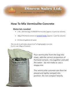
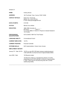


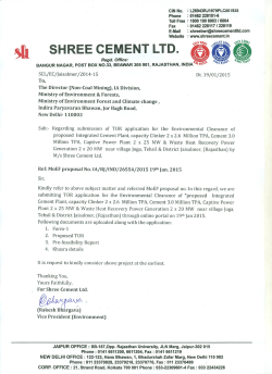

© Copyright 2026