
Brazilian atlas of CO2 capture and geological storage
Brazilian Atlas of CO2
Capture and Geological Storage
Center of Excellence in Research and Innovation in
Petroleum, Mineral Resources and Carbon Storage
Chancellor
Dom Jaime Spengler
President
Joaquim Clotet
Vice- President
Evilázio Teixeira
Editorial Board
Jorge Luis Nicolas Audy | President
Jorge Campos da Costa | Editor in chief
Jeronimo Carlos Santos Braga | Director
Agemir Bavaresco
Ana Maria Mello
Augusto Buchweitz
Augusto Mussi
Bettina Steren dos Santos
Carlos Gerbase
Carlos Graeff Teixeira
Clarice Beatriz da Costa Sohngen
Cláudio Luís C. Frankenberg
Érico João Hammes
Gilberto Keller de Andrade
Lauro Kopper Filho
Brazilian Atlas of CO2
Capture and Geological Storage
Center of Excellence in Research and Innovation in
Petroleum, Mineral Resources and Carbon Storage
October/2014
© 2014, CEPAC/EDIPUCRS
Published in April 2015
organizers
João Marcelo Medina Ketzer
Claudia Xavier Machado
Cover design Shaiani Duarte
Gabriela Camboim Rockett
Layout design Dani Editorial
Rodrigo Sebastian Iglesias
Final editing Neil Wildgust, Meade Goodwin and Diane Teigiser
Contributors
Anderson José Maraschin
Caroline Inda Centeno
Carolina Lacerda Macalos
Clarissa Lovato Melo
Center of Excellence in Research and
Innovation in Petroleum, Mineral
Resources and Carbon Storage
Eleani Maria da Costa
Felipe Dalla Vecchia
Gesiane Fraga Sbrissa
Giancarlo Caporale
Jeane Estela de Lima Dullius
João Miguel Faim Martins
Jorge Alberto Villwock (in memoriam)
Lia Weigert Bressan
Luciana Probst de Castro
Luiz Henrique Souza da Rocha
EDIPUCRS – Editora Universitária da PUCRS
Marta Kerber Schütz
Av. Ipiranga, 6681 – Prédio 33
Caixa Postal 1429 – CEP 90619-900
Porto Alegre – RS – Brasil
Phone/fax: (51) 3320 3711
E-mail: [email protected] – www.pucrs.br/edipucrs
Martimiano Krusciel de Moraes
Rafael Valdetaro Bianchini
Roberto Heemann
Rosane Angelica Ligabue
International Data Cataloguing in Publication (CIP)
B827
Brazilian atlas of CO2 capture and geological storage [recurso
eletrônico] / org. João Marcelo Medina Ketzer ... [et al.]. –
Dados eletrônicos. – Porto Alegre : EDIPUCRS, 2014.
66 p.
Sistema requerido: Adobe Acrobat Reader
Modo de acesso: <http:www.pucrs.br/edipucrs>
ISBN 978-85-397-0577-1
1. Engenharia. 2. Captura de Carbono – Atlas.
3. Carbono – Armazenamento – Atlas. I. Ketzer, João
Marcelo Medina.
CDD 665.89
Cataloguing prepared by the Department of Information Processing – PUCRS Central Library.
ALL RIGHTS RESERVED No part of this book may be reproduced in any form or by any means or process, especially
printing, microfilming, photographic, phonographic, videographic systems. Also prohibited are memorization
and/or partial or total recuperation, as well as the inclusion of any part of this book in any data processing
system. These prohibitions refer to graphic and editing characteristics of this book. Any violation of copy rights
is considered a crime (Article 184 and inclusive items of the Penal Code), subject to imprisonment and fines,
retrieval of the material and indemnification (Arts. 101 to 110 of Law 9.610, of 19.02.1998, Copyright Law).
Sandra Mara Oliveira Einloft
Viviane Romeiro
Wagner dos Santos Oliveira
acknowledgements
Agência Nacional de Energia Elétrica (ANEEL)
Agência Nacional do Petróleo, Gás Natural e
Biocombustíveis (ANP)
Carbon Sequestration Leadership Forum (CSLF)
Conselho Nacional de Desenvolvimento Científico e
Tecnológico (CNPq)
Global CCS Institute (GCCSI)
Instituto Brasileiro de Geografia e Estatística (IBGE)
International Energy Agency (IEA)
John Bradshaw
Ministério de Ciência, Tecnologia e Inovação (MCTI)
Ministério dos Transportes (MT)
Paulo Cunha
Paulo Rocha
PETROBRAS Petróleo Brasileiro S.A.
DISCLAIMER
This publication was made possible through funding from the Global CCS Institute, in the interest of broadening
the discussion on CCS as a key climate change mitigation option. The views contained in this publication do not
necessarily represent those of the Global CCS Institute or its Members. The Global CCS Institute does not give any
representation or warranty as to the reliability, accuracy or completeness of the information contained in this publication and, to the maximum extent permitted by law, does not accept any liability arising in any way (including by
negligence) for any use or reliance on the information contained in this publication.
Table of contents
Foreword | 7
Center of Excellence in Research and Innovation in
Petroleum, Mineral Resources and Carbon Storage | 9
CO2 Storage Research | 10
Unconventional Energy Sources Research | 11
Carbon Capture and Storage (CCS) Technology
Overview | 13
CO2 Capture and Separation | 14
CO2 Transport | 16
CO2 Geological Storage | 16
Brazilian Context | 27
CO2 Stationary Sources | 28
CO2 Capture | 31
Transport of CO2 | 33
CO2 Storage | 38
Prospectivity for CO2 Geological Storage in Brazil | 55
Low prospectivity | 57
Medium prospectivity | 58
High Prospectivity | 59
Final Remarks | 61
References | 63
Foreword
The Center of Excellence in Research and Innovation in Petroleum, Mineral Resources and Carbon
Storage (CEPAC) and the Pontifical Catholic University of Rio Grande do Sul (PUCRS) are proud to present the first Brazilian Atlas of CO2 Capture and Geological Storage. This Atlas represents the outcome
of a large research effort by CEPAC since its foundation, in 2007, dedicated to comprehension, development, and dissemination of the technologies involved in the CO2 capture and storage (CCS) in Brazil, a
recognized solution for the reduction of greenhouse gas emissions worldwide.
For the development of CCS technologies, an international effort in the mapping of CO2 sources
and evaluation of potential target reservoirs for geological storage is necessary, and the release of this
Atlas positions Brazil among the countries that are on the way to accomplish this task.
CEPAC and PUCRS firmly believe that the publication of this Atlas will represent a substantial
step in the development of CCS in Brazil and the dissemination of knowledge of these technologies,
contributing to actions leading to mitigation of climate change.
The Organizers
The Global CCS Institute (the Institute) is pleased to sponsor the Brazilian CO2 Storage Atlas. The
Atlas is a welcome addition to the growing body of knowledge advancing carbon capture and storage
(CCS) globally and particularly in Latin America. Identifying viable geologic storage sites is an essential
part of CCS deployment and one that can take several years. The completion of Brazil’s Atlas represents
a significant step forward.
The Institute acknowledges and commends the major contribution made by the Centre of
Excellence in Research and Innovation in Petroleum, Mineral Resources and Carbon Storage (CEPAC)
to produce this work. We look forward to an ongoing collaborative relationship with CEPAC and other
Brazilian stakeholders to progress CCS knowledge and expertise. We also thank the many other colleagues who provided technical and logistical support to produce the Atlas and who provided reviews.
The Atlas is an important milestone in the Institute’s collaboration with CEPAC and other Brazilian
stakeholders who are dedicated to progressing CCS knowledge.
The Global CCS Institute accelerates CCS, a vital technology to tackle climate change and provide
energy security. We advocate for CCS as one of the options required to reduce greenhouse gas emissions from power generation and industrial sources.
The Institute shares information from our international membership while building capacity and
bringing together projects, policymakers and researchers to overcome challenges and ensure that CCS
can become a widely-used technology as quickly as possible. We collaborate with international organizations involved in advancing CCS, driving progress by integrating expertise with government decision
making and international policy agreements.
Elizabeth Burton
Global CCS Institute, General Manager Americas
Center of Excellence in Research and
Innovation in Petroleum, Mineral
Resources and Carbon Storage
Headquartered in the Central Campus of the Pontifical Catholic University of Rio Grande do Sul (PUCRS),
the Center of Excellence in Research and Innovation in Petroleum, Mineral Resources and Carbon Storage
(CEPAC) is the result of a joint initiative of PETROBRAS and PUCRS, through the University’s Environment and
Natural Resources Institute. CEPAC is an interdisciplinary center dedicated to research, development, innovation, demonstration and technology transfer in carbon dioxide (CO2) storage and unconventional sources of
energy related to fossil fuels such as gas hydrates, shale gas, methane in coal seams and hydrogen. Through this
research CEPAC aims to contribute toward the mitigation of climate change and production of cleaner energy
sources (Figure 1).
Figure 1: CEPAC facilities.
Source: CEPAC.
10
Center of Excellence in Research and Innovation in Petroleum, Mineral Resources and Carbon Storage
CO2 Storage Research
When its activities started in 2007, CEPAC became the first Brazilian research center dedicated exclusively to research on CO2 storage. Among the projects and research areas developed, are
the following:
•• Geological and mineralogical characterization of storage reservoirs and reservoir interaction with CO2
•• Investigation of the integrity and reliability of different materials and procedures applied to
the injection of CO2 through injection wells, in order to maximize the safety and feasibility of
geological carbon storage.
•• Studies of the geochemical interactions and flow mechanisms in the CO2-water-rock system
with focus on Brazil’s pre-salt reservoirs.
•• Development of a Geographic Information System (GIS) containing data on CO2 emissions resulting from stationary sources, transport infrastructure, and potential geological reservoirs.
Figure 2: Numerical model showing displacement of CO2 in a reservation over time.
Source: CEPAC.
Figure 3: Stainless steel vessels used in laboratory experiments for simulation of reservoir conditions (left).
Configuration of an experiment to evaluate CO2-cement interaction (right).
Source: CEPAC.
Brazilian Atlas of CO2 Capture and Geological Storage
Center of Excellence in Research and Innovation in Petroleum, Mineral Resources and Carbon Storage
Unconventional energy sources research
Ongoing projects focused on the development of knowledge and technology for unconventional
energy sources include:
•• Evaluation of the potential for enhanced coal bed methane recovery through implementation of a
pilot project for methane production tests in Porto Batista, Rio Grande do Sul. These tests included perforation of two wells for production of methane, injection and monitoring of CO2 (Figure 4).
•• Stratigraphic characterization, petrophysics, petrography, geochemistry, adsorption/desorption of gases involved in hydraulic fracturing and selection of potential areas for exploration of shale gas.
•• Study of the origin and geological evolution of the Rio Grande Cone (Pelotas Basin), focusing
on gas hydrate deposits (Figure 5).
Figure 4: Pilot project for coal bed methane potential evaluation (Porto Batista/RS, Brazil)
Source: CEPAC.
Figure 5: Oceanographic mission in the Southern Atlantic for research on gas hydrates
Source: CEPAC.
11
Carbon Capture and Storage (CCS)
Technology Overview
The steep increase in atmospheric concentration of CO2 and other greenhouse gases during the
past two centuries has been widely recognized as the cause of global temperature rises of at least 0.8°C
in the same period. Considering the current trend in the world’s economic and population growth, this
concentration will continue to rise. This could potentially lead to a further increase in temperature and
severe climatic change. Therefore, reducing emissions of CO2 and controlling its atmospheric concentration are challenges that need to be addressed.
One of several existing measures for reducing greenhouse gas emissions to mitigate climate
change is the capture and storage of carbon dioxide in geological reservoirs (CCS)(Figure 6). This technology consists in the integrated process of the capture and separation of CO2 from stationary sources
(industries, power plants, etc.), transport to an adequate storage site, and injection into the porous
space of deep underground rock formations.
CCS is one of the most important technologies available to reduce CO2 emissions. CCS stands
out due to its enormous potential in terms of CO2 volumes that can be stored in geological media for
millions of years.
Figure 6: Carbon capture and geological storage.
Source: Bellona.
14
Carbon Capture and Storage (CCS) Technology Overview
CO2 capture and geological storage includes four basic stages:
•• CO2 capture and separation from other gases from the stationary emitting source, to achieve
a high purity stream (typically greater than 90%);
•• CO2 transportation from emitting source to the storage location, which can be done through
pipelines, trucks or tankers;
•• CO2 storage in different geological formations, each with specific advantages and disadvantages, and
•• CO2 measurement, monitoring and verification during and after injection phase into a geological formation.
There are different technologies available for each stage, however the feasibility and performance of each technology can vary according to the specific characteristics of the project.
CO2 Capture and Separation
CO2 capture can be carried out through four main processes: post-combustion, pre-combustion,
oxy-combustion and industrial processes separation (Figure 7).
Figure 7: Overview of CO2 capture processes.
Source: IPCC.
Brazilian Atlas of CO2 Capture and Geological Storage
Center of Excellence in Research and Innovation in Petroleum, Mineral Resources and Carbon Storage
During post-combustion capture the
CO2 is separated from the flue gas after
burning fossil fuels or biomass in the presence of air (oxygen and nitrogen). The main
products of this combustion are nitrogen
(N2) and carbon dioxide (CO2), in which the
latter is in low concentration (3-15% vol.).
Currently, post-combustion processes are
among the most used in CO2 capture from
stationary sources (Figure 8).
Pre-combustion capture is a threestage process. First, the fuel (coal or biomass) is gasified, i.e., converted to hydrogen (H2) and carbon monoxide (CO),
a mixture called syngas. Next, a steam
reforming (shift reaction) converts CO in
CO2, to yield more hydrogen. After these
processes, the CO2 must be separated from
the hydrogen. The latter can then be used
in several applications such as fuels or energy generation.
Figure 8: Post-combustion CO2 capture plant
Source: GCCSI.
In the oxygen combustion technology (or oxy-combustion), the fuel is burnt
with pure oxygen. In this way, CO2 (in high
concentration, > 80%) and water vapor are
produced, which can be easily separated by
condensation. A critical part of this technology is the previous requirement for oxygen
separation from air, which is usually carried
out through a cryogenic process (an energy-intensive technique) (Figure 9).
Figure 9: Air separation unit.
Source: Wikipedia.
Several types of industrial processes may be important large-scale sources of CO2. In industries
such as steel, cement and fertilizer plants, and natural gas processing, significant amounts of CO2 may
be produced and captured through different methods.
Depending on the capture process, a technology is necessary to separate CO2 from other gases.
Several methods may be used in this stage. The most common ones are based on selective absorption of
CO2 (chemical or physical), using solvents such as amines. Solid adsorption with membranes or zeolites
15
16
Carbon Capture and Storage (CCS) Technology Overview
is also employed. Other technologies are being investigated to optimize this separation step, such as
ionic liquids - room temperature liquid salts with a highly selective CO2 dissolution capacity.
CO2 Transport
Captured CO2 must be transported from the emitting source to the storage site. The pipeline system, similar to those used to transport natural gas, is a frequently utilized CO2 transport option. Other
options for transport include trucking and shipping.
Figure 10: CO2 transport options.
Source: GCCSI.
Usually CO2 is compressed to a supercritical state (or a ‘dense phase’) for transport and injection.
Depending on how long the pipeline is, the CO2 may need to be ‘recompressed’ along various points of
the pipeline to keep it in this ‘dense phase’ (Figure 10).
There are still some technological challenges associated with pipeline transport of CO2. Several
factors need to be considered in long-distance pipeline projects, such as terrain characteristics, moisture content of the gas, accidental entry of wet gas into the pipeline and corrosion resistance of the
pipeline material.
CO2 Geological Storage
The main geological options than can safely store large amounts of CO2 and keep it from reaching
the atmosphere are oil and gas fields and deep saline formations:
Brazilian Atlas of CO2 Capture and Geological Storage
Center of Excellence in Research and Innovation in Petroleum, Mineral Resources and Carbon Storage
Figure 11: CO2 geological storage options.
Source: CEPAC.
In most cases, and due to the increase in temperature and pressure with depth, injected CO2 will
be in a supercritical (or dense phase) state (pressure > 7.38 megapascal (MPa) and temperature > 31.1° C).
In this condition, CO2 acquires a liquid-like density, between 600 and 800 kilogram per cubic meter (kg/
m3) therefore occupying a smaller pore volume, leading to more efficient storage (Figure 12). To ensure
storage in a supercritical state, the minimum depth estimated for a reservoir is around 800 meters (m).
Figure 12: CO2 density and state changes with depth.
Source: CO2CRC.
17
18
Carbon Capture and Storage (CCS) Technology Overview
A reservoir rock is usually well suited for CO2 storage according to the following properties:
•• Porosity: refers to the volume of fluid that can be contained within the rock between the rock
‘pore spaces’, i.e. the minute spaces existing between rock grains. Porosity often decreased
with depth, due to rock compaction and cementation, i.e. these ‘pore spaces’ become even
smaller, so less fluid can be stored there (Figure 13).
Figure 13: Rock porosity (in blue).
Source: CO2CRC/CEPAC.
•• Permeability: refers to the connectivity between the rock pore spaces, i.e. the space or channels linking the pore spaces that fluid can flow through, from one pore space to the next. A
minimum permeability is necessary and especially important in the early stages of a storage
project to avoid CO2 injectivity issues (Figure 14).
Figure 14: Permeability (flow paths).
Source: CO2CRC/CEPAC.
Physical and chemical trapping mechanisms are responsible for preventing the injected CO2
from migrating back to the surface (Figure 15). A requirement for a physical trapping mechanism is
the existence of an impermeable cap-rock formation, overlying the storage reservoir. This cap-rock
acts as an obstacle and stops the vertical migration of the CO2 to the upper parts of the sedimentary basin and the atmosphere (Figure 16).
Brazilian Atlas of CO2 Capture and Geological Storage
Center of Excellence in Research and Innovation in Petroleum, Mineral Resources and Carbon Storage
Figure 15: Typical geological reservoir and caprock setting.
Source: GCCSI.
Figure 16: CO2 trapping mechanisms in geological reservoirs.
Source: CEPAC.
Physical trapping of fluids (like CO2 in its dense phase) in the sub-surface is achieved by means of a
caprock and ‘traps’, which can be structural or stratigraphic (or even a combination of both).
CO2 injected into storage reservoirs, especially deep saline formations, will over time partially dissolve into the saline groundwater (brine) present in these reservoirs. The rate at which this dissolution
occurs will vary according to a number of factors, including reservoir geology, pressure and temperature
conditions, and brine composition. This mechanism is referred to as ionic or solubility trapping and can
serve as a further means to immobilize CO2 in the reservoir and reduce risks associated with any potential
leakage. In the ionic or solubility trapping mechanism, CO2 dissolved in the aqueous phase of the geologic
formation is retained as dissolved carbonate and bicarbonate (CO32- and HCO3-, respectively) species.
19
20
Carbon Capture and Storage (CCS) Technology Overview
Dissolved CO2 may also chemically react with reservoir rocks and fluids, causing precipitation
of carbonates. This process is referred to as mineral trapping, and has the potential to immobilize
injected CO2 in a solid phase. Mineral trapping occurs when the dissolved CO2 reacts with selected
cations (such as Ca2+ or Mg2+), present in the aqueous phase or originated from mineral dissolution.
Once in a solid phase, CO2 will likely remain immobilized for thousands or millions of years, and therefore is considered the safest trapping mechanism.
Adsorption trapping occurs in coal seams, where the CO2 displaces the methane contained in the
seam, and then remains adsorbed in the coal matrix.
Storage in oil and gas fields
Injection of CO2 can be carried out in particularly, but not exclusively, in mature or depleted oil
and gas fields. Mature oil fields are those where hydrocarbon production is in its final stages, while
depleted fields are those where only residual oil (trapped in the pores of the reservoir rock) remains.
This operation can increase production of hydrocarbons from these fields, resulting in economic benefits. Furthermore, these projects take advantage of the geological data acquired in their exploration
and development.
For several decades, CO2 has been used as injection fluid for additional recovery of oil and gas.
In over 100 projects worldwide, injected CO2 has been used to successfully recover additional oil,
given that significant reserves can remain in reservoirs after conventional recovery. This technique is
known as Enhanced Oil Recovery (EOR) (Figure 17). Most of these projects are located in the United
States, and a large proportion of the CO2 used has been obtained from natural accumulations, with a
smaller part coming from anthropogenic sources. Brazil has EOR projects developed in the Recôncavo
Basin, which will be discussed further on in this Atlas.
Figure 17: CO2 Enhanced Oil Recovery
Brazilian Atlas of CO2 Capture and Geological Storage
Center of Excellence in Research and Innovation in Petroleum, Mineral Resources and Carbon Storage
CO2-EOR operations have the potential to extend the economic life of individual fields by a
decade or more, as proven by a number of projects where several tens of percent of additional oil
reserves have been produced. Typically, a proportion of the injected CO2 is stored in the reservoir by
trapping mechanisms as described above, whilst some injected CO2 is produced from the reservoir
with oil. The proportion of this ‘recycled’ CO2 increases with time, and it should be stripped from the
oil and re-injected into the reservoir with ‘new’ CO2 in a closed loop system.
The ultimate storage capacity provided by any CO2-EOR project will depend on a number of
technical and economic factors. At the end of economic oil production, an operator may choose to
use the closed loop system to ensure all CO2 is stored in the reservoir before sealing and abandoning
wells. Alternatively, a significant portion of the CO2 could be produced for further utilization in other
oil fields. Storage capacity could be increased with injection into residual oil zones beneath the main
field, or into the reservoir for storage only.
Storage in Deep Saline Formations
Deep Saline Formations (DSF) are rock formations with pore spaces filled with highly saline
(salty) groundwater, also commonly referred to as brine. An arbitrary limit of 10,000 milligrams per
litre (mg/l) of dissolved solids is usually considered the lower limit of salinity of DSF suitable for
CO2 geological storage. For comparison, potable water in Brazil has a maximum limit of 500mg/l,
whereas seawater has an average salinity of 34,600mg/l. In some DSF, brine salinity can reach up to
300,000mg/l. These considerations of salinity are less relevant in offshore storage scenarios, where
groundwater is unlikely to be utilized (Figure 18).
Figure 18: Water salinity grades
Deep saline aquifers are more common than oil and gas fields and coal deposits, and have an
enormous potential for CO2 storage in terms of capacity. However, there tends to be much less information available on these reservoirs, compared to the data available on hydrocarbon reservoirs and
coal deposits.
21
22
Carbon Capture and Storage (CCS) Technology Overview
Large-scale commercial projects
Currently, there are 12 large-scale projects (i.e. injecting more than 400 ktonnes/year)
where CO2 is stored in geological reservoirs. In total, these projects store more than 20
million tonnes of CO2 in geological formations each year. The operational projects that
have storage in deep saline aquifers are all associated with CO2 captured from produced
natural gas, such as the case of the Sleipner Project in the North Sea, and the Snøhvit, in
the Barents Sea, both operated by the Norwegian oil company StatoilHydro. In Sleipner,
the natural gas produced has a CO2 content of approximately 9%, which is separated,
purified and injected in the Utsira Formation, 800 m below the sea bed of the North Sea,
at a rate of 1Mt/year. In the Snøhvit field, CO2 is also separated from natural gas (ca.
5-8% content), and injected 2300 m below the sea bed in the Stø formation.
Coal is a combustible sedimentary rock with high carbon content, formed by decomposition and
alteration of organic matter from vegetable sources (Figure 19).
Figure 19: Coal sample.
Source: CEPAC.
Coal beds have a natural affinity for adsorbing CO2 in its microporus matrix. Coal can trap approximately twice as much CO2 as methane, which is commonly found trapped in the coal beds for
millions of years. Methane in coal beds is exploited as an energy resource in countries such as Australia,
China and the U.S. This activity is termed Coal-bed Methane recovery (CBM). Currently, there are several projects for CBM exploitation worldwide. In the U.S., approximately 10% of the domestic natural gas
is originated from CBM projects.
Due to the difference in coal’s adsorption capacity between carbon dioxide and methane, CO2
molecules are adsorbed while CH4 molecules are released, in a process called enhanced coal-bed meth-
Brazilian Atlas of CO2 Capture and Geological Storage
Center of Excellence in Research and Innovation in Petroleum, Mineral Resources and Carbon Storage
ane recovery (ECBM). Once injected, CO2 will be adsorbed preferentially in the coal matrix, displacing
the methane to the coal’s fracture system, which can be produced as a free gas. The depth window for
storing CO2 in coals is between 300 and 900 meters.
According to global estimates, storage capacity associated with coal is between 15 to 200 billion
tonnes of CO2.
Other reservoir options
Coal beds have also been considered as a potential reservoir for CO2 storage although they
have yet to be demonstrated to be an effective and secure option. CO2 storage in mafic rocks (i.e. rocks
rich in iron and magnesium minerals) has also been investigated in several studies. Storage in mafic
rocks is of interest due to the considerable volume and distribution of these rocks. The composition of
these rocks, rich in magnesium, iron and calcium, could facilitate chemical reactions with CO2, potentially leading to mineral trapping. Studies investigating the possibility of CO2 injection in volcanic rocks
are ongoing in India and the U.S. However, storage in these rock types still needs to be validated with
pilot projects.
Site selection criteria
Potential geological reservoirs for CO2 storage must meet certain requirements that ensure the
integrity of the storage site and the efficiency of the activity, such as:
•• Adequate capacity and adequate injectivity rates (permeability in the vicinity of injection wells);
•• Cap-rock containment capacity for preventing upward migration of CO2;
•• Stable geological environment (geochemically and geomechanically).
The implementation of a storage project will depend upon a combination of favorable factors,
which includes:
•• Basin characteristics (adequate stratigraphy and reservoir depth, favorable geothermal and
hydrodynamic regimes, low seismic activity);
•• Basin resources (occurrence of oil and gas for EOR, coal for ECBM, safe distance from freshwater aquifers, availability of deep saline formations);
•• Oil industry maturity and infrastructure (existing rigs, pipelines, wells and geological data);
•• Social and economic issues (appropriate development levels, funding opportunity, public
acceptance).
Safety of geological storage
Storage safety is an essential consideration for CCS projects. Although CO2 is a non-combustible
low-toxicity gas, in high concentrations it can be dangerous to human health and the environment.
Therefore, safety and risk assessments are always necessary to evaluate potential sources of CO2 leakages or seepages away from the storage complex, in order to plan remediation options.
Experience with natural gas and CO2 reservoirs, and the oil and gas industry expertise in transporting and injecting carbon dioxide in geological reservoirs provide good examples where the transport
and storage of CO2 has already been demonstrated.
23
24
Carbon Capture and Storage (CCS) Technology Overview
The safety of subsurface storage can be supported by the several known natural accumulations of
CO2, and can be used to gather further knowledge on containment conditions. These natural fields range
from shallow (100’s meters) to deep (up to 5 km) reservoirs, with high-purity (> 90%) CO2 accumulations
around the world that can be used as analogs for the study of geological storage long-term effects.
Monitoring, measuring and verification of CO2
CO2 is likely to remain stored for millions of years, however, in any given project, the safety
of storage must be ensured by monitoring the CO2 in the subsurface. Atmospheric, soil and shallow
groundwater monitoring is also essential to ensure that in the unlikely event of any leakage to the shallow subsurface or above surface, any associated impacts could be rapidly mitigated.
Monitoring operations must be carried out before, during and after the injection phase (always
in comparison to baseline measurements), and usually rely on proven technologies employed in the oil
and gas industry. Geophysical methods are predominantly used, such as seismics and electric resistivity.
Geochemical methods can also be used to evaluate the movement of CO2 in the subsurface through fluid analyses (Figure 20). Some of these tools can be used to understand or characterize the local geology
before injection, and models can be made to predict the behavior of the injected CO2. Rigorous characterization is needed to select appropriate storage sites with adequate capacity, injectivity and containment, and to design safe operational parameters, for example maximum injection rates. Thorough
characterization is also required to inform a comprehensive risk assessment process, to demonstrate
that the probability of any potential leakage event is very low and that any associated impacts could be
identified, monitored and mitigated appropriately. It is usually considered that a leakage of 1% of stored
CO2 in a hundred years would be an acceptable value.
Figure 20: CO2 Monitoring Techniques.
Source: CO2 Capture Project.
Flow of injected CO2 in the sub-surface can be modelled prior to injection by simulating CO2
interactions with the reservoir and cap-rock in laboratory experiments. These experiments simulate
the subsurface conditions using real rock and fluid samples. Simulations can also be carried out using
Brazilian Atlas of CO2 Capture and Geological Storage
Center of Excellence in Research and Innovation in Petroleum, Mineral Resources and Carbon Storage
numerical modeling tools to predict flow and chemical interactions in the storage site in geological
timescales. The observed flow of the injected gas in the subsurface can be compared with the predicted
paths, allowing calibration of both experimental and numerical models.
Monitoring of shallow or surface environmental compartments also needs to be undertaken
prior to injection to provide baseline data, and during/after injection to detect any changes or impacts that might arise in the unlikely event of leakage. These compartments include: (1) freshwater
aquifers and groundwater resources; (2) the shallow subsurface including the soil profile; (3) surface water bodies; and (4) the atmosphere. A variety of methods can be employed for shallow and
surface environmental monitoring, such as chemical and biological analyses, tracers and remote
sensing, among others.
CO2 Monitoring Field Laboratory
In December 2011, the Ressacada project, the first Brazilian CO2 monitoring, measuring
and verification (MMV) field lab was initiated, as a joint R&D project between PETROBRAS
and academic institutions focus on testing and validation of CO2 monitoring techniques
and methodologies. Field experiments consist of CO2 injection and controlled releases
over a specified time to simulate shallow subsurface leakages reaching both saturated and
unsaturated sediments and soil, and ultimately the atmosphere. Time-lapse monitoring
was carried out following the releases, focusing the investigation on several areas such as
atmospheric fluxes and concentration, groundwater studies, CO2 tracer studies, geophysical
surveys (electrical imaging techniques), soil CO2 flux measurements and evaluation of botanic
stress using remote sensing.
The experimental area is located in the Ressacada Farm, a rural region close to the city of
Florianópolis, Southern Brazil. Two injection campaigns were conducted in the site, both using
vertical wells for CO2 injection.
Hence, monitoring, measuring and verification of CO2 in CCS projects is not limited to the geological reservoir target of injection, or the confining cap-rock. it must consider all the areas where CO2 can
migrate, including soil, water bodies and atmosphere.
CO2 storage capacity
The maximum theoretical CO2 storage capacity in any rock formation can be estimated as a function of effective porosity (i.e the amount of connected pore spaces in the rock) and the volume of the
formation. The capacity for storing CO2 depends ultimately on the effective porosity (i.e. how much pore
space is available) and volume of the reservoir rock. Also, capacity estimation at both regional and local
scales depends on a number of other factors including geological structure, fluid flow characteristics
injection rates, reservoir conditions, etc.
According to the concept of the techno-economic resource-reserve pyramid proposed by the
Carbon Sequestration Leadership Forum (CSLF) for CO2 storage capacity estimation methodology, four
different types of capacities can be estimated, as outlined below.
25
26
Carbon Capture and Storage (CCS) Technology Overview
Theoretical capacity: represents the physical-geological limit for fluid storage, assuming that
CO2 will ocupy all porous space of the reservoir.
Effective storage capacity will be smaller than the theoretical capacity, and is obtained by applying a number of technical parameters (geological or engineering), which will limit the capacity that
can be utilized.
Practical capacity will be smaller than the effective capacity, and can be calculated by considering technical, legal and regulatory barriers, infrastructure, and economic issues.
Source-sink matched capacity: corresponds to a fraction of the practical capacity that is associated with CO2 sources that can be captured, obtained by matching those sources against mapped
storage formations with practical capacity estimates.
In oil and gas fields, through specific analyses of each reservoir, the storage capacity of carbon
dioxide can be estimated from reserves and production databases. In hydrocarbon reservoirs under
production or already depleted, the injected CO2 may occupy the pore volume previously occupied by
the hydrocarbons.
Estimating storage capacity for DSF may be challenging, due to the often limited amount of
pre-existing characterization data and corresponding uncertainties over local and regional pressure and
fluid flow conditions (hydrodynamics) that can influence injectivity and capacity. Moreover, the possible absence of trapped, buoyant fluids such as hydrocarbons require characterization efforts for DSF to
demonstrate the presence of suitable sealing or cap-rock layer(s) above the intended reservoir. These
factors may require greater investments of time and money to prove geological storage sites in DSF.
Brazilian Context
Brazil has an overall favorable situation regarding the potential for CO2 geological storage.
The country has a large area covered with sedimentary basins, both onshore and offshore. Most
of the stationary emitting sources, especially in the Southeast region, are located in proximity to
these basins (Figure 21).
Fontes emissoras de CO2/CO2 emitting sources
Bacia sedimentar/Sedimentary basin
Figure 21: Sedimentary basins and CO2 emitting sources in Brazil.
28
Brazilian Context
CO2 Stationary Sources
Source: João Marcelo Ketzer.
The large CO2-emitting stationary sources in Brazil are those related to power plant, biomass,
cement, steel, oil refining, ethanol, ethylene and ammonia sectors and the majority are concentrated in
the country’s Southeast region. That is especially the case for biomass and ethanol, for example, which
are concentrated in the Southeast and Central regions. In total, all sources are responsible for the emission of 395 MtCO2/year (in 2006). The energy generation sector is distributed all over the national territory, with some concentration in the Southeast, Northeast and North. Cement plants occur in smaller
numbers and are dispersed throughout the country (Figure 22; Figure 23).
In addition to onshore stationary sources, Brazil has several offshore sources – mostly petroleum
platforms. Despite their significant emissions, the location of these facilities are not available from official records, therefore are not represented in this Atlas.
Data for emitting sources was obtained from the National Electric Energy Agency (for power
plants) and the International Energy Agency.
Figure 22: CO2 stationary sources per type.
Brazilian Atlas of CO2 Capture and Geological Storage
Center of Excellence in Research and Innovation in Petroleum, Mineral Resources and Carbon Storage
Figure 23: CO2 stationary sources per type: Southeast region.
Energy generation is the largest source of CO2 emissions, with over 1100 facilities in operation
(Figure 24). This sector is responsible for 43.6% of Brazil’s CO2 emissions from stationary sources and
produces over 170,000 kilotones (kt) of carbon dioxide per year (Figure 25). Following power generation,
the second largest emitter is biomass, which emits approximately 136Mt of CO2 annually through more
than 568 plants. Cement, steel and refining facilities also stand out for the amount of emitted CO2, together accounting for 18% of Brazilian emissions, or a total of 71.5Mt per year.
Figure 24: CO2 stationary sources per sector
Figure 25: CO2 emissions per industry
29
30
Brazilian Context
It should be noted that,
for energy facilities where CO2
emission data was not available, the estimation was based
on the assumption that the
facilities operate 152 days per
year, 24 hours a day, at maximum efficiency. For each type
of industry, a CO2 emission factor was applied based on the
nature of the fuel used for energy generation.
Emissões de CO2 (Kt/ano)
CO2 emissions (Kt/year)
<200
201 - 750
751 - 1800
1801 - 3800
3801 - 6400
The most emission intensive geographical areas are
located in the central-southeast
portion of the country, with
some clusters in the coastal areas, where many state capitals
and industrial cities are located
(Figure 26; Figure 27).
Figure 26: CO2 emissions from stationary sources per mass emitted annually.
Emissões de CO2 (Kt/ano)
CO2 emissions (Kt/year)
<200
201 - 750
751 - 1800
1801 - 3800
3801 - 6400
Regiões/Regions
Norte/North
Nordeste/North East
Centro-Oeste/West Central
Sudeste/South East
Sul/South
Figure 27: CO2 emissions from stationary sources per mass emitted annually: Southeast region.
Brazilian Atlas of CO2 Capture and Geological Storage
Center of Excellence in Research and Innovation in Petroleum, Mineral Resources and Carbon Storage
CO2 Capture
Based on the fuel
source for energy generation
in Brazilian energy and industrial facilities, the most likely CO2 capture process to be
used in each source was assigned. It should be noted that
the suggested process is not
based on an analysis undertaken for each specific plant,
but was based on existing literature regarding maturity of technology and its usual application in different industrial/energy sectors. From this information, a map was generated with the potential capture method for each source.
In this map, only CO2 sources with emissions over 0.1 Mt/year were considered. When more than one
process is possible, the most viable (economically and technologically) was considered (Figure 28;
Figure 29). It was concluded that the process most likely to be applied, associated with the existing
sources, would be post-combustion. This process could potentially be applied on 78% of the sources,
capturing over 243 Mt/year. In many sources (ca. 9%), CO2 is produced in a nearly pure stream (such
as the case of ethanol production plants); therefore simple separation processes such as dehydration
of the steam are applicable (Figure 30).
Figure 28: Potential CO2 capture processes for emitting sources in Brazil.
31
32
Brazilian Context
Figure 29: Potential CO2 capture processes: Southeast region
Figure 30: Potential amount of CO2 captured by capture process.
Brazilian Atlas of CO2 Capture and Geological Storage
Center of Excellence in Research and Innovation in Petroleum, Mineral Resources and Carbon Storage
Case study: CO2 capture test facility in Brazil
In São Mateus do Sul, in the Paraná State, a series of tests were carried out between
2011 and 2012 to evaluate oxy-combustion technology in a fluid catalytic cracking
(FCC) unit, as part of the international CO2 Capture Project (CCP)*.
FCC units convert low-value, heavy hydrocarbons into a lighter, more valuable
product. A catalyst, which decomposes over time, is necessary for this conversion,
and a recovery process using air is used to regenerate the catalyst. Using oxycombustion technology, where air is replaced by pure oxygen, a high-purity CO2
stream is obtained as the combustion product. Results of the investigation confirmed
the technical and economical viability of upgrading an FCC unit focusing on CO2
capture through oxy-combustion (Figure 31).
Figure 31: Oxy-combustion.
More information at:
Leonardo F. de Mello, Rodrigo Gobbo, Gustavo T. Moure, Ivano Miracca, Oxycombustion
Technology Development for Fluid Catalytic Crackers (FCC) – Large Pilot Scale
Demonstration, Energy Procedia, Volume 37, 2013, Pages 7815-7824.
* The CO2 Capture Project is a partnership, signed in 2000, between the energy companies BP, Chevron, Eni, PETROBRAS, Shell and Suncor, with the involvement of government entities from the U.S., European Union and Norway.
Transport of CO2
In Brazil, transport of fluids in the petroleum industry is done mostly using pipelines and tankers. Pipelines have several advantages over other transportation options, such as the capacity to move
substances in high volumes, across difficult terrains, often with low unit costs.
33
34
Brazilian Context
However, the pipeline share of the Brazilian transport matrix is low - approximately 4.2%.
Highways and railroads are the main transport options used in Brazil nowadays (Figure 32).
The Brazilian pipeline infrastructure is concentrated mostly in the southeast and coastal regions
of the country, as most of the oilfields exploited are located in offshore basins (Figure 33).
Figure 32: Cargo transportation matrix.
Source: Ministério dos Transportes, 2011.
Figure 33: Pipeline network and terminals.
Brazilian Atlas of CO2 Capture and Geological Storage
Center of Excellence in Research and Innovation in Petroleum, Mineral Resources and Carbon Storage
Brazil currently has an infrastructure
of nearly 15,400 kilometers (km) of pipelines,
part of which could potentially be used for
CO2 transport. The same route could be used
for CO2 pipelines, thereby minimizing land-use
and ownership issues. Currently, approximately 9600 km of pipelines are under construction or planned (Figure 34; Figure 35).
Terminals are stations located at the
endpoint of pipeline sections. Terminal tanks
store the product that has been transported.
In Brazil, 103 terminals are authorized for operation in 2013, among aquatic, terrestrial and
ethanol collecting points.
Source: PETROBRAS
Figure 34: Total length of pipelines in operation from 2000 to 2013.
Source: ANP, Anuários Estatísticos.
Figure 35: Length of pipeline per product type from 2000 to 2013.
Source: ANP, Anuários Estatísticos.
35
36
Brazilian Context
Pipeline routes studied, proposed or under construction in Brazil demonstrate the intended construction of a pipeline network crossing the inner territory of Brazil from north to south (Figure 36).
Pipeline network planning is important to assist in the implementation of activities that might need
them in the future (such as CO2 transport).
Figure 36: Current and planned pipeline network.
Source: ANP, Anuários Estatísticos.
Brazilian Atlas of CO2 Capture and Geological Storage
Center of Excellence in Research and Innovation in Petroleum, Mineral Resources and Carbon Storage
CO2 pipelines in Brazil
Brazil has one pipeline built for CO2 transport in the Bahia state, northeast region of the country.
Anthropogenic CO2 is purchased from the Fertilizing Factory (FAFEN) and a petrochemical company
(OXITENO) in Camaçari County (Bahia). This anthropogenic CO2 is being transported through a pipeline
for 70 km, where it is injected in the Buracica Field, to enhance oil recovery. One hundred tons of CO2
per day is injected in this reservoir (Figure 37).
PETROBRAS has created the ‘Recovery Program of Fields with High Exploitation Potential’ (Recage) which
focuses on increasing oil or gas recovery from mature fields, including recovery through the injection of
carbon dioxide. Through a joint initiative between the Product & Exploration and Supply areas within
PETROBRAS, a CO2 pipeline will be laid out to carry the gas produced at the Landulfo Alves Refinery
(RLAM), in Mataripe (Bahia) up to the Miranga field, where after an initial water injection (in order to
increase the reservoir pressure and improve oil recovery), the gas will be injected in the Miranga field
wells. This represents another dedicated CO2 pipeline project in Brazil.
CO2 injection for enhanced oil
recovery in the Buracica field
CO2 capture facility
Figure 37: CO2 pipelines in Brazil.
37
38
Brazilian Context
CO2 Storage
Geology of Brazil
Brazil forms a major part of the South American Platform, a section of continental crust which in
turn is the most stable part of the South American tectonic plate that extends into the Atlantic Ocean.
Ancient igneous and metamorphic rocks formed during the Pre-Cambrian period (more than 590 million
years ago) form a basement complex that underlies the entire platform, including Brazil.
Subsequent, complex movements of the earth’s crust since Pre-Cambrian times have created a
series of depressions or basins across various parts of Brazil. These basins allowed the accumulation of
thick sequences of sedimentary rocks, which include significant oil, gas and coal deposits. In total, 31
sedimentary basins occur within Brazilian territory covering an area of approximately 6.4 million km2,
75% of which is located onshore (Figure 38).
Figure 38: Sedimentary basins.
Brazilian Atlas of CO2 Capture and Geological Storage
Center of Excellence in Research and Innovation in Petroleum, Mineral Resources and Carbon Storage
Oil and gas fields
From an economic viewpoint, the continental margin basins stand out as the main producers
of hydrocarbons (Figure 40; Figure 41). Among these basins, the Campos Basin is notably the main oil
producer, responsible for approximately 80% of the national oil production (Figure 42).
The Santos Basin will possibly be the main area of hydrocarbon production in Brazil from 2025
when exploitation of pre-salt reservoirs will increase substantially.
Figure 39: Hydrocarbon producing basins.
39
40
Brazilian Context
Figure 40: Proven oil reserves.
Figure 41: Proven natural gas reserves (m3).
Source: ANP. Boletim Anual de Reservas: Reservas
Nacionais de Petróleo e Gás Natural (dez/2013).
Source: ANP. Boletim Anual de Reservas: Reservas
Nacionais de Petróleo e Gás Natural (dez/2013).
Figure 42: Oil production share in 2014.
Source: PETROBRAS
Brazilian Atlas of CO2 Capture and Geological Storage
Center of Excellence in Research and Innovation in Petroleum, Mineral Resources and Carbon Storage
CASE STUDY: EOR in Brazil
The Recôncavo Basin, located onshore in the Northeast region of Brazil, has 80 oilfields with active
production. It has been exploited for more than 70 years and many of its oilfields are mature, i.e. in
their final stages of exploitation. Among these, the Buracica field – located 120 km from Salvador,
capital of the Bahia state – was used for CO2 enhanced oil recovery, with ongoing injection since 1987.
Injection of CO2 (obtained from a nearby fertilizer plant) was alternated with water in seven wells to get
a higher recovery from the reservoir.
Storage began in 1991, and by 2005 the reservoir had already stored 600,000 tonnes of CO2.
Monitoring of possible CO2 leakages in the surface using geochemical techniques was also carried
out. The project was highly successful, resulting in a partially sustained oil production from the field
for approximately 20 years.
Figure 43: Oil production rate.
Figure 44: CO2 injection rate.
More information at:
DINO, R.; GALLO, Y. LE. CCS project in Recôncavo Basin. Energy Procedia, v. 1, n. 1, p. 2005–2011, fev. 2009.
41
42
Brazilian Context
CASE STUDY: CO2 Storage Capacity in the Campos Basin Oilfields
Theoretical capacity for CO2 storage in oil and gas fields in the Campos Basin was estimated using
the assumption that the volume previously occupied by produced hydrocarbons is (or will be)
available to store CO2.
Figure 45: Campos basin storage capacity (Mt CO2).
Since these fields are strategic for the country, most of the information is confidential and the availability
of specific data is quite restricted. The reservoirs considered in this study correspond to the 17 oilfields
in the Campos Basin for which specific data were available for the analysis. These oilfields amount to
59% of the total Campos Basin’s reserves.
Some of the elements considered in estimating theoretical storage capacity included: identification of
appropriate formations and representative or mean values for porosity, permeability, formation thickness,
depth, oil density, original oil volume in place, and total remaining reserves. Results have shown that the
Campos Basin has significant potential for CO2 storage in the 17 oilfields analyzed, with a theoretical
capacity estimated to be 950 MtCO2, with ca. 75% of this capacity to be found in the Roncador (28%),
Marlim (18%), Albacora (17%) and Barracuda (12%) fields. This estimated capacity would be sufficient to
store the equivalent of 3.5 years of the total emissions from Brazilian stationary sources.
More information at:
ROCKETT, G. C. et al. CO2 Storage Capacity of Campos Basin’s Oil Fields, Brazil. Energy Procedia, v. 00, p. 1–10, 2013.
Brazilian Atlas of CO2 Capture and Geological Storage
Center of Excellence in Research and Innovation in Petroleum, Mineral Resources and Carbon Storage
The Pre-Salt
In November 2007, the discovery of giant hydrocarbon reservoirs was announced in ultra-deep
waters in the offshore area of Brazil’s southeastern coast (Santos Basin). The reserves are estimated to
be up to 100 thousand million barrels, a landmark in the global oil industry.
These reservoirs are mainly composed of carbonate rocks with subordinate sandstones deposited in an interval called Pre-Salt, with an average thickness of 2 km. These reservoirs are located under a
thick layer of salt (around 2 km of evaporitic rocks), deposited during the process of separation of Africa
and South America plates in the Late Jurassic-Early Cretaceous (150 million years ago), resulting in the
opening of the South Atlantic Ocean. In addition to the salt layer, the Pre-Salt reservoirs are overlain by
3 km of clastic reservoirs and 2 km of water column. Thus, these giant reservoirs are located in depths
up to 7 km. With 149,000 km2 of area, the Pre-Salt province spreads over 800 km, with ca. 200 km wide,
along the eastern continental margin of Brazil (around 300 km from the coast), between the Santa
Catarina and Espírito Santo States (Figure 46).
Figure 46: Area of occurrence of Pre-Salt petroleum reservoirs in the Campos and Santos basins.
43
44
Brazilian Context
The levels of exploration success are high in the pre-salt area and the oil found is considered light (29° API), not requiring complex refining processes. In 2014, production is approximately
480,000 barrels/day of oil and 16.2 million cubic meters/day of natural gas, coming from 34 producing wells in 9 fields in the Campos and Santos Basins. Projected oil production estimates are of
1 million barrels/day in 2017.
Several fields and oil wells have already been identified as having good exploitation potential
in the Pre-Salt system. Among the most promising is the Lula field in Libra, with reserves estimated
by PETROBRAS (2007) of between 5-8 billion barrels of oil. A few months later, the discovery of
the Libra oilfield, also in the Campos Basin Pre-Salt interval, was announced. This field, possibly
one of the largest in the world, has estimated reserves between 8 and 12 billion barrels of oil. For
comparison, in 2007, the proven oil and gas reserves of PETROBRAS in Brazil were estimated to be
13.92 billion barrels-equivalent.
According to preliminary estimations, CO2 emissions will be quadrupled when exploitation
of these fields starts, as the Pre-Salt reservoir gases have from 3-4 times more CO2 than those
of the post-salt fields (CO2 content in the producing field may reach up to 20%). This means
that emissions of CO2 will rise from 51 million tonnes to approximately 200 million tonnes/year.
However, existing actions are in place to reduce emissions to up to 4.5 million tonnes by reinjecting the CO2 into the reservoir, in either deep saline aquifers or caves in salt layer.
CASE STUDY: Gas Hydrates
Gas hydrates are structures known as “clathrates” (from the Latin clathratus, which means “trapped
behind bars”), in which molecules are completely trapped in cages formed by the host compound.
In the case of gas hydrates, the host is water, and the guest gas is usually methane (CH4) or other
light hydrocarbons (ethane, propane, butane, CO2 or H2S). The clathrate capacity to entrap gases is
determined by its geometry. In the case of methane, at standard temperature and pressure conditions,
hydrates can hold up to 164 m3 of gas in just 1 m3 of water.
Gas hydrates are popularly known as “burning ice”, as they present a physical aspect similar to ice,
yet are capable of burning when ignited due to the presence of hydrocarbons.
In Brazil, there is geophysical evidence indicating that these hydrates can be found in the Foz do
Amazonas and the Pelotas basins . Furthermore, possible occurrences were inferred in the Campos,
Espírito Santo and Cumuruxatiba Basins.
One method that has been investigated for the exploitation of gas from hydrates is the injection of
CO2, in gas, liquid or emulsion forms. This way, the recovery of methane would be combined with CO2
storage. When CO2 is injected in the hydrate reservoir, it will replace the existing gas in the structure
of the hydrate, releasing it to the rock pores, and making it accessible for production. This exchange
is possible since CO2 hydrates are thermodynamically more stable than natural gas hydrates at the
same pressure and temperature conditions in a reservoir. For each methane molecule withdrawn
from the hydrate, up to 5 molecules of CO2 can be entrapped, which makes it an efficient sink for
carbon dioxide.
It should be noted however, that at this stage significant engineering and environmental challenges
would need to be overcome for both large scale gas production and CO2 storage in hydrates.
More information at:
Suess, E., Bohrman, G., Greinert, J., Lausch, E. 1999. Flammable Ice. Scientific American, 281 (5):76l-83
Brazilian Atlas of CO2 Capture and Geological Storage
Center of Excellence in Research and Innovation in Petroleum, Mineral Resources and Carbon Storage
CASE STUDY: Wellbore Integrity for Carbon Storage
To inject and store CO2 in geological reservoirs, it is necessary to construct a well structure connecting
the target formation (i.e. the reservoir) with the surface.
While these wells are essential to inject and monitor the CO2, they also represent a possible
leakage pathway for the CO2, Therefore, it is important to investigate the effects of CO2 on the
integrity of materials used in wells during injection and at completion of a geological storage
project (Figure 47).
Original
cement
Dissolution
zone cement
Unaltered
cement
Dissolution
zone cement
Carbonated
layer
Fractures
CO2-saturated water
Non-degraded
Wet supercritical CO2
Carbonated
layer
Bicarbonated
layer
Figure 47: Studies of cement degradation from interaction with CO2
According to the American Petroleum Institute (API), there are eight classes of cement (A to
H) that can be employed in the wellbore completion. The most appropriate must be selected
according to working depth, temperature and pressure. Cement classes G and H are the most
employed in petroleum wells.
Resistance to degradation of materials by CO2 is very important. The cement used in the well,
positioned between the steel casing and the rock from the reservoir, must ensure the structural
integrity of the well and formations during hydrocarbon exploitation, CO2 injection and long-term
storage. Cement is also used during the well abandonment operation, when the well is filled with
cement paste. This procedure is known as well plugging.
Concerns related to the integrity of cement used in wells are due to the reaction of the cement
paste - calcium hydroxide - with carbonic acid (which is formed by dissolution of CO2 in the
formation water). This reaction can alter cement composition, although recent research indicates
that chemical reactions can serve to reduce cement permeability through precipitation of mineral
phases, especially along flow pathways such as cracks or micro-annuli. Field experience from EOR
projects also indicate that the quality of well engineering can be an important factor governing
potential leakage in wellbores.
More information at:
Dalla Vecchia, F. Degradação da interface aço-pasta de cimento de poços de injeção de CO2 para armazenamento geológico em aquífero salino da Bacia do Paraná. Doutorado em Engenharia e Tecnologia de Materiais. PUCRS.
Porto Alegre, 2012.
Krusciel de Moraes, M. Influência da temperatura no processo de degradação da pasta de cimento Classe G
quando submetida às condições de armazenamento geológico de carbono. Mestrado em Engenharia e Tecnologia
de Materiais. Porto Alegre, 2012.
45
46
Brazilian Context
Brazilian Coal Fields
Coal reserves in Brazil are estimated
to be approximatelly 32 billion tonnes, of
which approxminately 87% are found in the
Rio Grande do Sul (RS) state, and 12% in the
Santa Catarina (SC) state. Candiota (RS) is
the largest coal deposit in the country, and
accounts for approximately 38% of Brazilian
coal reserves (Figure 48). These coal deposits,
at appropriate depths and geological conditions, could potentially be used to store CO2.
Source: CEPAC
Part of the coal deposits are found along the Jacuí River plains, which have been mined
in open-pits and underground. These are the carboniferous basins of Capané, Iruí, Leão-Butiá,
Charqueadas-Santa Rita and Faxinal.
Three still unmined deposits are found in the northeast region of Rio Grande do Sul at depths
greater than 300 m: Morungava, Chico Lomã and Santa Terezinha. The Santa Terezinha limit to the eastern
coast is still unknown as it extends down to the Pelotas Basin in the Atlantic Ocean.
Figure 48: Coal reserves
The Sul-Catarinense deposit is the only coal deposit in the Santa Catarina state. Twelve coal beds
are found in it, irregularly distributed along the basin. The most important and extensively mined is the
Barro Branco, followed by Bonito.
In the Paraná state, coal is only found in isolated basins around the Ponta Grossa Arch. The most
important coal deposit in Paraná is found in the northeast portion of the arch, in Curiúva, Figueira,
Cambuí and Sapopema fields (Figure 49).
Brazilian Atlas of CO2 Capture and Geological Storage
Center of Excellence in Research and Innovation in Petroleum, Mineral Resources and Carbon Storage
Figure 49: Coal deposits in Brazil.
Deep Saline Formations
As mentioned in the previous sections, deep saline formations offer the largest potential for
CO2 geological storage globally. As with storage of CO2 in depleted oil and gas wells (associated with
or without EOR), the CO2 needs to be injected more than 800m underground to keep it in the supercritical (or dense phase) state.
47
48
Brazilian Context
Figure 50: Hydrological basins and freshwater aquifers.
Currently, there is not much available data on saline formations in Brazil, as is usually the
case elsewhere for these type of reservoirs. Most of the existing information is related to freshwater aquifers, which are unsuitable for storage (Figure 50). Deep saline formations can be found
in most of the onshore basins, specially in the Parnaíba, São Francisco, Amazonas and Paraná
Basins, and also offshore (Campos e Santos Basins). One of the most promising formations for
geological storage in Brazil is the sandstones of the Rio Bonito Formation (Guatá Group, from
the Paraná Basin), due to favorable characteristics such as porosity and permeability, and above
all the proximity of CO2 stationary sources in the south and southeast regions. Other formations in the Paraná Basin that have been studied and considered for CO2 storage are the Furnas
Formation (Paraná Group) and the Campo Mourão, Lagoa Azul and Taciba formations (Itararé
Group). The upper sections of the Pirambóia and Botucatu formations (São Bento Group) hold
the Guarani Aquifer, one of the largest freshwater aquifers in the world, which is not suitable for
storage (Figure 51).
Brazilian Atlas of CO2 Capture and Geological Storage
Center of Excellence in Research and Innovation in Petroleum, Mineral Resources and Carbon Storage
Figure 51: Paraná Basin geological section.
Source: PETROBRAS.
CO2 storage in Paraná Basin lava flows
There may be potential for
CO2 storage in Brazil’s giant
lava flow deposits found in
the Paraná Basin, (Serra Geral
Formation, Cretaceous). These
flood basalts cover extensive
areas in the south-southeast
region of Brazil, where most
emitting sources of CO2 are
concentrated. The potential
for CO2 storage in these
reservoir is approximately 270
Mt/year (Figure 52). However,
CO2 storage in volcanic rocks
at an industrial scale is yet to
be demonstrated.
Emissões de CO2 (Kt/ano)
CO2 emissions (Kt/year)
<200
201 - 750
751 - 1800
More information at:
Carneiro, P.; Dullius, J.; Ligabue,
R.; Machado, C. X.,; Ketzer, J.
M.; Einloft, S. Carbonatação do
basalto e seu potencial uso no
armazenamento de CO2. Tecnol.
Metal. Mater. Miner., São Paulo,
v. 10, n. 1, p. 43-49, jan.-mar. 2013
1801 - 3800
3801 - 6400
Raio de 300 Km/300 Km radius
Derrame de basalto/Lava flood
Figure 52: Paraná Basin lava flows and matching CO2 sources.
49
50
Brazilian Context
Bio-energy with Carbon Capture and Storage
CCS associated with renewable energy sources (BECCS, short for bio-energy CCS), represents a
promising alternative for greenhouse gas emission reductions. Unlike conventional CCS, where CO2 emissions are captured from industry and power sectors, BECCS focuses specifically on capturing CO2 from
renewable carbon sources such as sugar and ethanol production plants. The advantage of applying the CCS
component to these plants, as opposed to other emitting sources, is the fact that their emissions come from
a renewable carbon source (biomass). This biomass removes CO2 from the atmosphere during growth, and
geological storage of CO2 from renewable sources will result in negative emissions. Therefore, a BECCS project results in a direct removal of CO2 and reduction of greenhouse gas concentrations in the atmosphere.
As the flue gases generated from these plants consist of nearly pure CO2, capturing CO2 from
these plants is less costly compared to other processes with lower CO2 concentrations (typical in most
emitting sources). This high purity of CO2 reduces the relative costs of BECCS endeavors compared to
CCS projects associated with the power industry, for instance (Figure 53).
Figure 53: Occurrence of ethanol and/or sugar plants and sedimentary basins.
Brazilian Atlas of CO2 Capture and Geological Storage
Center of Excellence in Research and Innovation in Petroleum, Mineral Resources and Carbon Storage
Brazil has 476 ethanol and sugar plants, whose emissions reach ca.89 Mt CO2 per year. The
majority of these plants (287 units) are concentrated within the Paraná Basin limits, and emit up to
54 Mt of CO2/yr (Figure 54).
Among Brazilian States, São Paulo has the best potential for BECCS, with 46% of ethanol and
sugar plants and highest emission amount (41 Mt of CO2/yr) (Figure 53). Overall, bio-energy emissions
represent 22% of the annual emissions in Brazil, which makes BECCS – and the potential negative emissions – a significant option for the country.
Emissões de CO2 (Kt/ano)
CO2 emissions (Kt/year)
<200
201 - 750
751 - 1800
Bacia do Paraná/Paraná basin
Figure 54: CO2 emissions from ethanol and/or sugar plants in the Southeast region.
51
52
Brazilian Context
Regulatory and legal aspects of CCS
Reducing costs, designing legal and regulatory frameworks as well as enhancing public
acceptance have been some of the key issues in the deployment of large-scale carbon capture
and storage (CCS) projects worldwide. According to the International Energy Agency, “legal and
regulatory frameworks are critical to ensuring that geological storage of CO2 is both safe and
effective and that storage sites and the accompanying risks are appropriately managed after
sites are closed”. The long-term liability for potential leakage of stored carbon dioxide or any
other potential damage has been considered as one of the most multifaceted subjects related to
CCS regulation, especially if the project can be considered as a part of a project based emissions
trading scheme (Figure 55).
Country
LSIPs
CCS legal and regulatory Framework
United States
19
United States EPA’s Class VI Regulations
China
12
Not available
Canada
7
Canadian Standard CSA-Z741/ Alberta’s RFA
United Kingdom
5
United Kingdom Energy Act
Australia
3
Australia Offshore Petroleum and GHG Storage Act
Norway
2
European Union Directive 31/EC **
South Korea
2
Not available
Algeria
1
Not available
The Netherlands
1
European Union Directive 31/EC
Brazil
1
Not available
Saudi Arabia
1
Not available
United Arab Emirates
1
Not available
Figure 55: CCS legal and regulatory framework in countries with LSIPs. (55 active and planned large-scale integrated CCS projects - LSIPs)
Source: Romeiro, 2014 (Based on information from the Global CCS Institute, 2014).
In 2010, the United Nations Framework Convention on Climate (UNFCCC) recognized during the
16th Conference of the Parties (COP-16) that CCS represents a relevant technology strategy for climate
change mitigation. The convention decided to include CCS technology as a project activity under the
Clean Development Mechanism, a system defined in the Kyoto Protocol that provides for emissions
reduction projects that generate carbon credits that can be negotiated in trading schemes. In 2011, the
modalities and procedures for CCS as a Clean Development Mechanism (CDM) project were approved
and liability was defined as “the legal responsibility arising from a CCS project to compensate for or
remedy any significant damages, including damage to the environment, such as ecosystem damage,
other material damages or personal injury”. Nevertheless, determining the circumstances in which a
host country would be able to act on behalf of a CCS-CDM project to implement corrective actions and
measures still remains uncertain.
Although approximately two thirds of the large-scale integrated CCS projects (LSIPs) are
currently placed in developed countries, the share of CCS deployment in developing countries is
expected to increase by 2025, and these countries should focus their capacity building on identifying
the challenges and solutions to address the main barriers to store CO2. Specifically in the case of Brazil,
Brazilian Atlas of CO2 Capture and Geological Storage
Center of Excellence in Research and Innovation in Petroleum, Mineral Resources and Carbon Storage
CO2 is currently utilized at commercial scale by the oil and gas industry for enhanced oil recovery
(EOR), and the country has already one large-scale and integrated CCS project in the Pre-Salt oil fields.
As of 2014, no legal and regulatory framework for CCS is available in Brazil, and supportive policies
and regulations are needed to support the development and deployment of CCS in Brazil. At the
international level, Brazil has ratified a number of international environmental agreements that have
some implications for CCS. The country is a member of the Convention on the Prevention of Marine
Pollution by Dumping of Wastes and Other Matter (1972), as well as the London Protocol (established
in 1996 and amended in 2006 to allow CO2 streams from CO2 capture processes for sub-seabed CO2
storage). Brazil has also ratified the United Nations Convention on the Law of the Sea (UNCLOS) in
1982, the Basel Convention on the Control of Transboundary Movements of Hazardous Waste and
their Disposal (1989) and both UNFCCC (1992) and Kyoto Protocol (1997). As a Non Annex I party, the
country has no binding targets until 2020.
At the national level, the National Plan on Climate Change (2008) refers to CCS as a
relevant mitigation option for the energy sector and for industry. Conversely, the National Policy
on Climate Change (2009) does not make any reference to CCS. Establishing a comprehensive
policy to regulate CCS projects in Brazil can lead to a stronger market, but various aspects of the
technology need to be clarified by a specific CCS regulatory framework, including the definition
of access rights and long-liability issues related to use of the underground space. Article 20
of the Brazilian Federal Constitution of 1988 establishes that all mineral resources (including
those on the subsurface) are owned by the federal government, which means that there is no
private ownership of such resources before public concessions are granted for their exploitation.
A specific CCS regulatory framework in Brazil is likely to include a range of existing regulations
that will require joint coordination among the many ministries and stakeholders.
More information at:
Romeiro, Viviane. Carbon capture and storage legal and regulatory framework in developing countries:
Proposals for Brazil. Ph.D. dissertation. University of Sao Paulo. Sao Paulo, 2014
53
Prospectivity for CO2
Geological Storage in Brazil
Sedimentary basins have distinct characteristics which determine the potential for geological storage. Therefore, an evaluation of the degree of prospectivity of Brazilian sedimentary
basins represents an important step in the selection of CO2 storage sites. This evaluation assessed all sedimentary basins according to seven criteria, related to the stages of a CCS project.
The following criteria were considered:
1. Occurrence of coal deposits;
2. Active production of hydrocarbons;
3. Existence of saline formations data;
4. Theoretical capacity for storing CO2;
5. Existence of mature oil/gas fields;
6. Matching emitting sources;
7. Existence of transport infrastructure (pipelines and terminals)
Storage capacities were estimated at basin scale using a semi-quantitative approach following
the methodology proposed by the Carbon Sequestration Leadership Forum.
A 300 km radius from the basin limits was considered for source-sink matching analyses, based
on the IPCC estimated maximum economically viable distance from the emitting source.
56
Prospectivity for CO2 Geological Storage in Brazil
Based on the above criteria, a prospectivity map was generated through a basin-by-basin analysis, ranking the basins by into three main groups: low, medium or high prospectivity for storage
(Figure 56).
Figure 56: Prospectivity mapping for CCS
Brazilian Atlas of CO2 Capture and Geological Storage
Center of Excellence in Research and Innovation in Petroleum, Mineral Resources and Carbon Storage
Low prospectivity
Due to absence of hydrocarbon production and the low mass of CO2 emissions within its limits,
most of the North and Northeast basins, as well as the Pelotas basin in the South region, have been
ranked as having ‘low prospectivity’ for carbon storage (Figure 57).
Emissões de CO2 (Kt/ano)/CO2 emissions (Kt/year)
<200
201 - 750
751 - 1800
1801 - 3800
3801 - 6400
Carboduto/Carbon dioxide pipeline
Gasoduto/Gas pipeline
Oleoduto/Oli pipeline
Mineroduto/Ore pipeline
Raio de 300 Km/300 Km radius
Bacia de alta prospectividade/High prospectivity basin
Figure 57: Low prospectivity basins
Regarding storage capacity within this group, the Amazonas Basin stands out among the others,
followed by Foz do Amazonas Basin, due their higher porosity volumes. Ceará is the only low prospectivity basin with hydrocarbon production. Mucuri, Pelotas and Tucano Norte and Jatobá basins are the
only ones with a significant number of matching sources.
57
58
Prospectivity for CO2 Geological Storage in Brazil
Medium prospectivity
Emissões de CO2 (Kt/ano)/CO2 emissions (Kt/year)
<200
201 - 750
751 - 1800
1801 - 3800
3801 - 6400
Carboduto/Carbon dioxide pipeline
Gasoduto/Gas pipeline
Oleoduto/Oli pipeline
Mineroduto/Ore pipeline
Raio de 300 Km/300 Km radius
Bacia de alta prospectividade/High prospectivity basin
Figure 58: Medium prospectivity basins.
The Sergipe-Alagoas, Parnaíba, Espírito Santo, São Francisco, Solimões and Tucano Sul and
Central basins have been ranked ‘medium’ in terms of prospectivity for CO2 storage projects, as the evaluated criteria are only partially met, or stand out with respect to just one or two criteria. In this case,
the basins have a high storage capacity; active production of hydrocarbons and/or presence of mature
oil fields; and significant proximity to large emitting sources within the basin limits.
Within this group, the Sergipe-Alagoas basin was ranked as having the highest potential, despite
not having the largest storage capacity. This rank is mostly due to hydrocarbons production and existing mature fields in this basin, and also to an existing pipeline structure and a reasonable matched
point-sources of emissions (of 38 MtCO2/y) in the vicinity
Brazilian Atlas of CO2 Capture and Geological Storage
Center of Excellence in Research and Innovation in Petroleum, Mineral Resources and Carbon Storage
High Prospectivity
Emissões de CO2 (Kt/ano)
CO2 emissions (Kt/year)
<200
201 - 750
751 - 1800
1801 - 3800
3801 - 6400
Carboduto/Carbon dioxide pipeline
Gasoduto/Gas pipeline
Oleoduto/Oli pipeline
Mineroduto/Ore pipeline
Raio de 300 Km/300 Km radius
Bacia de alta prospectividade/
High prospectivity basin
Figure 59: High prospectivity basins.
The Paraná, Campos, Santos, Potiguar and Recôncavo sedimentary basins are ranked as those
with highest prospectivity for CO2 storage in Brazil, mostly due to the outstanding production of hydrocarbons and presence of mature fields, and in the case of the Paraná Basin, to the occurrence of
coal deposits. The Campos Basin is the largest oil-producing basin in the country, with production of
approximately 1.8 billion barrels/day (as of July 2014) (Figure 59).
Additionally, these basins present a good source-sink matching and pipeline network for CO2
transportation, which increases their suitability. The emissions from sources within these basins (up
to the 300 km zone) amount to approximately 368 Mt/year. If only the 1115 industrial plants associat-
59
60
Prospectivity for CO2 Geological Storage in Brazil
ed to the Paraná Basin are considered, CO2 emissions in this region amount to 268 Mt/year, with the
energy sector being responsible for 49% of this value, followed by the biomass sector (44%).
In terms of transport infrastructure, the basins in this group are served by approximately
14,300 km of pipelines, transporting oil, gas, minerals and CO2.
Preliminary assessments indicate that the Campos Basin has the largest theoretical capacity
for storage of CO2 in petroleum fields. The other basins in the group present a large capacity associated with hydrocarbons production such as Santos Basin (including the Pre-Salt reservoirs). In the
Paraná Basin, despite having occurrences of coal deposits, the high basin capacity is due to the occurrence of deep saline formations.
Final Remarks
The Brazilian Atlas of CO2 Capture and Geological Storage represents the consolidation of nearly
a decade of research and data gathering and compilation, carried out by a large number of professionals
working in the CCS field in the country since 2007. This effort was led by the Center of Excellence in
Research and Innovation in Petroleum, Mineral Resources and Carbon Storage (CEPAC), with help and
support from PETROBRAS and the Global CCS Institute. Members of CEPAC who participated in this
task included geologists, geographers, chemists, engineers, among others, reflecting the interdisciplinar
essence of this endeavor.
This first edition of the Atlas has identified significant potential for CCS projects in Brazil, through
a basin scale analysis of existing data. This resulted in a preliminary assessment of the most suitable
areas for geological storage of CO2 in the country.
Considering the innovative character of this technology and its recent period of development,
this edition identifies some of the still existing information gaps inherent to such large-scale data
mining and integration processes. Some important information is yet unaccounted in this first survey,
such as CO2 emissions from offshore sources. Future editions of this atlas will certainly minimize
these limitations.
It is expected that this publication and the information shared here will broaden the knowledge of this technology, hopefully bringing attention to CCS stakeholders and increasing public
awareness of CCS.
References
ANP (2008). Brazilian National Agency of Petroleum, Natural Gas and Biofuels. Technical Regulation no 02 of 2008
under the Resolution no 16 of 2008.
Allis R., Chidsey T., Gwynn W., Morgan C., White S., Adams M.and Moore J. Natural CO2 Reservoirs on the Colorado
Plateau and Southern Rocky Mountains: Candidates for CO2 sequestration. DOE/NETL: 1st National Conference
of Carbon Sequestration. Proceedings Volume. (2001)
Almeida, F.F.M., Hasui, Y. Brito Neves, B.B. & Fuck, R.A. 1981. Brazilian Structural Provinces: An Introduction. EarthScience Reviews, 17: 1-29.
Almeida, F.F.M., Brito Neves, B.B. & Carneiro, C.R. 2000. The origin and evolution of the South American Platform.
Earth-Science Reviews, 50: 77-111.
ANA – Agência Nacional de Águas- Ministério do Meio Ambiente. 2007. Panorama da Qualidade das Águas
Subterrâneas no Brasil. Caderno de Recursos Hídricos 5. Brasília, DF.
ANEEL – Agência Nacional de Energia Elétrica. Atlas de Energia Elétrica do Brasil. 2ª Edição. Brasília: ANEEL.
2005. 243p. Disponível em: http://www.aneel.gov.br/aplicacoes/Atlas/index.html e http://sigel.aneel.gov.br/brasil/viewer.htm. Acesso em: 11/08/2008.
ANP – Agência Nacional do Petróleo, Gás Natural e Biocombustíveis. Anuário estatístico brasileiro do petróleo e do
gás natural. Rio de Janeiro: ANP, 2001-2013.
Bacoccoli, G., and P.B. Guimarães, 2004, O Desafio da Exploração das Bacias Interiores Brasileiras: ONIP, Rio de
Janeiro.
Bachu, S., 2001. Geological sequestration of anthropogenic carbon dioxide: applicability and current issues. In:
Gerhard, L.C., Harrison, W.E., Hanson, B.M. (eds.). Geological perspectives of global climate change. 285-303.
Bachu, S., D. Bonijoly, J. Bradshaw, R. Burruss, S. Holloway, N.P. Christensen and O.M. Maathiassen, 2007. CO2
storage capacity estimation: Methodology and gaps. International Journal of Greenhouse Gas Control, v. 1, no. 4,
p. 430-443
BRAZIL (1981) National Environmental Policy Act. Federal Law no 6.938 of 1981.
BRAZIL (1988) Brazilian Federal Constitution of 1988.
BRAZIL (2008) National Plan on Climate Change. Interministerial Commission on Global Climate Change.
BRAZIL (2009) National Policy on Climate Change. Law no12.187, December of 2009.
Bueno, G.V. 2004. Diacronismo de eventos no rifte Sul-Atlântico. Boletim de Geociências da
Carneiro, P.; Dullius, J.; Ligabue, R.; Machado, C.; Ketzer, J.; Einloft, S. Carbonatação do basalto e seu potencial uso
no armazenamento de CO2. In Tecnologia em Metalurgia, Materiais e Mineração, v. 10, n. 1, jan.-mar. 2013. http://
dx.doi.org/10.4322/tmm.2013.006
Cesero, P. & Ponte, F.C. 1997. Analise comparativa da paleogeologia dos litorais atlânticos brasileiro e africano.
Boletim de Geociências da Petrobras, 11(1/2): 1-18.
CNT – Confederação Nacional do Transporte. Boletim Estatístico. Abril 2008. Disponível em: < http://www.cnt.org.
br/>. Acesso em 15 ago. 2008.
64
References
CO2CRC (Cooperative Research Centre for Greenhouse Gas Technology), 2008. Storage Capacity Estimation,
Site Selection and Characterisation for CO2 Storage Projects. Kaldi, J.G., Gibson-Poole, C.M. (Eds.). Cooperative
Research Centre for Greenhouse Gas Technology, Canberra, Australia. CO2CRC Report No. RPT08-1001. 8-17pp.
CONAMA. Resolução no 357, de 17 de março de 2005.
CSLF (Carbon Sequestration Leadership Forum), 2007: Estimation of CO2 storage capacity in geological media,
June 2007, 43 p.
Dias, J.L. 2004. Tectônica, estratigrafia e sedimentação no Andar Aptiano da margem leste brasileira. Boletim de
Geociências da Petrobras, 13(1): 7-25.
Dino, Rodolfo; Le Gallo, Yann. CCS project in Recôncavo Basin, Energy Procedia, Volume 1, Issue 1, February 2009,
Pages 2005-2011, ISSN 1876-6102, http://dx.doi.org/10.1016/j.egypro.2009.01.261. (http://www.sciencedirect.
com/science/article/pii/S1876610209002628)
Estublier, Audrey; Dino, Rodolfo; Schinelli, Marco Cesar; Barroux, Claire; Beltran, Alvaro Munoz. CO2 injection in
Buracica — Long-term performance assessment, Energy Procedia, Volume 4, 2011, Pages 4028-4035, ISSN 18766102, http://dx.doi.org/10.1016/j.egypro.2011.02.344.
(http://www.sciencedirect.com/science/article/pii/S1876610211006230)
FIGUEIREDO, A.M.F.; BRAGA, J.A.E.; ZABALAGA, J.C.; OLIVEIRA, J.J.; AGUIAR, G.A.; SILVA, O.B.; MATO,L.F.; DANIEL,
L.M.F.; MAGNAVITA, L.P.; BRUHN, C.H.L. 1994. Recôncavo Basin, Brazil: a prolific Intracontinental Rift Basin. In:
S.M. Landon (ed.) Interior Rift Basins. Tulsa, AAPG, p.157-203.
GALE, J.; J, DAVIDSON. (2004) Transmission of CO2 - safety and economic considerations. Energy, n.29,
p.1319-1328.
Gale, J.; Freund, P. 2001. Coal Bed Methane Enhancement with CO2 Sequestration Worldwide Potential.
Environmental Geosciences, vol. 8, p. 210-217.
IBAMA (2009) Normative Instruction no 07/2009. Institute of Environment and Renewable Natural Resources.
IBAMA (2010). Normative Instruction no 12/2010. Institute of Environment and Renewable Natural Resources.
IEA Greenhouse Gases R&D Programme (IEA GHG). 2002b. Opportunities for Early Application of CO2 Sequestration
Technology. IEA GHG Report PH4/10. International Energy Agency, Cheltenham, United Kingdom.
IEA - International Energy Agency (2006). Disponível em: http://www.iea.org/. Acesso em: julho/2007
IEA. (2001). Putting Carbon back into the ground. (J. Davidson, P. Freud, & A. Smith, Eds.) (p. 32). IEA Greenhouse
Gas R&D Programme.
IEA 2013. International Energy Agency (IEA). Technology Roadmap: Carbon Capture and Storage. Paris, France:
Organization for Economic Cooperation and Development (OECD)/IEA.
Intergovernmental Panel on Climate Change. 2014. Climate Change 2014: Impacts, Adaptation, and Vulnerability.
JUNIOR, J. N; MARQUES, A. S. Linhas de Transmissão e Dutovias In OLIVEIRA, A. M. S;. BRITO S. N. A. D. (Ed.).
Geologia de engenharia. 1ª edição. São Paulo, 1998. P. 475-485.
Kharaka, Y.K., and Hanor, J.S., 2007, Deep fluids in the continents: I. Sedimentary basins. v. 5, p. 499-540. @
http://dx.doi.org/10.1016/B0-08-043751-6/05085-4.
Ketzer, J. M., Iglesias, R. S., & Einloft, S. (2011). Reducing Greenhouse Gas Emissions with CO2 Capture and
Geological Storage. In J. S. Wei-Yin Chen Toshio Suzuki & Maximilian Lackner (Ed.), Handbook of Climate Change
Mitigation. Springer Science+Business Media, LLC.
Brazilian Atlas of CO2 Capture and Geological Storage
Center of Excellence in Research and Innovation in Petroleum, Mineral Resources and Carbon Storage
Ketzer, J.M.M.; Villwock, J.A.; Caporale, G.; Rocha, L.H.S.; Rockett, G.; Braun, H.; Giraffa, L. 2007a. Opportunities
for CO2 capture and geological storage in Brazil: The Carbmap Project. In: Annual Conference on Carbon Capture
& Sequestration, 6, Pittsburgh, Pensilvânia. Resource Book. Pittsburgh. Disponível em: http://www.netl.doe.gov/
publications/proceedings/07/carbon-seq/data/papers/wed_025.pdf. Acesso em: fev. 2009.
Ketzer, J.M.M.; Villwock, J.A.; Caporale, G.; Rocha, L.H.S.; Rockett, G.; Braun, H.; Giraffa, 2007b. The CARBMAP
Project: CO2 Source-Sink Matching and Opportunities for Carbon Sequestration in Brazil. In: Carbon Sequestration
Leadership Forum Annual Meeting, Paris, França, 27 mar. 2007b. Poster. Disponível em: http://www.cslforum.org/
mar272007.htm. Acesso em: fev. 2009.
Kharaka, Y.K., and Hanor, J.S., 2007, Deep fluids in the continents: I. Sedimentary basins. v. 5, p. 499-540.
Kuuskraa. V. A.; Boyer, C. M. Jr.; Kelafant, J. A. 1992. Hunt for quality basins goes abroad. Oil Gas Journal. V. 90,
N. 40, p. 49-54.
LINO, U.R.A. Case History of Breaking a Paradigm: Improvement of an Immiscible Gas-Injection Project in Buracica
Field by Water Injection at the Gas/Oil Contact. SPE Latin American and Caribbean Petroleum Engineering
Conference. Rio de Janeiro, Brasil, 20-23 de Junho de 2005.
MACHADO, C. X.; Rockett, G. C.; Centeno, C. I.; KETZER, J. M. M. Brazilian Atlas on CO2 capture, transport and
storage: developing methodology. In: Rio Oil & Gas Expo and Conference, 2010, Rio de Janeiro. Rio Oil&Gas Expo
and Conference, 2010.
MANÇÚ, R. J. S. Práticas de gestão ambiental: os casos dos campos produtores de petróleo da Bahia. 2008.
Dissertação de Mestrado pela Universidade Salvador.
Maruyama, S. 2009. Aquecimento Global? Oficina de Textos, São Paulo, SP. 125p.
MELLO, C.B.; GONÇALVES, R.C.; MILLER, D.J.; DINO, R.; MAGNIER, C.; ROUCHON, V. Surface Monitoring of
Injected CO2 in the Buracica Field Area, Reconcavo Basin, Brazil. 2009. In: AAPG International Conference and
Exhibition, 15-18 November 2009, Rio de Janeiro, Brazil (Article #90100)
Milani, E.J. 2005. Bacia do Paraná. In: Souza Lima W. (Org.), Bacias Sedimentares Brasileiras, n. 83. Fundação
Paleontológica Phoenix, Aracajú,
Milani, E.J. e Araújo, L.M. Recursos Minerais Energéticos: Petróleo. In L.A. Bizzi, C. Schobbenhaus, R. M. Vidotti
and J.H. Gonçalves (Eds.) Geologia, Tectônica e Recursos Minerais do Brasil. CPRM, Brasília, BR, p. 541-576, 2003.
MILANI EJ, MELO JHG, SOUZA PA, FERNANDES LA & FRANÇA AB. 2007. Bacia do Paraná. In: MILANI EJ, RANGEL
HD, BUENO GV, STICA JM, WINTER WR, CAIXETA JM & PESSOA NETO OC (Eds.). Bacias Sedimentares Brasileiras
- Cartas Estratigráficas. Boletim de Geociências da Petrobras, Rio de Janeiro, 15(2): 265-287.
Milani, E.J., Rangel, H.D., Bueno, G.V., Stica, J.M., Winter, W.R., Caixeta, J.M., Neto, O.C.P. 2007. Cartas
Estratigráficas. Boletim de Geociências da Petrobras, v. 15, n.2, 183-205.
Ministério dos Transportes. Plano Nacional de Logística e Transporte (PNLT). 2010. Disponível em: www.transportes.gov.br. Acesso em: julho, 2014.
Mizusaki, A.M.P., Thomaz-Filho, A., Milani, E.J. & Césero, P. 2002. Mesozoic and Cenozoic igneous activity and its
tectonic control in northeastern Brazil. Journal of South American Earth Sciences, v.15, 183-198.
Mustafa, G. S.; Barbosa, A. O. A.; Rocha, P. S. M. 2003. Utilização de emissões industriais gasosas para rejuvenescimento de campos maduros de petróleo, Engenharia sanitária e ambiental, vol. 8, n.4, p. 209-212, Out.-Dez.
Oliveira, S.M.B., Cordani, U.G. & Fairchild, T.R. 2009. Atmosfera, Clima e Mudanças Climáticas. In: Teixeira, W., Fairchild,
T.R., Toledo, M.C.M. & Taioli, F. (Orgs.), Decifrando a Terra. Companhia Editora Nacional, 20 ed. São Paulo. p. 111.
Owen, W. 1975. Estratégia para os transportes. Tradução de David H. Fastings. São Paulo: Pioneira, 205p.
65
66
References
PETROBRAS (2012). Environmental Impact Report for oil and gas production in the Pre-Salt, Santos Basin.
Available at http://licenciamento.ibama.gov.br/Petroleo/Atividade%20de%20Produ%C3%A7%C3%A3o%20e%20
Escoamento%20de%20Petr%C3%B3leo%20e%20G%C3%A1s%20Natural%20do%20Polo%20Pr%C3%A9-Sal%20
da%20Bacia%20de%20Santos%20-%20Etapa%201/028125-EIA-CP-0001-02.pdf Last accessed in August, 2014.
PETROBRAS Fatos e Dados – Tecologia e Inovação. “Injeção de CO2 em campo terrestre: teste para o pré-sal”. 02
de outubro de 2009. http://fatosedados.blogspetrobras.com.br/2009/10/02
PETROBRAS. Gasodutos. 2003. Disponível em: http://www2.petrobras.com.br/ri/port/DestaquesOperacionais/
GasEnergia/MapaGasodBrasil.asp. Acesso em: jun. 2008.
Rangel, H.D., Santos, P.R. & Quintães, C.M.S. P. 1998. Roncador Field, a new giant in Campos Basin, Brazil. Offshore
Technology Conference, OTC 8876 Houston, p. 579-587.
ROCHA, P.S.; SOUZA, A. O. de A. B.; CÂMARA, R. J. B. O futuro da Bacia do Recôncavo, a mais antiga província
petrolífera brasileira. Bahia Análise & Dados. Vol 11, Nº4 (2002), pp. 32-44.
ROCKETT, G. C.; KETZER, J.M.; RAMIREZ, A.; BROEK, M. V. D. CO2 Storage Capacity of Campos Basin’s Oil Fields,
Brazil. Energy Procedia, v. 37, p. 5124-5133, 2013.
ROCKETT, G.C.; KETZER, J.M. Rochas Potenciais para Armazenamento Geológico na Bacia do Recôncavo, Brasil Caracterização por MEV. In: III Mostra de Pesquisa da Pós-Graduação, 2008, Porto Alegre. Porto Alegre: EDIPUCRS,
2008. v. 3.
Schobbenhaus, C. & Brito Neves, B.B. 2003. A Geologia do Brasil no contexto da Plataforma Sul-Americana. In:
Bizzi, L. A., Schobbenhaus, C., Vidotti, R.M. & Gonçalves, J.H. (Orgs.), Geologia, Tectônica e Recursos Minerais do
Brasil. Companhia de Pesquisa em Recursos Minerais (CPRM), Brasília. pg. 7.
Souza-Lima, W. & Hamsi Júnior,G.P. 2003. Bacias da Margem Continental. Bacias Sedimentares Brasileiras.
Fundação Paleontológica Phoenix, 50: 1-4. Aracajú, Sergipe.
Suguio, K. 2008. Mudanças Ambientais da Terra. Instituto Geológico, Secretaria do Meio Ambiente, Governo do
Estado de São Paulo. 339p.
Thomaz-Filho, A., Mizusaki, A.M. & Antonioli, L. 2008. Magmatismo nas bacias sedimentares brasileiras e sua
influência na geologia do petróleo. Revista Brasileira de Geociências, 38(2): 128-137.
Thomas, J. E. Fundamentos de Engenharia de Petróleo; São Paulo: Interciência, 2001. 4.
Rocha, P.S.; DINO, R.; SANCHES, C.; LE THIEZ, P. Assessing the CO2 Storage as a By-Product of EOR Activities
in the Buracica Oil Field – Recôncavo Basin, NE Brazil. In: ANNUAL CONFERENCE ON CARBON CAPTURE &
SEQUESTRATION, 6, Pittsburgh, 2007. Resource Book… Pittsburgh, 2007. http://www.netl.doe.gov/publications/
proceedings/07/carbon-seq/data/papers/tue_046.pdf
ROCKETT, G. C.; BROEK, M. V. D.; KETZER, J. M. M.; RAMIREZ, A. Large Scale Carbon Capture and Storage in Brazil:
a preliminary cost modelling for Campos Basin s Oil Fields. Geociências (São Paulo. Online), v. 31, p. 485-504, 2012.
UNFCCC (United Nations Framework Convention on Climate Change) 2010 - Decision /CMP.6 - Carbon dioxide
capture and storage in geological formations as clean development mechanism project activities. Available at
http://unfccc.int/files/meetings/cop_16/application/pdf/cop16_cmp_ccs.pdf Last accessed in May, 2014.
UNFCCC (United Nations Framework Convention on Climate Change) 2011. “Modalities and Procedures for Carbon
Dioxide Capture and Storage in Geological Formations as Clean Development Mechanism Project Activities,” 2011.
http://unfccc.int/files/meetings/durban_nov_2011/decisions/application/pdf/cmp7_carbon_storage_.pdf Last
accessed in May, 2014.

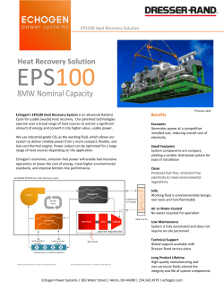


© Copyright 2026