
Government I?tin!hg Offibe. varks nwording to size
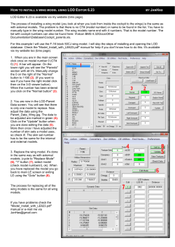
r
,:
_
_
‘/
-_
x
‘_
_.
‘-/
. ‘,
.-
‘/
\,
.,
.,
I
- \’
,-
i/
’
t
_
_’
,,
..
.I
:,
:
,
~_
‘_
-
.
_-,
: :-_
_.~. . .
-‘/
_
_
/.’
).
-
Government I?tin!hg Offibe.
varks nwording to size ,- - .’ .,
,
,,-
D. C. Yearl$ snbscription; $10; foreign.
45 cents
REPORT 1218
EFFECT
OF GROUND
INTERFERENCE
ON THE
AERODYNAMIC
AND FLOW CHARACTERISTICS
OF A 42” SWEPTBACK
WING AT REYNOLDS
NUMBERS
BJP TO 6.8 x 10”
By G. CHESTER
FURLONG
Langley
and THOMAS
Aeronautical
Lmgley
Field,
V. BOLLECH
Laboratory
Va.
I I IllII III
National
Advisory
Headquarters,
Committee
1512 H Street NW.,
for Aeronautics
Washington
2ti, D. C.
Created by act of Congress approved March 3, 1915, for the supervision and direction of t,he scientific study
was increased from 12 to 15 by act
of the problems of flight (U. S. Code, title 50, sec. 151). Its membership
The
members
are appointed by the President,
approved March 2, 1929, and to 17 by act approved May 25, 1948.
and serve as such without compensation.
SC. D., Massachusetts Institute of Technology, Chairman
JEROME C. HUNSARER,
LEOX.&RD CARMICHAEL,
PH. D., Secretary,
L.
JOIIN TV. CROMLIY,
DRYDEN,
JOHN F. VICTORY,
PH. D.,
Director
JR., B. S., Associate
Director
HENRY
J. E. REID,
SMITH J. DEFRAKCE,
D. Eng.,
D. Eng.,
for
II
.___.
-
C. WILLIAMS,
EDWARD H.
Research
Director,
Langley
Director,
EDWARD R. SHARP, SC. D., Director,
WALTER
T-ice Chairman
DONALD L. PUTT, Lieutenant
General, United States Air Force,
Deputy
Chief of Staff (Development).
DONALD A. QUARLES, D. Eng., Secretary of the Air-Force.
ARTHUR E. RAYMOND, SC. D., VicepPresident-Engineering,
Douglas Aircraft
Co., Inc.
FRANCIS W. REICHELDERFER,
SC. D., Chief,
United
States
Weather
Bureau.
LOUIS S. ROTHSCHILD, PR. B., Under
Secretary
of Commerce
for Transportation.
NATHAN F. TWINIX;~, General,
United
States Air Force, Chief
of Staff.
JOSEPH P. AD-&MS, LL. B., Vice Chairman,
Civil Aeronautics
Board.
+~LLEN V. ASTIN, PH. D., Director,
National Bureau of Standards.
PRESTON R. BASSETT, RI. A., Vice President,
Sperry Rand Corp.
DETLEV W. BRONK, PH. D., President,
Rockefeller
Institute
for
Medical Research.
THOMAS S. COMBS, Vice Admiral,
United States Navy, Deputy
Chief of Naval Operations
(Air).
FREDERICK C. CRAWFORD, SC. D., Chairman
of the Board,
Thompson
Products,
Inc.
RALPH S. DAMON, D. Eng., President, Trans World Airlines, Inc.
JAMES H. DOOLITTLE, SC. D., Vice President,
Shell Oil Co.
(2.4~~ J. PFIN~STA~, Rear Admiral, United States Navy, Assistant
Chief for Field Activities,
Bureau of Aeronautics.
HUGH
Slnithsonian Institution,
Aeronautical
Ames Aeronautical
Lewis
B. S., Chief,
Flight
High-Speed
Propulsion
Flight
D.,
Execzctil,e Secretary
CHAMBERLIN,
Laboratory,
Langley
Labora.torr,
3Ioffett
Laboratory,
Station,
LL.
Field,
Field,
Cleveland,
Edwards,
Emxuti~~e 0,ficer
Calif.
Va.
Calif.
Ohio
REPORT
1218
EFFECTOFGROUNDINTERFERENCEONTHEAERODYNAMICAND
-OF A 420 SWEPTBACK WING AT REYNOLDS ‘NUMBERS
up
FLOW CHARACTERISTICS
TO 6.8xio~t
Rp G. CHESTERFURLOS~:and THOMM V. BOLLECH
SUMMARY
The eflects of ground interference
on the aerodynamic
characteristics
of a 42” sweptback
u&g
have been investigated
at
distances
0.68 and 0.92 of the mean aerodynamic
chord from
the simulated
ground to the 0.25chord
point of the mean aerodynamic
chord.
Survey data behind the zuing, both with and
without the simulated
ground, are presented in the form of contour charts of downwash,
sidewash, and dynamic-pressure
ratio
at longitudinal
stations
of 2.0 and 2.8 mean
aerodynam,ic
chords behind the wing.
The nature and magnitudes
qf the cfpcts of ground ilzterference on the aerodynamic
characteristics
of the sweptback
wing are, in general, comparable
to those obtained on unswept
wings.
The longitudinal
stability
at the stall for the sweptback
wing with and without$aps
de$ected was not materially
aflected by the presence of the ground for the ground heights available
in the tests.
The qualitative
results qf the airstrecr.m su.rl’ey for the groundout condition
are, in general, con.xisten,t with the results which
would be expected -from a co,lsideration
of the span loading of
It was -found u/so that without
the groun.d
sweptbark
wings.
present the tip uortices for the plain wirlg wPre shed at n position
that would be expected for a straight tnl)prerl wing.
The variations
qf average downwash
am1 average dymamicpressure ratio with angle of attack indicate that,.for either model
configuration.,
the most preferable
tail location
would be below
the chord plane extended and at the most rearward
suruey position.
In the presence qf the ground,
negative uariations
of
average downwash
wi.th angle of attack were obtained, and although such variations
would increase the degree of stability,
they may be undesirable
from the standpoint
of trim.
The li$+ing-line
procedure
used for calculating
the downwash
behind unswept
wings has been extended to include the @ects
Calculations
of downwash
by the lifting-line
method
of sweep.
(as applied)
underestimated
the experimental
downwash
at the
plane of symmetry
but resulted in reasonable
estimates of the
experimental
downwash
outboard of the plane of symmetry.
INTRODUCTION
Certain aspects of the effects of the ground interference on
the aerodynamic
characteristics
of unswept wings have been
thoroughly
investigated
both
theoretically
and experimentallv
(refs. 1 to 6). The experimental
results of these
tCombination
of the recently
deolsssitlod
NACA
RM
LSQ22,
Without
a Simulated
Ground”
by 0. Chester
Furlong
and Thomns
back Wing”
by ct. Chester
Furlong
and Thomss
V. Bollech,
1951.
I
“Downwash,
V. Bolleeh,
Sidewash,
and
1948 and NACA
investigations
have shown that, in the high-lift
range,
theoretical
calculations by existing methods do not provide
either a reliable estimate of the m.agnitude of the ground
effects or an explanation of the phenomena involved
at the
stall.
Extensive theoretical and experimental
studies have been
made of the flow behind straight wings with the result that
reasonable
estimates
of the flow inclination
and wake
characteristics
can be made for a straight wing either with
or without thr ground prcscnt (rcfs. 5, 7, and 8). Theoretical
and c~xpc~rimcntal studies of the flow behind sweptback wings
arc, at present, limited in scope and, hence, no adequate
means for proper cmpcnnagc design exists. The experimental
data that arc available for sweptback wings were obtained
without the ground present and at relatively
low values of
Reynolds number (for example, ref. 9). Some large-scale
data have been published in reference 10.
Inasmuch as extensions of theoretical calculations into the
high-lift rangcx are not rcliablr and the available espcrimental
data in that high-lift range a~‘(’confined to wings having little
or no swccpback, it appears t#hat a knowledge of the effects
of the grolmtl
OIL
a
highly swcptback
wing can only be
acqukd
by means of cspr,rimrnt.
Accordingly,
an investigation has been conduct:,tl in the Ilangley 19-foot pressure
tunnrl to cletcrminc the effects of ground interference on a
highly sweptback wing and to indicate whether the ground
effects on a sweptback wing are of the same general nature
These tests
and magnitude
as those on an unswept wing.
were to provide not only additional flow-inclination
and wake
data behind a swcptback
wing not in the presence of the
ground but also flow data obtained with the wing in the
presence of the ground.
The model used for the present investigation
had 42”
sweepback of the leading edge, an aspect ratio of 4.01, a
taper ratio of 0.625, and NACA
641-112
airfoil sactions
normal to the 0.273-chord line. Tests were made with and
without a simulated ground for two model configurations;
namely, the plain wing and the wing with inboard trailingedge split flaps and outboard leading-edge
flaps deflected.
The present report contains
force and moment
data
obtained
throughout
the angle-of-attack
range at several
values of Reynolds number and contour charts of downwash,
sidewash, and dynamic-pressure
ratio at two longitudinal
Wake
Surveys
Behind
a 42’ Sweptback
TN 2487, “Effect
of Ground
Interference
Wing
at B Reynolds
on the Aerodynamic
Number
of 6.8X10 0 With and
Characteristics
of a 42’ Swept-
1
.--
-_
_.:
-...
. . .+..a*..~-
--.
.
-.
--
2
REPORT
12 1 g--NATIONAL
ADVISORY
stations behind the wing (2.0 and 2.8 mean aerodynamic
chords).
The locations of the tip vortices have been shown
on the contour charts of dynamic-pressure
ratio for the plain
Integrations
have been
wing without the ground pressnt.
made to obtain variations of average downwash and dynamic
pressure with angle of attack.
Values of downwash have
been calculated by extending the method present.ed in references 7 ancl 8 to account for the sweep of the 0.25-chord
line.
The ground was sim.ulated in the tunnel by m.eans of a
ground board.
Although
this method of ground representation is not ideal, the results of the present tests are believed
to be indicative
of t,hc ground-interference
effects on a
swcp tbnck wing.
COMMITTEE
Integrated
FOR
air-stream
average qJq, obtained
Go
average
number,
pressure, q,
lb/sq ft
pvc
~
P
wing area, sq ft
wing span, ft
local chord, ft
612
mean scrod)-namic
by
chord of fictitious tail
span of fict.itious tail
area of fictitious tail
spanwise distance
rate of change of cat,with angle of attack
l*
’ PS
Drag
drag coefficient, ~
qs
pitching-moment
coeficicnt
about O.25c,
Pitching moment
qsc
angle of attack of wiiig root chord, deg
Reynolds
e, obtained
by
where
lift coefficient
dynamic
surveys:
!a*/dao
SYMBOLS
free-stream
AERONAUTICS
chortl, z
2 dy, ft
sos
mass tlclnsity of air, slugs/cW ft
stream velocity, ft/scc
local stream d,vnamic pressure, lb/sq ft
local downwash angle, deg
smcep angle of 0.25-chord line, deg
siclrwash angle, inflow positive, deg
coefficient of visc0sit.v of air, slugs/ft-set
ratio of local-stream dynamic prcssurc to freestream dynamic pressure
vertical distance from chord plane cstcntlcd, ft,
longitutlinal
distance from 0.25-chord point of
root chord
vortex scmispan (always positive), ft
lateral distance from plane of s\-mnictrj-, ft
downwash factor
total induced downward velocity, ft/sec
section lift coefficient
vortex strength
calculated downwash a.ngle, cleg
downward
displacement,
measured normal to
the relative wind, of the center line of t,he
wake and the trailing vortex sheet from its
origin at the trailing edge, ft
GROUND,
GROUND
MODEL,
AND
REPRESENTATION
AND
APPARATUS
GROUND
DISTANCE
Several methods such as the reflection method, the partial
plate and reflection method, and the plate method are available for ground simulation
in a wind tunnel (refs. 4 to 6).
The most feasible arrangement
for ground tests in the
Langley 19-foot pressure tunnel is the plate method (commonly referred to as the ground-board
method).
The vertical distance from the 0.25C to the ground boarcl
(regardIess of boundary-layer
thickness on the ground board)
is referred to as the ground distance.
Inasmuch
as no
standard point of reference exists, the 0.25’i has been used
because it. was the most convenient point of reference from
considerations of test procedure. The model was supported in
the tunnel at the 0.25Z, and to maintain a constant ground
distance for any other point of reference would have necek
tntecl moving the ground board as the angle of attack of t,ht!
wing was changed.
Based on tbc preceding tlcfinition of ground distance, tbc
ground distances used in the present tests were 0.68Z and
0.92;.
MODEL
The model mounted on the Ilormal wing-support
system
of the Langley 19-foot pressure tunnel is shown in figure 1.
The wing had 42’ sweepback of the leading edge, a tape1
ratio of 0.625, an aspect ratio of 4.01, and NACA G41-112
airfoi1 sections normal to the 0.27khord
line. The principal
tlimcnsions of the motlcl and flaps arc given in figure 2. It,
was found that a slight discontinuity
existed along the 0.20chord line of the wing.
Tl lc results obtained in the present
tests, therefore, do not necessarily represent. exactly those
which would bc obtainccl on a wing with true NACA 641-1 12
airfoil sections.
The model was maintained
in a, smooth
condition during the tests. For tests with flaps deflected,
the 0.20~ t,railing-edge split flaps were deflected 60” from t.he
lower
surface
leading-edge
and extended
flaps extended
from
the root
to 0.50%.
spanwise from 0.400:
The
to 0.975%.
-
GROUND
(a) Front
FIGUU
1.-A
pressure
distance,
INTERFERENCE
EFFECTS
ON
SWEPTBACK
3
WINGS
(b) Rear view.
view.
42O sweptback
wing mounted
in the Langley
tunnel.
Flaps
deflected;
ground
board
in.
0.92?.
FIGURE
19-foot
Ground
l.-Concluded.
64,-I I2
sections
-34.125
: ------------Flap loins upper surface
:
approximately
l/2 inch behind L.E
-‘:50
diameter
FIG~JRE
2.-Layout
of 42O sweptback
wing.
(All dimensions
are in inches.)
-
4
REPORT
12 1 S-NATIONAL
ADVISORY
COMMITTEE
FOR
AERONAVTICS
APPARATUS
The aerodynamic
forces were measured by a simultaneously recording, six-component
balance system.
Survey apparatus.-The
Langley
19-foot-pressure-tunnel
survey apparatus and multiple-tube
survey rake (fig. 3) were
used to obtain downwash and dynamic pressure behind the
wing.
The multiple-tube
survey rake consists of six pitotstatic tubes with pitch and yaw orifices in the hemispherical
tips. The survey apparatus maintained
the rake in a vertiThis
cal position as it was moved laterally along the span.
survey rake had been previously
calibrated through known
All pressure leads were conducted to
pitch and yaw angles.
a multiple-tube
manometer
and during the tests the data
were photographically
recorded.
A probe containing
three tufts spaced 1.5 inches was used
to locate the tip vortex.
The probe was attached to the
survey strut.
Ground board.-The
ground board consisted of a steel
framework
covered with plywood on both the upper ancl
lower surfaces, which resulted in an overall thickness of 4
inches.
(See fig. 4.) A s1o t extending the full width of the
grouncl board and. located 1 foot in front of the 0.25C of the
wing was provided as a means of boundary-layer
control.
The ground board was supported in the tunnel test section
by means of wall brackets and center posts.
(See figs. 1 and
4.) The support system allowed a ground-board
travel from
16.0 to 31.9 inches below the center line of the tunnel (center
of rotation of the model).
1 F IGURE
Static
I
“‘Yaw
3.-Langley
r
orifice
orifice
/Y
I
(a) Photograph
of survey rake.
(b) Sketch of survey-rake
tube.
14foot
pressure
tunnel
airstream
survey
0-l
ldaryslot
-of
Direction
oir flow
(Center of rotation)
B -2
Section
FIGYRE
4.--Sk&h
of 42” sweptback
wing and ground
board
“.3lot
A-A
used iu the Langley
View
B-B
flap
14foot
pressure
tunnel.
Gromld
distancr,
O.GS?.
rake.
II
GROUND
TESTS
AND
INTERFERENCE
EFFECTS
CORRECTIONS
TESTS
The air in tb.e tunnel was compressed to approximately
33 pounds per square inch absolute for all tests. The tests
were made at Reynolds numbers up t.o 6.8 X lo6 (based on
a), which corresponded
to a dynamic pressure of approximately 80 pounds per square foot and a Mach number of 0.14.
==i Exploratory tests--An
exploratopy*investig&.tion
tias Conducted to determine the flow characteristics
on the ground
board a.nd in the tunnel test section both with and without
the model in the tunnel.
The change in velocity distribution
in the tunnel due to the
ground board was determined
with the ground board in the
tunnel and the model out.
Measurements
of the flow beneath the board indicated tb.at the increase in flow due to
the presence of the model was hardly measurable; b.ence the
usual moclel blockage correction
has been applied to the
dynamic-pressure
measurements.
The ground board reduced
the tunnel-clear
stream angle approximately
0.15’.
Visual tuft studies of the flow on the ground board with the
boundary-layer
slot closed and open were macle through the
angle-of-attack
range of the model.
When the slot was
closrtl but not completely sealed, an unsteady flow condition
existed along the nose of the slot. The flow condition at the
nose of the slot was improved when the slot was open.
An
unsteady flow condition existed in an area near the center of
the board between 2.OC and 2.8C with either the slot open or
This unsteady flow conclition can be attributed
to
clostd.
the diffusion of the flap wake.
There was no indication
of
actual flow separation on the board throughout
the angle-ofattack range of the moclel.
By use of the boundary-layercontrol slot the maximum
thickness of the boundary
layer
was reduced from approximately
1 .O inch to 0.4 inch beneath
tbe wing and from 1.6 inches to 1.0 inch at a distance 2.8;
rearward of the 0.257. The flow through the slot was not,
matcrin.lly affected by the presence of the model.
The discontinuity
in bounclary-layer
thickness
due to the flow
through the slot corresponcls to an effective discontinuity
in
ground distance, which, however, is believed to have a negligible effect on the test results.
Presence of a boundary layer
on the ground boarcl may be less troublesome under a sweptback wing than under an unswept wing, mainly because the
maximum lift is considerably
lower for the sweptback wing.
Force and moment tests.-Force
ancl moment data were
obtained for the two model configurations
through an angleof-attack rnnge from -4’ t,hrough the stall.
The tests were
made with the grouncl boarcl out and with the ground board
located at ground distances of 0.6% and 0.92-E for several
values of Reynolds number.
The Reynolds numbers of the
test,s based on C were 3.0, 4.3, 5.2, ancl 6.8 X 10⁶.
Airstream
surveys.-Downwash,
sidewash, and dynamicpressure surveys were macle for each model and groundboard configuration
at two longitudinal
stations.
The positions for t.he survey apparatus were selected so that they
npprosim.ated,
through the angle-of-attack
range of the tests,
stations 2.OC and 2.G behind the 0.25C of the wing measurecl
The maximum
variation
along the chord plane extended.
of the stations 2.OC and 2% from t’he locations of the survey
apparatus
was only 0.5 inch through
the angle-of-attack
ON
SWEPTBACK
5
WINGS
range of the test. Due to the fact that the trailing edge of
the wing was swept back, the distance between the survey
rake and tb.e trailing edge of the wing decreased as the rake
was moved from the plane of symmetry.
Data were obtained at three angles of attack for the wing with flaps neutral and at four angles of attack for the flapped wing.
The
angles of attack for the tests in the presence of the grouncl
were selected-so that the values of lift-_coef&ient
obtained
were of approximately
the same magnitude as those obtained
with the ground board out.
In conjunction
with the airstream surveys, the tip-vortes
core was located by observing the rotational,movement
of a
wool tuft on a probe.
CORRECTIONS
TEe lift, drag, and pitching-moment
data have been corrected for support tare and strut interference as determinecl
from tare tests. The angles of attack, drag data, and
moment data have been corrected for jet-boundary
effect’s.
In addition,
the angles of attack have been correctecl fox
airstream misalinement.
The airstream-survey
data have been corrected for jet
boundary
effects which consist of an angle change to the
downwash
Ae and a downward
displacement
of the flow
field.
The magnitude
of the angular corrections A.E at the
t,wo survey stations are given in the following table:
Longitudinal
survey position
~-_____--~
Ae
2.01
2.8;
1.36Cr.
1.53cr,
7x
-m
With the ground board in the tunnel test section, it was
not possible to obtain corrections for support-tare
and st.rut
The ground-board-out
corrections for supportinterference.
tare and strut interference,
however, have been applied to
the ground-board-in
clata in the belief that they would be
of the same nature, although
not necessarily of the same
magnitude,
as would be obtained with the ground board in.
Calculations made for other ground investigations
(such as
ref. 4) have shown that at small ground heights, jet-boundary
corrections
are negligible; hence, they have been neglect,ecl
in the present tests.
EFFECTS
OF
GROUND
INTERFERENCE
A discussion of the concepts of ground interference appears
pertinent
before the results of the present tests of a sweptback wing are presented.
Although the concepts have been
derived largely to explain the effects of grouncl interference on
an unswept wing, they should, in general, apply to a swept’back wing as well.
The ground effect on a wing may be considered as the
interference
due to the reflected image of the wing in the
ground.
Computations
of the effects of the image wing on
the real wing can be made by replacing it with a bound
vortex and a system of trailing vortices.
Inasmuch as these
computations
are based on thin-wing
theory, the effect of
the thickness of the image wing must also be determined.
The separate effects of the bound vortex, trailing vortices,
6
REPORT
12 1 S-NATIONAL
ADVISORY
and wing thickness can then be added.
In reference 1 the
interference from the trailing vortices of the image wing was
considered in detail; whereas in reference 6 the interferences
from the bound vortex and wing thickness of the image wing
were also considered.
Although
the calculations
of the
separate interference
effects for unswept wings have been
shown experimentally
to be inadequate in the high angle-ofattack range, the separate effects may be used to describe
qualitatively
the combined effects of angle of attack and
ground distance.
The image trailing vortices induce an upwash at the wing
which is st,ronger at the center than near the tips. Figure
5 (a) shows the trailing vortices of the wing and the image
c=
========------=__----____===
==1
=cl
0
(0)
Cc)
(b)
(d
W
(a) Trailing
(b) Bound
(d)
vortex (low angle
of attack).
Wing thickness doublet
(low angle of attack).
FIGUHE
5.-Sketch
image
vortices.
(c) Bound
vortex (high
of attack).
angle
(e) Wing thickness doublet
(high angle of attack).
showing
the interference
effects of the
of a wing iu the presence of the ground.
reflected
vortices.
The main effects resulting from this vortex pattern are an increase in lift-curve slope, a reduction in induced
drag, and a concentration
of lift toward the center of the
wing.
The effects are increased by decreasing the ground
distance and are relatively independent of the angle of attack.
The induced flow over the wing due to the image bound
vortex is shown by a side view of the wing and its image
(fig. 5 (b)). The flow, which is from rear to front, reduces
the stream velocity in the vicinity of the wing and thereby
tends to reduce the lift. If, however, the wing is fairly close
to the ground, is at a low or moderate angle of attack, and is
COM3II’ITEE
FOR
AERONAUTICS
uncambered,
the induced flow also has a vertical component
near the rear (fig. 5 (b)), which corresponds to an effective
increase in camber and a corresponding
increase in lift,. As
either the angle of attack or the camber is increased, however, the induced flow crosses the wing from above (as in fig.
5 (c)) with a corresponding
effective decrease in camber
and reduction in lift. For a highly cambered airfoil, such as
a flapped wing, this effect is very pronounced.
The decrease
in camber and reduction in lift as th.e angle of attack is increased is also a function of ground distance.
As the ground
distance becomes very small, t,he effects mentioned
are delayed to higher and higher a.ngles of attack.
The thickness of the image wing may be roughly represented by a source near the airfoil nose and an equivalent
sink near its trailing
edge.
The corresponding
streamlines
are circles through
the source and sink, as indicated
in
figures 5 (d) and 5 (e). The velocity is in such a direction
as to increase the stream ve1ocit.y in the vicinity of t,he wing.
The induced flow (figs. 5 (d) am1 5 (e)) is seen to be essentially independent
of angle of attack and is downward
near
the trailing edge and upward at the nose. This induced flow
corresponds to a negative induced camber and a reduction
in lift.
The induced-flow
effect of the doublet is increased
as the ground distance is reduced, but in any case this effect
is small compared with the induced-flow
effect of the bound
vortex (figs. 5 (b) ancl 5 (c)).
In general, the induced flows indicated in figures 5 (a),
5 (b), 5 (d), and 5 (e) serve to increase the slope of the lift
curve.
As the angle of attack and lift coefficient become
very large or when the flaps are deflected, the induced flow
indicated
in figure 5 (c) becomes increasingly
strong and
serves to reduce the lift-curve
slope.
The overall influence
of these effects on the maximum
lift is too complex to be
explained without a more quantitative
analysis.
Experimental
results provide
some indication
of the
important
factors det,erminiug
the maximum
lift as the
ground is approached.
Data for straight, unflapped wings
(refs. 1 ancl 6) show that the nmximum lift is decreased and
then increased as the gound is approached.
Thr reduced
stream velocity and t.he negative induced angle and camber
indicated in figure 5 (c) appear to combine with the small
induced flow of figure 5 (e) to effect a decrease in maximum
lift at moderate ground distances.
As previously mentioned,
the negative induced angle and camber effect (fig. 5 (c)) are
reduced appreciably
for uncambered
wings as the ground
distance bccomcs small; hence the maximum
lift. begins to
increase.
The experimental
data
for straight,
flappccl
wings (ref. 4) show a decrease in maximum lift at all grouncl
distances down to 0.5G.
In t,his case the wing is originally
very highly cambered and the negative induced angle and
camber indicated in figure 5 (c) are not materially
decrcasecl
by a decrease in ground distance.
For sweptback
wings most of t.he effects just describccl
would probably
remain the same. With regard to the
spanwise distribution
of loading, however, calculations
made
as a part of the present invest,igation
have indicated
that,
when the effect of the swept bouncl vortices is included with
the effect indicated in figure 5 (a) (calculated in ref. l), the
induced upwash distribution
should tend to concentrate
the
GROUND
INTERFERENCE
EFFECTS
ON
SWEPTBACK
7
WINGS
-i
I i///i
I i
Ground distance
+CXl
8
12
-4
0
16
4
20
8
24
-4
12
0
16
4
20
8
24
12
-4
16
0
4
20
8
24
I2
16
a, deg
20
24
(a) Lift.
lJrc:~.m
6.-1~Iffwt
of ground
011 the atwxlynamic
characteristics
of a 42’ sweptback
loading near the tips instead of near the center.
This
effect, combined with t,he fact, that the tip sections of a
swcptback wing arc much closer to the ground than the root
sections, woulcl be expected to result in a noticeable outboard shift in load.
The tip stall usually associated with
sweptback wings might bc increased in severity by such an
outboard shift in load.
RESULTS
AND
LIFT-CURVE
numbers.
Flaps
neutral.
1.0
.8
.6
1.2
.4
1.0
.2
.8
0
.6
1.2
-.2
.4
1.0
-.4
.2
.8
CL
0
SLOPE
.6
The slope of the lift curve near C&=0, for the wing with
flaps bot,h neutral and deflected 60°, increased as the distance
to the ground decreased (figs. 6 (a) and 7 (a)). The increase
is, in general, comparable
to the increase obtained for an
unswept wing with flaps neutral (ref. 4). The data do not
indicat.e a shift in angle of zero lift.
Such a shift is indicated
by the theory and test data for an unswept wing presented
in reference 6. No such shift, however, was indicated by
the unswept-wing
data of reference 4. The reduction
in
lift-curve
slope attributable
to ground interference
in the
high angle-of-attack
range was much more severe for the
flaps-deflected
configuration
(fig. 7 (a)) than for the flapsneutral configuration
(fig. 6 (a)).
MAXIMUM
Reynolds
1.2
DISCUSSION
The lift, drag, and pitching-moment
data are presented in
figures 6 and 7. Tho stalling characteristics
arc presented
in figures 8 and 9.
The greater part of the present discussion is for data
obta,ined at a Reynolds number of 6.8X10⁶.
wing for various
-.2
1.2
.4
-.4
1.0
.2
8
0
.6
-.2
.4
-CO
-.4
.7
0
.04 .08 .I2
.I6
.20 .24 .28 .32 .36 .40
‘0
LIFT
(b)
The data of figure 6 (a) for the wing with flaps neutral
show an increasing maximum
lift coefficient at the ground
Drag.
FIQURE 6.-Continued.
346184-5L2
-
__-_-
-..-1m--m.-m ... . 111111.
I
IIll
8
. REPORT
.04
-
1218-NATIONAL
ADVISORY
COMMITTEE
FOR
AERONAUTICS
distances of the present tests (less than l.OE). The data’of
the present tests do not extend to sticiently
high ground
distances to show whether a sweptback wing will sustain
a loss in maximum
lift when first entering the presence of
the ground.
Both the magnitude of the increase in maximum
lift and the magnitude of the ground distances at which the
increase in lift is obtained appear to be greater than the
magnitudes obtained for unswept wings (refs. 4 and 6). It
should be remembered, however, tliat the points of reference
used to determine
the ground distances for a sweptback
wing and an mlswept wing are not directly comparable.
The data for the sweptback
wing with flaps deflected
(fig. 7 (a)) show an appreciable loss in maximum lift at the
same gound distances at which increases in maximum
lift
were obtained for the flaps-neutral
configuration
(fig. 6 (a)).
The decrease in maximum lift at small ground distances is
in general agreement with the results obtained on unswept
wings with flnps deflected (ref. 4).
0.92 c
.68C
DRAG
-.04
-.4
-.2
.2
0
.4
(c) Pitching
FIGURE
.6
23
1.0
1.2
A reduction in drag (figs. 6 (b) and 7 (b)) was obtained
when both model configurations
wcrc tested in the presence
of the ground board.
Throughout
the comparable
lift
range the model with flaps deflected encountered
slightly
larger decreases in drag than were cncountcrcd
with the
flaps-retractecl
configuration.
The reductions
in drag are,
in general, comparable
with the rctluctions
obtained
for
unswept wings (ref. 4).
1.4
Inoment.
6.-Concluded.
.
_
I-
*
._---
-
_
+
-~
-~
c--
-
0.92?
-
-
-
.68C
_---
i-
_~.___~~_
,
0
4
~-- 8
-4
12
0
16
4
20
8
24
-4
12
0
16
4
--J
20
8
24
12
16
20
,,
I
24
a, deg
(a) Lift.
FIGCRE
7.--Effect
of ground
on the arrodgnamic
characteristics
of a 42” sweptback
wing
for various
Rr,vnolds
nlunhers.
Flaps
deflect&
60”
GROUND
INTERFERENCE
EFFECTS
ON
SWEPTBACK
9
WINGS
-.04
-.08
-.I2
0
llllillllllll
-.04
-.08
Ground distance
-
-
.60 C
-
R=5.2x10⁶
:
I
.
.
0
.04
.08
.I2
.I6
(I))
IiI(:uim
STALLING
.20
.24 .28
CD
.32
.36
.40
Drag.
L
’
”
1
,
/
.-
I
’
’
1
I
1 I-
7.-Continwcl.
PATTERNS
MOMENT
The prcscnce of the grouucl did not materially
affect the
longitudinal
stability at the stall for either model configuratiou of the sweptback wing.
The wing with flaps neutral
remaiued mlstable (fig. 6(c)) at the stall ancl the wing with
flaps cleflccted remained stable (fig. 7(c)).
At the lowest
ground distance (O.SSC), a noticeable clest.abilizing change in
pitching-moment
slope in the lift-coefficient
range just prior
to stall was obtained for the flaps-deflected
configuration.
These effects are similar to those reported for an unswept
wing (ref. 4).
It appears from the present data that, at t,he ground distances of the present tests, the outboa.rcl shift in load that
might be expected with a swcptbaclr
wing is effectively
counterbalanced
by the increase in effective camber and by
a reduction in aclverse pressure graclients at the tip sections.
The net result is that the origin and progression of the stall
1
1
.44
‘l’l~c results of the visual stall observations
(figs. S and 9)
shon- that, for the configuration
n-it11 flaps dcflcctctl,
the
prcscllcc of tllc groun~l prccipitatctl
a stall on the uppc~
surface of tllc wing at a sliphtl~- ion-cr angle of attack.
Stall
studies with the gromltl board out arc not available for tile
wing with flaps neutral.
The stall studies indicate that, in
geiicral, the origin and progression of the stall are little affectctl by the prescncc of tllc ground.
PITCHING
-.
Ground distance
.
,
c,
(c) Pitching
FIouItls
moment.
7.-concludetl.
arc little afIected by the presence of the ground and hence
the stability
at t.he stall is not changed.
The possibility
of severe tip stalling and accompanying
instability
at the
stall for the sweptback win, 0‘ at ground distances greater
than those of the present tests could not be ascertained and
remains a problem to bc investigated.
SCALE
EFFECTS
I?or the configuration
with flaps neutral, there appears to
be some scale effect on the lift in the high-lift and stalling
Because of this effect, the stabilizing
change in
region.
pitching-moment
slope obtained at a lift coefficient of 0.8
for a Reynolds number of 3.0x10⁶ is clelayed to a lift coefficient of approximately
1 .O at a Reynolds number of 6.5 X lo6
(fig. 6(c)).
The slight improvement
in the stability
at the
stall, which is obtained for the smallest ground distance and
a Reynolds number of 3.0X loo, is not obtained at a Reynolds
The effects of Reynolds number on
number of 6.SX106.
the lift, drag, and pitching momen& for the wing with flaps
deflected (fig. 7) appear to be small.
10
- REPORT
\L
Yq
12 1 S-NATIONSL
ADVISORY
COMMITTEE
FOR
AERONAUTICS
Intermittently
stalled
Cross flow
Completely
stalled
1.6
T
*
+
_
.
cL .8
_
.4
24
32
0
8
a, deg
(a) Ground
FIGURE %--Effect
distance,
of ground
(b)
0.92.5
on the stalling
16
a, deg
characteristics
of a 42O sweptback
wing.
24
Ground
Renolds
distance,
number=6.8X
32
0.68;.
10R; flaps neutral.
GROUND
i\\
q
-y
cross
INTERFERENCE
EFFECTS
ON
SWEPTBACK
Intermittently
stolled
flow
11
WINGS
Completely
stalled
1.6
16
cL .8 -
cL .8
.4 L
8
0
16
P. d??
24
0
:
(0)
24
16
a. deq
32
8
16
a. deq
24
32
(b)
(a) Ground
FIGIJRE
8
>
9.-Effect
distance,
of ground
(b)
m.
on the stalling
-
characteristics
Ground
distance,
(c) Ground
0.92?.
of a 42’ sweptback
wing.
-
Reynolds
number=6.8X
distance,
0.6%.
lOA; flaps deflected
----_...-
60”
-
12
REPORT
AIRSTREAM
12 18-
NATIONAL
ADVISORY
SURVEYS
The airstream-survey
data have been cross-plotted
to
obtain contour charts of dynamic-pressure
ratios, downwash,
and sidewash in vertical planes 2.0; and 2.8Z behind the
0.25:.
The charts are presented in figures 10 to 21 and, for
reference, the data presented are summarized in table I.
TABLE
LIST
OF
I
DOWNWASH
ANGLE,
SIDEWASH
AND DYNAMIC-PRESSURE-RATIO
CONTOUR
CHARTS
PRESENTED
I
10
I A-eutrs1..
14
Neutral..
m
/
....
--_____-
Neutral
18
I
. ..-..
.......
-__~--
I
O.YE
2.0:
2.OF
-!
O.BS?
/
02
-I
Xeutral..~..
/
11
i
2.8F
.‘-
(a)
(0)
(c)
IL(a)
(bl
(c)
I
!
a=7.90;
a=13.10:
u=16.0°:
ANGLE,
(“=0.51.
CI,=O.81.
CL=O.Yi.
or=6.7":
C~=0.48.
o1=11.9’;
&=0.80.
u=14.6”;
CL=O.95.
I
I
I
-/
(a) or=6.7';
&=0.51.
(b) o1=11.9”;
CL=O.%
(c) 01=14.6”;
CL=O.98.
(a) or=i.gO;
(b) a=13.1’;
(c) e16.0’;
C~=0.51.
C~=0.81.
&=0.97.
I
(a) or=6.7'=; C~=0.51.
(b) 01=11.9~; Ck=O.S?.
(c) or=14.6'=; C,s=O.98.
I
15
19
2.8:
0.68P
-1
-__
Deflected..
12
_
(d)
-~
I-
or=16P:
C,,=l.R5.
I
^__---
AERONAUTICS
The contours of dynamic-pressure
ratio, downwash, and
sidewash have been shown with reference to the chord plane
extended.
The intersection
of the chord plane extended
with the plane of survey has been arbitrarily
selected as the
reference line and any horizontal tail will remain a constant
distance from this line as the angle of attack of the wing is
changed.
In order to indicate the position of the flow field
of the wing with respect to the wing, the 0.25-chord line of
the wing has been projected onto the plane of survey in the
contours of dynamic-pressure
ratio.
The qualitative
results of the airstream survey for the
ground-out
condition are, in general, consistent with the results which would be espected from a consideration
of the
spanwise lift distribution
associated with sweptback wings.
The spanwise lift distribution
for the wing with flaps neutral,
computed by the empirical method presented in reference
11, indicates that negative vorticity is shed over the inboard
sections of the wing, and hence, it should be expected that
the maximum downwash would occur outboard of the plane
of symmetry.
For an unswept wing of the same taper ratio,
the lift would increase to the plane of symmetry and it would
be here that the maximum
downwash is reached.
In the
present tests, the reduced downwash at the plane of symmetry
(figs. 10 and 11) is also due in part to the fact that the distance
from the wing to the plane of survey is greatest at the plane
of symmetry.
The vortex sheet is displaced downward and
the magnitude
appears to be of the same order as for unswept wings.
The wake center line traveled from just above
I
Deflcctrd.
._.
2SE
..’
13
Drllected.
li
Drflected..
O.RRF
1
_.
---
21
,
1 Deflected..
r‘=o.fi?.
CL=O.I)I.
rL=l.oo.
CL=I.FO.
u=3.60:
(‘L=n.fil.
cF8.50;
cz=o.91.
a= 17.50: (“= 1 .:a.
a=16.8’:
C,,=1.35.
2.87
0.92T
(R)
(b,
(c)
; (d)
u=2.40;
a=7.10:
a=Y.i':
rr=l?..P;
(z=O.R9.
rL=o.RS.
C~=l.04.
C,,=1.18.
0.68:
1 (a) 01=2.4':
(h) a=i.3':
(c) a=lO.o”:
! (d) a=13.R”;
C,,=O.62.
CL=O.SII.
rL=l.on.
(z=l.SO.
I
2s
/
I
(n)
(h)
CC)
(d)
m=$.40;
a=i.l’:
‘7=10.0~:
a=l3.6”:
m
--.’
(z?)
(hl
’ (-)
(d)
2.X?
I
__-__
/
The effect of the model support struts on the flow at the
survey planes was small even though tuft studies indicated
that flow separation on the struts occurred at moderate
angles of attack with the ground board present.
The regions
affected are easily discernible on the contours of dynamicpressure ratio for the plain wing as areas of reduced dynamicpressure ratio in the vicinity
deflected
the strut
to a maximum
height
of 0.17 5 a.t
-‘-------_--
___-__
,
FOR
the chord plane cxtcndcd
16
20
COMMITTEE
of 0.50%.
the wing and strut wakes
wake lost its identity.
When the flaps were
intermixed
and hence
the highest angle of attack (a=16.0°)
and most rearward
survey position (2.8;).
The a.irstream surveys behind the wing with flaps deflect,ed
60’ (figs. 12 and 13) show to some extent the strong effect of
the flap tip vortex and secondary effect of the increase in
strength of the bound vortex produced inboard by the flap
on the flow field.
The downwash is increased and the wake
is lowered behind the flapped portion of the wing.
The tip vortices, as indicated by the present surveys for
the plain wing, are shed and locabed in approximately
the
same position as would be expected for a straight tapered
In the range of the tests there is very little rolling-in
wing.
of the vortex, a fact not unreasonable when it is realized that
the distance rearward of the geometric tip is much less than
the 2.86 measured from 0.2577.
The presence of the ground for both model configurations
caused the usual reduction in downwash and upward displacement of the wake (figs. 14 to 21). Inasmuch as the reflected
tip vortex is opposite in direction to the real tip vort,cx, it
would increase the negative values of sidewash (outflow) and
decrease the positive values of sidewash (inflow).
/
-:
L..
:
GROUND
INTERFERENCE
EFFECTS
ON
SWEPTBACK
13
W INGS
- %P
-.-I .02
,
Y
--..
I
;~.25-chord
line
I
I-.
I
I
I
I I U.96
.__
I ..-..
\
<Ir5.0T
11
I
~
I
/
blli
/
l.JLS
/
(0)
/
III
20
40
Distance
from
(a)
FIGURE IO.-Contours
of downwash
60
center
a=7.9’;
line of wing,
SO
&,
percent
100
semispon
&=0.51.
and s idewash angles in degrees and of dynamic-pressure
ratio
plane of survey at 2.OZ; flaps neutral; ground distance,
behind
m.
a 42’ sweptback
wing.
Longitudinai
14
REPORT
12lY-NATIONAL
ADVISORY
COMMITTEE
FOR
AERONAUTICS
-
5
20
, I/
vi
I
\
'_-
\
/\I\
!I
'\ .--
0
_ Jo]--:-:/I
-
A
T-
,/L--&J-L
----
i
-
I\
0
--
Y
20
I--I\
IllI/
40
Distance
from
(b)
I
60
center
line of wing,
a=13.1’;
C~=0.81.
FIGURE IO.-Continued.
80
&-,
percent
semispon
wq
Ill
GROUND
.25-chord
40
INTERFERENCE
EFFECTS
line..
ON
SWElPTBACK
15
WINGS
,
T
Tip vob ex core-
s
\
3
I
,--_
---------
.I.00
I
1
\YI, -20/
P
cl
Yi
P
2
”
E
cl
.2
I
.98
I
)
‘\
‘*Woke
-_
I ---.
I
I
I
I
40
20
.5
\
I
0
--_.
__-----‘z5
.--
--__
-_-
Distance
from
center
-/72--P
line of wing,
(c) a=16.0°;
&=0.97.
FIGTJRE lO.-Concluded.
346184-56-3
h,
percent
semispon
center
line
--
16
REPORT
12 1 S-NATIONAL
.\
\
FOR
I
4.0
I/
-j
:
I
i
i
AERONAUTICS
J,
I
I
I ’.
IX
‘I/
,
I,
r-7
\ \
---
\
COMMITTEE
\
‘%
!
\’
\
ADVISORY
__. --
---.
_
----
4.0
‘i
Distance
from
(a)
FIGURE
Il.-Contours
of downwash
80
60
40
20
center
line of wing,
a=7.9O;
A,
percent
100
semispon
C~=0.51.
and sidewash angles in degrees and of dynamic-pressure
ratio behind
plane of survey at 2.8;; flaps neutral; ground distance,
=.
a 42’ sweptback
wing.
Longitudinal
GROUND
INTERFERENCE
EFFECTS
ON
SWEPTBACK
17
WINGS
-
w
/
.25-chord
line-‘.
<ip,wxtex
20
I
I
I
I
I
I
core
I
\I
7-I
,nr
/
‘x
A!?
E
%
E
s
5
4
2
.90
I
I .oo
\
.
-
-20
\
%Y
IQI
E
-0
0
I
7
20
\
\
I
I
I
I
I
I
I-1.
I
I
n
\\
\
\
\
I
II
I
IX
11
I
II
I
J.9.0
\
\
\
-7n\-
L
-20
40
Distance
60
from center line of wing, &,
(b) a=13.1”;
C,=O.Sl.
FIGURE Il.-Continued.
8
percent semispan
l
I
I
REPORT
1218-NATIONAL
ADVISORY
.25-chord
--__
------7-t-----------c----
-._
I.”
0
:-->7.0
ql-x
--i___
/’
FOR
AERONAUTICS
line----
---- -T-Y-~--__
--_
---x ‘,
8.5
7.5
COMMITTEE
-
Lr+
,I-/----,’
Distance
;
-----
-
--23
from center line of wing, &,
(c)
or=16.0”;
percent
semispon
C,,=O.97.
FIGVRE 11 .-Concluded.
-
I
GROUND
INTERFERENCE
EFFECTS
ON
SWEPTBACK
19
WINGS
I
- %P
I
I40t?I
---
20
I
0
I
\
I\\\\1
. \
20
h
\
Distance
of downwash
I
from
I
60
center
(a)
FIGURE 12.-Contours
I
40
line of wing,
a=3.6';
I
80
&,
percent
I
I
100
semispon
&=0.61.
and sidewash angles in degrees and of dynamic-pressure
ratio behind
plane of survey at 2.OF; flaps deflected 60’; ground distance,
m.
a 42’ sweptback
wing.
Longitudinal
20
REPORT
1218--NATIONAL
ADVISORY
COMMITTEE
FOR
AERONAUTICS
I
\
1.03
-
\
40
\
-
6
.-::
E
2
E
/
I /i-w
I
g
‘-Woke
I
I
center
line
I-
/%0
40.
’
s
6
.-z
D
0
.o
x5\
\
LOI
t
3
I
0
s
&
a
DL
2
L
%/Q
20-r;’
\
\ /y---/y
,,\
/
I\
\
1
\
[
mu’
\I
0
-20
’
\
5.0
(b)
0
‘;h
[-LO]
I \\
20
\
40
Oistonce
from
6 ‘0 1
center
line of wing,
(b) a=8.5’;
FIGURE
*,
CL=O.91.
12.-Continued.
Y
80
percent
semispon
100
I
GROUND
INTERFERENCE
EFFECTS
ON
SWEPTBACK
21
WINGS
wq
----i
I
I,
[Al [lip1
5:
Llnd
i
’
[3!0]
1
Ii
I
[2.0] 1
I
4----’
1
!
I
I
I ! I;
----
[CT]
c
I
I
I
I
I ‘-.
I
I
I
40
Distance
from
60
center
line of wing,,&,
(c) n=13.50;
c&=1.20.
FIGURE 12.-Continued.
percent
I
I
80
semispon
I
I
I
I
I
100
I
22
REPORT
u
5
i
2
[?I
0?
1218-NATIONAL
L2.01
II.0-
ADVISORY
COMMITTEE
FOR
AERONAUTICS
[k-y1
,
PI
I
iI II.5 17
I
I
I
percent
80
semispon
---- ru1
I----LEJI
Cd)
0
20
Distance
40
from center
60
line of wing,
(d) a= 16.8”;
C,=
FIGURE 12.-Concluded.
--&,
1.35.
100
GROUND
INTERFERENCE
EFFECTS
ON
SWEPTBACK
23
WINGS
40
‘:25-chord
Distance
from
center
line of wing,
(a) cu=3.6’;
FIGURE 13.-Contours
34618656-4
of downwash
and
&,
percent
line
semispon
C1,=0.61.
sidewash angles in degrees and of dynamic-pressure
plane of survey at 2.8E; flaps deflected 60”; ground
ratio behind
distance,
~0.
a 42’ sweptback
wing.
Longitudinal
24
REPORT
12 1 S-NATIONAL
ADVISORY
COMMITTEE
FOR
AF;RONATJTICS
J
Distance from center line of wing, &-,
(b) a=8.5’;
CL=O.91.
FIGURE 13.-Continued.
percent semispon
GROUND
INTERFERENCE
EFFECTS
ON
SWEPTBACK
I
I
I
I
I
1
I
I
I
.
25
WINGS
-
I
I
j
I
4,/g
’
\
I
I
I
I
I
I
1.02
.25 -chord
I
------
I
I
i
I
linw”
I
I
;
/
-
-1.00
I
\.- Woke center line
---t--l
I
I
I
Distance
SO
60
40
20
100
percent semispon
from center line of wing: &-,
(c) cc= 13.50; CL= 1.20.
FIGURE 13.-Continued.
.-
.._._
-..
-.
._-.-__...-_-._--.,.11
1m
I
26
REPORT
0
12 18-NATIONAL
/
\‘\I
ADVISORY
I
I
I
AERONAUTICS
I
u
.7’
/\/
I
i/
40
60
Distance from center line of wing, &-,
(d) or=16.8”;
C,=
1.35.
FIGURE 13.-Concluded.
---
FOR
\I\\
.80
_u
a
e
COMMITTEE
;I --i-T
I
80
percent semispon
100
GROUND
INTERFERENCE
EFFECTS
ON
SWEPTBACK
27
WINGS
--
4,/Q
\
.99
\
-20
.5’
t------z (a)
O\
[-g.o]7” 7
_---
[-LO]
I : \
q0j'
Distance
from
center
14.-Contours
of downwash
s
vu
line of wing,
(a) or=6.7”;
FIGIJRE
’
-&,
I
percent
!\I
K
semispon
&=0.48.
and sidewash angles in degrees and of dynamic-pressure
ratio behind
plane of survey at 2.OZ; flaps neutral; ground distance, 0.92Z.
a 42’ sweptback
wing.
Longitudinal
II
REPORT
28
1218--NATIONAL
ADVISORY
COMMITTEE
FOR
,
___---T-’
I
--.--.
40
I
/
I
I
I .95-L- I
---_
-
0
P
_o
a
P
2"
AERONAUTICS
I
I
,-.25-chord
I
/I
I
I
\
I
I
I
‘;.y
.[2.Oi
I
Distance
from
center
I ,
[3.bl
' I
\
line of wing,
(b) a=11.9’;
&Y,
percent
CL=0.80.
FIGIJRE 14.-Continued.
//
I
I
I
!
I
I
I
I
\
-..-
\
line
3.5
‘4
semispon
I
I
----
[u]
GROUND
40
I
I
I
INTERFERENCE
I
I
ON
I
I
I\I
SWEPTBACK
29
WINGS
-
I
I
I
EFFECTS
I
I
I
\
I
I
I
I
I
‘7ut/u
!
1
1
I
\
“.98
1.00
I
I
I
.25-chord
-
\I
I
line.,
I
Groundboord
(Cl 1
L-80
0
Distance
fiom
center
line of wing,
(cl a=14.6’;
6,
percent
.L --&--I
semispon
CL=O.95.
FIGURE 14.-Concluded.
IIIllIllII
30
REPORT
1218-NATIONAL
ADTWORY
COMIMTTEE
FOR
AERONAUTICS
z
Ea
- --‘[;I
\ 3f-l
-20
(0)
0
I
[-43
I
20
from
center
(a)
of dorl-nwash
1 “.“J
I
I
I
40
Distance
15.-Contours
I--
-.- -
II
61
FIGI~RE
__-
’
I
60
line of wing,
a=6.7”;
,o’
/
80
&-,
percent
I
100
semispan
C&=0.48.
and sidewash angles in degrees and of dynamic-pressure
ratio behind
plane of survey at 2%; flaps neutral; ground dist,ance, 0.92?.
a 42’ sweptback
wing.
Longitudinal
GROUND
INTERFERENCE
EFFECTS
ON
SWEPTBACK
WINGS
31
.
0
6
.-::
E
%
(b)
20
Distance
from
IILL-I
40
60
center line of wing , &-,
percent
(b) a=11.9”;
C~,,=O.80.
FIGURE 15.-Continued.
80
semispon
100
32
REPORT
12 1 S-NATIONAL
ADVISORY
COMMITTEE
FOR
AERONA’GTICS
I II II II ’-m-q
I/-
l
7+=-i&-
40
\
I I’ --
---_
20
,:
,,Woke
:goJ‘,-w
center
;
line
!
-
I
1
I
0
Groundboard
/
I
60
Distance
from.
(c)
center
line of wing,
a=14.6’;
FIGURE
Cr=O.95.
15.-Condluded.
80
&,
percent
semispan
100
GROUND
INTERFERENCE
EFFECTS
ON
SWEPTBACK
33
WINGS
-
w
40
----.z
‘[ml
40
Distance
from
center
line of wing,
&,
percent
semispan
a=2.4”;
CL=O.59.
and sidewash angles in degrees and of dynamic-pressure
ratio
plane of survey at 2.0;; flaps deflected 60”; ground distance,
(a)
FIGURE
16.-Contours
of downwash
behind
0.92;.
a 42” sweptback
wing.
Longitudinal
34
REPORT
--
121S-NATIONAL
ADVISORY
COMMITTEE
FOR
AERONAUTICS
.98-
J,
/
-[;.“I
I
b--.-A/ /f-t--T
’
w
5.0’
I
/
I
.5
/
w
:
“i”
\
\
----[m]
E
I’
\
I
I
I
L===
%O]
’’
i
3.5
\
I
T” ‘/ /
‘//
I ’
0
,
1
I
/
I /
-1.0
I
I
I
80
80
Distance
from center line of wing, &,
(b)
a=7.1’;
FIGPRE
Ch=O.S9.
16.-Continued.
percent semispan
I
I
100
100
I
GROUND
INTERFERENCE
EFFECTS
ON
SWEPTBACK
35
WINGS
40
,-
.98
20
0
--~
\
0
20
Distance
i
-
l/l./
60
from center line of wing, Ab,2,
(c)
a=9.7”;
cL=1.04.
FIGURE 16.-Continued.
I
percent semispon
I
80
I
I
100
ICI
36
REPORT
1218--NATIONAL
ADVISORY
COMMITTEE
FOR
AERONAUTICS
\
40
-
.98,
\
..25-chord
I
I
\
40
I
II
Ii
/
I
I
IT--H
1
-E
/J--5.5,
I
I
;roundboord-.
0
20
40
Distance
line
from
center
I,60
line of wing,
(d) a=12.5”;
&-,
c~=l.lS.
FIGURE 16.-Concluded.
80
percent
semispon
GROUND
INTERFFRENCE
EFFECTS
ON
SWEPTBACK
WINGS
I.01
37
-
4,/g
40
1.00
/
1
\
a
20
\
\\
-
I
-i
I1
I
1i
80
Distance
FIGURE
17.-Contours
of downwaah
from
center
line of wing,
&,
percent
semispon
(a) a=2.4’;
&=0.59.
and sidewash angles in degrees and of dynamic-pressure
ratio
plane of survey at 2.8;; flaps deflected 60’; ground distance,
behind
0.922.
100
a 42’ sweptback
I
wing.
Longitudinal
38
REPOPT
1218-NATIONAL
ADVISORY
COMMITTEE
FOR
AERONAUTICS
\
2op---===-
as
0
.L”
E
is
‘\\
,
-
.25-chord
line -._
+---Woke
center
‘\ \
-
/
line
(/:-i;Bo--
195
;u
4
\
/..---
\ ‘-/”
‘1.
5a
\
_z
2
.
-20
d
---I\
I
I/
I
.98.
/
[)“I
[:.O l
II
40
I
,
:
I
I
4.0 -,’
/
/
/
/
/I
---
!
-a.o] ,
Zmn,,,,,,**,
60
Distance
from
center
line of wing,
(b) a=7.1”;
&,
percent
I
SO
i
,,c Groundboord
I
100
semispon
CL=0.89.
FIGURE 17.-Continued.
.-
--
I
GROUND
INTERFERENCE
EFFECTS
ON
SWEPTBACK
39
WINGS
\
I .oo
-w
\
\
1.01
-
\
-
,,-:25-chord
I
line
I
\
.
-
,
[24
an
-
I
I
\ \
,-
‘\
[q
-
E
I
1
I
:+
\
‘,\
‘.
--i-
/
I.
_^
--I,,
/-- %\ ‘\ \
‘.
\\
4
.
I
I
I
1
I
/I
&I
I
-
I’
I
I
’
‘1..
\1\c-----.‘\ ---===
/
I
I
I
I
20
I
I
Distance
from
center
line of wing,
(c) a=9.70;
c,=
_-.....
._-----
.- .._..._...._ .._~
L
80
6,
1.04.
FIGURE 17.-Continued.
--
I
60
40
percent
semispon
100
.,,.,..
......,... ,
40
REPORT
, . . . . -- _..__.
.... ... .-_-_-.-._....
- . ..-----.-
12 1 %--NATIONAL
ADVISORY
COMMITTEE
FOR
._
I
AERONAUTICS
8
I
1.01
n--l-I
,c-.25-chord
/
\
\
\
\
j -)
/
I
’
”
I
I
20’
qt/g
-
,;q5-5w=L
‘\
s
::
0
0
\
\
\
\
, .9O,y-b85-
.95.
20
40
Distance
from
60
center
line of wing,
(d) a= 12.5’;
C,=
60
&,
1.18.
FIGURE 17.-Concluded.
percent
semispon
100
GROUND
EFFECTS
I
I
ON
I
I
I
I
INTERFERENCE
I
/------..---
I
I
I
L”‘Y
I
II
__
on
41
WINGS
I
I
b4
!
I
SWEPTBACK
I
-
I
-6
Groundboard--..
1
20
I
40
60
Distance from center line of wing, &,
(a) or=6.7’;
FIGURE
18.-
Contours
of downwash
80
100
percent semispan
&=0.51.
and sidewash angles in degrees and of dynamic-pressure
ratio behind
plane of survey at 2.OE; flaps neutral; ground distance, 0.6%.
a 42’ sweptback
wing.
Longitudinal
42
REPORT
12 1 S-NATIONAL
ADVISORY
COMMITTEE
I
FOR
AERONAUTICS
\
I
I
G/q
-
/i--.98,
E
1
I
I
I
I
I.00
0 +---j----.96
In
E
$
j
I
.95--c/
\I/
\,
(b)
0
20
40
Distance
from
(b)
60
center
line of wing,
a=11.9”;
80
-&
C~=0.83.
FIGURE 18.-Continued.
percent
semispan
100
GROUND
r
c0E
i
40
3
c
D
‘,
n
\
EFFECTS
ON
SWEPTBACK
WINGS
I
I-
\\
\
\
\
[yl
!
/
3.0
\
0
.
\
INTERFERENCE
43
. .a
-E
3.5’
\
’
\
(.
4.0
(
‘.
20
40
Distance
from
(G)
60
center
a=
line of wing,
14.6’;
CL=O.98.
FIGURE 18.-Concluded.
80
&,
percent
semispan
100
I
44
REPORT
1
12 IS-NATIONAL
1
ADVISORY
/
Distance
1
from
of downwash
FOR
AEROt’JAUTICS
Grouny board
center
lme ot wng,
(a) a=6.7”;
FIGURE lg.-Contours
COM$WL’TEE
&-,
percent
semispon
C~=0.51.
and sidewash angles in degrees and of dynamic-pressure
ratio behind
plane of survey at 2.G; flaps neutral; ground distance, 0.6%.
a 42” sweptback
wing.
Longitudinal
GROTJND
INTERFERENCE
EFFECTS
---
ON
SWEPTBACK
WINGS
45
--
20
Groundboard
(b)
0
20
Distance
40
frbm center
(b) a=ll.g”;
60
Y
line of wing, 6/2’
C~=0.83.
FIGURE lg.-Continued.
1I..
_-
- ._.--mm
--
percent
80
semispan
100
REPORT
46
I
12 lS---NATIONAL
I
I
ADVISORY
COMMITTEE
I
\
\
1
AERONAUTICS
I
(
\
1.00
I.bl
\
\
-------
FOR
-
4,/q
i 1.03
\
\
\
I
‘1
20.
.
’
-.
.ss
\
I‘-:*----Wal!e
center
I/ne
/
\
/ \
-
( 25’
1 /LOO
/
/
I
-
c
40
20
0
I
(c)
0
20
40
Distance
from
(c)
60
center
line
cu=14.6’;
of wing,
CL=0.98.
FIGURE lg.-Concluded.
”
&,
80
percent
semispan
100
..-,........m...-m.
. .
. . .
,a
a.
a.
.
..
..
.... .
. .
..,
,
.
.
.
.
. .
.,.,
GROUXD
.,,
,
. .
.
. .
--.--...--.--.-..-
-......-.......-
IS T E R F E R E N C E
EFFECTS
-....-...-_..--...-...-.----.-
ON SWEPTBACK
--~
47
W INGS
-
% /q
40
-
20
‘-.
1.00
---Wake center line
Distance from center line of wing, &,
(a)
F I G U R E 20.-Contours
of d o w n w a s h
0 r = 2 . 4 ’;
percent s e m i s p a n
&=0.62.
a n d s i d e w a s h a n g l e s in d e g r e e s a n d of dynamic-pressure
ratio b e h i n d a 4 2 ’ sweptback
p l a n e of survey at 2.0;; flaps deflected 60°; g r o u n d distance, 8 6 . 1 X
wing.
Longitudinal
I
48
I
REPORT
-
1218-
NATIONAL
ADVISORY
COMMITTEEIFOR
AERONAUTICS
40
20
0
20
I
from
center
(b)
line of wing,
‘x=7.3’;
C,=O.91.
FIGURE ZO.-Continued.
I
SO
60
40
Distance
I
Groundboar!
b/y2 , percent
semispon
I
I
100
._. .-_...-...---
GROUIXD
:,
.-::
E
is
z
8
t
IKTERFERENCE
EFFECTS
ON
SWEPTBACK
49
WINGS
0
$
Q & -20
Groundboord
zP
2
2
F
0
=
-0
5z
E
0
2
7
I
----
-4.0
[cr]
I
40
\
’
3.5
/
t
/
I
\
\
r, ,.i
I
-20
Groundboord
(cl
~
0
20
40
Distance
from
60
center
line of wing,
&,
(c) a= 10.00; cL=l.oo.
FIGURE 20.-Continued.
percent
80
semispon
100
REPORT
50
ADVISORY
1218-NATIONAL
F
40
-
COMMITTEE
FOR
AERONAUTICS
.98,
.95
20
k
,.90
.80.
-_
_ ---- ?
.75
.70 \
z
II
\
zllz
-----@I+
I
A.1
5.0
,,/
\
5.5
I
----\cq
-•
j
,
__---
__
---3.0
_-.--
-t
---<
---=
.-
---
---+g
__
-_
I.
‘.,
‘.
--
--1.0
-20
L
m
-
3.0
--_
[-Il.O]
72
Groundboord
(d)
0
2
80
60
Distance
from
center
line of wing,
(d) a= 13.6”;
&-,
percent
CL= 1.20.
FIGURE 20.-Concluded.
semispan
100
GROUND
INTERFEPENCE
EFFECTS
ON
SWEPTBACK
..25-chord
I
40
/
51
WINGS
line
/
\
0
60
40
20
Distance
from
center
line of wing,
(a) ‘a=2.4O;
FIGURE 21.-Contours
of downwash
100
80
&,
percent
semispan
C~=0.62.
and sidewash angles in degrees and of dynamic-pressure
ratio
plane of survey at 2.8Z; flaps deflected 60”: ground distance,
behind
0.68F.
a 42’ sweptback
wing.
Longitudinal
52
REPORT
0
1218-NATIONAL
ADVISORY
COMMITTEE
20
FOR
AERONAUTICS
I,
Distance
from
center
line of wing,
(11) 01=7.30;
c~,=o.l)l.
FIGI-RE 21.-ContiAued.
&,
percent
semispon
GROUND
INTERFERENCE
Distance
from
(c)
EFFECTS
center
a=
ON
line of wing,
lo.o”;
c1,=
FIGURE 2l.-Continued.
&,
1.00.
SWEPTBACK
percent
WINGS
semispon
54
REPORT
lPlS--NATIONAL
ADVISORY
COMMITTEE
FOR
AERONAUTICS
-20
(d)
0
Distance
from center line of wing, &-,
(d) a= 13.6”;
CL= 1.20.
FIGURE 21.-Concluded.
percent semispon
GROUND
AVERAGE
VALUES
OF
DOWNWASH
AND
INTERFERENCE
DYNAMIC
EFFECTS
ON
SWIZF’TBACK
55
WINGS
PRESSURE
spans of 0.25;
Variations
of average downwash
and dynamic-pressure
ratio with angle of attack have been presented in figures 22
to 25 to show the effects of tail span and tail location (vertical and longitudinal)
on the stability of a wing-tail combination.
Integrations
were made across the contour charts at
various -vertical-positions
and spans of a fictitious
tail of
constant chord and zero sweep. At each longitudinal
survcy plane (2.OC and 2.86), integrations were made across tail
and 0.50:
and at ground
distances
of 0.38312
above, 0.25b12 above, on, and 0.253/Z below the chord plane
extended.
Where physical limitations
prohibited data to be
obtained 0.253/2 below the chord plane extended, several
variations have been presented for tail positions z of O.O5b/2
and 0.1253/2 below the chord plane extended.
Inasmuch as the data presented are for a wing alone, the
results are not necessarily indicative of those that woulcl be
obtained with a fuselage present.
8
4
0
8
8
-Y 4
3
0
8
4
0
=, deg
Tail spon
0.25
b/2
Tail span
0.50
‘b/2
Toil span
b/2
0.25
(a) Survey plane, 2.0:.
variation of average downwash
FIGURE 22.-The
tail lengths
(survey
Toil span 0.50
(b) Survey
angle with angle of attack for various
plane), and tail spans.
Flaps neutral.
plane,
ground
b/2
2.8E.
distances,
16
I2
8
4
0
z?
D
L8
9
4
0
8
4
0
8
4
Toll
span
I2
0.25
b/2
16
0
4
8
Tail
span
12
0.50
I6
b/2
0
a, deg
4
I2
8
Tail spon
0.25
I6
b/2
0
4
I2
8
Tail span
(a) Survey plane, 2.07.
(b) Survey plane, 2.8E
FIGURE 23.-The
variation
of average downmash angle with angle of attack for various ground distances,
tail lengths (survey plane), and tail spans.
Flaps deflected 60°.
0.50
I6
b/2
56
REPORT
1218-NATIONAL
ADVISORY
I
I
COMMITTEE
I
I
I
I
FOR
I
I
I
AERONAUTICS
1 Ground
distance
0~1
.8
.8
LL
1.2
1.
L-
-1_-
.8
Tail span
0.25
b/2
Toil span
(a) Survey
FIC.~TRE 24.--The
plane,
variation
0.50
b/2
Toil span
0.25
b/2
Tail span 0.506/2
(b) Survey
2.0?.
of average
tail lengths
dynamic-pressure
(survey plane),
ratio with angle of attack for various
and tail spans.
Flaps ncut.ral.
plant,
2.S.
ground
distances,
a, deg
Tcil span 0.25
(a) Survey
FIGURIG 2j.-The
Tail span 0.50
b/2
plane,
2.0?
b/2
Tail won
0.25
b/2
Toil span 0.50
(b) Survey
variation
of average dynamic-pressure
ratio with angle of attacli
Flaps deflected
tances, tail lengths
(survey plane), and tail spans.
plane,
for various
60’.
2.8;
ground
dis-
b/2
GROUND
INTERFERENCE
EFFECTS
ON
___-------
The data presented in figures 22 and 23 show that, for the
wing with flaps neutral, the size of tail span (up to 0.50b/2)
has very little effect on de/da either with or without
the
ground; whereas, for the flapped wing, an increase in span
causes an increase in de/da.
The increased values of de/dcc
for the flapped wing can be attributed
to the influence of the
flap-tip vortex.
*-Near maximum lift,~, the-greater
tail length (survey plane
at 2.S) resulted in a slight decrease in de/da for the wingwith
flaps neutral and a greater decrease for the wing with flaps
deflected.
The most important
parameter, as regards horizontal-tail
location for either the plain or flappecl wing, appears to be
t,he vertical position.
Almost without exception, the values
of de/da are decreasing near the maximum lift of the wing for
tail locations on or below the chord plane extended, while
for tail locations from the chord plane to 0.383/2 above, the
The low values of de/da for
values of de/da are increasing.
low tail locations indicate that an increase in stability
will
probably bc obtained as the tail is lowered.
Although the
values of rZe/cZa:are decreasing near maximum lift for the tail
location on the chord plane extended, the influence of the
wake (figs. 24 and 25) may be dctrimcntal
at this location.
Thr contours of dynamic-pressure
rat.io indicate that when
the flaps arc clrflectecl, the wake is approximately
O.l8b/2
below the chord plane extencled at low angles of attack.
At
high angles of attack or when the wing with flaps deflected
is in the presence of the ground, the wake has moved up to
within o.10b/2 of the chord plant extended.
The presence of the ground substantially
rcducccl the
values of de/da and at the lowest ground distance actually
produced slight negative values of de/da near maximum lift
for the wing with flaps neutral.
The values of de/da for
the wing with flaps deflected became even more nrgativc at,
low ground distances than those for the wing with flaps
neutral, and although negative values of de/da will improve
the stabilit.v, such variations
may bc undcsirablc
from the
standpoint
of trim (figs. 22 and 23).
The data obtained for the wing with flaps neutral ancl
with flaps deflected 60’ with and without the grouncl present
indicate that, from a consideration
of clownwash and clynamic pressure, the most favorable tail location would be
below the chorcl plane extencled and with the greater tail
length.
SWEPTBACK
57
WINGS
Experimental
Calculated
s
Calculated
(negative
sections
neglected)
.
a.
vorticity
ot inboard
ii’
-1-Z
b//2
1I
L
11)
IK
ri
8
I2
E,deg
(a) Survey
plane,
2.OE.
(b) Survey
plane,
2.81.
26.-Variation
of calculated
and experimental
values
wash with vertical
distance at the plane of symmetry.
reference point 0.25 chord at plane of symmetry.)
FIGURE
--
of down(Vertical
Experimental
Calculated
-. __-.-_
-.6
CALCULATED
DOWNWASH
The possibility
of using lifting-line
theory to clcterminc
the downwash behind sweptback
wings has been briefly
investigatecl.
The procedure for t,he calculations
is given
in the appenclix.
Experimental
results have been comparecl
with variations
of downwash with vertical distance, calculated at the plane of symmetry
and at a spanwise station
0.33b/2 (figs. 26 and 27). The vertical reference point in
figure 26 is the 0.25-chord point of the root chord and in
figure 2i it is the 0.25-chord point of the chord at spanwise
station 0.33312. The spanwise variations of maximum downmash obtained esperimentally
are presented in figure 28.
Also inclucled in this figure are values of downwash calculated
at the center of the vortex sheet and, as can be seen in
-.8
0
4
8
120
4
8
I2
0
4
8
12
%deg
27.-Variation
of calculated and experimental
values
wash with vertical distance at a spanwise station 0.33b/2.
reference
point 0.25 chord at spanwise station
0.33b/2.)
plane, 2.OC.
FIGURE
of down(Vertical
Survey
figure 26, they do not necessarily represent the maximum
values obtainecl.
It is apparent in figure 26 that the lifting-line
theory, as
applied in the present calculations,
underestimates
the
experimental
downwash in the plane of symmetry.
For
the angle-of-attack
range shown, the value of de/da calculated
is approximately
20 percent lower than that obtained
- --
.: - -; ~-
.
:
58
REPORT
12 1 S-NATIONAL
ADVIS0R.Y
COMMlTTEE
FOR
AERONAUTICS
CONCLUDING
8
--
Maximum experimental
Calculated (at center of vortex sheet)
8
0
.I
.2
FIGURE 28.-Spanwise
and calculated
.3
.4
variation
downwash
.5
Y
b/2
.6
of maximum
at the center
.7
.8
experimental
of the vortex
.9
1.0
downwash
sheet.
experimentally.
The results presented in figures 27 and 28
show that the agreement improves outboard of the plane of
symmetry.
The assumption
was made in the calculations
that the vortex sheet was shed along the 0.25-chord line and
that the wing was at an angle of attack of 0’.
The calculations were repeated by taking into account the tilt of the
vortex sheet (extending
from the 0.25-chord line) as the
angle of attack increased.
The results of these calculations
were essentially in agreement with the original calculations.
In order t,o evaluate the upwash contributed
by the negative
vorticity
shed over the inboard sections of the wing, calculations were made with the negative vorticity
neglected.
The downwash angles obtained are shown in figure 26 and
the calculated value of de/da is now only 10 percent lower
than the experimental
value.
Neglecting
t,he negative
vorticity
at the inboard sections had a negligible effect on
the downwash calculated at stations outboard of the plane
of symmetry.
Reference 8 indicates
that, for downwash
calculations
behind straight wings, the displacement
of the vortex sheet
must be accounted for and the distention of the vortex sheet
may be neglected.
The displacement
of the vortex sheet,
as calculated by the method of reference 8, appears adequate
for sweptback wings (figs. 26 and 27) ; whereas the distention
of the vortex sheet behind a sweptback wing may not be
small enough to neglect.
REMARKS
An investigation
has been conducted
to determine
the
ground interference
effects on the aerodynamic
and flow
characteristics
of a 42O sweptback
wing.
The simulated
ground tests were made at ground distances 0.68 and 0.92
of the mean aerodynamic
chord.
The model was tested
with flaps neutral and with inboard trailing-edge
split flaps
deflected 60’ and outboard
leading-edge
flaps deflected.
The results of the tests indicated:
1. The nature and magnitudes
of the effects of ground
interference on the aerodynamic
characteristics
of the sweptback wing are, in general, comparable to those obtained on
unswept wings.
The sweptback wing in the presence of the
ground board sustained an increase in lift-curve
slope and
a decrease in drag.
The value of maximum
lift for the
sweptback wing increased for t.he flaps-neutral
configuration
and decreased for the flaps-deflected
configuration
as the
distance from the ground became smaller.
2. The longitudinal
stability at the stall for the sweptback
wing with and wit,hout flaps deflected was not materially
affected by the presence of the ground.
There was, however,
at the lowest distance from the ground a destabilizing
change
in pitching-moment
slope several degrees prior to the stall
for the flaps-deflected
configuration.
Because of the complexity of the phenomena at the stall, the possibility
exists
that the data for the sweptback wing tested are not indicative
of the type of stability
to be obtained at ground distances
greater than one mean aerodynamic
chord.
3. The qualitative
results of the airstream survey for the
ground-out
condition
are, in general, consistent
with the
results which would be expected from a consideration
of the
span loading
associated with sweptback
wings.
It was
found also that, without the ground present, the tip vortices
for the plain wing were shed at a position that would be
expected for a straight tapered wing.
4. The variations
of average downwash
and average
dynamic-pressure
ratio with angle of attack indicate that
for either model configuration
the most preferable tail location would be below the chord plane extended and at the
most rearward
survey position.
In the presence of the
ground, negative variations of average downwash with angle
of attack were obtained, and though such variations
would
increase the degree of stability,
they may be undesirable
from the standpoint
of trim.
5. Calculations
of downwash
by the lifting-line
method
(as applied) underestimated
the experimental
downwash at
the plane of symmetry but resulted in reasonable estimates
of the experimental
downwash
outboard
of the plane of
symmetry.
LANGLEY AERONAUTICAL LABORATORY,
NATIONAL ADVISORY COMMITTEE FOR AERONAUTICS,
LANGLEY FIELD, VA., December 17, 1954.
li
,
GROUND
INTERFERENCE
EFFECTS
ON
SWEPTBACK
WINGS
59
APPENDIX
METHOD
OF DOWNWASH
The reasonable agreement, attained
for unswept wings,
between values of downwash
calculated
by the method
piesented in ‘ref&&ces
7 and 8 and those obtained by experiment suggests an extension of the method to account
for the sweep of the lifting line. Obvious objections
to
simplifications
imposed by the lifting-line
method have
been discussed in reference 1 for the case of an unswept
wing and it can be assumed that they apply in essence to
sweptback
wings as well. Although
the aspect ratios of
sweptback wings are, in general, smaller than those of the
unswept wings treated in references 7 and 8, the lifting-line
theory may still be expected to render approximate
estimates of the downwash in the region of the tail plane.
Little
is
displacement
and distention of
__~known of the downward
CALCULATIONS
the vortex sheet behind a sweptback wing; hence, for the
present calculations,
the assumptions
made for unswept
wings are applied.
The Biot-Savart
equation
has been expanded,
as in
reference 8, to determine
the induced downward
velocity
due to the bound vortex and two trailing vortices, with the
assumption, however, that the bound vortex is swept along
the 0.25-chord line.
The resulting induced downward velocity for any point whose coordinates are x, y, z may be
expressed in terms of stream velocity as:
where
f
(J-Z/
[(J-c-?/
tall
tnn
A)
(‘OS
s(!OS
‘1
A,.‘-Gi?i\;~j
-\‘y*+s”,
i
[(s-y>,lla)qTosal’
(s-#7,#$(.r-s
la11
-----I
+,‘G’-T-Tt,an
A
11y+,s
1’y2+
.r*+
A) cos iI]-
2
d
/
\
a.11 ( I
CC$-- 2r
b
--Vb
The integration
with
vorticity
symmetry.
was performed
shed
Then
The displacement
ence 8 is
every
0.1%
the clownwash
of the vortex
h=
=
s
by numerical
outboard
summation
of the plane
of
angle can be evaluated:
sheet according
to refer-
tan E dx
T.E.
For the present calculations,
the span-load
curve was
computed by an empirical methocl which adapts Schrenk’s
method to sweptback wings (ref. 11).
As previously
indicated, the downwash is directly affected by the shape of the
For more precise evaluation of the
span load distribution.
downwash, it is recommended
that a span load distribution
calculated by one of the more rigorous lifting-surface
methods
described in reference 12 be used.
REFERENCES
1. Wieselsberger,
C.: Wing Resistance
Near the Ground.
NACA
T M 77, 1922.
2. Pistolesi, E.: Ground
Effect-Theory
and Practice.
NACA T M
828, 193i.
3. Reid, Elliott
G.: A Full-Scale
Investigation
of Ground
Effect.
NACA Rep. 265, 1927.
4. Recant, Isidore G.: Wind-Tunnel
Investigation
of Ground Effect, on
NACA TN 705, 1939.
Wings With Flaps.
60
REPORT
1218-NATIONAL-
ADVISORY
COMMITTEE
FOR
AERONAmICS
teristics
of Small-Scale
Sweptback
Wings.
NACA
TN
1378,
1947.
10. Tolhurst,
William H., Jr.: An Investigation
of the Downwash
and
Wake Behind Large-Scale
Swept and Unswept
Wings.
NACA
RM A7L05, 1948.
11. Diederich,
Franklin
W..- A Simple
Approximate
Method
for
Calculating
Spanwise
Lift
Distributions
and Aerodynamic
Influence
Coefficients
at Subsonic
Speeds.
NACA
TN 2751,
1952.
12. Schneider,
William
C.: A Comparison
of the Spanwise
Loading
Calculated
by Various
Methods
With Experimental
Loadings
Obtained
on a 45” Sweptback
Wing of Aspect Ratio 8 at a
Reynolds
Number
of 4.0X10⁶.
NACA
Rep.
1208,
1954.
(Supersedes NACA RM L51G30.)
5. Katzoff,
S., and Sweberg, Harold H.: Ground Effect on Downwash
Angles and Wake Location.
NACA Rep. 738, 1943.
6. Tani, Itiro, Taima, Masuo, and Simidu, Sodi: The Effect of Ground
on the Aerodynamic
Characteristics
of a Monoplane
Wing.
Rep. No. 156 (vol. XIII,
2), Aero. Res. Inst., Tokyo
Imperial
Univ., Sept. 1937.
7. Silverstein,
Abe, and Katzoff,
R.: Design
Charts
for Predicting
Downwash
Angles and Wa1.e Characteristics
Behind
Plain and
Flapped
Wings.
NACA Rep. 648, 1939.
8. Silverstein,
Abe, Katzoff,
S., and Bullivant,
W. Kennet,h:
DownNACA
wash and Wake Behind
Plain and Flapped
Airfoils.
Rep. 651, 1939.
9. Purser, Paul E., Spearman,
M. Leroy,
and Bates, William
R.:
Preliminary
Investigation
at Low Speed of Downwash
Charac-
0


© Copyright 2026