
HALFEN HIT Insulated Connections ©2015
HALFEN HIT INSULATED CONNECTION HIT 15.1-E CO N C R E T E ! N EW i ca l a pp r ov ed values ★ • with European Technical Approval Te chn • the complete product range for balcony solutions ★ c a l a pp ni ro ve d Tech EOTA • with thermal Ψ-values and acoustic ΔLn,W -values according to European Approvals ΔL n,W values EOTA Be on the safe side. We take fire protection seriously. The fully enclosed HIT-HP and HIT-SP ensure compliance with the highest fire safety requirements in accordance with REI 120 according to EN 13501 as well as classification F120-AB according to DIN 4102 in compliance with ETA-13/0546 and numerous other approvals. This is made possible by the special shape of the insulation in combination with the use of high-quality non-flammable mineral wool, Building Material Class A1 and Euro Class A1, respectively. Circumferential fire barrier as an efficient fire barrier in the insulation layer with full balcony integration Additional fire protection measures, e.g. circumferential fire barrier or additional lintel fire protection, must be provided to increase the resistance of external thermal insulation composite system using expanded polystyrene (EPS) . The HIT-HP and HIT-SP units work as a fire barrier around the area of balconies and porches and ensure the necessary fire-retardancy of ETIC-Systems. This reduces additional costs for fire prevention. Installation detail: HIT-HP and HIT-SP units as part of fire barrier © 2015 HALFEN · HIT 15.1-E · www.halfen.com HALFEN HIT INSULATED CONNECTION Contents The benefits of HIT-HP High Performance & HIT-SP Superior Performance Type overview 6–9 - HIT-HP MV, HIT-SP MV - HIT-HP MD, HIT-SP MD - HIT-HP COR, HIT-SP COR - HIT-HP MV-OU/OD, HIT-SP MV-OU/OD - HIT-HP ZV, HIT-SP ZV - HIT-HP ZD, HIT-SP ZD - HIT-HP DD, HIT-SP DD - HIT-VT - HIT-HT - HIT-FT, HIT-OT, HIT-AT - HIT-ST, HIT-WT ! N EW Chapter 2 Chapter 3 ! N EW Chapter 4 Chapter 5 Chapter 6 Chapter 7 Chapter 8 Building physics, Technical Information Chapter 9 11 24 31 42 52 63 75 85 88 91 95 HIT HP MD HIT-HP HIT-SP MD ! N EW HIT-HP ZD HIT- SP ZD 99 100 103 111 113 114 HIT software 115 Tender specification 117 Optimized offcuts 118 hnical Tec values proval Ap - Basics of thermal insulation - Building authority approved thermal values - Passive House Institute certification - Sound protection according to DIN 4109 - Fire protection according to EN 13501 © 2015 HALFEN · HIT 15.1-E · www.halfen.com ! N EW 10 National Product description Chapter 1 4 3 $4# HALFEN HIT INSULATED CONNECTION HIGH & SUPERIOR PERFORMANCE General HALFEN HIT Insulated connection – always a good decision HALFEN has done a lot to further improve the successful first generation of HIT. The following is a summary of the most important benefits available to you with the HIT-HP MV and HIT-SP MV. Thermal Insulation Effective thermal separation of the balcony slab HP stands for High Performance with an insulation thickness of a 80 mm and SP means Superior Performance with an insulation thickness of 120 mm. Convince yourself of the benefits in your next project. Compliant with requirements by using HALFEN HIT Insulated connections SP 14 % 20°C 20 % HP 10°C BX 32 % min 100 % Concrete Temperature θmin; Example of a façade with ETICS (external thermal insulation composite system) without HIT element Example: Wall structure with HALFEN Insulated connection HIT-HP MV min Thermal transmission coefficient ψ With building authority approved ψ values • for HIT-HP: insulating joint from 80 mm • also for max. load capacities with HIT-SP • according to various DIBt and EOTA approvals l a pp r ed values ★ ★ National i ca ov values proval Ap hnical Tec Te chn Certified by the Passive House Institute EOTA Improved thermal insulating properties x • innovative compression shear bearings CSB made of ultrahigh strength fibre-reinforced mortar with increased thermal insulating properties and an optimized cross-section 4 y • reduced tension bar cross-section in the insulating joint • substantial reduction of penetration points and continuous insulating material thickness • mineral wool as thermally insulating fire protection material © 2015 HALFEN · HIT 15.1-E · www.halfen.com HALFEN HIT INSULATED CONNECTION HIGH & SUPERIOR PERFORMANCE $4# General Further advantages at a glance Fire protection Installation and functionality • REI 120 (F120) as standard for all HIT-HP and HIT-SP elements • non-flammable insulation material: Building material class A1 • no additional fire boards required • no mix-up of elements, with and without fire protection requirement • no additional installation time or work for REI 120 (F120) • robust plastic casing with 3D fixing of all structural members REI 120 F 120 RAL quality symbol With RAL Quality Mark Anchoring- and Reinforcement technology RAL-GZ 658/2 awarded by RAL Quality control association for anchorage and reinforcement technology. • optimal protection of the thermal insulation against mechanical loads and moisture The RAL Quality Mark guarantees compliance with the technical product requirements and the related services regarding: • Specification, quality management, logistics, competent technical advice, high-quality technical documentation and software and fulfilment of the guaranteed benefits. Biannual monitoring provided by German Lloyd guarantees that the recommended requirements of the quality control association for anchor and reinforcement technology (Gütegemeinschaft Verankerungs- und Bewehrungstechnik e.V) are maintained. Certification and software European Technical Approval ETA - 13/0546 • CE marking na l Te chn i ca al DIBt l • DIBt-approved and type-tested Na t i o 0432-CPD-11-9188-14 (A) 0432-CPD-11-9248-12 (P) A p rov p • user friendly software with integrated cutoff waste optimization © 2015 HALFEN · HIT 15.1-E · www.halfen.com • simplified installation of the HIT element even from above • no welded assembly bars necessary Statics • transmissible shear forces of up to 160 kN/m with a slab thickness h ≥ 16 cm • HALFEN’s integrated safety concept: Load capacities are actual design values. Additional verifications by the engineer to limit the shear capacity are not required. ≤ 160 kN/m ≥ 16 cm 5 H A L F E N H I T I N S U L AT E D CO N N E C T I O N MV / MD / -COR 1 Product Over view – Thermally insulated connections 1 $4# Cantilevered balcony slabs One part application MV-OU/OD 2 Balcony Main slab HIT-HP MV HIT- SP MV Balcony Balcony Main slab ZV / ZD 3 HIT-HP MV / HIT-SP MV • transfers bending moments and shear forces • insulation thickness 80 mm / 120 mm → page 11 Multi-part application DD 4 5 HIT-HP MV-ES / HIT-SP MV-ES • product type for element slabs • transfers bending moments and shear forces • insulation thickness 80 mm / 120 mm → page 11 HIT-HP MV-ES HIT- SP MV-ES Balcony Main slab Balcony Main slab VT Balcony HIT-HP MD / HIT-SP MD • transfers bending moments and positive and negative shear forces • insulation thickness 80 mm / 120 mm → page 24 FT / OT / AT 7 ST / WT 8 Technical Information 9 ! N EW Application for cantilevered balcony slabs Balcony Balcony Main slab Main slab HIT-HP ZV HIT- SP ZV HT 6 HIT-HP MD HIT-SP MD Balcony Implementation for cantilevered balcony slabs HIT-HP COR / HIT-SP COR • for cantilevered outside corner balconies designed with standard elements with the same load bearing capacity and a corner filler • insulation thickness 80 mm / 120 mm → page 31 6 HIT-HP MV HIT-SP MV HIT-HP FK-COR HIT-SP FK-COR HIT-HP MV HIT-SP MV HIT-HP MV (cv = 50) HIT-SP MV (cv = 50) © 2015 HALFEN · HIT 15.1-E · www.halfen.com H A L F E N H I T I N S U L AT E D CO N N E C T I O N 1 Cantilevered balcony slabs with height offset or wall connections 2 Balcony MV-OU/OD HIT-HP MV-OU / HIT-SP MV-OU • height offset, balcony higher than main slab • upward wall connection • transfers bending moments and shear forces • insulation thickness 80 mm / 120 mm → page 42 $4# HIT-HP MV-OU HIT- SP MV-OU Main slab Balcony 3 Balcony ZV / ZD 2 MV / MD / -COR Product Over view – Thermally insulated connections Wall Main slab HIT-HP MV-OD HIT- SP MV-OD 5 Balcony Balcony VT HIT-HP MV-OD / HIT-SP MV-OD • height offset, balcony lower than main slab • downward wall connection • transfers bending moments and shear forces • insulation thickness 80 mm / 120 mm →page 42 DD 4 Wall 6 HT Balcony $4# Simply-supported balcony slabs on columns HIT-HP ZV / HIT-SP ZV • transfers shear forces only • insulation thickness 80 mm / 120 mm → page 52 Balcony Main slab 7 FT / OT / AT 3 HIT-HP ZV HIT-SP ZV 8 Balcony Main slab 9 Technical Information HIT-HP ZV / HIT-SP ZV without CSB • transfers shear forces only for unrestrained simply supported connections, e.g. for loggias • insulation thickness 80 mm / 120 mm →page 52 ST / WT Balcony ► further types → see following pages © 2015 HALFEN · HIT 15.1-E · www.halfen.com 7 H A L F E N H I T I N S U L AT E D CO N N E C T I O N ZV / ZD 3 DD 4 Simply-supported balcony slabs on columns HIT-HP ZD / HIT-SP ZD • transfers positive and negative shear forces • insulation thickness 80 mm / 120 mm →page 63 HIT-HP ZD / HIT-SP ZD without CSB • transfers positive and negative shear forces • insulation thickness 80 mm / 120 mm → page 63 4 ! N EW Balcony Main slab HIT-±BQ HIT-HP ZD HIT-SP ZD Balcony Balcony Main slab Balcony Main slab Balcony Main slab Continuous slabs HIT-HP DD / HIT-SP DD • transfers bending moments and positive and negative shear forces • insulation thickness 80 mm / 120 mm → page 75 VT 5 3 HIT-HP DD HIT-SP DD HIT-HP DD HIT-SP DD MV-OU/OD 2 Product Over view – Thermally insulated connections HIT-HP ZV HIT-SP ZV (without CSB) MV / MD / -COR 1 Balcony 6 Simply-supported balcony slab HT 5 Balcony Main slab ST / WT 8 HIT-VT Balcony 6 Absorbtion of horizontal forces HIT-HT • absorbs horizontal forces parallel and/or perpendicular to the insulation line → page 88 Technical Information 9 HIT-VT HIT-VT FT / OT / AT 7 HIT-VT • unrestrained connection of balcony slabs subjected only to shear loads → page 85 8 Balcony Main slab HIT-HP ZV HIT-HT2 HIT-HT3 Balcony © 2015 HALFEN · HIT 15.1-E · www.halfen.com H A L F E N H I T I N S U L AT E D CO N N E C T I O N 1 Parapets and corbels HIT-FT Forms a thermal barrier between corbelled parapet and main slab for selective use. Unit spacing based on structural requirements. → page 91 HIT-AT Forms a thermal barrier between parapet and main slab for selective use. Unit spacing based on structural requirements. →page 91 2 HIT-FT MV-OU/OD Corbelled parapet HIT-FT HIT-FT Main slab 3 Main slab ZV / ZD Main slab In-situ thermal insulation Corbel Corbel 4 Parapet Main slab In-situ thermal insulation Parapet Main slab HIT-AT HIT-AT HIT-AT 5 Shear walls and beams HIT-ST • insulates cantilevered beams • transfers high bending moments and shear forces in selected areas → page 95 In-situ thermal insulation Beam 6 Shear wall HIT-ST HIT-ST HT 8 Corbelled parapet VT HIT-OT Forms a thermal barrier between corbel and main slab for selective use. Unit spacing based on structural requirements. →page 91 Main slab In-situ thermal insulation DD 7 MV / MD / -COR Product Over view – Thermally insulated connections Balcony Balken Beam Balken Beam External shear wall Internal shear wall 8 Balcony Shear wall Shear wall Building physics, technical information 9 Technical Information 9 Main slab In-situ thermal insulation ST / WT HIT-WT • insulates storey-high, cantilevered shear walls • transfers bending moments and shear forces in selected areas mainly in vertical direction → page 95 FT / OT / AT 7 Information on: • thermal insulation, fire protection and noise reduction • planning aid / HALFEN design software / tender specification → page 99 © 2015 HALFEN · HIT 15.1-E · www.halfen.com 9 HALFEN HIT INSULATED CONNECTION HIGH & SUPERIOR PERFORMANCE Material Specification and Test Cer tificates Material specification Tension bars Flash butt welded bar connection, consisting of a combination of two reinforcing steel bars B500B according to DIN 488 and a stainless bar steel of strength class S 690 Shear bars Stainless bar steel of strength B500NR or flash butt welded bars connection, consisting of a combination of stainless bar steel B500NR and reinforcing steel bars B500B Compression shear bearings High-performance mortar with increased compressive and tensile strength as well as optimized thermal conductivity Casings Rigid PVC according to EN ISO 1163 ZV / ZD MV / MD / -COR 1 Insulating material Mineral wool (WLG 035) of Building Material Class A1, non-flammable insulation according to DIN 4102-14 or Euro Class A1 according to EN 13501-1 4 Connecting components Reinforcing steel B500B Test certificates HT HIT-HP/SP MV and MD HIT-HP/SP ZV and ZD HIT-HP/SP DD DIBT Berlin: Approval no. Z-15.7-293 DIBT Berlin: Approval no. Z-15.7-312 DIBT Berlin: Approval no. Z-15.7-309 Te chn i ch i ca l a pp r ΔL n,W Ba Werte EOTA vvalues a European Technichal Approval ETA - 13/0546 0432-CPD-11-9188-14 (A) 0432-CPD-11-9248-12 (P) EOTA hnical Tec values proval Ap FT / OT / AT Type statics Type-tested by the Landesgewerbeanstalt Bayern 8 Passive House Institute Certification valid for slab thickness from 160 mm to 240 mm ST / WT 7 DoP No. H10-13/0546 ht l ed 6 EOTA: ETA-13/0546 including fire protection, thermal values and noise reduction ov HIT-HP/SP MV and MD HIT-HP/SP ZV and ZD uau f s i c Technical Approvals National DD On-site reinforcement ★ VT Suited for concrete strengths ≥ C20/25 ★ 5 Concrete ★ 3 ★ MV-OU/OD 2 RAL Quality Mark RAL German Institute for Quality Assurance and Certification, RAL Quality Mark Anchoring- and Reinforcement technology RAL-GZ 658/2 Test-No. S-WUE/100358, Type test report no. 1–10 Certification RAL-GZ 658/2 Technical Information 9 Approvals and type tests on the internet The approvals and type tests can be found at www.halfen.com/downloads/brochures. Or simply scan the code and then select the document to download a PDF file. 10 © 2015 HALFEN · HIT 15.1-E · www.halfen.com HALFEN HIT INSULATED CONNECTION HIGH & SUPERIOR PERFORMANCE $4# 1 1 Balcony connection for cantilevered balcony slabs MV / MD / -COR HIT-HP MV, HIT-SP MV Transfers bending moments and shear forces 2 type-tested MV-OU/OD Standard design: HIT-HP MV – High Performance with insulation thickness 80 mm HIT-SP MV – Superior Performance with insulation thickness 120 mm Balcony Main slab B 3 ZV / ZD Available widths B = 1.00 m / 0.50 m / 0.25 m 4 Multi-part-design: HIT-HP MV-ES – High Performance for element slabs HIT-SP MV-ES – Superior Performance for element slabs DD HIT-HP HIT-HP MV MV HIT-SP HIT-SP MV MV HIT-HP MV-...-ES HIT-SP MV-...-ES Balcony 5 Application: Cantilevered balcony VT B 6 Balcony HT Main slab Available widths B = 1.00 m / 0.50 m / 0.25 m The basics on load bearing capacity Product types Load bearing capacity values Load bearing capacity values Product description Product type for element slabs Product type with reversed CSB Elements for cantilevered corner balconies Cantilever lengths, usability On-site connecting reinforcement, installation diagram Joint spacings and edge distances Camber HIT-HP MV, HIT-SP MV HIT-HP MV, HIT-SP MV HIT-HP MV HIT-SP MV HIT-HP MV, HIT-SP MV HIT-HP MV-ES, HIT-SP MV-ES HIT-HP MD, HIT-SP MD HIT-HP COR, HIT-SP COR © 2015 HALFEN · HIT 15.1-E · www.halfen.com Page 12 13 14 18 21 22 24 31 34 35 39 40 8 ST / WT Type 9 Technical Information Content FT / OT / AT 7 11 HALFEN HIT INSULATED CONNECTION HIGH & SUPERIOR PERFORMANCE MV / MD / -COR 1 MV-OU/OD 2 ZV / ZD 3 $4# Basics on Load Bearing Capacit y Load bearing behaviour of the HIT-HP MV and the HIT-SP MV Cutting edge technology – made by HALFEN As a world first, the HALFEN Insulated cantilever slab connections HIT-HP and HIT-SP feature the innovative and patented structural C S B Compression Shear Bearing system. The load bearing compression bearings and stainless steel shear bars previously used, have been replaced by the innovative technology of using compression shear bearings made of ultra-high strength fibre-reinforced mortar. The C S B act as a compression shear zone and transfer the compressive and shear forces in the HIT-HP and HIT-SP insulating elements. The structural behaviour of HIT Elements If the maximum vertical force bearing capacity VRd,1 is not fully exploited, the C S B technology provides the opportunity to increase the moment bearing capacity so that it exceeds MRd,1. MRd,2 is the maximum moment bearing capacity with the corresponding vertical force bearing capacity VRd,2. This load bearing behaviour is considered in the HIT software. This software selects the optimum load range of the HIT elements. HALFEN software is available at www.halfen.com. DD 4 VT 5 HT 6 FT / OT / AT 7 ST / WT 8 Technical Information 9 Integrated safety concept For the first time, the complete verification and design concept for balcony connections has been incorporated into a National Technical Approval. The ETA-13/0546 and the National Technical Approvals include verification of the moment/shear force interaction of the C S B as well as verification against concrete edge failure to ensure load transfer into adjacent components. This includes all respective verifications for slab connection regarding the force transmission. Consequently, time-consuming additional verifications such as the limitation of the concrete compressive strut are no longer necessary. The structural engineer is provided with maximum planning reliability. In addition to the technical approval you will of course find the LGA Würzburg type test available for download on the HALFEN website. The type test includes the transferable bending moments MRd and shear forces VRd of normal load ranges for concrete strength classes C20/25, C25/30 and C30/37 as well as for the concrete covers for tension bars with cv = 30 mm, 35 mm and 50 mm. The load bearing capacities of selected elements are illustrated in more detail on pages 14 to 20 for HIT-HP/SP MV and on pages 27 to 30 for HIT-HP/SP MD. The component resistances of the elements with a width of 1.00 m, 0.50 m and 0.25 m are each stated per running metre. This allows easy selection and planning reliability for any connector length. With different concrete strength classes on the balcony and the main slab, the lower concrete strength is decisive when selecting load range capacity level. V M Ed VEd ≥ 0.15 VRd,1 precise verification VRd,2 Simplified calculation using linear interpolation M Rd,1 M Rd,2 M Diagram: moment/shear force interaction at the cantilever slab connection With C S B technology shear forces of up to 160 kN per metre can be transferred safely and in accordance with the National Technical Approval (applies to slab thickness ≥ 160 mm). To ensure these high load bearing capacities are kept within the application range for cantilever slab connection, the following ratio of the external force variables must be observed: MEd VEd ≥ 0.15 The load bearing capacity of the elements is characterized by a moment/shear force interaction curve (see diagram). 12 © 2015 HALFEN · HIT 15.1-E · www.halfen.com HALFEN HIT INSULATED CONNECTION HIGH & SUPERIOR PERFORMANCE $4# 1 MV / MD / -COR HIT-HP MV, HIT-SP MV Load range The respective load range results from the corresponding combination of TB- (tension bar) and CSB- (compression shear bearings) Box. The combinations of TB- and CSB-Box illustrated in the following table are possible and type-tested. 2 No. of tension bars nTB 1 2 3 Element width B = 50 cm 2 Number of compression shear bearings nCSB 3 4 5 ● × ● ● ● 2 3 ● ● ● ● ● × × Element width B = 100 cm 4 5 Number of compression shear bearings nCSB 6 7 8 9 10 No. of tension bars nTB 4 5 6 3 7 ● ● ● ● ● ● ● ● ● × ● × 4 5 6 7 ● ● ● ● ● ● × × × × × ● ● ● ● ● ● ● ● ● ● × × × × ZV / ZD 1 2 No. of tension bars nTB 8 9 10 ● ● ● ● ● ● ● ● ● ● ● ● ● ● ● ● ● ● ● ● = HP and SP 12 13 ● ● ● ● ● ● ● ● ● ● ● × × × 14 4 × × ● ● × 5 × = HP only VT Values for the load bearing capacities for the elements highlighted in blue → see pages 14 – 20. 11 × DD Element width B = 25 cm Number of compression shear bearings nCSB MV-OU/OD Possible combinations of upper and lower parts The complete, type-tested load class range for concrete grades C20/25, C25/30 and C30/37 can be downloaded at www.halfen.com. 6 HT Basic types – Ordering example HIT- HP MV - 07 05 - 20 - 100 - 35 HIT- SP MV - 0404 - 18 - 050 - 50 7 FT / OT / AT HIT- HP MV - 0202 - 18 - 025 - 30 - ES • Product group - type • Load type • For element slab design only • Number of tension bars 8 • Element height [cm] • Element width [cm] • Concrete cover [mm] Available slab thickness h Concrete cover [mm] Available slab thickness h [cm] © 2015 HALFEN · HIT 15.1-E · www.halfen.com 30 35 50 16 – 35 16 – 35 16 – 35 9 Technical Information Custom designs are available on request. For further details please contact our regional sales companies → see inside back cover for contact details. ST / WT • Number of compression shear units CSB 13 $4# HALFEN HIT INSUL ATED CONNECTION HIGH PERFORMANCE MV / MD / -COR 1 HIT- HP MV Load bearing capacity values according to EN 1992-1-1 (EC2) MV-OU/OD ZV / ZD 3 DD Type / Element width B = 1.00 m HP MV-0404 HP MV-0504 HP MV-0604 HP MV-0804 B = 0.50 m HP MV-0202 — HP MV-0302 HP MV-0402 — B = 0.25 m HP MV-0101 — — HP MV-0201 — Design values vRd [kN/m] 64.0 64.0 HP MV-0805 80.0 80.0 Moment bearing capacity for all element widths 4 Type / Element width Concrete cover [mm] B = 1.00 m HP MV-0404 HP MV-0504 HP MV-0604 HP MV-0804 HP MV-0805 B = 0.50 m HP MV-0202 — HP MV-0302 HP MV-0402 — B = 0.25 m HP MV-0101 — — HP MV-0201 — 30 35 50 160 160 180 170 5 190 170 180 200 VT 180 190 210 190 200 6 HT Design values mRd [kNm/m] for slab thickness [mm] 220 200 210 230 210 220 240 220 230 7 250 230 FT / OT / AT 240 17.4 20.0 20.8 22.7 23.9 24.7 28.7 29.5 31.2 17.9 18.4 21.3 22.1 24.2 25.4 26.4 30.6 31.5 33.2 18.9 19.4 22.5 23.3 25.6 26.8 28.0 32.6 33.5 35.2 19.9 20.4 23.7 24.5 27.1 28.3 29.7 34.6 35.4 37.1 20.8 21.4 24.9 25.8 28.6 29.8 31.4 36.5 37.4 39.1 21.8 22.4 26.2 27.0 30.1 31.3 33.1 38.5 39.4 41.1 22.8 23.3 27.4 28.2 31.5 32.7 34.8 40.4 41.3 43.0 45.0 23.8 24.3 28.6 29.5 33.0 34.2 36.5 42.4 43.3 24.8 25.3 29.9 30.7 34.5 35.7 38.2 44.3 45.3 47.0 25.8 26.3 31.1 31.9 36.0 37.2 39.9 46.3 47.3 48.9 26.7 27.3 32.3 33.1 37.4 38.6 41.6 48.2 49.2 50.9 27.7 28.3 33.6 34.4 38.9 40.1 43.3 50.2 51.2 52.9 28.7 29.2 34.8 35.6 40.4 41.6 45.0 52.1 53.2 54.8 29.7 30.2 36.0 36.8 41.9 43.1 46.7 54.1 55.1 56.8 30.7 31.2 37.2 38.1 43.4 44.5 48.3 56.1 57.1 58.8 60.7 31.7 32.2 38.5 39.3 44.8 46.0 50.0 58.0 59.1 33.2 39.7 40.5 46.3 47.5 51.7 60.0 61.0 62.7 260 33.6 34.2 40.9 41.8 47.8 49.0 53.4 61.9 63.0 64.7 34.6 35.1 42.2 43.0 49.3 50.4 55.1 63.9 65.0 66.6 270 35.6 36.1 43.4 44.2 50.7 51.9 56.8 65.8 66.9 68.6 250 250 16.9 32.6 240 > 250 ST / WT 8 Available on request. Contact information see inside back cover. On-site reinforcement As,req (→ page 35) Edge frame direct support Suspension reinforcement indirect support Technical Information 9 80 Concrete strength: C20/25 / ≥C25/30 Shear capacity in one direction 2 All necessary verifications including verifying concrete strut shear pressure have been already considered. 14 ∅6 / 25 cm ∅6 / 12.5 cm i ∅6 / 10 cm HALFEN HIT software is available at www.halfen.com to calculate connections for balcony projects. © 2015 HALFEN · HIT 15.1-E · www.halfen.com $4# HALFEN HIT INSUL ATED CONNECTION HIGH PERFORMANCE 1 MV / MD / -COR HIT- HP MV Load bearing capacity values according to EN 1992-1-1 (EC2) 80 Concrete strength: C20/25 / ≥C25/30 Type / Element width B = 1.00 m HP MV-0506 HP MV-0606 HP MV-0806 HP MV-1006 HP MV-1106 B = 0.50 m — HP MV-0303 HP MV-0403 HP MV-0503 — B = 0.25 m — — — — — Design values vRd [kN/m] 96.0 3 ZV / ZD 96.0 Moment bearing capacity for all element widths HP MV-0506 HP MV-0606 HP MV-0806 HP MV-1006 HP MV-1106 B = 0.50 m — HP MV-0303 HP MV-0403 HP MV-0503 — B = 0.25 m — — — — — 160 21.9 22.4 25.4 26.1 31.4 32.8 34.0 38.5 36.1 41.0 180 23.1 23.7 26.8 27.6 33.4 34.8 36.2 41.0 38.6 43.7 24.3 24.9 28.3 29.1 35.4 36.8 38.5 43.4 41.0 46.4 190 25.6 26.1 29.8 30.6 37.3 38.7 40.7 45.9 43.4 49.1 26.8 27.3 31.3 32.1 39.3 40.7 42.9 48.4 45.9 51.8 54.5 170 170 180 200 180 28.0 28.6 32.7 33.5 41.3 42.7 45.1 50.8 48.3 29.3 29.8 34.2 35.0 43.2 44.7 47.3 53.3 50.7 57.2 210 30.5 19.0 35.7 36.5 45.2 46.6 49.5 55.7 53.2 59.9 31.7 32.3 37.2 38.0 47.2 48.6 51.7 58.2 55.6 62.6 220 32.9 33.5 38.6 39.4 49.2 50.6 54.0 60.7 58.0 65.3 34.2 34.7 40.1 40.9 51.1 52.5 56.2 63.1 60.5 68.0 190 190 200 Design values mRd [kNm/m] for slab thickness [mm] 200 210 230 210 220 240 220 230 250 230 240 260 240 250 270 250 35.4 36.0 41.6 42.4 53.1 54.5 58.4 65.6 62.9 70.8 36.6 37.2 43.1 43.9 55.1 56.5 60.6 68.0 65.3 73.5 37.9 38.4 44.5 45.3 57.0 58.4 62.8 70.5 67.8 76.2 39.1 39.6 46.0 46.8 59.0 60.4 65.0 73.0 70.2 78.9 40.3 40.9 47.5 48.3 61.0 62.4 67.2 75.4 72.6 81.6 41.6 42.1 49.0 49.8 62.9 64.3 69.5 77.9 75.1 84.3 42.8 43.3 50.5 51.2 64.9 66.3 71.7 80.3 77.5 87.0 44.0 44.6 51.9 52.7 66.9 68.3 73.9 82.8 80.0 89.7 45.2 45.8 53.4 54.2 68.8 70.2 76.1 85.3 82.4 92.4 > 250 DD 50 5 VT 35 160 6 HT 30 4 7 FT / OT / AT Concrete cover [mm] B = 1.00 m Available on request. Contact information see inside back cover. 8 ST / WT On-site reinforcement As,req (→ page 35) Edge frame direct support ∅6 / 25 cm Suspension reinforcement indirect support ∅8 / 15 cm All necessary verifications including verifying concrete strut shear pressure have been already considered. © 2015 HALFEN · HIT 15.1-E · www.halfen.com i 9 HALFEN HIT software is available at www.halfen.com to calculate connections for balcony projects. 15 Technical Information Type / Element width 2 MV-OU/OD Shear capacity in one direction $4# HALFEN HIT INSUL ATED CONNECTION HIGH PERFORMANCE MV / MD / -COR 1 HIT- HP MV Load bearing capacity values according to EN 1992-1-1 (EC2) Shear capacity in one direction MV-OU/OD 2 Type / Element width B = 1.00 m HP MV-0607 HP MV-0807 HP MV-1107 B = 0.50 m — — — — — B = 0.25 m — — — — — Design values vRd [kN/m] ZV / ZD 3 DD 112.0 HP MV-1207 HP MV-1407 112.0 Moment bearing capacity for all element widths 4 Type / Element width Concrete cover [mm] B = 1.00 m HP MV-0607 HP MV-0807 HP MV-1107 HP MV-1207 HP MV-1407 B = 0.50 m — — — — — B = 0.25 m — — — — — 30 35 50 160 160 26.1 26.8 32.8 34.0 38.2 43.2 40.4 45.8 43.2 50.2 180 27.6 28.3 34.8 36.0 40.6 45.9 43.1 48.8 46.1 53.6 29.1 29.8 36.7 37.9 43.1 48.6 45.7 51.7 49.1 57.0 190 30.6 31.2 38.7 39.9 45.5 51.3 48.4 54.7 52.0 60.5 32.0 32.7 40.7 41.9 47.9 54.0 51.1 57.6 55.0 63.9 33.5 34.2 42.6 43.8 50.4 56.7 53.7 60.6 58.0 67.3 35.0 35.7 44.6 45.8 52.8 59.4 56.4 63.5 60.9 70.7 74.2 170 5 170 180 200 VT 180 190 210 190 200 6 HT Design values mRd [kNm/m] for slab thickness [mm] 220 200 210 230 210 220 240 220 230 7 250 230 FT / OT / AT 37.1 46.6 47.8 55.2 62.1 59.0 66.5 63.9 37.9 38.6 48.5 49.7 57.7 64.8 61.7 69.4 66.8 77.6 39.4 40.1 50.5 51.7 60.1 67.5 64.3 72.4 69.8 81.0 84.4 40.9 41.6 52.5 53.7 62.5 70.2 67.0 75.3 72.8 42.4 43.0 54.4 55.6 65.0 72.9 69.7 78.3 75.7 87.8 43.8 44.5 56.4 57.6 67.4 75.6 72.3 81.2 78.7 91.3 45.3 46.0 58.4 59.6 69.9 78.4 75.0 84.2 81.6 94.7 46.8 47.5 60.3 61.6 72.3 81.1 77.6 87.1 84.6 98.1 48.3 48.9 62.3 63.5 74.7 83.8 80.3 90.1 87.6 101.5 49.7 50.4 64.3 65.5 77.2 86.5 82.9 93.0 90.5 104.9 51.2 51.9 66.3 67.5 79.6 89.2 85.6 96.0 93.5 108.4 52.7 53.4 68.2 69.4 82.0 91.9 88.3 98.9 96.4 111.8 270 54.2 54.8 70.2 71.4 84.5 94.6 90.9 101.9 99.4 115.2 250 250 36.5 260 240 240 Available on request. Contact information see inside back cover. > 250 ST / WT 8 On-site reinforcement As,req (→ page 35) Edge frame direct support ∅6 / 25 cm ∅6 / 20 cm Suspension reinforcement indirect support Technical Information 9 80 Concrete strength: C20/25 / ≥C25/30 All necessary verifications including verifying concrete strut shear pressure have been already considered. 16 ∅8 / 12.5 cm i HALFEN HIT software is available at www.halfen.com to calculate connections for balcony projects. © 2015 HALFEN · HIT 15.1-E · www.halfen.com $4# HALFEN HIT INSUL ATED CONNECTION HIGH PERFORMANCE 1 MV / MD / -COR HIT- HP MV Load bearing capacity values according to EN 1992-1-1 (EC2) Type / Element width B = 1.00 m HP MV-0408 HP MV-0808 B = 0.50 m HP MV-0204 B = 0.25 m HP MV-0102 Design values vRd [kN/m] HP MV-1108 HP MV-0810 HP MV-0404 — HP MV-0405 — HP MV-0202 — — — 128.0 128.0 160.0 160.0 HP MV-1110 3 ZV / ZD 120.9 Moment bearing capacity for all element widths HP MV-0408 HP MV-0808 HP MV-1108 HP MV-0810 HP MV-1110 B = 0.50 m HP MV-0204 HP MV-0404 — HP MV-0405 — B = 0.25 m HP MV-0102 HP MV-0202 — — — 50 160 180 170 190 170 180 200 180 190 210 190 200 Design values mRd [kNm/m] for slab thickness [mm] 220 200 210 230 210 220 240 220 230 250 230 240 260 240 250 270 250 18.7 18.9 33.8 34.9 39.8 44.8 35.2 36.1 41.2 47.1 19.7 19.9 35.8 36.8 42.2 47.5 37.2 38.0 43.6 49.8 20.7 20.9 37.7 38.8 44.6 50.2 39.2 40.0 46.0 52.5 21.6 21.9 39.7 40.8 47.1 52.9 41.1 42.0 48.4 55.2 22.6 22.9 41.7 42.7 49.5 55.6 43.1 44.0 50.7 57.9 23.6 23.9 43.7 44.7 51.9 58.3 45.1 45.9 53.1 60.6 24.6 24.9 45.6 46.7 54.4 61.0 47.0 47.9 55.5 63.3 25.6 25.8 47.6 48.6 56.8 63.8 49.0 49.9 57.9 66.0 26.6 26.8 49.6 50.6 59.2 66.5 51.0 51.8 60.3 68.7 27.5 27.8 51.5 52.6 61.7 69.2 52.9 53.8 62.7 71.4 28.5 28.8 53.5 54.5 64.1 71.9 54.9 55.8 65.0 74.1 29.5 29.8 55.5 56.5 66.5 74.6 56.9 57.7 67.4 76.8 30.5 30.8 57.4 58.5 69.0 77.3 58.9 59.7 69.8 79.5 31.5 31.7 59.4 60.4 71.4 80.0 60.8 61.7 72.2 82.2 32.5 32.7 61.4 62.4 73.8 82.7 62.8 63.6 74.6 84.9 33.4 33.7 63.3 64.4 76.3 85.4 64.8 65.6 77.0 87.6 34.4 34.7 65.3 66.4 78.7 88.1 66.7 67.6 79.3 90.3 35.4 35.7 67.3 68.3 81.2 90.8 68.7 69.5 81.7 93.0 36.4 36.7 69.2 70.3 83.6 93.5 70.7 71.5 84.1 95.7 37.4 37.6 71.2 72.3 86.0 96.2 72.6 73.5 86.5 98.4 DD 35 160 5 VT 30 4 6 HT Concrete cover [mm] B = 1.00 m 7 FT / OT / AT Type / Element width Available on request. Contact information see inside back cover. > 250 8 direct support Suspension reinforcement indirect support ∅6 / 25 cm ∅6 / 20 cm ∅6 / 15 cm ∅8 / 12.5 cm ∅8 / 10 cm ∅8 / 10 cm All necessary verifications including verifying concrete strut shear pressure have been already considered. © 2015 HALFEN · HIT 15.1-E · www.halfen.com ST / WT On-site reinforcement As,req (→ page 35) Edge frame 2 i 9 HALFEN HIT software is available at www.halfen.com to calculate connections for balcony projects. 17 Technical Information 116.1 80 Concrete strength: C20/25 / ≥C25/30 MV-OU/OD Shear capacity in one direction $4# HALFEN HIT INSUL ATED CONNECTION SUPERIOR PERFORMANCE MV / MD / -COR 1 HIT-SP MV Load bearing capacity values according to EN 1992-1-1 (EC2) Shear capacity in one direction MV-OU/OD 2 ZV / ZD 3 DD Type / Element width B = 1.00 m SP MV-0404 SP MV-0504 SP MV-0604 SP MV-0804 B = 0.50 m B = 0.25 m Design values vRd [kN/m] SP MV-0202 — SP MV-0302 SP MV-0402 — SP MV-0101 — — SP MV-0201 — 61.4 64.0 62.0 64.0 56.6 64.0 27.9 48.6 SP MV-0805 78.1 80.0 Moment bearing capacity for all element widths 4 Type / Element width Concrete cover [mm] B = 1.00 m SP MV-0404 SP MV-0504 SP MV-0604 SP MV-0804 SP MV-0805 B = 0.50 m SP MV-0202 — SP MV-0302 SP MV-0402 — B = 0.25 m SP MV-0101 — — SP MV-0201 — 30 35 50 160 160 180 170 5 190 170 180 200 VT 180 190 210 190 200 6 HT Design values mRd [kNm/m] for slab thickness [mm] 220 200 210 230 210 220 240 220 230 7 250 230 FT / OT / AT 240 17.4 20.0 20.8 22.7 23.9 26.7 28.8 23.5 31.2 17.9 18.4 21.3 22.1 24.2 25.4 28.7 30.8 24.9 33.2 18.9 19.4 22.5 23.3 25.6 26.8 30.6 32.7 26.3 35.2 19.9 20.4 23.7 24.5 27.1 28.3 32.6 34.7 27.7 37.1 20.8 21.4 24.9 25.8 28.6 29.8 34.6 36.7 29.1 39.1 21.8 22.4 26.2 27.0 30.1 31.3 36.5 38.6 30.5 41.1 22.8 23.3 27.4 28.2 31.5 32.7 38.5 40.6 32.0 43.0 45.0 23.8 24.3 28.6 29.5 33.0 34.2 40.5 42.6 33.4 24.8 25.3 29.9 30.7 34.5 35.7 42.4 44.5 34.8 47.0 25.8 26.3 31.1 31.9 36.0 37.2 44.4 46.5 36.2 48.9 26.7 27.3 32.3 33.1 37.4 38.6 46.4 48.5 37.6 50.9 27.7 28.3 33.6 34.4 38.9 40.1 48.3 50.4 39.0 52.9 28.7 29.2 34.8 35.6 40.4 41.6 50.3 52.4 40.4 54.8 29.7 30.2 36.0 36.8 41.9 43.1 52.3 54.4 41.8 56.8 30.7 31.2 37.2 38.1 43.4 44.5 54.2 56.4 43.2 58.8 60.7 31.7 32.2 38.5 39.3 44.8 46.0 56.2 58.3 44.7 33.2 39.7 40.5 46.3 47.5 58.2 60.3 46.1 62.7 260 33.6 34.2 40.9 41.8 47.8 49.0 60.1 62.3 47.5 64.7 34.6 35.1 42.2 43.0 49.3 50.4 62.1 64.2 48.9 66.6 270 35.6 36.1 43.4 44.2 50.7 51.9 64.1 66.2 50.3 68.6 250 250 16.9 32.6 240 > 250 ST / WT 8 Available on request. Contact information see inside back cover. On-site reinforcement As,req (→ page 35) Edge frame direct support Suspension reinforcement indirect support Technical Information 9 120 Concrete strength: C20/25 / ≥C25/30 All necessary verifications including verifying concrete strut shear pressure have been already considered. 18 ∅6 / 25 cm ∅6 / 12.5 cm i ∅6 / 10 cm HALFEN HIT software is available at www.halfen.com to calculate connections for balcony projects. © 2015 HALFEN · HIT 15.1-E · www.halfen.com $4# HALFEN HIT INSUL ATED CONNECTION SUPERIOR PERFORMANCE 1 MV / MD / -COR HIT-SP MV Load bearing capacity values according to EN 1992-1-1 (EC2) 120 Concrete strength: C20/25 / ≥C25/30 Type / Element width B = 1.00 m SP MV-0606 SP MV-0906 SP MV-1006 SP MV-0907 SP MV-1007 B = 0.50 m SP MV-0303 — SP MV-0503 — — B = 0.25 m — — — — — Design values vRd [kN/m] 109.3 112.0 107.7 112.0 SP MV-1006 SP MV-0907 SP MV-1007 SP MV-0503 — — — — — 90.8 96.0 84.8 96.0 3 ZV / ZD 96.0 Moment bearing capacity for all element widths SP MV-0606 B = 0.50 m SP MV-0303 B = 0.25 m — 50 160 160 180 170 190 170 180 200 180 190 210 190 200 Design values mRd [kNm/m] for slab thickness [mm] 220 200 210 230 210 220 240 220 31.7 35.8 34.0 38.5 33.1 37.3 35.8 40.3 27.6 33.7 38.0 36.2 41.0 35.1 39.5 38.0 42.8 28.3 29.1 35.7 40.2 38.5 43.4 37.1 41.7 40.2 45.3 29.8 30.6 37.7 42.5 40.7 45.9 39.1 43.9 42.4 47.7 31.3 32.1 39.7 44.7 42.9 48.4 41.1 46.1 44.6 50.2 32.7 33.5 41.7 46.9 45.1 50.8 43.1 48.3 46.8 52.6 34.2 35.0 43.7 49.1 47.3 53.3 45.1 50.6 49.0 55.1 35.7 36.5 45.7 51.3 49.5 55.7 47.1 52.8 51.2 57.6 37.2 38.0 47.7 53.5 51.7 58.2 49.0 55.0 53.5 60.0 38.6 39.4 49.6 55.7 54.0 60.7 51.0 57.2 55.7 62.5 40.1 40.9 51.6 58.0 56.2 63.1 53.0 59.4 57.9 64.9 41.6 42.4 53.6 60.2 58.4 65.6 55.0 61.6 60.1 67.4 43.1 43.9 55.6 62.4 60.6 68.0 57.0 63.8 62.3 69.9 45.3 57.6 64.6 62.8 70.5 59.0 66.1 64.5 72.3 46.8 59.6 66.8 65.0 73.0 61.0 68.3 66.7 74.8 47.5 48.3 61.6 69.0 67.2 75.4 63.0 70.5 69.0 77.2 49.0 49.8 63.6 71.2 69.5 77.9 65.0 72.7 71.2 79.7 260 50.5 51.2 65.6 73.4 71.7 80.3 67.0 74.9 73.4 82.2 51.9 52.7 67.6 75.7 73.9 82.8 69.0 77.1 75.6 84.6 270 53.4 54.2 69.6 77.9 76.1 85.3 71.0 79.3 77.8 87.1 240 250 250 26.1 26.8 46.0 250 240 25.4 44.5 230 230 4 > 250 DD 35 — 5 VT 30 SP MV-0906 6 HT Concrete cover [mm] B = 1.00 m 7 FT / OT / AT Type / Element width Available on request. Contact information see inside back cover. 8 Edge frame ST / WT On-site reinforcement As,req (→ page 35) direct support Suspension reinforcement indirect support All necessary verifications including verifying concrete strut shear pressure have been already considered. © 2015 HALFEN · HIT 15.1-E · www.halfen.com ∅6 / 25 cm ∅8 / 15 cm ∅8 / 12.5 cm i 9 HALFEN HIT software is available at www.halfen.com to calculate connections for balcony projects. 19 Technical Information 92.1 2 MV-OU/OD Shear capacity in one direction $4# HALFEN HIT INSULATED CONNECTION SUPERIOR PERFORMANCE MV / MD / -COR 1 HIT-SP MV Load bearing capacity values according to EN 1992-1-1 (EC2) Shear capacity in one direction MV-OU/OD 2 Type / Element width 3 ZV / ZD Design values DD B = 1.00 m SP MV-1107 SP MV-1207 SP MV-1208 SP MV-1308 SP MV-1010 B = 0.50 m — — SP MV-0604 — SP MV-0505 B = 0.25 m — — SP MV-0302 — — vRd [kN/m] 103.4 112.0 109.9 108.4 143.1 145.3 96.3 109.7 120.9 120.7 Moment bearing capacity for all element widths 4 Type / Element width Concrete cover [mm] B = 1.00 m SP MV-1107 SP MV-1207 SP MV-1208 SP MV-1308 SP MV-1010 B = 0.50 m — — SP MV-0604 — SP MV-0505 B = 0.25 m — — SP MV-0302 — — 30 35 50 160 160 38.2 43.2 40.4 45.8 42.3 47.7 43.5 50.5 38.8 43.6 180 40.6 45.9 43.1 48.8 44.9 50.7 46.2 53.7 41.1 46.0 43.1 48.6 45.7 51.7 47.6 53.7 49.0 56.9 43.3 48.5 190 45.5 51.3 48.4 54.7 50.2 56.6 51.8 60.1 45.5 51.0 47.9 54.0 51.1 57.6 52.9 59.6 54.5 63.3 47.7 53.4 170 5 170 180 200 VT 180 50.4 56.7 53.7 60.6 55.5 62.5 57.3 66.5 49.9 55.9 52.8 59.4 56.4 63.5 58.2 65.5 60.1 69.7 52.1 58.3 55.2 62.1 59.0 66.5 60.9 68.4 62.8 72.9 54.3 60.8 57.7 64.8 61.7 69.4 63.5 71.4 65.6 76.1 56.6 63.3 220 60.1 67.5 64.3 72.4 66.2 74.3 68.4 79.3 58.8 65.7 62.5 70.2 67.0 75.3 68.8 77.3 71.1 82.5 61.0 68.2 230 65.0 72.9 69.7 78.3 71.5 80.2 73.9 85.7 63.2 70.6 67.4 75.6 72.3 81.2 74.1 83.2 76.7 88.9 65.4 73.1 190 210 190 200 6 HT Design values mRd [kNm/m] for slab thickness [mm] 200 210 210 220 240 220 230 7 250 230 FT / OT / AT 240 260 240 250 270 250 69.9 78.4 75.0 84.2 76.8 86.1 79.4 92.1 67.6 75.6 72.3 81.1 77.6 87.1 79.4 89.1 82.2 95.3 69.8 78.0 80.5 74.7 83.8 80.3 90.1 82.1 92.0 85.0 98.5 72.0 77.2 86.5 82.9 93.0 84.7 95.0 87.7 101.7 74.3 82.9 79.6 89.2 85.6 96.0 87.4 97.9 90.5 104.9 76.5 85.4 82.0 91.9 88.3 98.9 90.1 100.9 93.2 108.1 78.7 87.9 84.5 94.6 90.9 101.9 92.7 103.8 96.0 111.3 80.9 90.3 Available on request. Contact information see inside back cover. > 250 ST / WT 8 On-site reinforcement As,req (→ page 35) Edge frame direct support Suspension reinforcement indirect support Technical Information 9 120 Concrete strength: C20/25 / ≥C25/30 ∅6 / 20 cm ∅8 / 12.5 cm All necessary verifications including verifying concrete strut shear pressure have been already considered. 20 ∅8 / 10 cm i HALFEN HIT software is available at www.halfen.com to calculate connections for balcony projects. © 2015 HALFEN · HIT 15.1-E · www.halfen.com HALFEN HIT INSULATED CONNECTION HIGH & SUPERIOR PERFORMANCE $4# 1 MV / MD / -COR HIT-HP MV, HIT-SP MV Cross-sections cv,TB = 30 / 35 / 50 HIT-HP MV — High Performance 2 lTB = 1510 80 715 MV-OU/OD 160 ≤ h ≤ 350 715 10.5 CSB-Box 3 15 12 TB-Box ZV / ZD cv,TB = 30 / 35 / 50 HIT-SP MV — Superior Performance lTB = 1550 120 160 ≤ h ≤ 350 715 715 4 10.5 DD CSB-Box 15 12 TB-Box Dimensions in [mm] Tension bars ∅12 mm / 10.5 mm in the joint Compression shear bearings CSB Tension bar box Compression shear bearings box 5 VT Top view (examples) 6 HIT-HP/SP - MV 0404 - … - 100 HIT-HP/SP - MV 0202 - … - 050 HIT-HP/SP - MV 0101 - … - 025 HT For a top view of other units with dimensions please refer to the type statics data sheets. 80 / 120 125 250 FT / OT / AT 125 250 7 © 2015 HALFEN · HIT 15.1-E · www.halfen.com ST / WT 1000 9 Technical Information 250 125 250 250 125 can be cut in two equal parts can be cut in four equal parts 250 8 21 HALFEN HIT INSULATED CONNECTION HIGH & SUPERIOR PERFORMANCE Application for element slabs – Cross sections HIT-HP MV-ES – High Performance multi-part design for element slabs See page 14 for load bearing capacities tables 3 lTB = 1510 80 715 715 CSB-Box 15 4 D-Box 10.5 160 ≤ h ≤ 350 ZV / ZD TB-Box 12 MV-OU/OD 2 HIT-HP MV-ES, HIT-SP MV-ES cv,TB = 30 / 35 / 50 MV / MD / -COR 1 $4# DD Dimensions in [mm] VT 5 Tension bars ∅12 mm / 10.5 mm in the joint Compression shear bearings CSB Tension bar box Distance box Compression shear bearings box cv,TB = 30 / 35 / 50 HT 6 HIT-SP MV-ES – Superior Performance multi-part design for element slabs See page 18 for load bearing capacities tables D-Box 10.5 12 FT / OT / AT 715 TB-Box 160 ≤ h ≤ 350 7 lTB = 1550 120 715 CSB-Box 15 8 ST / WT Dimensions in [mm] Technical Information 9 Tension bars ∅12 mm / 10.5 mm in the joint Compression shear bearings CSB Tension bar box Distance box Compression shear bearings box 22 © 2015 HALFEN · HIT 15.1-E · www.halfen.com HALFEN HIT INSULATED CONNECTION HIGH & SUPERIOR PERFORMANCE $4# 1 MV / MD / -COR HIT-HP MV-ES, HIT-SP MV-ES Ordering example – Multi-part design upper part TB-Box + centre part HIT- HP __ - _ _ - 04 - 100 - - DB centre part D-Box + base part HIT- HP _V - _ 05 - 11 - 100 - - CSB ∑ 2 MV-OU/OD TB HIT- HP M_ - 08 _ - 05 - 100 - 35 - upper part base part CSB-Box HIT- HP MV - 08 05 - 20 - 100 - 35 - ES 3 ZV / ZD (HIT-HP MV-ES) • Product group – type • Transferable forces 4 DD • Number of tension bars • No. of compression shear bearings CSB • Element height [cm] 5 • Element width [cm] VT • Concrete cover [mm] • For element slab version only cv = 30/35 50 cv = 50 70 Slab height 6 Height CSB-Box [mm] 160 170 180 190 200 210 220 230 240 250 Slab height 160 170 cv = 30/35 – – 20 30 40 50 60 70 80 cv = 50 – – – – 20 30 40 50 60 180 190 200 – 250 90 cv = 30/35 110 120 110 110 110 70 cv = 50 – – 110 120 110 HT Height D-Box [mm] Height TB-Box [mm] 7 FT / OT / AT Pressure joints in element slabs Typical connections for HIT-HP/SP MV and MD with element slabs with a structural cast-in-place concrete layer ≥ 10cm ≥ 10cm ST / WT 8 ≥ 10cm Technical Information 9 To create a positive connection a total distance of at least 10 cm between insulation element and precast unit has to be maintained. Detailed information for reinforcement layout can be found in approvals ETA-13/0546 and Z-15.7-293. The approvals are available for download at www.halfen.com. © 2015 HALFEN · HIT 15.1-E · www.halfen.com 23 HALFEN HIT INSULATED CONNECTION HIGH & SUPERIOR PERFORMANCE HIT-HP MD, HIT-SP MD MV / MD / -COR 1 $4# Balcony connection for cantilevered balcony slabs Product type with reversed CSB ! N EW Transfers bending moments and positive and negative shear forces MV-OU/OD 2 Standard design: HIT-HP MD – High Performance with insulation thickness 80 mm HIT- SP MD – Superior Performance with insulation thickness 120 mm Balcony 3 ZV / ZD B Main slab Available widths B = 1.00 m / 0.50 m / 0.25 m DD 4 VT HIT-HP ZV HIT- SP ZV 5 Multi-part design: HIT-HP MD-ES – High Performance for element slabs HIT-SP MD-ES – Superior Performance for element slabs HIT-HP MD HIT-SP MD Application: Internal corner, one-way spanning slab 6 HT B 7 FT / OT / AT Balcony Main slab Available widths B = 1.00 m / 0.50 m / 0.25 m ST / WT 8 Technical Information 9 24 Content Type Product description Load range and load bearing capacity values Load range and load bearing capacity values On-site connecting reinforcement, installation diagram HIT-HP MD, HIT-SP MD HIT-HP MD HIT-SP MD HIT-HP MD, HIT-SP MD Page 25 27 29 35 © 2015 HALFEN · HIT 15.1-E · www.halfen.com $4# HALFEN HIT INSULATED CONNECTION HIGH & SUPERIOR PERFORMANCE 1 MV / MD / -COR HIT-HP MD, HIT-SP MD Load range The respective load range results from the corresponding combination of TB- (tension bar) and CSB- (compression shear bearings) Box. The combinations of TB- and CSB-Box shown in the following table are possible. MV-OU/OD 2 Possible combinations of upper and lower parts Number of tension bars nTB Element width B = 25 cm 2 2 3 4 ● ● ● ● 3 4 5 6 7 8 9 2 ● ● ● 4 ● ● ● ● ● ● ● ● 4 5 6 7 8 9 4 ● ● ● ● ● ● 6 ● ● ● ● ● 7 − × × ● ○ 8 ● ● ● ● ● Number of tension bars nTB Element width B = 100 cm Number of compression shear bearings nCSB ZV / ZD 2 10 11 12 13 14 ● ● ● ● ● ○ − − ○ − ○ ● ● ● ● ● ● 16 18 ● ● 9 × × ● × ● − ○ − ○ − − 10 ● ● ● ● ● ● ● ● ● ● ● × × × × × − ○ ○ ○ ● ● ● ● ● ● ● 11 12 ● = HP and SP Values for the load bearing capacities for the elements highlighted in blue → see pages 27 – 30. ○ = SP only 4 DD Number of compression shear bearings nCSB 3 Number of tension bars nTB Element width B = 50 cm × = HP only Basic types – Ordering example 5 VT Number of compression shear bearings nCSB 1 6 HIT- HP MD - 08 08 - 20 - 100 - 35 HT HIT- HP MD - 04 04 - 18 - 050 - 50 HIT- HP MD - 02 02 - 18 - 025 - 30 - ES 7 • Load type FT / OT / AT • Product group - type • For element slab design only • Number of tension bars • Number of compression shear units CSB • Element width [cm] See inside back cover for contact details. • Concrete cover [mm] 8 ST / WT Custom designs are available on request. For further details please contact our regional sales companies. i • Element height [cm] 9 Concrete cover [mm] Available slab thickness h [cm] © 2015 HALFEN · HIT 15.1-E · www.halfen.com 30 35 50 16 – 35 16 – 35 18 – 35 Technical Information Available slab thickness h 25 HALFEN HIT INSULATED CONNECTION HIGH & SUPERIOR PERFORMANCE HIT-HP MD, HIT-SP MD Cross-sections HIT-HP MD — High Performance 80 715 10.5 TB-Box 15 CSB-Box cv,TB = 30 / 35 / 50 HIT-SP MD — Superior Performance lTB = 1550 715 120 715 TB-Box 10.5 CSB-Box 15 DD 160 ≤ h ≤ 350 4 5 VT Also available as a multi-part design lTB = 1510 715 12 3 ZV / ZD i 160 ≤ h ≤ 350 MV-OU/OD cv,TB = 30 / 35 / 50 2 12 MV / MD / -COR 1 $4# Dimensions in [mm] Tension bars ∅12 mm / 10.5 mm in the joint Reversed compression shear bearings CSB Tension bar box Compression shear bearings box 6 HT Top view (example) HIT-HP/SP - MD 0404 - … - 100 HIT-HP/SP - MD 0202 - … - 050 80 / 120 125 250 250 FT / OT / AT 125 7 26 1000 250 250 125 250 Technical Information 9 125 can be cut in two equal parts 250 ST / WT 8 © 2015 HALFEN · HIT 15.1-E · www.halfen.com $4# HALFEN HIT INSULATED CONNECTION HIGH PERFORMANCE 1 MV / MD / -COR HIT-HP MD Load bearing capacity values according to EN 1992-1-1 (EC2) Design values B = 1.00 m HP MD-0604 HP MD-0806 HP MD-0608 HP MD-0708 HP MD-1010 B = 0.50 m HP MD-0302 — HP MD-0304 — — B = 0.25 m — — — — — ±32.0 vRd [kN/m] ±32.0 ±48.0 ±48.0 ±64.0 ±64.0 ±64.0 ±64.0 ±80.0 ±80.0 Moment bearing capacity for all element widths B = 1.00 m HP MD-0604 HP MD-0806 HP MD-0608 HP MD-0708 HP MD-1010 B = 0.50 m HP MD-0302 — HP MD-0304 — — — — — — — 50 160 22.7 180 28.2 28.7 32.1 32.9 41.4 46.0 29.6 30.2 33.8 34.6 43.7 48.5 27.1 28.3 37.3 38.7 31.1 31.7 35.5 36.3 45.9 50.9 28.6 29.8 39.3 40.7 32.6 33.2 37.2 38.0 48.1 53.4 30.1 31.2 41.3 42.7 34.1 34.6 39.0 39.8 50.4 55.8 31.5 32.7 43.2 44.6 35.5 36.1 40.7 41.5 52.6 58.3 33.0 34.2 45.2 46.6 37.0 37.6 42.4 43.2 54.8 60.8 34.5 35.7 47.2 48.6 38.5 39.1 44.1 44.9 57.1 63.2 220 36.0 37.1 49.1 50.5 40.0 40.5 45.8 46.6 59.3 65.7 37.4 38.6 51.1 52.5 41.4 42.0 47.6 48.4 61.5 68.1 230 38.9 40.1 53.1 54.5 42.9 43.5 49.3 50.1 63.8 70.6 40.4 41.6 55.0 56.4 44.4 45.0 51.0 51.8 66.0 73.1 240 41.9 43.0 57.0 58.4 45.9 46.4 52.7 53.5 68.3 75.5 43.3 44.5 59.0 60.4 47.3 47.9 54.4 55.2 70.5 78.0 250 44.8 46.0 60.9 62.3 48.8 49.4 56.2 57.0 72.7 80.4 46.3 47.5 62.9 64.3 50.3 50.9 57.9 58.7 75.0 82.9 85.4 220 230 240 260 240 250 270 250 43.6 34.8 210 230 39.2 36.8 210 220 31.2 33.4 200 210 30.4 35.4 200 200 27.3 25.3 190 Design values mRd [kNm/m] for slab thickness [mm] 26.7 26.8 180 190 32.8 24.2 190 180 31.4 25.6 170 170 23.9 47.8 48.9 64.9 66.3 51.8 52.3 59.6 60.4 77.2 49.2 50.4 66.8 68.2 53.2 53.8 61.3 62.1 79.4 87.8 50.7 51.9 68.8 70.2 54.7 55.3 63.1 63.9 81.7 90.3 5 VT 160 6 HT 35 DD B = 0.25 m 30 4 7 FT / OT / AT Concrete cover [mm] 8 Available on request. Contact information see inside back cover. > 250 On-site reinforcement As,req (→ Page 35) direct support Suspension reinforcement indirect support ∅6 / 25 cm ∅6 / 20 cm ∅6 / 13.5 cm ∅8 / 20.5 cm ∅6 / 20 cm ∅8 / 19.5 cm 9 ∅8 / 15.5 cm Technical Information Edge frame All necessary verifications including verifying concrete strut shear pressure have been already considered. © 2015 HALFEN · HIT 15.1-E · www.halfen.com 3 ST / WT Type / Element width 2 ZV / ZD Type / Element width 80 Concrete strength: C20/25 / ≥C25/30 MV-OU/OD Shear capacity in both directions 27 $4# HALFEN HIT INSULATED CONNECTION HIGH PERFORMANCE MV / MD / -COR 1 HIT-HP MD Load bearing capacity values according to EN 1992-1-1 (EC2) Shear capacity in both directions MV-OU/OD 2 Type / Element width 3 ZV / ZD Design values DD B = 1.00 m HP MD-1610 HP MD-1612 HP MD-0911 HP MD-1011 HP MD-1211 B = 0.50 m — — — — — B = 0.25 m — — — — — ±80.0 vRd [kN/m] ±80.0 ±96.0 ±96.0 112.0 −64.0 112.0 −64.0 112.0 −64.0 112.0 −64.0 112.0 −64.0 112.0 −64.0 Moment bearing capacity for all element widths 4 Type / Element width Concrete cover [mm] B = 1.00 m HP MD-1610 HP MD-1612 HP MD-0911 HP MD-1011 HP MD-1211 B = 0.50 m — — — — — B = 0.25 m — — — — — 30 35 50 160 160 5 180 170 190 170 VT 180 200 180 190 210 190 6 200 HT Design values mRd [kNm/m] for slab thickness [mm] 220 200 210 FT / OT / AT 8 36.5 59.2 62.8 66.3 61.3 69.6 38.5 70.3 64.8 73.5 40.5 66.4 74.2 68.3 77.4 42.5 39.8 44.2 45.8 51.4 42.7 42.1 46.7 48.5 54.4 44.9 44.3 49.2 51.1 57.3 47.1 46.6 51.6 53.8 60.3 69.9 78.1 71.8 81.4 44.5 49.3 48.8 54.1 56.4 63.2 73.5 82.1 75.3 85.3 46.5 51.5 51.0 56.5 59.1 66.2 77.1 86.0 78.8 89.2 48.5 53.7 53.3 59.0 61.7 69.1 80.7 89.9 82.3 93.2 50.6 55.9 55.5 61.5 64.4 72.1 84.3 93.9 85.8 97.1 52.6 58.1 57.7 63.9 67.0 75.0 101.0 54.6 60.4 60.0 66.4 69.7 78.0 92.8 105.0 56.6 62.6 62.2 68.8 72.4 80.9 230 95.0 105.7 96.3 108.9 58.6 64.8 64.5 71.3 75.0 83.9 98.6 109.6 99.8 112.8 60.6 67.0 66.7 73.7 77.7 86.8 240 102.2 113.5 103.3 116.8 62.6 69.2 68.9 76.2 80.3 89.8 105.7 117.5 106.8 120.7 64.7 71.4 71.2 78.7 83.0 92.7 250 109.3 121.4 110.3 124.7 66.7 73.6 73.4 81.1 85.6 95.7 112.9 125.3 113.8 128.6 68.7 75.8 75.6 83.6 88.3 98.6 116.5 129.3 117.3 132.5 70.7 78.1 77.9 86.0 90.9 101.6 120.1 133.2 120.8 136.5 72.7 80.3 80.1 88.5 93.6 104.5 123.6 137.1 124.3 140.4 74.7 82.5 82.4 91.0 96.3 107.5 260 270 Available on request. Contact information see inside back cover. > 250 ST / WT 40.4 89.3 250 250 65.6 97.8 240 240 57.8 101.7 230 230 62.4 87.8 220 7 55.6 91.4 210 220 On-site reinforcement As,req (→ Page 35) Edge frame direct support Suspension reinforcement indirect support Technical Information 9 80 Concrete strength: C20/25 / ≥C25/30 ∅6 / 16.5 cm ∅8 / 14 cm ∅6 / 14.5 cm ∅6 / 20 cm ∅6 / 19 cm ∅6 / 18 cm ∅8 / 12 cm All necessary verifications including verifying concrete strut shear pressure have been already considered. 28 © 2015 HALFEN · HIT 15.1-E · www.halfen.com $4# HALFEN HIT INSULATED CONNECTION SUPERIOR PERFORMANCE 1 MV / MD / -COR HIT-SP MD Load bearing capacity values according to EN 1992-1-1 (EC2) B = 1.00 m SP MD-0404 SP MD-0508 SP MD-0608 SP MD-0708 SP MD-1208 B = 0.50 m SP MD-0202 — SP MD-0304 — SP MD-0604 B = 0.25 m — — — — SP MD-0302 ±32.0 vRd [kN/m] ±32.0 ±49.5 ±52.1 ±55.0 ±58.7 ±58.9 ±64.0 ±62.4 ±64.0 Moment bearing capacity for all element widths B = 1.00 m SP MD-0404 SP MD-0508 SP MD-0608 SP MD-0708 SP MD-1208 B = 0.50 m SP MD-0202 — SP MD-0304 — SP MD-0604 — — — — SP MD-0302 50 160 160 28.1 32.6 33.2 37.2 38.0 47.6 59.5 29.3 34.1 34.6 39.0 39.8 50.0 62.5 30.6 35.5 36.1 40.7 41.5 52.3 65.4 21.4 22.3 22.3 23.3 23.3 30.2 22.8 30.4 31.2 38.4 47.7 28.7 32.1 32.9 40.7 50.7 30.2 33.8 34.6 43.0 53.6 31.7 35.5 36.3 45.3 56.6 24.3 24.3 31.4 31.8 37.0 37.6 42.4 43.2 54.6 68.4 25.3 25.3 32.6 33.0 38.5 39.1 44.1 44.9 56.9 71.3 220 26.3 26.3 33.9 34.3 40.0 40.5 45.8 46.6 59.2 74.3 27.3 27.3 35.1 35.5 41.4 42.0 47.6 48.4 61.6 77.2 230 28.2 28.2 36.3 36.7 42.9 43.5 49.3 50.1 63.9 80.2 29.2 29.2 37.5 38.0 44.4 45.0 51.0 51.8 66.2 83.1 240 30.2 30.2 38.8 39.2 45.9 46.4 52.7 53.5 68.5 86.1 31.2 31.2 40.0 40.4 47.3 47.9 54.4 55.2 70.8 89.0 250 32.2 32.2 41.2 41.6 48.8 49.4 56.2 57.0 73.2 92.0 33.2 33.2 42.5 42.9 50.3 50.9 57.9 58.7 75.5 94.9 240 260 250 270 250 27.7 28.9 21.4 200 230 240 31.1 26.5 220 230 26.9 20.4 210 220 29.6 20.4 210 210 28.2 190 200 200 24.4 25.7 19.4 190 Design values mRd [kNm/m] for slab thickness [mm] 24.0 25.3 18.4 19.4 180 190 27.3 18.4 180 180 26.7 17.4 170 170 23.2 17.4 5 VT 35 DD B = 0.25 m 30 4 6 HT Concrete cover [mm] 7 34.1 34.1 43.7 44.1 51.8 52.3 59.6 60.4 77.8 97.9 35.1 35.1 44.9 45.3 53.2 53.8 61.3 62.1 80.1 100.8 36.1 36.1 46.1 46.6 54.7 55.3 63.1 63.9 82.5 103.8 8 Available on request. Contact information see inside back cover. > 250 On-site reinforcement As,req (→ Page 35) direct support Suspension reinforcement indirect support ∅6 / 25 cm ∅6 / 21.5 cm ∅68 / 13.5 cm ∅8 / 21.5 cm ∅6 / 21 cm ∅8 / 19.5 cm 9 ∅8 / 17.5 cm Technical Information Edge frame All necessary verifications including verifying concrete strut shear pressure have been already considered. © 2015 HALFEN · HIT 15.1-E · www.halfen.com 3 ST / WT Type / Element width 2 ZV / ZD Design values 120 FT / OT / AT Type / Element width Concrete strength: C20/25 / ≥C25/30 MV-OU/OD Shear capacity in both directions 29 $4# HALFEN HIT INSULATED CONNECTION SUPERIOR PERFORMANCE MV / MD / -COR 1 HIT-SP MD Load bearing capacity values according to EN 1992-1-1 (EC2) Shear capacity in both directions MV-OU/OD 2 Type / Element width 3 ZV / ZD Design values DD B = 1.00 m SP MD-0707 SP MD-1608 SP MD-0810 SP MD-1012 SP MD-1412 B = 0.50 m — SP MD-0804 — — — B = 0.25 m — SP MD-0402 — — — vRd [kN/m] 61.4 −46.1 64.0 −48.0 ±62.4 ±64.0 ±70.9 ±76.3 ±82.4 ±93.7 ±92.8 ±96.0 Moment bearing capacity for all element widths 4 Type / Element width Concrete cover [mm] B = 1.00 m SP MD-0707 SP MD-1608 SP MD-0810 SP MD-1012 SP MD-1412 B = 0.50 m — SP MD-0804 — — — B = 0.25 m — SP MD-0402 — — — 30 35 50 160 160 5 29.6 180 170 170 190 VT 180 200 180 190 190 6 210 HT Design values mRd [kNm/m] for slab thickness [mm] 200 FT / OT / AT 8 44.8 52.2 59.2 62.6 31.3 32.2 40.7 58.0 37.2 38.0 42.2 47.3 55.3 33.0 33.9 43.0 61.6 39.2 40.0 44.5 49.7 58.3 66.1 34.7 35.7 45.3 65.2 41.1 42.0 46.7 52.2 61.4 69.5 73.0 36.5 37.4 47.6 68.7 43.1 43.9 48.9 54.7 64.4 38.2 39.1 50.0 72.3 45.1 45.9 51.1 57.1 67.5 76.4 39.9 40.8 52.3 75.9 47.0 47.9 53.3 59.6 70.6 79.9 83.3 79.5 49.0 49.8 55.5 62.0 73.6 83.1 51.0 51.8 57.7 64.5 76.7 86.7 220 45.1 46.0 59.2 86.7 52.9 53.8 59.9 66.9 79.8 90.2 46.8 47.7 61.6 90.2 54.9 55.7 62.2 69.4 82.8 93.6 230 48.5 49.4 63.9 93.8 56.9 57.7 64.4 71.9 85.9 97.1 50.2 51.1 66.2 97.4 58.8 59.7 66.6 74.3 88.9 100.5 240 51.9 52.9 68.5 101.0 60.8 61.6 68.8 76.8 92.0 104.0 53.7 54.6 70.8 104.6 62.8 63.6 71.0 79.2 95.1 107.4 250 55.4 56.3 73.2 108.2 64.7 65.6 73.2 81.7 98.1 110.8 57.1 58.0 75.5 111.8 66.7 67.5 75.4 84.2 101.2 114.3 58.8 59.7 77.8 115.3 68.7 69.5 77.6 86.6 104.3 117.7 60.6 61.5 80.1 118.9 70.6 71.5 79.9 89.1 107.3 121.2 62.3 63.2 82.5 122.5 72.6 73.4 82.1 91.5 110.4 124.6 260 270 Available on request. Contact information see inside back cover. > 250 ST / WT 40.0 54.6 250 250 36.1 56.9 240 240 35.2 44.3 230 230 54.4 42.5 220 7 38.4 41.6 210 210 30.5 43.3 200 220 On-site reinforcement As,req (→ Page 35) Edge frame direct support Suspension reinforcement indirect support Technical Information 9 120 Concrete strength: C20/25 / ≥C25/30 ∅6 / 25 cm ∅6 / 19 cm ∅6 / 22.5 cm ∅6 / 18.5 cm ∅6 / 15.5 cm ∅8 / 20.5 cm ∅8 / 17 cm ∅8 / 16.5 cm ∅8 / 13.5 cm ∅8 / 12.5 cm All necessary verifications including verifying concrete strut shear pressure have been already considered. 30 © 2015 HALFEN · HIT 15.1-E · www.halfen.com HALFEN INSULATED CONNECTION HIGH & SUPERIOR PERFORMANCE $4# 1 Connection for cantilevered corner balcony slabs MV / MD / -COR HIT- HP MV- COR, HIT-SP MV- COR Transfer of bending moments and shear forces 2 MV-OU/OD type-tested HIT-HP MV-COR, including: • HIT-HP MV → 1st Layer • HIT-HP MV → 2nd Layer • HIT-HP FK-COR Corner filler HIT-HP MV HIT-HP MV-ES H ≥ 18 cm 3 HIT-HP FK-COR Corner filler ZV / ZD HIT-HP MV HIT-HP MV-ES B HIT-HP MV with cv = 50 HIT-HP MV-ES with cv = 50 4 DD Application example Insulation thickness 80 mm Element widths: B = 1.00 m / 0.50 m 5 VT HIT-SP MV-COR, including: • HIT-SP MV → 1st Layer • HIT-SP MV → 2nd Layer • HIT-SP FK-COR Corner filler HIT-SP MV HIT-SP MV-ES H ≥ 18 cm HIT-SP FK-COR Corner filler HIT-SP MV with cv = 50 HIT-SP MV-ES with cv = 50 Application example Insulation thickness 120 mm Element widths: B = 1.00 m / 0.50 m 6 HT HIT-SP MV HIT-SP MV-ES 7 FT / OT / AT B Ordering example for corner filler HIT-HP ST / WT 8 - FK - 18 - COR • Product group 9 Technical Information • Identification/component: Corner filler • Element height • Identification: Corner element © 2015 HALFEN · HIT 15.1-E · www.halfen.com 31 $4# HALFEN HIT INSULATED CONNECTION HIGH & SUPERIOR PERFORMANCE Basic Types for corner balconies according to type tests Detailed structural design for type-tested connections All standard types of HIT-HP MV and HIT-SP MV, in 0.50 m or 1.00 m lengths as well as multi-part types for filigree-elements are available for corner application. cm or 100 cm 3 5 120 1st Layer HIT Insulated connection B = 50 Example 80 100 (50) MV-OU/OD 2 HIT- HP MV- COR , HIT-SP MV- COR 5 MV / MD / -COR 1 ZV / ZD 100 (50) Corner filler 2nd Layer Internal dimension: HIT Insulated connection 5 × 5 cm, H ≥ 18 cm 4 DD HIT- HP FK 18 COR HIT- HP MV - 05 04 - 18 - 050 - 35 HIT- HP MV - 05 04 - 18 - 050 - 50 Corner filler • Product group – Type: + identical 5 1st layer reinforcement • Transferable forces: + identical (cv = 30 mm–35 mm) VT • No. of tension bars: + identical 2nd layer reinforcement (cv = 50 mm) • No. of compression shear bearings: + identical • Element height [cm]: + identical for corner application only + are HIT standard elements + are interchangeable • Element width [cm]: + identical (50/100 cm) HT 6 • Concrete cover [mm]: cv=30/35 cv=50 Example for type determination: HIT-HP MV-COR For load bearing capacities tables see → pages 14–20 (value c v = 50 mm decisive) Concrete strength: C20/25 / ≥C25/30 Shear capacity in one direction FT / OT / AT 7 Type / Element width Design values B = 1.00 m HP MV-0506 HP MV-0606 HP MV-0806 HP MV-1006 HP MV-1106 B = 0.50 m — HP MV-0303 HP H MV-0403 HP MV-0503 — B = 0.25 m — — — — — 96.0 vRd [kN/m] 96.0 8 ST / WT Moment bearing capacity for all element widths Concrete cover [mm] Technical Information 9 Type / Element width Design values mRd [kNm/m] for slab thickness [mm] B = 1.00 m HP MV-0506 HP MV-0606 HP MV-0806 HP MV-1006 HP MV-1106 B = 0.50 m — HP MV-0303 HP MV-0403 HP MV-0503 — B = 0.25 m — — — — — 30 35 50 160 180 160 170 21.9 22.4 25.4 26.1 3 31.4 32.8 34.0 38.5 36.1 41.0 23.1 23.7 26.8 27.6 33.4 34.8 36.2 41.0 38.6 43.7 24.3 24.9 28.3 29.1 35.4 36.8 38.5 43.4 41.0 46.4 Connecting reinforcement see → pages 14 – 20 32 © 2015 HALFEN · HIT 15.1-E · www.halfen.com HALFEN HIT INSULATED CONNECTION HIGH & SUPERIOR PERFORMANCE $4# 1 MV / MD / -COR HIT- HP MD - COR , HIT-SP MD - COR Detailed structural design for corner balconies In addition to the type-tested connections a corner situation may be constructed (taking the occurring moments and the positive and negative shear forces into account) using HIT-HP/ SP MV or HIT-HP/SP MD standard elements in 0.5 m or 1.0 m lengths. B = 50 100 cm or cm 100 (50) 2nd Layer HIT Insulated connection (type MV or type MD) MV-OU/OD 100 (50) 5 3 Corner filler Internal dimension: 5 × 5 cm, H ≥ 18 cm ZV / ZD Example 1st Layer HIT Insulated connection (type MV or type MD) 5 2 4 DD 5 • Load type • Number of tension bars Corner filler 6 1st layer reinforcement (cv = 30 mm–35 mm) HT • Product group - type VT 20 COR HIT- HP FK HIT- HP MD - 05 04 - 20 - 100 - 35 HIT- HP MD - 05 04 - 20 - 100 - 50 2nd layer reinforcement (cv = 50 mm) • Number of compression shear units CSB 7 • Element width [cm] • Concrete cover [mm] FT / OT / AT • Element height [cm] for corner application only + are HIT standard elements ST / WT 8 9 The load bearing capacity values for HIT-HP/SP MV standard elements and the correct connecting reinforcement can be found on pages 14 to 20. Values for standard elements which transfer positive and negative shear forces (HIT-HP/SP MD) can be found on pages 27 to 30. © 2015 HALFEN · HIT 15.1-E · www.halfen.com Technical Information i 33 HALFEN HIT INSULATED CONNECTION HIGH & SUPERIOR PERFORMANCE MV / MD / -COR 1 MV-OU/OD 2 HIT-HP/SP MV, HIT-HP/SP MD Span-to-depth ratio The maximum cantilever lengths max. lk [m] are shown in the table below; these are based on EN 1992-1-1 (EC2) and on DIN 1045-1, chapter 11.3.2 'Deformation limits' . The cantilever length lk should be calculated as shown in the diagram below. Interim values have to be interpolated. Thickness h [cm] of concrete slab 20 21 Maximum cantilever length lk [m] 16 17 18 19 cv = 3 1.82 1.97 2.11 2.26 2.41 cv = 4 1.68 1.82 1.97 2.11 cv = 5 — 1.68 1.82 1.97 Concrete cover [cm] ZV / ZD 3 $4# 4 22 23 24 25 2.55 2.70 2.84 2.99 3.14 2.26 2.41 2.55 2.70 2.84 2.99 2.11 2.26 2.41 2.55 2.70 2.84 Cantilever slab Main slab DD Support L 12 (8) 8 5 VT lk = Cantilever length [m] b = support width [cm] Connecting reinforcement Selecting the connecting reinforcement ST / WT 8 No. of tension bars nTB / unit FT / OT / AT 7 Slab thickness h Element width B [cm] HT 6 160 – 350 mm 100 50 25 Variation A: mesh Variation B: steel bars 4 2 1 R424A ∅8 / 12 cm Q257A + ∅6 / 15 cm 5 — — R524A ∅10 / 15 cm Q188A + ∅8 / 15 cm 6 3 — ∅10 / 12.5 cm Q335A + ∅8 / 15 cm Variation C: combined mesh and steel bars 7 — — ∅10 / 10 cm Q424A + ∅8 / 15 cm 8 4 2 ∅10 / 9 cm Q524A + ∅8 / 15 cm ∅10 / 8 cm Q424A + ∅10 / 15 cm ∅10 / 7.5 cm Q524A + ∅10 / 15 cm 9 — — 10 5 — 11 — — ∅10 / 6.5 cm Q636A + ∅10 / 15 cm 12 *) 6 3 ∅10 / 6 cm Q636A + ∅10 / 12.5 cm 13 *) — — ∅10 / 5.5 cm Q636A + ∅10 / 10 cm 14 *) 7 — ∅10 / 5 cm Q636A + ∅10 / 9 cm — *) Because of the small clearances we recommend limiting the size of the aggregate in the concrete to 16 mm and using concrete with a plastic consistency. Technical Information 9 Refer to the guidelines in the type test report to calculate the overlap length ls. Reducing the required overlap length with a ratio of as, req. / as, actual is permissable. 34 © 2015 HALFEN · HIT 15.1-E · www.halfen.com HALFEN HIT INSULATED CONNECTION HIGH & SUPERIOR PERFORMANCE $4# 1 MV / MD / -COR HIT-HP/SP MV, HIT-HP/SP MD On-site reinforcement for direct and indirect support Longitudinal section cv ≥ 30 MV-OU/OD 2 Balcony ≥ C20/25 Main slab ≥ C20/25 3 cv ≥ 30 Support Dimensions in [mm] Reinforcement detail DD 4 ZV / ZD 5 VT 6 Legend: Section / Reinforcement detail HIT CSB (compression shear bearing) Horizontal transverse tensile reinforcement A s,h min. 2 ∅8 Vertical tensile splitting reinforcement A s,v min. ∅6 / 25, see also → pages 14–20 or 27–30 Vertical tensile splitting reinforcement A s,v min. ∅6 / 25, see also → pages 14–20 or 27–30 HT Stirrups as end anchorage for the transverse tensile reinforcement → Upper connecting reinforcement made of steel bars or mesh (→ page 34) 7 Lower connecting reinforcement made of steel bars or mesh FT / OT / AT HIT tension bar ST / WT 8 © 2015 HALFEN · HIT 15.1-E · www.halfen.com Indirect support For indirect support a hanger-reinforcement is placed instead of the vertical tensile splitting reinforcement (Position ). Please note the respective load bearing capacity values (→ pages 14–20 and 27–30). 9 Technical Information Stirrups as edge reinforcement According to DIN 1045-1, section 13.3.2 / EN 1992-1-1 and EN 1992-1-1/NA, stirrups need to be installed in the outer edge of the balcony. 35 HALFEN HIT INSULATED CONNECTION HIGH & SUPERIOR PERFORMANCE MV / MD / -COR 1 HIT-HP/SP MV, HIT-HP/SP MD Installation diagram 1 Stirrup reinforcement (→ Type statics) MV-OU/OD 2 1 ≥Ø 8 ≥Ø 6 Balcony Installation of on-site reinforcement The on-site reinforcement must be placed as specified by the structural engineer. ≥Ø 8 ≥Ø 6 Main slab 3 ZV / ZD $4# 2 Installation of the HIT element from above Check that the red arrows on the top of the HIT element and on the CSB are pointing towards the balcony. 2 4 DD ≥ 10 cm Balcony ≥ 10 cm Main slab temp. supporting structure 5 VT 3 6 F>> Balcony Main slab HT Ensure that the formwork is at the correct height! 4 7 FT / OT / AT 3 Fix the HIT tension bars to on-site reinforcement using tying wire Balcony Main slab ST / WT 8 4 Pour the concrete To ensure the HIT elements are not displaced, pour and compact the concrete evenly. Secure the HIT elements against movement. 5 Technical Information 9 Balcony Main slab 5 Freshly concreted balcony slab on supporting structure 36 © 2015 HALFEN · HIT 15.1-E · www.halfen.com HALFEN HIT INSULATED CONNECTION HIGH & SUPERIOR PERFORMANCE $4# 1 MV / MD / -COR HIT-HP/SP MV, HIT-HP/SP MD Installation diagram; precast plant 1 Installation of the element slab reinforcement 2 Install the lower balcony slab rein- 1 HIT element MV-OU/OD forcement including lattice girder. Upper level of element slab Install the vertical tensile splitting reinforcement As,v. Install the horizontal transverse 2 3 U-bar reinforcement acc. to the type test report Formwork tensile reinforcement As,h (minimum ∅ 8 mm), if required with end anchorage. On-site reinforcement acc. to structural engineer specifications. 2 Installation of the CSB-Box 2 4 DD Check that the red arrows on the unit are pointing towards the balcony! 3 ZV / ZD 1 10 80/120 10 [mm] 5 3 Pour the concrete for the element slab 6 HT 3 VT Ensure all HIT elements are securely positioned. FT / OT / AT 7 4 4 Transport to the construction site ST / WT Ensure elements are properly secured during transport. Do not rest concrete element slabs on other exposed HIT elements. 8 Technical Information 9 Never place timber supports under the HIT elements! © 2015 HALFEN · HIT 15.1-E · www.halfen.com 37 HALFEN HIT INSULATED CONNECTION HIGH & SUPERIOR PERFORMANCE MV / MD / -COR 1 $4# HIT-HP/SP MV, HIT-HP/SP MD Installation diagram; construction site 5 2 ≥Ø 8 ≥Ø 6 MV-OU/OD ≥Ø 8 ≥Ø 6 Balcony The on-site reinforcement must be placed as specified by the structural engineer. Main slab Storage and transport Ensure elements are properly secured during transport. Do not rest concrete element slabs on exposed HIT elements. ZV / ZD 3 5 Install the on-site element slab reinforcement 6 4 DD = 5 Never place timber supports under the HIT elements! Main slab VT Balcony 6 6 Install the tension bar box HT 7 FT / OT / AT 7 Balcony Main slab CSB-Boxes and tension bar boxes may only be connected with each other if they are identically marked. Make sure the CSB-Box is supported over its whole length during installation. First the tension bar box is fixed at one end then pressed against the CSB-Box until it snaps into place along the whole length of the element. 2 ST / WT 8 1 8 7 Fix the HIT Tension bars to on-site reinforcement using tying wire. 9 Technical Information Balcony Supporting structure 38 Main slab 8 Pour the concrete Freshly concreted balcony slab on supporting structure © 2015 HALFEN · HIT 15.1-E · www.halfen.com HALFEN HIT INSULATED CONNECTION HIGH & SUPERIOR PERFORMANCE $4# 1 MV / MD / -COR HIT-HP/SP MV, HIT-HP/SP MD Joint spacings ≤ 5.65 m Movement joint doweling, e.g. HALFEN HSD Set Movement joint HIT units with cv = 35 mm HIT units with cv = 35 mm 2 MV-OU/OD ≤ 11.30 m Corner Filler 3 ≤ 5.65 m ZV / ZD HIT unit with cv = 50 mm 4 DD HIT units with cv = 35 mm 8 (12) 5 VT Mind the expansion joints According to the National Technical Approval, expansion joints must be provided in the external concrete components at a right angle to the insulation line of the HIT elements. In straight, cantilevered balcony slabs the distance between joints must not exceed 11.30 m. In balcony structures extending past an outer corner a joint must be planned at least every 11.3 m / 2 = 5.65 m. 6 HT For inside corners the limit is 5.65 m for each length. FT / OT / AT 7 The shear force verification above may become decisive, especially in minimal slab thicknesses. Consequently, the steel load bearing capacities for the proposed insulated connections can only be partially applied. © 2015 HALFEN · HIT 15.1-E · www.halfen.com Including the shear force verification of the concrete compressive strut in the load bearing capacity allows the structural engineer to make a statically and economically reasonable selection of elements, without requiring additional verifications for the insulated connections. → This helps to ensure that HALFEN HIT Insulated connections are selected and used in compliance with the approval. 8 The HALFEN HIT Insulated connection integrated safety concept does not include the verification of any adjoining structural elements. 39 ST / WT HALFEN´s integrated safety concept includes all necessary verifications including shear force analysis for concrete compressive struts – according to DIN 1045-1 / EN 1992-1-1 (EC2) – for design of HALFEN HIT Insulated connections. Technical Information Integrated safety concept 9 $4# HALFEN HIT INSULATED CONNECTION HIGH & SUPERIOR PERFORMANCE MV / MD / -COR 1 MV-OU/OD 2 ZV / ZD 3 Deflection of the balcony slab To limit flexure we recommend under-exaggerating the planned drainage flow when casting cantilevered slabs. The calculable increase in camber results from component deformation according to DIN 1045-1 / EN 1992-1-1 and EN 1992-1-1/NA plus the deformation ü of the HIT elements. The coefficient factor for camber increase ü on page 41 refers only to deformation in HALFEN HIT elements HIT-HP/ SP MV and HIT-HP/SP MD at maximum performance in a quasi-permanent load-combination for the following boundary limits: When considering the partial safety factor this results in a ratio of the quasi-permanent load-combination Ed,perm to the limit of load capacity Rd of: Ed,perm = 0.524 Rd. The coefficient factor ü* for camber increase refers to maximum moment load capacity in the HALFEN Insulated connection. It is recommended to consider each present loadcombination Ed,perm when calculating the camber increase ü. • Gk = 0.6 (Gk + Qk) • Qk = 0.4 (Gk + Qk) • Ψ2 = 0.3 ü [mm] = ü* × lk [m] × 10 × DD 4 HIT-HP/SP MV, HIT-HP/SP MD Cantilever slab 5 with ü ü* lk mRd md,perm Main slab Support 8 Camber from HIT components deformation in [mm] Camber coefficient → see page 41 Span of cantilever slab in [m] Design value of the load bearing capacity in [kNm/m] Bending moment at maximum performance (quasi-permanent combination) in [kNm/m] VT 12 (8) mEd,perm (0.524 × mRd) lK [m] 1.9 Slab thickness h [cm] 18 Concrete cover cnom [mm] 35 Moment bearing capacity mRd Shear capacity vRd [kNm/m] [kN/m] 29.8 64.0 > 29.3 > 28.8 FT / OT / AT Cantilever length balcony Dead load of balcony slab gk [kN/m²] 4.5 Quasi-permanent load combination with ψ2 = 0.3 Bending moment md,perm = (gk + gk,Bel + 0.3 × qk) × lK² / 2 + gk,Gel × lK = (4.5 + 1.5 + 0.3 × 4.0) × 1.9² / 2 + 1.5 × 1.9 = 15.8 kNm/m Dead load of decking gk,Bel [kN/m²] 1.5 Camber Traffic load on balustrade gk,Gel [kN/m] 1.5 8 Traffic load qk [kN/m²] 4.0 ST / WT HT 6 HALFEN HIT Insulated connection type HIT-HP MV-0604-18-100-35 System assumptions Bending moment dead load mG,k [kNm/m] 13.68 Bending moment live load mQ,k [kNm/m] 7.22 9 Shear force dead load vk,EG [kN/m] 12.9 Shear force traffic load vK,VL [kN/m] 7.6 Bending moment mEd [kNm/m] 29.3 Shear force vEd [kN/m] 28.8 Concrete strength 7 C25/30 Load assumptions Technical Information Internal force variables 40 ü* = 0.82 % read from table for: h = 180 and nTB = 6 → 180 mm – 35 mm = 145 mm Camber from HIT components deformation ü = ü* × lK × 10 × mEd,perm / (0.524 × mRd) = 0.82 × 1.9 × 10 × 15.8 / (0.524 × 29.8) = 15.8 mm = 1.6 cm Note: Observe the deflections limits according to DIN 1045-1 chapter 11.3.2 / EN 1992-1-1/NA (EC2) → page 34 © 2015 HALFEN · HIT 15.1-E · www.halfen.com HALFEN HIT INSULATED CONNECTION HIGH & SUPERIOR PERFORMANCE $4# 1 MV / MD / -COR HIT-HP/SP MV, HIT-HP/SP MD HIT-HP: Camber values [%] at maximum element load bearing capacity (MRd) 50 160 160 180 170 170 190 180 180 200 190 190 210 200 200 0.83 0.94 0.94 0.78 0.89 0.86 0.89 0.74 0.85 0.82 0.85 0.71 0.81 0.79 0.82 0.68 0.77 0.75 0.78 0.65 0.74 0.72 0.75 0.62 0.71 0.70 0.72 0.60 0.68 0.70 0.58 0.65 0.55 0.63 0.63 0.65 0.53 0.61 230 0.60 0.63 0.52 0.59 0.59 0.61 0.50 0.57 0.57 0.59 0.48 0.55 250 240 260 250 250 0.99 0.90 0.67 230 240 0.95 0.55 0.57 0.47 0.53 0.53 0.56 0.45 0.52 0.52 0.54 0.44 0.50 0.50 0.52 0.43 0.49 0.49 0.51 0.42 0.47 0.48 0.50 0.41 0.46 3 4 5 VT 270 2 ≥ C25/30 0.65 240 230 C20/25 0.67 220 220 ≥ C25/30 220 210 210 C20/25 MV-OU/OD 35 ZV / ZD Concrete cover [mm] 30 Number of tension bars nTB per metre of element nTB ≤ 8 tension bars per metre at concrete strength nTB > 8 tension bars per metre at concrete strength DD Slab thickness h [mm] HIT-SP: Camber values [%] at maximum element load bearing capacity (MRd) 50 180 160 170 170 190 180 180 200 190 210 190 200 200 220 210 210 230 220 220 i 1.05 0.84 0.99 0.95 1.00 0.80 0.95 0.90 0.96 0.76 0.90 0.86 0.92 0.73 0.86 0.83 0.88 0.70 0.83 0.79 0.84 0.67 0.79 0.76 0.81 0.65 0.76 0.74 0.78 0.62 0.73 0.71 0.75 0.60 0.71 0.69 0.73 0.58 0.68 0.66 0.70 0.56 0.66 0.68 0.54 0.64 0.62 0.66 0.52 0.62 0.60 0.64 0.51 0.60 250 0.58 0.62 0.49 0.58 0.57 0.60 0.48 0.56 0.55 0.59 0.46 0.55 260 250 250 0.89 0.64 240 240 1.11 1.05 240 230 230 1.04 0.99 270 6 ≥ C25/30 0.54 0.57 0.45 0.53 0.52 0.56 0.44 0.52 HT 35 160 C20/25 7 FT / OT / AT 30 ≥ C25/30 C20/25 8 ST / WT Concrete cover [mm] Number of tension bars nTB per metre of element nTB ≤ 8 tension bars per metre at concrete strength nTB > 8 tension bars per metre at concrete strength 9 Technical Information Slab thickness h [mm] The camber ü* is given for each slab thickness, for ≤ 8 tension bars per metre and > 8 per metre accordingly. © 2015 HALFEN · HIT 15.1-E · www.halfen.com 41 $4# HALFEN HIT INSULATED CONNECTION HIGH & SUPERIOR PERFORMANCE MV / MD / -COR 1 HIT-HP/SP MV-OU, HIT-HP/SP MV-OD 2 For cantilevered balcony slabs with height off set or wall connections Transfer of bending moments and shear forces type-tested type-tested Standard- and multi-part-design: HIT-HP MV-OU – High Performance with 80 mm insulation thickness HIT- SP MV-OU – Superior Performance with 120 mm insulation thickness 3 Height offset, balcony higher than main slab ≥ 50 MV-OU/OD 2 Balcony B Main slab ZV / ZD ≥ 175 Upward wall connection 4 Balcony DD Wall ≥ 175 Dimensions in [mm] Standard- and multi-part-design: HIT-HP MV-OD – High Performance with 80 mm insulation thickness HIT- SP MV-OD – Superior Performance with 120 mm insulation thickness 6 Height offset, balcony lower than main slab ≥ 50 VT 5 Main slab Balcony B HT ≥ 175 Downward wall connection Wall 7 FT / OT / AT Balcony ≥ 175 Dimensions in [mm] ST / WT 8 Technical Information 9 42 Content Type Page Load range HIT-HP/SP MV-OU/OD 43 Load bearing capacity values HIT-HP MV-OU/OD 44 Load bearing capacity values HIT-SP MV-OU/OD 46 On-site reinforcement HIT-HP/SP MV-OU/OD 49 Installation diagram HIT-HP/SP MV-OU/OD 51 © 2015 HALFEN · HIT 15.1-E · www.halfen.com $4# HALFEN HIT INSULATED CONNECTION HIGH & SUPERIOR PERFORMANCE 1 MV / MD / -COR HIT-HP/SP MV-OU, HIT-HP/SP MV-OD Load range The respective load range results from the corresponding combination of TB- (tension bar) and CSB- (compression shear bearings) Box. The combinations of TB- and CSB-Box shown in the following table are possible. 2 MV-OU/OD Possible combinations of TB-Boxes and CSB-Boxes Number of tension bars nTB 1 2 3 ● 2 ● ● 2 3 Number of compression shear bearings nCSB ● ● ● × 4 5 × Element width B = 100 cm 4 5 6 Number of compression shear bearings nCSB 7 8 9 10 3 6 ● ● ● ● ● ● ● ○ ● ● 4 5 6 ● ● ● ● ● ● × × × × × ● ● ● ● ● ZV / ZD Number of tension bars nTB 3 4 5 Number of tension bars nTB 7 8 9 ● ● ● ● ● ● ● × × The load bearing capacity values for the selected elements can be found on pages 44 – 47. ● = HP and SP ● ● ● ● ● ● ● 10 11 ● ● ● ● ● ● ● ● ● ● ● ● ● ● × × 4 12 × ● ● ● ● ● ● ○ = SP only × DD Element width B = 50 cm ● ● 5 × = HP only VT × The complete, type-tested, load class range for concrete grades C20/25 and C25/30 can be downloaded at www.halfen.com. 6 Basic types – Ordering example HIT - HP MV - 07 05 - 20 - 100 - 35 - OD 175 - ES Load type HIT OU/OD elements are also available as HIT-MD design. Please contact us for further information. Number of tension bars See inside back cover for contact details. i Product group - type Number of CSB bx Element height [cm] Balcony 8 bx = Wall/beam thickness see installation diagram → page 49 Concrete cover [mm] Installation situation Wall For element slab design only Possible slab thickness h Concrete cover [mm] Possible slab thickness h [cm] © 2015 HALFEN · HIT 15.1-E · www.halfen.com 30 35 50 16 – 35 16 – 35 18 – 35 9 Technical Information bx for Standard design: 175 mm < bx < 330 mm (HP) 175 mm < bx < 290 mm (SP) Wall/Beam thickness bx [mm] 7 ST / WT Element width [cm] HT ● 1 2 Number of compression shear bearings nCSB FT / OT / AT Element width B = 25 cm 43 $4# 1 HIT-HP MV-OU MV / MD / -COR H A L F E N H I T I N S U L AT E D CO N N E C T I O N H I G H P E R F O R M A N C E Load bearing capacity values according to EN 1992-1-1 (EC2) MV-OU/OD Type / Element width Design values 3 HP MV-0404-…-OU HP MV-0504-…-OU HP MV-0805-…-OU HP MV-1006-…-OU HP MV-1210-…-OU B = 0.50 m HP MV-0202-…-OU — — HP MV-0503-…-OU HP MV-0605-…-OU B = 0.25 m HP MV-0101-…-OU — — — — vRd [kN/m] Type / Element width 64.0 64.0 64.0 64.0 80.0 80.0 96.0 96.0 146.3 147.6 80 Concrete cover [mm] B = 1.00 m HP MV-0404-…-OU HP MV-0504-…-OU HP MV-0805-…-OU HP MV-1006-…-OU HP MV-1210-…-OU B = 0.50 m HP MV-0202-…-OU — — HP MV-0503-…-OU HP MV-0605-…-OU HP MV-0101-…-OU — — — — B = 0.25 m 30 35 DD 160 50 180 170 170 190 180 5 180 200 190 VT 190 Design values mRd [kNm/m] for slab thickness [mm] 6 210 200 200 220 210 210 230 220 HT 220 240 230 230 250 7 240 FT / OT / AT 240 250 260 250 270 16.9 17.4 20.0 20.8 29.5 31.2 34.0 38.5 44.9 50.5 17.9 18.4 21.3 22.1 31.5 33.2 36.2 41.0 47.5 53.4 18.9 19.4 22.5 23.3 33.5 35.2 38.5 43.4 50.2 56.4 19.9 20.4 23.7 24.5 35.4 37.1 40.7 45.9 52.8 59.3 20.8 21.4 24.9 25.8 37.4 39.1 42.9 48.4 55.5 62.3 21.8 22.4 26.2 27.0 39.4 41.1 45.1 50.8 58.2 65.2 22.8 23.3 27.4 28.2 41.3 43.0 47.3 53.3 60.8 68.2 23.8 24.3 28.6 29.5 43.3 45.0 49.5 55.7 63.5 71.1 24.8 25.3 29.9 30.7 45.3 47.0 51.7 58.2 66.1 74.1 25.8 26.3 31.1 31.9 47.3 48.9 54.0 60.7 68.8 77.0 26.7 27.3 32.3 33.1 49.2 50.9 56.2 63.1 71.4 80.0 27.7 28.3 33.6 34.4 51.2 52.9 58.4 65.6 74.1 82.9 28.7 29.2 34.8 35.6 53.2 54.8 60.6 68.0 76.8 85.9 29.7 30.2 36.0 36.8 55.1 56.8 62.8 70.5 79.4 88.9 30.7 31.2 37.2 38.1 57.1 58.8 65.0 73.0 82.1 91.8 31.7 32.2 38.5 39.3 59.1 60.7 67.2 75.4 84.7 94.8 32.6 33.2 39.7 40.5 61.0 62.7 69.5 77.9 87.4 97.7 33.6 34.2 40.9 41.8 63.0 64.7 71.7 80.3 90.0 100.7 34.6 35.1 42.2 43.0 65.0 66.6 73.9 82.8 92.7 103.6 35.6 36.1 43.4 44.2 66.9 68.6 76.1 85.3 95.4 106.6 > 250 Available on request. Contact information see inside back cover. On-site reinforcement As,req on balcony side (→ page 49) 8 ST / WT Edge frame Technical Information 80 OU B = 1.00 m 160 9 80 OU Moment bearing capacity for all element widths ZV / ZD 4 Concrete strength: C20/25 / ≥C25/30 Shear capacity in one direction 2 direct support ∅6 / 25 cm ∅6 / 15 cm Minimum on-site stirrup reinforcement on main slab side (Stirrups are considered as single lap jointed) Number of stirrups per metre Cross section ASW [cm2/m] per leg 5 6 9 11 13 5.7 6.8 10.2 12.4 14.7 Minimum transverse reinforcement: At least one reinforcement bar ∅ 12 mm must be placed next to the anchor head on the side nearest to the element edge. All necessary verifications including concrete shear pressure have already been considered. 44 © 2015 HALFEN · HIT 15.1-E · www.halfen.com $4# H A L F E N H I T I N S U L AT E D CO N N E C T I O N H I G H P E R F O R M A N C E 1 MV / MD / -COR HIT-HP MV-OD Load bearing capacity values for according HIT-HPto MV-OD EN 1992-1-1 (EC2) B = 1.00 m HP MV-0404-…-OD HP MV-0504-…-OD HP MV-0806-…-OD HP MV-1007-…-OD HP MV-1210-…-OD B = 0.50 m HP MV-0202-…-OD — HP MV-0403-…-OD — HP MV-0605-…-OD B = 0.25 m HP MV-0101-…-OD — — — — vRd [kN/m] 57.6 64.0 45.4 51.8 62.4 71.0 75.0 75.0 59.0 59.0 80 Moment bearing capacity for all element widths HP MV-0404-…-OD HP MV-0504-…-OD HP MV-0806-…-OD HP MV-1007-…-OD HP MV-1210-…-OD B = 0.50 m HP MV-0202-…-OD — HP MV-0403-…-OD — HP MV-0605-…-OD HP MV-0101-…-OD — — — — B = 0.25 m 30 35 160 160 180 170 170 190 180 180 200 190 190 Design values mRd [kNm/m] for slab thickness [mm] 210 200 200 220 210 210 230 220 220 240 230 230 250 240 240 260 250 250 4 50 270 16.9 17.4 20.0 20.8 31.4 32.8 35.8 40.3 44.9 50.5 17.9 18.4 21.3 22.1 33.4 34.8 38.0 42.8 47.5 53.4 18.9 19.4 22.5 23.3 35.4 36.8 40.2 45.3 50.2 56.4 19.9 20.4 23.7 24.5 37.3 38.7 42.4 47.7 52.8 59.3 20.8 21.4 24.9 25.8 39.3 40.7 44.6 50.2 55.5 62.3 21.8 22.4 26.2 27.0 41.3 42.7 46.8 52.6 58.2 65.2 22.8 23.3 27.4 28.2 43.2 44.7 49.0 55.1 60.8 68.2 23.8 24.3 28.6 29.5 45.2 46.6 51.2 57.6 63.5 71.1 24.8 25.3 29.9 30.7 47.2 48.6 53.5 60.0 66.1 74.1 25.8 26.3 31.1 31.9 49.2 50.6 55.7 62.5 68.8 77.0 26.7 27.3 32.3 33.1 51.1 52.5 57.9 64.9 71.4 80.0 27.7 28.3 33.6 34.4 53.1 54.5 60.1 67.4 74.1 82.9 28.7 29.2 34.8 35.6 55.1 56.5 62.3 69.9 76.8 85.9 29.7 30.2 36.0 36.8 57.0 58.4 64.5 72.3 79.4 88.9 30.7 31.2 37.2 38.1 59.0 60.4 66.7 74.8 82.1 91.8 94.8 DD Concrete cover [mm] B = 1.00 m 5 6 31.7 32.2 38.5 39.3 61.0 62.4 69.0 77.2 84.7 32.6 33.2 39.7 40.5 62.9 64.3 71.2 79.7 87.4 97.7 33.6 34.2 40.9 41.8 64.9 66.3 73.4 82.2 90.0 100.7 34.6 35.1 42.2 43.0 66.9 68.3 75.6 84.6 92.7 103.6 35.6 36.1 43.4 44.2 68.8 70.2 77.8 87.1 95.4 106.6 > 250 Available on request. Contact information see inside back cover. On-site reinforcement As,req on balcony side (→ page 50) direct direct support support 8 ∅6 / 25 cm ∅6 / 15 cm Minimum on-site stirrup reinforcement on main slab side (Stirrups are considered as single lap jointed) Number of stirrups per metre Cross section ASW [cm2/m] per leg 5 6 9 11 13 5.7 6.8 10.2 12.4 14.7 9 Minimum transverse reinforcement: At least one reinforcement bar ∅ 12 mm must be placed next to the anchor head on the side nearest to the element edge. All necessary verifications including concrete shear pressure have already been considered. © 2015 HALFEN · HIT 15.1-E · www.halfen.com 7 ST / WT Edge frame Edge frame 3 VT Type / Element width MV-OU/OD 2 80 ZV / ZD 80 HT Design values OD 45 Technical Information Type / Element width OD FT / OT / AT Concrete strength: C20/25 / ≥C25/30 Shear capacity in one direction $4# HALFEN HIT INSULATED CONNECTION SUPERIOR PERFORMANCE MV / MD / -COR 1 HIT-SP MV-OU Load bearing capacity values according to EN 1992-1-1 (EC2) MV-OU/OD OU Type / Element width Design values 3 B = 1.00 m SP MV-0404-…-OU SP MV-0504-…-OU SP MV-0705-…-OU SP MV-0907-…-OU SP MV-1209-…-OU B = 0.50 m SP MV-0202-…-OU — — — — B = 0.25 m SP MV-0101-…-OU — — — — vRd [kN/m] Type / Element width 64.0 62.0 64.0 74.3 80.0 109.3 112.0 120.9 120.7 120 Concrete cover [mm] SP MV-0404-…-OU SP MV-0504-…-OU SP MV-0705-…-OU SP MV-0907-…-OU SP MV-1209-…-OU B = 0.50 m SP MV-0202-…-OU — — — — SP MV-0101-…-OU — — — — B = 0.25 m 30 35 DD 160 50 180 170 170 190 180 5 180 200 190 VT 190 210 200 Design values mRd [kNm/m] for slab thickness [mm] 6 200 220 210 210 230 220 HT 220 240 230 230 250 240 7 240 260 FT / OT / AT 250 250 270 16.9 17.4 20.0 20.8 27.1 28.4 33.1 37.3 43.7 49.3 17.9 18.4 21.3 22.1 28.8 30.1 35.1 39.5 46.4 52.2 18.9 19.4 22.5 23.3 30.5 31.8 37.1 41.7 49.0 55.2 19.9 20.4 23.7 24.5 32.3 33.6 39.1 43.9 51.7 58.1 20.8 21.4 24.9 25.8 34.0 35.3 41.1 46.1 54.4 61.1 21.8 22.4 26.2 27.0 35.7 37.0 43.1 48.3 57.0 64.0 22.8 23.3 27.4 28.2 37.4 38.7 45.1 50.6 59.7 67.0 23.8 24.3 28.6 29.5 39.1 40.4 47.1 52.8 62.3 69.9 24.8 25.3 29.9 30.7 40.9 42.2 49.0 55.0 65.0 72.9 25.8 26.3 31.1 31.9 42.6 43.9 51.0 57.2 67.6 75.8 26.7 27.3 32.3 33.1 44.3 45.6 53.0 59.4 70.3 78.8 27.7 28.3 33.6 34.4 46.0 47.3 55.0 61.6 72.9 81.7 28.7 29.2 34.8 35.6 47.8 49.0 57.0 63.8 75.6 84.7 29.7 30.2 36.0 36.8 49.5 50.8 59.0 66.1 78.3 87.6 30.7 31.2 37.2 38.1 51.2 52.5 61.0 68.3 80.9 90.6 31.7 32.2 38.5 39.3 52.9 54.2 63.0 70.5 83.6 93.5 32.6 33.2 39.7 40.5 54.6 55.9 65.0 72.7 86.2 96.5 33.6 34.2 40.9 41.8 56.4 57.7 67.0 74.9 88.9 99.4 34.6 35.1 42.2 43.0 58.1 59.4 69.0 77.1 91.5 102.4 35.6 36.1 43.4 44.2 59.8 61.1 71.0 79.3 94.2 105.4 > 250 Available on request. Contact information see inside back cover. On-site reinforcement As,req on balcony side (→ page 49) 8 ST / WT Edge frame Technical Information 61.4 B = 1.00 m 160 9 OU Moment bearing capacity for all element widths ZV / ZD 4 120 120 Concrete strength: C20/25 / ≥C25/30 Shear capacity in one direction 2 direct support ∅6 / 25 cm ∅6 / 20 cm Minimum on-site stirrup reinforcement on main slab side (Stirrups are considered as single lap jointed) Number of stirrups per metre Cross section ASW [cm2/m] per leg 5 6 8 10 13 5.7 6.8 9.0 11.3 14.7 Minimum transverse reinforcement: At least one reinforcement bar ∅ 12 mm must be placed next to the anchor head on the side nearest to the element edge. All necessary verifications including concrete shear pressure have already been considered. 46 © 2015 HALFEN · HIT 15.1-E · www.halfen.com $4# H A L F E N H I T I N S U L AT E D CO N N E C T I O N S U P E R I O R P E R F O R M A N C E 1 MV / MD / -COR HIT-SP MV-OD Load bearing capacity values according to EN 1992-1-1 (EC2) SP MV-0404-…-OD SP MV-0504-…-OD SP MV-0705-…-OD SP MV-0907-…-OD SP MV-1209-…-OD B = 0.50 m SP MV-0202-…-OD — — — — B = 0.25 m SP MV-0101-…-OD — — — — vRd [kN/m] 47.9 53.8 36.0 41.6 35.7 42.4 71.0 69.4 44.7 39.8 120 SP MV-0404-…-OD SP MV-0504-…-OD SP MV-0705-…-OD SP MV-0907-…-OD SP MV-1209-…-OD B = 0.50 m SP MV-0202-…-OD — — — — SP MV-0101-…-OD — — — — B = 0.25 m 35 160 160 180 170 170 190 180 180 200 190 190 210 200 Design values mRd [kNm/m] for slab thickness [mm] 200 220 210 210 230 220 220 240 230 230 250 240 240 260 250 250 4 50 270 16.9 17.4 20.0 20.8 27.1 28.4 33.1 37.3 43.7 17.9 18.4 21.3 22.1 28.8 30.1 35.1 39.5 46.4 49.3 52.2 18.9 19.4 22.5 23.3 30.5 31.8 37.1 41.7 49.0 55.2 58.1 DD 30 19.9 20.4 23.7 24.5 32.3 33.6 39.1 43.9 51.7 20.8 21.4 24.9 25.8 34.0 35.3 41.1 46.1 54.4 61.1 21.8 22.4 26.2 27.0 35.7 37.0 43.1 48.3 57.0 64.0 22.8 23.3 27.4 28.2 37.4 38.7 45.1 50.6 59.7 67.0 23.8 24.3 28.6 29.5 39.1 40.4 47.1 52.8 62.3 69.9 24.8 25.3 29.9 30.7 40.9 42.2 49.0 55.0 65.0 72.9 25.8 26.3 31.1 31.9 42.6 43.9 51.0 57.2 67.6 75.8 26.7 27.3 32.3 33.1 44.3 45.6 53.0 59.4 70.3 78.8 27.7 28.3 33.6 34.4 46.0 47.3 55.0 61.6 72.9 81.7 28.7 29.2 34.8 35.6 47.8 49.0 57.0 63.8 75.6 84.7 29.7 30.2 36.0 36.8 49.5 50.8 59.0 66.1 78.3 87.6 30.7 31.2 37.2 38.1 51.2 52.5 61.0 68.3 80.9 90.6 31.7 32.2 38.5 39.3 52.9 54.2 63.0 70.5 83.6 93.5 32.6 33.2 39.7 40.5 54.6 55.9 65.0 72.7 86.2 96.5 33.6 34.2 40.9 41.8 56.4 57.7 67.0 74.9 88.9 99.4 34.6 35.1 42.2 43.0 58.1 59.4 69.0 77.1 91.5 102.4 35.6 36.1 43.4 44.2 59.8 61.1 71.0 79.3 94.2 105.4 > 250 5 6 7 Available on request. Contact information see inside back cover. On-site reinforcement As,req on balcony side (→ page 50) direct support 8 ∅6 / 25 cm ∅6 / 20 cm ST / WT Edge frame Minimum on-site stirrup reinforcement on main slab side (Stirrups are considered as single lap jointed) Number of stirrups per metre Cross section ASW [cm2/m] per leg 5 6 8 10 13 5.7 6.8 9.0 11.3 14.7 9 Technical Information Minimum transverse reinforcement: At least one reinforcement bar ∅ 12 mm must be placed next to the anchor head on the side nearest to the element edge. All necessary verifications including concrete shear pressure have already been considered. © 2015 HALFEN · HIT 15.1-E · www.halfen.com 3 VT Concrete cover [mm] B = 1.00 m MV-OU/OD B = 1.00 m Moment bearing capacity for all element widths Type / Element width 2 120 HT Design values OD 120 ZV / ZD Type / Element width OD FT / OT / AT Concrete strength: C20/25 / ≥C25/30 Shear capacity in one direction 47 HALFEN HIT INSULATED CONNECTION HIGH & SUPERIOR PERFORMANCE HIT-HP/SP MV-OU, HIT-HP/SP MV-OD HIT-SP MV-OU ES; with bent anchor head in multi-part design for element slabs DD 4 Dimensions in [mm] cv,TB = 30 / 35 / 50 min. 155 max. 310* 10.5 TB-Box CSB-Box 15 ≥ 100 lTB = 1105 120 min. 715 max. 830 min. 155 max. 270* ≥ 100 TB-Box D-Box CSB-Box 15 ZV / ZD 3 80 10.5 Also available as multi-part design lTB = 1105 min. 715 max. 870 12 i cv,TB = 30 / 35 / 50 12 HIT-HP MV-OU; with bent anchor head 160 ≤ h ≤ 350 2 160 ≤ h ≤ 350 Cross sections MV-OU/OD MV / MD / -COR 1 $4# Technical Information 9 Tension bar segment 1: ∅12 mm Tension bar segment 2: ∅10.5 mm, stainless steel Compression shear bearing CSB Tension bar box Distance box as height compensation 20 mm to 110 mm Compression shear bearings box 48 10.5 CSB-Box 15 ≥ 100 lTB = 1105 120 min. 715 max. 830 min. 155 max. 270* ≥ 100 TB-Box D-Box CSB-Box 15 Dimensions in [mm] cv,TB = 30 / 35 / 50 ST / WT 8 HIT-SP MV-OD ES; with straight anchor head in multi-part design for element slabs min. 155 max. 310* 10.5 FT / OT / AT 7 80 TB-Box 12 Also available as multi-part design HT i lTB = 1105 min. 715 max. 870 12 6 cv,TB = 30 / 35 / 50 160 ≤ h ≤ 350 HIT-HP MV-OD; with straight anchor head 160 ≤ h ≤ 350 VT 5 *maximum standard length of the tension bar on the main slab side results from the actual dimensions: element thickness bx − 20 mm concrete cover. Other lengths are available on request → for contact information see inside back cover. Example: with element thickness bx = 175 mm the length of the tension bar on the main slab side is 155 mm. The tension bar is moved towards the balcony side at production site resulting in an overall length of 870 mm for type HIT-HP and 830 mm for type HIT-SP. © 2015 HALFEN · HIT 15.1-E · www.halfen.com HALFEN HIT INSULATED CONNECTION HIGH & SUPERIOR PERFORMANCE $4# 1 MV / MD / -COR HIT-HP/SP MV-OU Upward height offset bx ≥ 50 mm bx = beam thickness 2 3 100 mm Main slab ZV / ZD Balcony No construction joints permissable in this area: On balcony side → vertical On slab side → vertical and horizontal MV-OU/OD On-site connecting reinforcement Design as frame corner! bx ≥ HIT Element height 4 bx No construction joints permissable at this area: On balcony side → vertical On wall side → vertical and horizontal bx = wall thickness 5 100 mm VT Balcony DD Upward wall connection Design as frame corner! bx ≥ HIT Element height Wall 6 On-site reinforcement HIT-…-OU (detail view) HT 7 FT / OT / AT Structural design of on-site reinforcement for the HIT-HP/-SP MV-OU Upper connecting reinforcement made of bar steel or mesh, for reinforcement on the balcony side see also page 34 Connecting reinforcement made of steel-bar or mesh Horizontal transverse tensile reinforcement As,h min. 2 ∅8, parallel to the joint Diagonal structural reinforcement Vertical tensile splitting reinforcement As,v min. ∅6 / 25 → see also pages 44 – 47 Upper leg of shear bar as loop or mesh reinforcement with statically required edge enclosure on main slab side Stirrups at slab edge as end anchorage for the transverse tensile reinforcement Transverse reinforcement, min. ∅12, adjacent to the anchor bolts R equired minimum reinforcement for transmitting the loads from the HIT element → see also pages 44 – 47 Required minimum reinforcement as loop or mesh reinforcement with statically required edge enclosure for transmitting the loads from the HIT element → see also pages 44 – 47 © 2015 HALFEN · HIT 15.1-E · www.halfen.com 8 To be designed by the engineer: ST / WT 9 Further reinforcement required due to additional load factors (e.g. beam shear reinforcement or bending reinforcement) must be verified by the structural engineer! 49 Technical Information HALFEN HIT INSULATED CONNECTION HIGH & SUPERIOR PERFORMANCE MV / MD / -COR 1 HIT-HP/SP MV-OD On-site connecting reinforcement Downward height offset 2 ≥50 mm MV-OU/OD bx 3 ZV / ZD No construction joints permissable in this area: On balcony side → vertical On slab side → vertical and horizontal Main slab bx = beam thickness Balcony 100 mm Design as frame corner! bx ≥ HIT Element height Downward wall connection No construction joints permissable at this area: On balcony side → vertical On wall side → vertical and horizontal DD 4 Wall bx = wall thickness 5 VT Balcony 100 mm bx On-site reinforcement HIT-…-OD (detail view) Design as frame corner! bx ≥ HIT Element height HT 6 $4# FT / OT / AT 7 Structural design of on-site reinforcement for the HIT-HP/-SP MV-OD Upper connecting reinforcement made of bar steel or mesh, for reinforcement on the balcony side see also page 34 Horizontal transverse tensile reinforcement As,h min. 2 ∅8, parallel to the joint Vertical tensile splitting reinforcement As,v min. ∅6 / 25, → see also pages 44 – 47 9 Transverse reinforcement, min. ∅12, adjacent to the anchor bolts Technical Information ST / WT 8 To be designed by the engineer: Connecting reinforcement made of steel-bar or mesh Stirrups at slab edge as end anchorage for the transverse tensile reinforcement R equired minimum reinforcement for transmitting the loads from the HIT element → see also pages 44 – 47 50 Required minimum reinforcement as loop or mesh reinforcement with statically required edge enclosure for transmitting the loads from the HIT element → see also pages 44 – 47 Further reinforcement required due to additional load factors (e.g. beam shear reinforcement or bending reinforcement) must be verified by the structural engineer! © 2015 HALFEN · HIT 15.1-E · www.halfen.com HALFEN HIT INSULATED CONNECTION HIGH & SUPERIOR PERFORMANCE $4# HIT-HP/SP MV-OU, HIT-HP/SP MV-OD Installation diagram ≥ Ø 12 2 Main slab Balcony 3 Main slab Balcony ≥ Ø 12 The on-site reinforcement must be placed as specified by the structural engineer. 3 2 Installation of the HIT elements from above Check that the red arrows on the HIT element and the CSB are pointing towards the balcony. Ensure that the anchor bolts are placed behind the vertical structural reinforcement (e.g. stirrup). Minimum concrete cover of the anchor bolts has to be 20 mm. 3 Fixing of HIT tension bars to onsite reinforcement using tying wire The transverse reinforcement (→ see also pages 44–47): min. ∅12 mm, must to be placed directly under the anchor bolts. HIT-HP/SP-OU 2 MV-OU/OD Balcony Ensure that the formwork is at the correct height! bx = wall thickness ZV / ZD Main slab 1 Installation of on-site reinforcement See details on pages 49–50. 4 DD Stirrup reinforcement (→ pages 44–47) 5 VT 1 MV / MD / -COR 1 6 bx HT ≥ ∅12 Balcony Wall Balcony FT / OT / AT Main slab 7 4 Pouring the concrete Consider the permissibility of construction joints → see figures on pages 49–50. 8 5 Main slab ST / WT To ensure the HIT elements are not displaced, pour and compact the concrete evenly. 5 Freshly concreted balcony slab on supporting structure 9 Balcony For element slab design please consider the notes on page 23. © 2015 HALFEN · HIT 15.1-E · www.halfen.com 51 Technical Information 4 HALFEN HIT INSULATED CONNECTION HIGH & SUPERIOR PERFORMANCE MV / MD / -COR 1 MV-OU/OD 2 $4# HIT-HP ZV, HIT-SP ZV 3 For simply supported balcony slabs on columns Transfers shear forces only type-tested HIT-HP ZV – High Performance (Insulation thickness 80 mm) with CSB HIT-SP ZV – Superior Performance (Insulation thickness 120 mm) with CSB B 3 Balcony ZV / ZD Main slab Available widths B = 1.00 m / 0.50 m / 0.25 m DD 4 VT 5 Illustration: HIT-HP ZV, design with straight shear bars, available in ∅ 8, ∅ 10, ∅ 12 not illustrated: HIT-HP ZV, design with bent shear bars, available in ∅ 6 HIT-HP ZV HIT-SP ZV For unrestrained connection of balcony slabs, e.g. loggias Balcony HIT-HP ZV – High Performance (Insulation thickness 80 mm) without CSB HIT-SP ZV – Superior Performance (Insulation thickness 120 mm) without CSB Application: Simply supported balcony on columns 6 HT B Balcony FT / OT / AT 7 Main slab Available widths B = 1.00 m / 0.50 m / 0.25 m Illustration: not illustrated: HIT-HP ZV, design with straight shear bars, available in ∅ 8, ∅ 10, ∅ 12 HIT-HP ZV, design with bent shear bars, available in ∅ 6 ST / WT 8 Technical Information 9 52 Content Type Product types / Load range Load bearing capacity values Load bearing capacity values Maximum load capacities Application examples and joint spacings Connecting on-site reinforcement Installation diagram HIT-HP ZV, HIT-SP ZV HIT-HP ZV HIT-SP ZV HIT-HP ZV, HIT-SP ZV HIT-HP ZV, HIT-SP ZV HIT-HP ZV, HIT-SP ZV HIT-HP ZV, HIT-SP ZV Page 53 55 58 61 71 73 74 © 2015 HALFEN · HIT 15.1-E · www.halfen.com HALFEN HIT INSULATED CONNECTION HIGH & SUPERIOR PERFORMANCE $4# 1 MV / MD / -COR HIT-HP ZV, HIT-SP ZV Cross sections (design examples) with CSB 630 670 80 120 ∅8 1130 1170 ∅10 1360 1400 ∅12 1602 1642 MV-OU/OD 3 525 / 640 / 761 ∅8 / ∅10 / ∅12 4 DD ∅6 ∅ 8–∅ 12 ≥ 30 525 / 640 / 761 ∅8 / ∅10 / ∅12 ZV / ZD 155 ∅6 15 15 80 120 30 160*/170*/180* ≤ h ≤ 350 ∅6 ≥ 30 395 ∅6 2 design with straight shear bars; ∅8, ∅10, ∅12 mm (also available as custom design in ∅6 mm) 30 160 ≤ h ≤ 350 design with straight shear bars; ∅6 mm 5 without CSB for unrestrained connection of balcony slabs, e.g. loggias ∅6 80 120 630 670 155 ∅6 ∅8–∅12 ≥ 30 525 / 640 / 761 ∅8 / ∅10 / ∅12 80 120 ∅8 1130 1170 ∅10 1360 1400 ∅12 1602 1642 VT 525 / 640 / 761 6 HT 395 ∅6 ∅8 / ∅10 / ∅12 7 FT / OT / AT 30 ∅6 ≥ 30 160*/170*/180* ≤ h ≤ 350 design with bent shear bars; ∅8, ∅10, ∅12 mm (also available as custom design in ∅6 mm) 30 160 ≤ h ≤ 350 design with bent shear bars; ∅6 mm 8 Shear bars Compression shear bearings CSB Tension bar box Compression shear bearings box Load-bearing cross-bar for shear bars ∅6 * smallest element height available, depending on shear bar diameter: ∅ 6 from 160 mm ∅ 8 from 160 mm ∅10 from 170 mm ∅12 from 180 mm 9 Technical Information ST / WT Dimensions in [mm] © 2015 HALFEN · HIT 15.1-E · www.halfen.com 53 $4# HALFEN HIT INSULATED CONNECTION HIGH & SUPERIOR PERFORMANCE MV / MD / -COR 1 MV-OU/OD 2 ZV / ZD 3 HIT-HP ZV, HIT-SP ZV Load range Possible combinations of Shear Bars (SB) and Compression Shear Bearings (CSB) ∅6 Diameter shear bars [mm] ∅8 ∅ 10 Element width B = 25 cm 0 Number of compression shear bearings nCSB 1 1 2 3 1 2 3 ● ● ● ● ● ● ● ● ● ● 1 Element width B = 50 cm 1 2 ● ● ● ● ● ● 0 1 Number of compression shear bearings nCSB 2 3 4 5 6 ● ● ● ● ● ● 2 3 4 ● ● ● ● 0 DD 3 ● ● 1 2 3 4 5 6 ● ● ● ● ● ● ● ● ● ● 2 3 4 5 6 2 3 4 5 6 ● ● ● ● ● ● ● ● ● ● ● ● ● ● ● ● ● ● ● ● ● ● ● ● 5 6 8 10 12 4 5 6 8 10 12 ● ● ● ● ● Number of shear bars nSB Element width B = 100 cm 2 Number of 3 compression shear bearings nCSB 4 5 2 ● Number of shear bars nSB 3 4 ∅ 12 Number of shear bars nSB 5 6 ● ● ● ● ● ● 7 8 10 12 ● ● ● ● ● ● 2 3 4 ● ● ● ● ● ● ● ● ● ● 5 6 8 10 12 ● ● ● ● ● ● ● ● ● ● ● ● 6 ● ● 4 ● ● ● ● ● ● ● ● ● ● ● ● ● ● ● ● ● ● ● ● ● ● ● ● = HP and SP VT Values for the load bearing capacities for the elements highlighted in blue → see pages 55 – 62. The complete type-tested load class range for concrete grades C20/25 and ≥ C25/30 can be downloaded at www.halfen.com. HT 6 Basic types HIT - HP ZV - 08 04 - 18 - 100 - 30 - 08 FT / OT / AT 7 Customized designs For detailed information on the feasibility of your custom designed HALFEN HIT Insulated connection please contact us. Type (HP/SP) Load type No. of shear bars For contact information: → see inside back cover No. of comp. shear bearings CSB Element height [cm] 8 Element width [cm] ST / WT Lower concrete cover [mm] Shear bars diameter [mm] Technical Information 9 Possible slab thickness h Concrete cover [mm] bottom: 30 top: ≥ 30 Diameter of shear bars [mm] 06 08 10 12 Possible slab thickness h [cm] 16 – 35 16 – 35 17 – 35 18 – 35 54 © 2015 HALFEN · HIT 15.1-E · www.halfen.com $4# H A L F E N H I T I N S U L AT E D CO N N E C T I O N H I G H P E R F O R M A N C E Bar diameters ∅6 mm, ∅8 mm and ∅10 mm Shear capacity in one direction Lower concrete cover [mm] B = 1.00 m ZV 0202-…-06 ZV 0302-…-06 ZV 0402-…-06 ZV 0502-…-06 ZV 0602-…-06 ZV 0702-…-06 B = 0.50 m — — ZV 0201-…-06 — ZV 0301-…-06 — 30 Design values 160 – 250 vRd [kN/m] for slab thickness [mm] > 250 Lower concrete cover [mm] 29.0 29.0 42.8 42.8 56.0 55.9 68.8 68.4 3 79.4 79.4 87.3 87.3 Available on request. Contact information see inside back cover. B = 1.00 m ZV 0802-…-06 ZV 0203-…-06 ZV 0303-…-06 ZV 0403-…-06 ZV 0503-…-06 ZV 0603-…-06 B = 0.50 m ZV 0401-…-06 — — — — — 4 30 DD Type / Element width Concrete strength: C20/25 / ≥ C25/30 2 ZV / ZD Type / Element width 80 MV-OU/OD Load bearing capacity values according to EN 1992-1-1 (EC2) MV / MD / -COR 1 HIT-HP ZV with CSB Design values 160 – 250 vRd [kN/m] for slab thickness [mm] > 250 95.2 95.2 25.5 29.4 37.8 43.5 57.4 49.8 70.9 61.6 84.0 73.0 Available on request. Contact information see inside back cover. 5 acc. to Z-15.7-312 VT On-site reinforcement As,req ∅6 /25 cm Main slab ∅6 / 20 cm 0.26 cm²/m + VEd / fyd indirect support Type / Element width Lower concrete cover [mm] Design values vRd [kN/m] for slab thickness [mm] 6 ≥ ∅6 / 20 cm B = 1.00 m ZV 0402-…-08 ZV 0602-…-08 ZV 0403-…-08 ZV 0503-…-08 B = 1.00 m ZV 0403-…-10 B = 0.50 m ZV 0201-…-08 ZV 0301-…-08 — — B = 0.50 m — 30 160 – 250 Concrete strength: C20/25 / ≥ C25/30 85.2 > 250 85.2 111.8 111.8 95.9 96.5 30 114.5 114.5 HT direct support C20/25 / ≥ C25/30 170 – 250 131.2 131.2 Available on request. Contact information see inside back cover. 7 FT / OT / AT Balcony acc. to Z-15.7-312 8 ST / WT On-site reinforcement As,req ∅6 /25 cm direct support Main slab indirect support ∅6 /25 cm ∅6 /25 cm 0.31 cm²/m + VEd / fyd ≥ ∅6 / 25 cm 0.35 cm²/m + VEd / fyd ≥ ∅ 6 / 25 cm 9 Technical Information Balcony All required verifications for load in the insulation including verifying the concrete compression strut have already been considered. Connecting elements must be verified by the planner. © 2015 HALFEN · HIT 15.1-E · www.halfen.com 55 $4# 1 HIT-HP ZV with CSB MV / MD / -COR H A L F E N H I T I N S U L AT E D CO N N E C T I O N H I G H P E R F O R M A N C E Load bearing capacity values according to EN 1992-1-1 (EC2) MV-OU/OD Type / Element width 3 Lower concrete cover [mm] B = 1.00 m ZV 0404-…-10 ZV 0604-…-10 ZV 0804-…-10 ZV 0606-…-12 ZV 0806-…-12 B = 0.50 m ZV 0202-…-10 ZV 0302-…-10 ZV 0402-…-10 ZV 0303-…-12 ZV 0403-…-12 B = 0.25 m — — ZV 0201-…-10 — — 30 ZV / ZD 170 DD Design values vRd [kN/m] for slab thickness [mm] 6 Concrete strength: C20/25 / ≥ C25/30 146.9 147.2 165.3 188.7 165.3 190.7 – – – 188.7 178.7 207.3 201.3 239.3 201.3 239.3 – 180 146.9 147.2 178.7 190 146.9 147.2 188.7 188.7 192.0 224.0 221.7 256.0 221.7 256.0 200 155.6 156.3 205.3 208.9 205.3 240.7 237.3 272.7 237.3 272.7 257.2 250.7 275.6 250.7 289.3 210 155.6 156.3 208.9 208.9 218.7 220 155.6 156.3 208.9 208.9 232.0 257.2 262.9 304.6 262.9 306.0 230 155.6 156.3 208.9 208.9 245.3 257.2 277.3 304.6 277.3 322.7 304.6 290.7 339.3 304.6 304.0 356.0 240 155.6 156.3 208.9 208.9 257.2 257.2 290.7 250 162.4 162.4 231.8 231.8 272.0 287.9 304.0 > 250 Available on request. Contact information see inside back cover. For utilization of the HIT element´s steel-load-capacity → see table on page 61 VT 5 80 Shear capacity in one direction 2 4 Bar diameters ∅10 mm and ∅12 mm On-site reinforcement As,req ∅6 /25 cm Balcony direct support indirect support ∅6 /25 cm 0.57 cm²/m + VEd / fyd ∅6 /25 cm ≥ ∅6 / 25 cm 0.81 cm²/m + VEd / fyd ≥ ∅6 / 25 cm HT Main slab FT / OT / AT 7 ST / WT 8 Shear bars ∅ 6 mm with bent bars; type shown: HIT-SP ZV-0404-…-06 Shear bars ∅ 8 mm, 10 mm and 12 mm with straight bars; type shown: HIT-SP ZV-0404-…-08 Technical Information 9 All required verifications for load in the insulation including verifying the concrete compression strut have already been considered. Connecting elements must be verified by the planner. 56 © 2015 HALFEN · HIT 15.1-E · www.halfen.com $4# H A L F E N H I T I N S U L AT E D CO N N E C T I O N H I G H P E R F O R M A N C E Load bearing capacity values according to EN 1992-1-1 (EC2) Bar diameters ∅6 mm, ∅8 mm, ∅10 mm and ∅12 mm ZV 0400-…-06 ZV 0600-…-06 ZV 0800-…-06 ZV 1000-…-06 ZV 1200-…-06 B = 0.50 m ZV 0200-…-06 ZV 0300-…-06 ZV 0400-…-06 ZV 0500-…-06 ZV 0600-…-06 B = 0.25 m ZV 0100-…-06 — ZV 0200-…-06 — ZV 0300-…-06 30 Design values vRd [kN/m] for slab thickness [mm] Concrete strength: C20/25 / ≥ C25/30 3 160 31.6 31.6 47.4 47.4 63.2 63.2 79.0 79.0 88.0 94.8 170 31.6 31.6 47.4 47.4 63.2 63.2 79.0 79.0 94.8 94.8 180 31.6 31.6 47.4 47.4 63.2 63.2 79.0 79.0 94.8 94.8 190 31.6 31.6 47.4 47.4 63.2 63.2 79.0 79.0 94.8 94.8 200 34.8 34.8 52.2 52.2 69.5 69.5 86.9 86.9 104.3 104.3 210 34.8 34.8 52.2 52.2 69.5 69.5 86.9 86.9 104.3 104.3 220 40.3 40.3 60.4 60.4 80.6 80.6 100.7 100.7 120.8 120.8 230 40.3 40.3 60.4 60.4 80.6 80.6 100.7 100.7 120.8 120.8 240 40.3 40.3 60.4 60.4 80.6 80.6 100.7 100.7 120.8 120.8 250 40.3 40.3 60.4 60.4 80.6 80.6 100.7 100.7 120.8 120.8 > 250 ZV / ZD Lower concrete cover [mm] B = 1.00 m 4 DD Type / Element width Available on request. Contact information see inside back cover. 5 On-site reinforcement As,req direct support VT ∅6 /25 cm Balcony Main slab 2 MV-OU/OD 80 Shear capacity in one direction MV / MD / -COR 1 HIT-HP ZV without CSB ∅6 / 20 cm VEd / fyd indirect support ≥ ∅6 / 20 cm ZV 0800-…-10 ZV 0600-…-12 ZV 0800-…-12 B = 0.50 m ZV 0300-…-08 ZV 0400-…-08 ZV 0400-…-10 ZV 0300-…-12 ZV 0400-…-12 B = 0.25 m — ZV 0200-…-08 ZV 0200-…-10 — — 30 Design values vRd [kN/m] for slab thickness [mm] Concrete strength: C20/25 / ≥ C25/30 7 160 79.8 79.8 88.0 – – – – 170 79.8 79.8 101.3 106.4 101.3 126.7 – – – – 180 79.8 79.8 106.4 106.4 114.7 143.3 114.7 143.3 114.7 143.3 190 79.8 79.8 106.4 106.4 128.0 160.0 128.0 160.0 128.0 160.0 200 92.7 92.7 123.6 123.6 141.3 176.7 141.3 176.7 141.3 176.7 210 92.7 92.7 123.6 123.6 154.7 193.2 154.7 179.6 154.7 193.3 220 92.7 92.7 123.6 123.6 168.0 193.2 168.0 208.6 168.0 210.0 230 92.7 92.7 123.6 123.6 181.3 193.2 181.3 208.6 181.3 226.7 240 107.4 107.4 143.2 143.2 193.2 193.2 194.7 208.6 194.7 243.3 143.2 208.0 223.8 208.0 208.6 208.0 260.0 250 107.4 > 250 107.4 143.2 106.4 – – Available on request. Contact information see inside back cover. FT / OT / AT Lower concrete cover [mm] ZV 0800-…-08 8 ST / WT Type / Element width ZV 0600-…-08 HT 6 B = 1.00 m For utilization of the HIT element´s steel-load-capacity → see table on page 61 9 ∅6 /25 cm Balcony Main slab Technical Information On-site reinforcement As,req direct support indirect support © 2015 HALFEN · HIT 15.1-E · www.halfen.com ∅6 /25 cm VEd / fyd ≥ ∅6 / 25 cm 57 $4# H A L F E N H I T I N S U L AT E D CO N N E C T I O N S U P E R I O R P E R F O R M A N C E MV / MD / -COR 1 HIT-SP ZV with CSB Load bearing capacity values according to EN 1992-1-1 (EC2) Shear capacity in one direction MV-OU/OD 2 ZV / ZD 3 Bar diameters ∅6 mm, ∅8 mm, ∅10 mm Type / Element width Lower concrete cover [mm] 120 B = 1.00 m ZV 0202-…-06 ZV 0302-…-06 ZV 0402-…-06 ZV 0502-…-06 ZV 0602-…-06 ZV 0702-…-06 B = 0.50 m — — ZV 0201-…-06 — ZV 0301-…-06 — 30 Design values vRd [kN/m] for slab thickness [mm] 160 – 250 Concrete strength: C20/25 / ≥ C25/30 23.6 23.6 34.7 34.6 45.4 45.0 55.6 55.0 65.4 64.3 74.7 73.2 Available on request. Contact information see inside back cover. > 250 acc. to Z-15.7-312 Type / Element width Lower concrete cover [mm] 5 Design values vRd [kN/m] for slab thickness [mm] VT DD 4 ZV 0203-…-06 ZV 0303-…-06 ZV 0403-…-06 ZV 0503-…-06 ZV 0603-…-06 ZV 0703-…-06 B = 0.50 m — — — — — — 30 160 – 250 Concrete strength: C20/25 / ≥ C25/30 23.9 20.7 30.6 > 250 35.4 40.3 46.6 49.7 57.5 58.9 68.1 67.8 78.4 Available on request. Contact information see inside back cover. On-site reinforcement As,req ∅6 /25 cm Balcony Main slab direct support ∅6 / 20 cm 0.28 cm²/m + VEd / fyd indirect support ≥ ∅6 / 20 cm HT 6 B = 1.00 m FT / OT / AT 7 Lower concrete cover [mm] B = 1.00 m ZV 0402-…-08 ZV 0503-…-08 B = 1.00 m ZV 0402-…-10 ZV 0403-…-10 ZV 0503-…-10 B = 0.50 m ZV 0201-…-08 — B = 0.50 m ZV 0201-…-10 — — 30 Design values vRd [kN/m] for slab thickness [mm] 160 – 250 > 250 C20/25 / ≥ C25/30 73.4 71.8 92.7 30 94.3 170 – 250 Available on request. Contact information see inside back cover. 99.8 100.3 111.3 114.0 131.9 133.4 Available on request. Contact information see inside back cover. > 250 On-site reinforcement As,req ∅6 /25 cm Balcony Main slab Technical Information 9 Concrete strength: C20/25 / ≥ C25/30 acc. to Z-15.7-312 ST / WT 8 Type / Element width direct support indirect support ∅6 /25 cm 0.33 cm²/m + VEd / fyd ≥ ∅6 / 25 cm 0.42 cm²/m + VEd / fyd ≥ ∅6 / 25 cm All required verifications for load in the insulation including verifying the concrete compression strut have already been considered. Connecting elements must be verified by the planner. 58 © 2015 HALFEN · HIT 15.1-E · www.halfen.com H A L F E N H I T I N S U L AT E D CO N N E C T I O N S U P E R I O R P E R F O R M A N C E $4# Bar diameters ∅8 mm, ∅10 mm and ∅12 mm Shear capacity in one direction Design values vRd [kN/m] for slab thickness [mm] ZV 0404-…-10 ZV 0604-…-10 ZV 0804-…-10 ZV 0806-…-12 ZV 0402-…-08 ZV 0202-…-10 ZV 0302-…-10 ZV 0402-…-10 ZV 0403-…-12 B = 0.25 m ZV 0201-…-08 — — ZV 0201-…-10 — 30 MV-OU/OD ZV 0804-…-08 B = 0.50 m 3 Concrete strength: C20/25 / ≥ C25/30 160 143.6 146.9 — — — — — — — — 170 143.6 146.9 117.0 118.8 160.6 166.4 160.6 190.7 — — 180 143.6 146.9 117.0 118.8 162.6 166.4 176.1 200.6 192.1 238.0 190 143.6 146.9 117.0 118.8 162.6 166.4 190.4 200.6 210.3 256.0 200 160.2 162.7 129.2 130.5 183.0 186.6 201.6 230.3 227.6 272.7 210 160.2 162.7 129.2 130.5 183.0 186.6 216.3 230.3 244.1 289.3 220 160.2 162.7 129.2 130.5 183.0 186.6 229.5 230.3 249.8 306.0 322.7 230 160.2 162.7 129.2 130.5 183.0 186.6 229.5 230.3 266.3 240 174.1 175.6 129.2 130.5 183.0 186.6 229.5 230.3 282.3 335.5 250 174.1 175.6 139.1 139.9 200.1 202.6 255.3 257.2 297.8 335.5 > 250 ZV / ZD Lower concrete cover [mm] B = 1.00 m 2 4 5 VT Type / Element width 120 DD Load bearing capacity values according to EN 1992-1-1 (EC2) MV / MD / -COR 1 HIT-SP ZV with CSB 6 Available on request. Contact information see inside back cover. HT For utilization of the HIT element´s steel-load-capacity → see table on page 62 On-site reinforcement As,req ∅6 /25 cm Balcony direct support indirect support ∅6 /25 cm ∅6 / 25 cm 0.75 cm²/m + VEd / fyd ≥ ∅6 / 25 cm 0.89 cm²/m + VEd / fyd ≥ ∅6 / 25 cm 8 ST / WT Main slab ∅6 / 25 cm 0.49 cm²/m + VEd / fyd ≥ ∅6 / 25 cm FT / OT / AT 7 Technical Information 9 All required verifications for load in the insulation including verifying the concrete compression strut have already been considered. Connecting elements must be verified by the planner. © 2015 HALFEN · HIT 15.1-E · www.halfen.com 59 $4# H A L F E N H I T I N S U L AT E D CO N N E C T I O N S U P E R I O R P E R F O R M A N C E MV / MD / -COR 1 HIT-SP ZV without CSB Load bearing capacity values according to EN 1992-1-1 (EC2) Shear capacity in one direction MV-OU/OD 2 Type / Element width Lower concrete cover [mm] ZV / ZD 3 Design values vRd [kN/m] for slab thickness [mm] DD 4 Bar diameters ∅6 mm, ∅8 mm, ∅10 mm and ∅12 mm 120 Concrete strength: C20/25 / ≥C25/30 B = 1.00 m ZV 0400-…-06 ZV 0600-…-06 ZV 0800-…-06 ZV 1000-…-06 ZV 1200-…-06 B = 0.50 m ZV 0200-…-06 ZV 0300-…-06 ZV 0400-…-06 ZV 0500-…-06 ZV 0600-…-06 B = 0.25 m ZV 0100-…-06 — ZV 0200-…-06 — ZV 0300-…-06 30 Concrete strength: C20/25 / ≥ C25/30 160 26.1 26.1 39.1 39.1 52.1 52.1 65.1 65.1 78.2 78.2 170 26.1 26.1 39.1 39.1 52.1 52.1 65.1 65.1 78.2 78.2 180 26.1 26.1 39.1 39.1 52.1 52.1 65.1 65.1 78.2 78.2 190 26.1 26.1 39.1 39.1 52.1 52.1 65.1 65.1 78.2 78.2 200 29.9 29.9 44.9 44.9 59.9 59.9 74.8 74.8 89.8 89.8 210 29.9 29.9 44.9 44.9 59.9 59.9 74.8 74.8 89.8 89.8 220 34.8 34.8 52.2 52.2 69.5 69.5 86.9 86.9 104.3 104.3 230 34.8 34.8 52.2 52.2 69.5 69.5 86.9 86.9 104.3 104.3 240 34.8 34.8 52.2 52.2 69.5 69.5 86.9 86.9 104.3 104.3 250 34.8 34.8 52.2 52.2 69.5 69.5 86.9 86.9 104.3 104.3 > 250 Available on request. Contact information see inside back cover. 5 VT On-site reinforcement As,req ∅6 /20 cm Balcony direct support Main slab indirect support 6 Type / Element width HT ∅6 / 20 cm ≥ ∅6 / 20 cm B = 1.00 m ZV 0600-…-08 ZV 0800-…-08 ZV 0800-…-10 ZV 1200-…-10 ZV 0800-…-12 B = 0.50 m ZV 0300-…-08 ZV 0400-…-08 ZV 0400-…-10 ZV 0600-…-10 ZV 0400-…-12 B = 0.25 m — ZV 0200-…-08 ZV 0200-…-10 ZV 0300-…-10 — 30 Concrete strength: C20/25 / ≥ C25/30 7 160 65.6 65.6 87.4 87.4 – – – – – – 170 65.6 65.6 87.4 87.4 101.3 126.7 101.3 126.7 – – FT / OT / AT Lower concrete cover [mm] VEd / fyd 180 65.6 65.6 87.4 87.4 114.7 136.6 114.7 143.3 114.7 143.3 190 65.6 65.6 87.4 87.4 128.0 136.6 128.0 160.0 128.0 160.0 200 79.8 79.8 106.4 106.4 141.3 166.3 141.3 176.7 141.3 176.7 106.4 154.7 166.3 154.7 193.3 154.7 193.3 166.3 168.0 210.0 168.0 210.0 166.3 181.3 226.7 181.3 226.7 243.3 194.7 239.5 260.0 208.0 239.5 210 220 230 ST / WT 8 Design values vRd [kN/m] for slab thickness [mm] 79.8 79.8 79.8 79.8 79.8 79.8 106.4 106.4 106.4 106.4 106.4 166.3 166.3 240 92.7 92.7 123.6 123.6 166.3 166.3 194.7 250 92.7 92.7 123.6 123.6 193.2 193.2 208.0 > 250 Available on request. Contact information see inside back cover. For utilization of the HIT element´s steel-load-capacity → see table on page 62 Technical Information 9 On-site reinforcement As,req ∅6 /25 cm Balcony Main slab 60 direct support indirect support ∅6 / 25 cm VEd / fyd ≥ ∅6 / 25 cm © 2015 HALFEN · HIT 15.1-E · www.halfen.com $4# H A L F E N H I T I N S U L AT E D CO N N E C T I O N H I G H P E R F O R M A N C E 1 MV / MD / -COR HIT-HP ZV Load bearing capacity values according to EN 1992-1-1 (EC2) Moment bearing capacity for all element widths ZV-0804-…-10 ZV-0302-…-10 ZV-0402-…-10 — B = 0.25 m Design values vRd, Element [kN/m] for slab thickness [mm] with CSB ∅12 Design values vRd, Element [kN/m] for slab thickness [mm] MV-OU/OD ZV-0604-…-10 B = 0.50 m ZV-0201-…-10 170–190 188.7 188.7 230.3 230.3 200–240 208.9 208.9 257.2 257.2 250–350 231.8 231.8 287.8 287.9 B = 1.00 m ZV-0404-…-12 ZV-0406-…-12 ZV-0606-…-12 ZV-0806-…-12 B = 0.50 m ZV-0202-…-12 ZV-0203-…-12 ZV-0303-…-12 ZV-0403-…-12 B = 0.25 m — — — — 3 ZV / ZD ∅10 B = 1.00 m 2 4 180–210 183.7 183.7 212.7 214.5 275.6 275.6 335.5 335.5 220–350 203.1 203.1 224.9 225.8 304.6 304.6 374.2 374.2 DD with CSB 80 Concrete strength: C20/25 / ≥C25/30 Bar diameter in [mm] without CSB ∅10 Design values vRd, Element [kN/m] for slab thickness [mm] without CSB ∅12 Design values vRd, Element [kN/m] for slab thickness [mm] ZV-0800-…-08 B = 0.50 m ZV-0600-…-06 B = 0.50 m ZV-0400-…-08 B = 0.25 m ZV-0300-…-06 B = 0.25 m ZV-0200-…-08 VT B = 1.00 m 160–190 94.8 94.8 160–190 106.4 106.4 200–210 104.3 104.3 200–230 123.6 123.6 220–350 120.8 120.8 240–350 143.2 143.2 6 B = 1.00 m ZV 0600-…-10 ZV 0800-…-10 ZV-1000-…-10 ZV-1200-…-10 B = 0.50 m ZV 0300-…-10 ZV 0400-…-10 ZV-0500-…-10 ZV-0600-…-10 B = 0.25 m — ZV 0200-…-10 — ZV-0300-…-10 170–190 124.7 124.7 200–240 144.9 144.9 193.2 193.2 250–350 167.8 167.8 223.8 223.8 166.3 166.3 207.9 231.6 241.5 241.5 269.1 289.8 279.7 279.7 311.7 335.7 207.9 HT Design values vRd, Element [kN/m] for slab thickness [mm] ZV-1200-…-06 7 249.5 B = 1.00 m ZV-0600-…-12 ZV-0800-…-12 ZV-1000-…-12 ZV-1200-…-12 B = 0.50 m ZV-0300-…-12 ZV-0400-…-12 ZV-0500-…-12 ZV-0600-…-12 B = 0.25 m — ZV-0200-…-12 — ZV-0300-…-12 180–210 179.6 179.6 239.5 239.5 278.0 299.3 333.6 359.2 220–350 208.6 208.6 278.2 278.2 322.9 347.7 387.4 417.2 FT / OT / AT ∅6 /∅8 B = 1.00 m 5 8 ST / WT without CSB 80 Concrete strength: C20/25 / ≥C25/30 Moment bearing capacity for all element widths Bar diameter in [mm] 9 © 2015 HALFEN · HIT 15.1-E · www.halfen.com if the appropriate concrete strength is selected or different geometrical boundary conditions are present. These element load-capacities vRd, Element are listed on this page. The concrete compression strut must be verified by the planner separately. Technical Information All necessary verifications (including concrete compression strut verification) have already been considered in the tables showing load bearing capacity values on pages 55 to 57. For utilization of maximum load bearing capacities of some elements the load-capacity of these elements can be considered, 61 $4# H A L F E N H I T I N S U L AT E D CO N N E C T I O N S U P E R I O R P E R F O R M A N C E MV / MD / -COR 1 HIT-SP ZV Load bearing capacity values according to EN 1992-1-1 (EC2) MV-OU/OD with CSB ∅10 ZV / ZD Design values vRd, Element [kN/m] for slab thickness [mm] with CSB ∅12 DD 4 Design values vRd, Element [kN/m] for slab thickness [mm] 120 B = 1.00 m ZV-0404-…-10 ZV-0604-…-10 ZV-0804-…-10 ZV-0806-…-10 B = 0.50 m ZV-0202-…-10 ZV-0302-…-10 ZV-0402-…-10 ZV-0403-…-10 B = 0.25 m 3 Concrete strength: C20/25 / ≥C25/30 Maximum load capacity in one direction 2 ZV-0101-…-10 — 170–190 117.0 118.8 200–240 129.2 130.5 250–350 139.1 139.9 ZV-0201-…-10 — 166.4 199.6 200.6 183.0 186.6 229.5 200.0 202.6 255.3 162.6 222.6 227.9 230.3 248.8 252.8 257.2 270.6 273.4 B = 1.00 m ZV-0606-…-12 ZV-0806-…-12 B = 0.50 m ZV-0303-…-12 ZV-0403-…-12 B = 0.25 m — — 180–210 236.4 242.8 291.4 292.7 220–350 265.3 270.3 333.8 335.5 Bar diameter in [mm] 5 120 Concrete strength: C20/25 / ≥C25/30 VT Maximum load capacity in one direction without CSB ∅10 HT 6 Design values vRd, Element [kN/m] for slab thickness [mm] 7 FT / OT / AT without CSB ∅12 ST / WT 8 Design values vRd, Element [kN/m] for slab thickness [mm] B = 1.00 m ZV-0600-…-10 ZV-0800-…-10 ZV-1000-…-10 ZV-1200-…-10 B = 0.50 m ZV-0300-…-10 ZV-0400-…-10 ZV-0500-…-10 ZV-0600-…-10 B = 0.25 m — ZV-0200-…-10 — ZV-0300-…-10 170–190 102.4 102.4 136.6 136.6 170.7 170.7 190.3 204.9 200–240 124.7 124.7 166.3 166.3 207.9 207.9 231.6 249.5 250–350 144.9 144.9 193.2 193.2 241.5 241.5 269.1 289.8 B = 1.00 m ZV-0600-…-12 ZV-0800-…-12 ZV-1000-…-12 ZV-1200-…-12 B = 0.50 m ZV-0300-…-12 ZV-0400-…-12 ZV-0500-…-12 ZV-0600-…-12 B = 0.25 m — ZV-0200-…-12 — — 180–210 147.5 147.5 196.7 196.7 228.5 245.9 274.0 295.0 220–350 179.6 179.6 239.5 239.5 278.0 299.3 333.6 359.2 Bar diameter in [mm] 9 Technical Information All necessary verifications (including concrete compression strut verification) have already been considered in the tables showing load bearing capacity values on pages 58 to 60. For utilization of maximum load bearing capacities of some elements the load-capacity of these elements can be considered, 62 if the appropriate concrete strength is selected or different geometrical boundary conditions are present. These element load-capacities vRd, Element are listed on this page. The concrete compression strut must be verified by the planner separately. © 2015 HALFEN · HIT 15.1-E · www.halfen.com HALFEN HIT INSULATED CONNECTION HIGH & SUPERIOR PERFORMANCE $4# 1 ! N EW Transfers positive and negative shear forces 2 HIT-HP ZD – High Performance (Insulation thickness 80 mm) with CSB HIT-SP ZD – Superior Performance (Insulation thickness 120 mm) with CSB type-tested MV-OU/OD For simply-supported balcony slabs on columns MV / MD / -COR HIT-HP ZD, HIT-SP ZD B Balcony ZV / ZD 3 Main slab Available widths B = 1.00 m / 0.50 m / 0.33 m 4 DD Illustration: Design with straight shear bars, available in ∅ 8, ∅ 10, ∅ 12 not illustrated: Design with bent shear bars, available in ∅ 6 HIT-±BQ HIT-HP ZD HIT-HP ZD – High Performance (Insulation thickness 80 mm) without CSB HIT-SP ZD – Superior Performance (Insulation thickness 120 mm) without CSB 5 VT HIT-SP ZD Balcony B Application: Simply supported balcony on columns HT Balcony 6 Main slab 7 FT / OT / AT Available widths B = 1.00 m / 0.50 m / 0.25 m Illustration: Design with straight shear bars, available in ∅ 8, ∅ 10, ∅ 12 not illustrated: Design with bent shear bars, available in ∅ 6 8 Product types / Load range Load bearing capacity values Load bearing capacity values Maximum load capacities Application examples and joint spacings Connecting on-site reinforcement Installation diagram HIT-HP ZD, HIT-SP ZD HIT-HP ZD HIT-SP ZD HIT-HP ZD, HIT-SP ZD HIT-HP ZD, HIT-SP ZD HIT-HP ZD, HIT-SP ZD HIT-HP ZD, HIT-SP ZD © 2015 HALFEN · HIT 15.1-E · www.halfen.com Page ST / WT Type 65 66 68 70 71 73 74 9 Technical Information Content 63 HALFEN HIT INSULATED CONNECTION HIGH & SUPERIOR PERFORMANCE Cross sections (design examples) with CSB design with straight shear bars; ∅8, ∅10, ∅12 mm (also available as custom design in ∅6 mm) 3 ZV / ZD 395 ∅6 80 120 155 ∅6 ≥ 30 15 525 / 640 / 785 ∅8 630 ∅6 8–12 6 15 30 ≥ 30 160*/170*/180* ≤ h ≤ 350 design with bent shear bars; ∅6 mm 30 MV-OU/OD 2 HIT-HP ZD, HIT-SP ZD 160 ≤ h ≤ 350 MV / MD / -COR 1 $4# 670 ∅10 ∅12 80 120 ∅8 1130 1170 ∅10 1360 1400 ∅12 1602 1642 ∅8 ∅10 ∅12 DD 4 525 / 640 / 785 without CSB for unrestrained connection of balcony slabs, e.g. loggias design with straight shear bars; ∅8, ∅10, ∅12 mm (also available as custom design in ∅6 mm) FT / OT / AT 6 7 ∅6 395 80 155 ∅6 120 ∅6 630 670 ST / WT 8 525 / 640 / 761 ∅8 ∅10 ∅12 80 120 ∅8 1130 1170 ∅10 1360 1400 ∅12 1602 1642 525 / 640 / 761 ∅8 ∅10 ∅12 Dimensions in [mm] Shear bars Compression shear bearings CSB Tension bar box Compression shear bearings box Load-bearing cross-bar for shear bars ∅6 Technical Information 9 8–12 ≥ 30 ≥ 30 30 160 ≤ h ≤ 350 HT 6 30 design with bent shear bars; ∅6 mm 160*/170*/180* ≤ h ≤ 350 VT 5 64 * smallest element height available, depending on shear bar diameter: ∅ 6 from 160 mm ∅ 8 from 160 mm ∅10 from 170 mm ∅12 from 180 mm © 2015 HALFEN · HIT 15.1-E · www.halfen.com $4# HALFEN HIT INSULATED CONNECTION HIGH & SUPERIOR PERFORMANCE 1 MV / MD / -COR HIT-HP ZD, HIT-SP ZD Load range Possible combinations of Shear Bars (SB) and Compression Shear Bearings (CSB) ∅6 Diameter shear bars [mm] 2 3 1 2 3 1 2 3 1 ● ● ● ● ● ● ● ● ● ● 2 3 2 3 2 3 ● ● ● ● ● ● 1 2 ● ● ● Number of shear bars nSB in one direction 3 ZV / ZD 2 Number of shear bars nSB in one direction 1 2 ● ● ● 0 2 3 4 5 6 ● ● ● ● ● ● 3 4 5 6 ● ● ● ● ● ● 2 3 4 5 6 2 3 4 5 6 ● ● ● ● ● ● ● 8 10 12 4 5 6 7 ● ● ● ● ● ● 4 2 3 4 0 4 5 ● ● ● ● 6 7 ● ● ● 8 10 12 2 ● ● ● ● 3 ● 4 5 ● ● ● ● ● 6 8 10 12 4 ● ● ● ● ● 6 ● 5 ● ● 6 7 ● ● ● ● ● ● ● ● ● ● ● ● ● ● ● 8 10 12 ● ● ● ● ● ● ● ● ● ● DD Number of shear bars nSB in one direction Element width B = 100 cm Number of compression shear bearings nCSB MV-OU/OD 0 Element width B = 50 cm Number of compression shear bearings nCSB 2 ∅ 12 1 Element width B = 33 cm Number of compression shear bearings nCSB ∅ 10 Number of shear bars nSB in one direction Element width B = 25 cm Number of compression shear bearings nCSB ∅8 ● 5 ● = HP and SP VT Values for the load bearing capacities for the elements highlighted in blue → see pages 66 to 70 The complete type-tested load class range for concrete grades C20/25 and ≥ C25/30 can be downloaded at www.halfen.com. 6 HT Basic types – Ordering example Customized designs For detailed information on the feasibility of your custom designed HALFEN HIT Insulated connection please contact us. Type (HP/SP) Load type For contact information: → see inside back cover No. of shear bars No. of comp. shear bearings 7 FT / OT / AT HIT - HP ZD - 08 04 - 18 - 100 - 30 - 08 Element height [cm] 8 Element width [cm] ST / WT Lower concrete cover [mm] Shear bars diameter [mm] 9 Concrete cover [mm] bottom: 30 top: ≥ 30 Diameter of shear bars [mm] 06 08 10 12 Possible slab thickness h [cm] 16 – 35 16 – 35 17 – 35 18 – 35 © 2015 HALFEN · HIT 15.1-E · www.halfen.com Technical Information Possible slab thickness h 65 $4# H A L F E N H I T I N S U L AT E D CO N N E C T I O N H I G H P E R F O R M A N C E MV / MD / -COR 1 HIT-HP ZD Load bearing capacity values according to EN 1992-1-1 (EC2) MV-OU/OD ZV / ZD Type / Element width Lower concrete cover [mm] B = 1.00 m ZD-0204-…-06 ZD-0404-…-06 ZD-0504-…-06 ZD-0704-…-06 ZD-0804-…-06 ZD-0604-…-08 B = 0.50 m ZD-0102-…-06 ZD-0202-…-06 — — ZD-0402-…-06 ZD-0302-…-08 30 Design values vRd [kN/m] for slab thickness [mm] 160 – 250 Concrete strength: C20/25 / ≥ C25/30 ±22.7 ±22.7 > 250 ±44.9 ±44.9 ±55.8 ±55.8 ±77.2 ±77.2 ±87.7 ±87.7 ±111.2 ±111.4 Available on request. Contact information see inside back cover. On-site reinforcement As,req 4 DD 80 Shear capacity in both directions 2 3 Bar diameters ∅6 mm, ∅8 mm, ∅10 mm and ∅12 mm ∅6 /25 cm ∅6 /25 cm ∅6 / 20 cm ∅6 /25 cm 0.31 cm²/m + VEd / fyd ≥ ∅6 / 20 cm 0.39 cm²/m + VEd / fyd ≥ ∅6 / 25 cm Balcony direct support Main slab indirect support 5 VT HT 6 Type / Element width Lower concrete cover [mm] FT / OT / AT Design values vRd [kN/m] for slab thickness [mm] ST / WT 8 B = 1.00 m ZD-0804-…-08 ZD-0604-…-10 ZD-0804-…-10 ZD-0504-…-12 ZD-0606-…-12 B = 0.50 m ZD-0402-…-08 ZD-0302-…-10 ZD-0402-…-10 — — 30 7 Concrete strength: C20/25 / ≥ C25/30 160 ±120.4 ±138.4 – – – – – – – 170 ±133.3 ±138.4 ±133.3 ±156.7 ±133.3 ±158.7 – – – – 180 ±138.4 ±138.4 ±146.7 ±156.7 ±146.7 ±175.3 ±146.7 ±175.3 ±158.1 ±191.3 190 ±138.4 ±138.4 ±156.7 ±156.7 ±160.0 ±192.0 ±160.0 ±181.7 ±175.2 ±208.0 200 ±138.4 ±138.4 ±156.7 ±156.7 ±173.3 ±198.3 ±173.3 ±181.7 ±189.3 ±224.7 ±227.6 – 210 ±138.4 ±138.4 ±156.7 ±156.7 ±186.7 ±198.3 ±181.7 ±181.7 ±202.7 220 ±138.4 ±138.4 ±156.7 ±156.7 ±198.3 ±198.3 ±181.7 ±181.7 ±216.0 ±227.6 230 ±138.4 ±138.4 ±156.7 ±156.7 ±198.3 ±198.3 ±181.7 ±181.7 ±227.6 ±227.6 240 ±138.4 ±138.4 ±156.7 ±156.7 ±198.3 ±198.3 ±181.7 ±181.7 ±227.6 ±227.6 250 ±138.4 ±138.4 ±156.7 ±156.7 ±198.3 ±198.3 ±181.7 ±181.7 ±227.6 ±227.6 > 250 Available on request. Contact information see inside back cover. For utilization of the HIT element´s steel-load-capacity → see table on page 70 On-site reinforcement As,req 9 Technical Information 80 Shear capacity in both directions ∅6 /25 cm Balcony direct support Main slab 66 indirect support ∅6 /25 cm ∅6 /25 cm ∅6 /25 cm 0.58 cm²/m + VEd / fyd ≥ ∅6 / 25 cm 0.74 cm²/m + VEd / fyd ≥ ∅6 / 25 cm © 2015 HALFEN · HIT 15.1-E · www.halfen.com $4# H A L F E N H I T I N S U L AT E D CO N N E C T I O N H I G H P E R F O R M A N C E Bar diameters ∅8 mm, ∅10 mm and ∅12 mm short unit Shear capacity in both directions Lower concrete cover [mm] 30 ZD-0302-…-08 ZD-0302-…-10 ZD-0302-…-12 Concrete strength: C20/25 / ≥ C25/30 3 160 ±114.1 ±114.1 ±123.5 ±154.3 — — — — 170 ±114.1 ±114.1 ±141.0 ±167.3 ±141.0 ±174.7 — — 180 ±114.1 ±114.1 ±158.1 ±167.3 ±158.1 ±191.4 ±158.1 ±191.4 ±167.3 ±175.2 ±208.0 ±175.2 ±208.0 ±224.7 ±189.4 ±224.7 190 Design values vRd [kN/m] for slab thickness [mm] ZD-0202-…-08 ±114.1 ±114.1 ±167.0 200 ±114.1 ±114.1 ±167.0 ±167.3 ±189.4 210 ±114.1 ±114.1 ±167.0 ±167.3 ±202.7 ±235.3 ±202.7 ±241.4 220 ±114.1 ±114.1 ±167.0 ±167.3 ±216.0 ±235.3 ±216.0 ±258.0 230 ±114.1 ±114.1 ±167.0 ±167.3 ±229.4 ±235.3 ±229.4 ±274.7 240 ±114.1 ±114.1 ±167.0 ±167.3 ±235.3 ±235.3 ±242.7 ±291.4 ±235.3 ±256.0 ±308.0 250 ±114.1 ±114.1 > 250 ±167.3 ±167.0 ±235.3 ZV / ZD B = 0.33 m 2 4 DD Type / Element width 80 MV-OU/OD Load bearing capacity values according to EN 1992-1-1 (EC2) MV / MD / -COR 1 HIT-HP ZD Available on request. Contact information see inside back cover. For utilization of the HIT element´s steel-load-capacity → see table on page 70 5 VT On-site reinforcement As,req ∅6 /25 cm Balcony Main slab direct support ∅6 / 25 cm 0.58 cm²/m + VEd / fyd ≥ ∅6 / 25 cm indirect support 0.89 cm²/m + VEd / fyd ≥ ∅6 / 25 cm Bar diameters ∅6 mm, ∅8 mm HT Load bearing capacity values according to EN 1992-1-1 (EC2) 6 80 Shear capacity in both directions Lower concrete cover [mm] Design values vRd [kN/m] for slab thickness [mm] ZD 0600-…-06 ZD 0800-…-06 ZD 0600-…-08 B = 0.50 m ZD 0200-…-06 ZD 0300-…-06 ZD 0400-…-06 ZD 0300-…-08 B = 0.25 m ZD 0100-…-06 — ZD 0200-…-06 — 30 160 – 250 Concrete strength: C20/25 / ≥ C25/30 ±31.6 > 250 ±31.6 ±47.4 ±47.4 ±63.2 ±63.2 ±79.8 8 ±79.8 ST / WT Type / Element width ZD 0400-…-06 FT / OT / AT 7 B = 1.00 m Available on request. Contact information see inside back cover. On-site reinforcement As,req direct support Main slab indirect support © 2015 HALFEN · HIT 15.1-E · www.halfen.com ∅6 /25 cm ∅6 /25 cm ∅6 / 20 cm ∅6 /25 cm VEd / fyd ≥ ∅6 / 20 cm VEd / fyd ≥ ∅6 / 25 cm Technical Information Balcony 9 67 H A L F E N H I T I N S U L AT E D CO N N E C T I O N S U P E R I O R P E R F O R M A N C E MV / MD / -COR 1 HIT-SP ZD with CSB Load bearing capacity values according to EN 1992-1-1 (EC2) MV-OU/OD ZV / ZD Type / Element width Lower concrete cover [mm] 120 B = 1.00 m ZD-0304-…-06 ZD-0404-…-06 ZD-0504-…-06 ZD-0704-…-06 ZD-0804-…-06 ZD-0804-…-08 B = 0.50 m — ZD-0202-…-06 — — — ZD-0402-…-08 30 Design values vRd [kN/m] for slab thickness [mm] 160 – 250 Concrete strength: C20/25 / ≥ C25/30 ±27.6 ±27.6 ±36.6 > 250 ±36.6 ±45.5 DD Main slab VT indirect support ±71.2 ±71.4 ±115.7 ±117.1 ∅6 /25 cm ∅6 /25 cm ∅6 /25 cm 0.33 cm²/m + VEd / fyd ≥ ∅6 / 20 cm 0.49 cm²/m + VEd / fyd ≥ ∅6 / 20 cm Shear capacity in both directions Type / Element width Lower concrete cover [mm] ZD 0604-…-10 ZD 0804-…-10 ZD 0806-…-10 ZD 0606-…-12 ZD 0806-…-12 B = 0.50 m ZD 0302-…-10 ZD 0402-…-10 — — — 30 HT 170 Design values vRd [kN/m] for slab thickness [mm] FT / OT / AT 120 B = 1.00 m Concrete strength: C20/25 / ≥ C25/30 ±131.0 ±134.4 ±131.0 180 ±132.7 ±134.4 ±145.4 190 ±132.7 ±134.4 ±159.2 ±158.7 — — — ±168.6 ±137.2 ±170.7 ±153.4 ±190.6 ±153.4 ±190.6 ±168.6 ±153.4 ±182.1 ±169.2 ±195.0 ±169.2 ±208.0 ±182.1 ±184.5 ±195.0 ±184.5 ±224.7 ±182.1 ±192.2 ±195.0 ±199.4 ±241.3 ±244.7 — 200 ±132.7 ±134.4 ±168.4 ±168.6 ±169.2 210 ±132.7 ±134.4 ±168.4 ±168.6 ±179.8 — — 220 ±132.7 ±134.4 ±168.4 ±168.6 ±179.8 ±182.1 ±192.2 ±195.0 ±213.9 230 ±132.7 ±134.4 ±168.4 ±168.6 ±179.8 ±182.1 ±192.2 ±195.0 ±227.9 ±244.7 ±244.7 ±244.7 240 ±132.7 ±134.4 ±168.4 ±168.6 ±179.8 ±182.1 ±192.2 ±195.0 ±241.5 250 ±132.7 ±134.4 ±168.4 ±168.6 ±179.8 ±182.1 ±192.2 ±195.0 ±244.4 Available on request. Contact information see inside back cover. > 250 ST / WT For utilization of the HIT element´s steel-load-capacity → see table on page 70 On-site reinforcement As,req ∅6 /25 cm Balcony Main slab Technical Information 9 ±62.9 ∅6 / 20 cm direct support 5 8 ±62.8 Available on request. Contact information see inside back cover. Balcony 7 ±45.5 On-site reinforcement As,req 4 6 Bar diameters ∅6 mm, ∅8 mm, ∅10 mm and ∅12 mm Shear capacity in both directions 2 3 $4# direct support indirect support ∅6 / 25 cm 0.61 cm²/m + VEd / fyd ≥ ∅6 / 25 cm 0.90 cm²/m + VEd / fyd ≥ ∅6 / 25 cm All required verifications for load in the insulation including verifying the concrete compression strut have already been considered. Connecting elements must be verified by the planner. 68 © 2015 HALFEN · HIT 15.1-E · www.halfen.com $4# H A L F E N H I T I N S U L AT E D CO N N E C T I O N S U P E R I O R P E R F O R M A N C E Bar diameters ∅8 mm, ∅10 mm and ∅12 mm short unit Shear capacity in both directions B = 0.33 m Lower concrete cover [mm] 30 ZD-0302-…-08 ZD-0302-…-10 ZD-0302-…-12 Concrete strength: C20/25 / ≥ C25/30 3 160 ±92.1 ±92.3 ±120.6 ±135.2 — — — — 170 ±92.1 ±92.3 ±134.2 ±135.2 ±137.2 ±170.7 — — 180 ±92.1 ±92.3 ±134.2 ±135.2 ±153.4 ±190.6 ±153.4 ±190.6 ±135.2 ±169.2 ±201.9 ±169.2 ±208.0 ±201.9 ±184.5 ±224.7 190 ±92.3 ±92.1 ±134.2 200 ±92.1 ±92.3 ±134.2 ±135.2 ±184.5 210 ±92.1 ±92.3 ±134.2 ±135.2 ±199.3 ±201.9 ±199.4 ±241.4 220 ±92.1 ±92.3 ±134.2 ±135.2 ±199.3 ±201.9 ±213.9 ±258.0 230 ±92.1 ±92.3 ±134.2 ±135.2 ±199.3 ±201.9 ±227.9 ±269.5 240 ±92.1 ±92.3 ±134.2 ±135.2 ±199.3 ±201.9 ±241.6 ±269.5 250 ±92.1 ±92.3 ±134.2 ±135.2 ±199.3 ±201.9 ±254.7 ±269.5 > 250 4 DD Design values vRd [kN/m] for slab thickness [mm] ZD-0202-…-08 2 ZV / ZD Type / Element width 120 MV-OU/OD Load bearing capacity values according to EN 1992-1-1 (EC2) MV / MD / -COR 1 HIT-SP ZD Available on request. Contact information see inside back cover. For utilization of the HIT element´s steel-load-capacity → see table on page 70 5 VT On-site reinforcement As,req ∅6 /25 cm Balcony Main slab direct support ∅6 / 25 cm 0.62 cm²/m + VEd / fyd indirect support ≥ ∅6 / 25 cm 0.94 cm²/m + VEd / fyd 6 Bar diameters ∅6 mm, ∅8 mm HT Load bearing capacity values according to EN 1992-1-1 (EC2) ≥ ∅6 / 25 cm Shear capacity in both directions 120 Lower concrete cover [mm] Design values vRd [kN/m] for slab thickness [mm] ZD-0600-…-06 ZD-0800-…-06 ZD-0600-…-08 ZD-0800-…-08 B = 0.50 m ZD-0200-…-06 ZD-0300-…-06 ZD-0400-…-06 ZD-0300-…-08 ZD-0400-…-08 B = 0.25 m ZD-0100-…-06 — ZD-0200-…-06 — ZD-0200-…-08 30 160 – 250 Concrete strength: C20/25 / ≥ C25/30 ±26.1 > 250 ±26.1 ±39.1 ±39.1 ±52.1 ±52.1 ±65.6 ±65.6 ±87.4 8 ±87.4 ST / WT Type / Element width ZD-0400-…-06 FT / OT / AT 7 B = 1.00 m Available on request. Contact information see inside back cover. 9 ∅6 /25 cm Balcony Main slab Technical Information On-site reinforcement As,req direct support indirect support © 2015 HALFEN · HIT 15.1-E · www.halfen.com ∅6 / 20 cm ∅6 / 25 cm VEd / fyd ≥ ∅6 / 20 cm VEd / fyd ≥ ∅6 / 25 cm 69 $4# HALFEN HIT INSULATED CONNECTION HIGH & SUPERIOR PERFORMANCE MV / MD / -COR 1 HIT-HP ZD, HIT-SP ZD Load bearing capacity values according to EN 1992-1-1 (EC2) Maximum load capacity in both directions MV-OU/OD 2 ∅8 Design values vRd, Element [kN/m] for slab thickness [mm] ZV / ZD 3 with CSB with CSB 4 Design values vRd, Element [kN/m] for slab thickness [mm] DD ∅10 with CSB ∅12 5 Design values vRd [kN/m] for slab thickness [mm] Concrete strength: ≥ C20/25 80 B = 1.00 m ZD-0804-…-08 B = 0.50 m ZD-0402-…-08 — B = 0.33 m — ZD-0302-…-08 160–250 ±138.4 ±167.0 260–350 ±174.0 ±198.0 — B = 1.00 m ZD-0604-…-10 ZD-0804-…-10 B = 0.50 m ZD-0302-…-10 ZD-0402-…-10 — B = 0.33 m — — ZD-0302-…-10 170–250 ±156.7 ±198.3 ±235.3 260–350 ±199.8 ±255.8 ±300.0 B = 1.00 m ZD-0504-…-12 ZD-0606-…-12 — B = 0.50 m — — — B = 0.33 m — — ZD-0302-…-10 180–250 ±181.7 ±227.6 ±317.7 260–350 ±205.9 ±256.6 ±361.3 — VT Bar diameter in [mm] 6 with CSB HT ∅8 FT / OT / AT 7 ST / WT 8 with CSB ∅10 Design values vRd, Element [kN/m] for slab thickness [mm] B = 1.00 m — B = 0.50 m — ZD-0302-…-08 B = 0.33 m 170–250 ±134.2 ±135.2 260–350 ±170.5 ±170.6 B = 1.00 m ZD-0604-…-10 ZD-0804-…-10 ZD-0806-…-10 B = 0.50 m ZD-0302-…-10 ZD-0402-…-10 — — B = 0.33 m — — — ZD-0302-…-10 — 170–250 ±132.7 ±134.4 ±168.4 ±168.6 ±179.8 ±182.1 ±199.3 ±201.9 260–350 ±172.7 ±173.7 ±224.6 ±225.3 ±232.2 ±233.0 ±259.4 ±260.6 with CSB ∅12 B = 1.00 m Design values vRd, Element [kN/m] for slab thickness [mm] Bar diameter in [mm] 180–250 ±192.2 ±195.0 ±244.4 ±244.7 ±268.5 ±269.5 260–350 ±222.8 ±224.7 ±287.1 ±287.5 ±317.7 ±317.7 ZD-0606-…-12 70 ZD-0806-…-12 — B = 0.33 m — — All necessary verifications (including concrete compression strut verification) have already been considered in the tables showing load bearing capacity values on pages 66 to 69. For utilization of maximum load bearing capacities of some elements the load-capacity of these elements can be considered, Technical Information 9 Design values vRd, Element [kN/m] for slab thickness [mm] 120 Concrete strength: C20/25 / ≥C25/30 Maximum load capacity in both directions ZD-0302-…-12 if the appropriate concrete strength is selected or different geometrical boundary conditions are present. These element load-capacities vRd, Element are listed on this page. The concrete compression strut must be verified by the planner separately. © 2015 HALFEN · HIT 15.1-E · www.halfen.com HALFEN HIT INSULATED CONNECTION HIGH & SUPERIOR PERFORMANCE $4# 1 MV / MD / -COR HIT-HP/SP ZV, HIT-HP/SP ZD Application examples in the cross-section of a wall Main slab Balcony Installation diagram: Stair landing in an entrance area 2 Main slab Stair landing MV-OU/OD Installation diagram: Masonry cladded with ETICS (external thermal insulation composite system) ZV / ZD 3 4 Installation diagram: Double-leaf masonry with balcony at main slab level DD Installation diagram: Single-leaf masonry with balcony at main slab level Main slab Balcony Main slab Balcony VT 5 Expansion joint HT 6 Application examples / Top view of joint spacings for HIT-HP ZV and HIT-SP ZV elements Application 2: Expansion joint location for cantilevered corner balconies 7 FT / OT / AT Application 1: Expansion joint location for straight balcony connection Column ≤ 11.30 m © 2015 HALFEN · HIT 15.1-E · www.halfen.com Column Column ST / WT 9 HIT-HP ZV with CSB HIT-SP ZV with CSB Expansion joint Column Technical Information Column Expansion joint 8 ≤ 5.65 m HIT-HP ZV with CSB HIT-SP ZV with CSB Columns Expansion joint Column ≤ 5.65 m 71 HALFEN HIT INSULATED CONNECTION HIGH & SUPERIOR PERFORMANCE MV / MD / -COR 1 MV-OU/OD 2 HIT-HP/SP ZV, HIT-HP/SP ZD Application 3: Expansion joint location for three-side supported loggia (with CSB on the left or right) Anwendung 4: Expansion joint location for two-side supported loggia (with CSB on the left or right) with CSB without CSB with CSB without CSB HIT-HP ZV or HIT-HP ZD HIT-SP ZV or HIT-SP ZD 3 In-situ insulation joint (observe fire regulations as required) In-situ insulation joint (observe fire regulations as req.) ZV / ZD HIT-HP ZV HIT-SP ZV HIT-HP ZV HIT-SP ZV Transverse reinforcement in bottom layer HIT-HP ZV HIT-SP ZV Transverse reinforcement in bottom layer 4 DD $4# ≤ 5.65 m HIT-HP ZV HIT-SP ZV ≤ 5.65 m Application 6: Joint spacings three-side supported loggia (both sides without CSB) with CSB without CSB VT 5 In-situ insulation joint HIT-HP ZV or HIT-HP ZD HIT-SP ZV or HIT-HP ZD In-situ insulation joint (observe fire regulations as required) 6 (observe fire regulations as req.) HT HIT-HP ZD HIT-SP ZD HIT-HP ZD HIT-SP ZD Transverse reinforcement in top and bottom layer ≤ 11.30 m FT / OT / AT 7 Application 6: Joint spacings two-side supported loggia (both sides without CSB) without CSB ST / WT 8 In-situ insulation joint (observe fire regulations as required) HIT-HP ZV HIT-SP ZV Technical Information 9 Transverse reinforcement in bottom layer HIT-HP ZV HIT-SP ZV ≤ 11.30 m 72 © 2015 HALFEN · HIT 15.1-E · www.halfen.com HALFEN HIT INSULATED CONNECTION HIGH & SUPERIOR PERFORMANCE $4# 1 MV / MD / -COR HIT-HP/SP ZV, HIT-HP/SP ZD On-site reinforcement with straight shear bars • standard: ∅= 6 mm • standard: ∅= 8 mm – 12 mm (also available as a non-standard ∅6 mm version) Balcony slab ls 30 Bearing C20/25 Main slab C25/30 Balcony slab Balcony slab Main slab ls Bearing C20/25 Main slab 3 ZV / ZD 30 Balcony slab 2 80/120 30 C25/30 h = 160–350 30 mm h = 160–350 Longitudinal section 80/120 mm Longitudinal section MV-OU/OD with bent shear bars Main slab ls 4 Shear bar (for ∅6 mm with load-bearing cross bar) Compression shear bearing (CSB) Top connecting reinforcement, steel bars or mesh Bottom connecting reinforcement, steel bars or mesh DD Dimensions in [mm] U-bar → As,req see pages 66 to 69 Transverse tensile reinforcement ∅8 Edge rebar stirrups (min. ∅6/20) 5 Moments resulting from an eccentric load must be considered when calculating for HIT-HP/SP ZV and ZD with CSB. The following applies: VT Moments from eccentric loads tjoint Balcony Main slab 6 VEd HT Δ MEd = VEd ⋅ tjoint with: tjoint = 0.08 m (HIT-HP ZV/ZD) tjoint = 0.12 m (HIT-SP ZV/ZD) ΔMEd M=0 HIT-HP/SP ZV HIT-HP/SP ZD Plan view HIT-HP/SP ZV without CSB HIT-HP/SP ZD without CSB ≥ ls HIT-HP/SP ZV HIT-HP/SP ZD i Transverse reinforcement When placing the transverse reinforcement in the balcony slab, each shear bar in the HIT element (HP/SP ZV or ZD) must over-lap with an on-site reinforcement bar of the same diameter. The on-site bar must extend to the opposite HIT element where it must also over-lap with the shear bars. 9 ≥ ls Transverse reinforcement © 2015 HALFEN · HIT 15.1-E · www.halfen.com 8 Technical Information Longitudinal section HIT-HP/SP ZV without CSB HIT-HP/SP ZD without CSB ST / WT On-site transverse reinforcement FT / OT / AT 7 73 HALFEN HIT INSULATED CONNECTION HIGH & SUPERIOR PERFORMANCE MV / MD / -COR 1 HIT-HP/SP ZV, HIT-HP/SP ZD Installation diagram 1a 1 Installation of on-site reinforcement for floor slab 1b Shear bar – straight design ≥Ø 8 ≥Ø 6 Shear bar – bent design ≥Ø 8 On-site reinforcement as specified by the structural engineer. min. Ø 6/20 MV-OU/OD 2 Balcony Main slab Balcony Main slab 3 ZV / ZD $4# 2 Installation of the HIT elements from above Check that the red arrows on the HIT element and also on the CSB are pointing towards the balcony. 2a 2 4 Main slab Balcony DD Balcony 5 Main slab F>> Ensure that the formwork is at the correct height! 3 VT ≥Ø 6 ≥Ø 8 Balcony Main slab HT 6 3 Installation of balcony slab on-site reinforcement Fixing of the shear bars to on-site reinforcement using tying wire. 4 Pouring the concrete 4 FT / OT / AT 7 Balcony To ensure the HIT elements are not displaced, pour and compact the concrete evenly. Main slab ST / WT 8 5 Fresh-poured concreted balcony slab on supporting structure 5 Technical Information 9 Balcony 74 Main slab i An installation diagram for the types HIT-HP/SP ZD can be found at our website www.halfen.com. © 2015 HALFEN · HIT 15.1-E · www.halfen.com H A L F E N H I T I N S U L AT E D CO N N E C T I O N H I G H & S U P E R I O R P E R F O R M A N C E 1 4 For balcony slabs incorporated within the main slab MV / MD / -COR HIT-HP DD, HIT-SP DD Transfers positive and negative moments and shear forces B type-tested Main slab Balcony MV-OU/OD 2 HIT-HP DD – High Performance with insulation thickness 80 mm 3 ZV / ZD Available width B = 1.00 m / 0.50 m / 0.25 m Balcony DD HIT-HP DD HIT-SP DD HIT-HP ZV HIT-SP ZV 4 HIT-HP DD HIT-SP DD 5 Application example VT HIT-SP DD – Superior Performance with insulation thickness 120 mm B Main slab 6 HT Balcony Available width B = 1.00 m / 0.50 m / 0.25 m FT / OT / AT 7 Type Product types / Load range Load bearing capacity values Load bearing capacity values Maximum load capacities Installation diagram HIT-HP DD, HIT-SP DD HIT-HP DD HIT-SP DD HIT-HP DD, HIT-SP DD HIT-HP DD, HIT-SP DD © 2015 HALFEN · HIT 15.1-E · www.halfen.com Page 76 77 79 81 83 9 Technical Information Content ST / WT 8 75 H A L F E N H I T I N S U L AT E D CO N N E C T I O N H I G H & S U P E R I O R P E R F O R M A N C E MV / MD / -COR 1 MV-OU/OD 2 3 HIT-HP DD, HIT-SP DD Load range All types of shear bars are optionally available with diameters of 6 mm, 8 mm, 10 mm or 12 mm. Possible combinations of structural elements Number of tension-/ compression bars nTB Element width B = 25 cm Number of shear bars nSB 1 ZV / ZD DD 1 2 ● ● Number of tension-/ compression bars nTB Element width B = 50 cm 4 2 Number of shear bars nSB 3 4 2 ● ● ● 3 ● ● ● 5 6 ● ● Number of tension-/ compression bars nTB Element width B = 100 cm 4 Number of shear bars nSB 4 ● 6 ● 5 6 ● ● 7 8 ● ● ● ● 7 5 Following combinations of shear bars (SB) and tension bars (TB) are possible: 10 12 ● ● ● ● 14 ● ● ● ● = HP and SP Values for the load bearing capacities for the elements highlighted in blue → see pages 77 – 81. VT The complete type-tested load class range for concrete grades C20/25 and ≥ C25/30 can be downloaded at www.halfen.com. Basic types – Ordering example HT 6 HIT - HP DD - 10 07 - 18 - 100 - 35 - 06 HIT - HP DD - xx yy - hh - bbb - cc - dd Type (HP/SP) For contact information: → see inside back cover Load type FT / OT / AT 7 ST / WT 8 Technical Information 9 Customized designs For detailed information on the feasibility of your custom designed HALFEN HIT Insulated connection please contact us. No. of tension-/ compression bars nTB No. of compression shear bearings nSB Element height h [cm] Element width B [cm] Upper concrete cover [mm] Shear bars diameter ∅SB [mm] Possible slab thickness h Concrete cover (bottom): 30 mm / Concrete cover (top): 30, 35 mm Diameter shear bars [mm] possible slab thickness h [cm] 06 08 10 12 16 – 28 (35) 16 – 28 (35) 17 – 28 (35) 18 – 28 (35) Concrete cover (bottom): 30 mm / Concrete cover (top): 50 mm Diameter shear bars [mm] possible slab thickness h [cm] 76 06 08 10 12 18 – 28 (35) 18 – 28 (35) 19 – 28 (35) 20 – 28 (35) © 2015 HALFEN · HIT 15.1-E · www.halfen.com H A L F E N H I T I N S U L AT E D CO N N E C T I O N H I G H P E R F O R M A N C E 1 MV / MD / -COR HIT-HP DD Example for type determination: HIT-HP DD, tension-/compression bars Concrete cover [mm] Design values mRd [kNm/m] for slab thickness [mm] 30 35 05 07 160 180 70 170 190 170 14 2 ±20.4 ±20.4 ±28.6 ±28.6 ±40.8 ±40.8 ±49.0 ±49.0 ±55.5 ±57.2 ±21.6 ±21.6 ±30.3 ±30.3 ±43.3 ±43.3 ±52.0 ±52.0 ±58.5 ±60.6 ±22.9 ±22.9 ±32.0 ±32.0 ±45.8 ±45.8 ±54.6 ±54.9 ±61.5 ±64.1 ±24.1 ±24.1 ±33.8 ±33.8 ±48.2 ±48.2 ±57.2 ±57.9 ±64.5 ±67.5 ±25.3 ±25 .3 3 ±25.3 ±35.5 ±35 .5 5 ±35.5 ±50.7 ±50.7 ±59.8 ±60.8 ±67.5 ±70.9 3 ZV / ZD 180 12 Concrete strength: C20/25 / ≥ C25/30: C2 50 160 60 10 MV-OU/OD Number of tension-/compression bars xx Conditions Slab thickness: Concrete strength: Concrete cover: 18 cm C20/25 35 mm Bending moment: mRd ≥ 50.7 kNm/m Shear force*: vRd ≥ 55.3 kN/m Number of tension-/compression bars (xx): 10 Number of shear bars (yy)*: 07 4 Determined type designation: HIT HP-DD-1007*-18-100-35-06 DD *Determining the number of shear bars HIT-HP DD: see table on page 78 Load bearing capacity values according to EN 1992-1-1 (EC2) Moment bearing capacity in both directions 5 VT 80 160 ±20.4 ±20.4 ±28.6 ±28.6 ±40.8 ±40.8 ±49.0 ±49.0 ±55.5 ±57.2 180 ±21.6 ±21.6 ±30.3 ±30.3 ±43.3 ±43.3 ±52.0 ±52.0 ±58.5 ±60.6 ±22.9 ±22.9 ±32.0 ±32.0 ±45.8 ±45.8 ±54.6 ±54.9 ±61.5 ±64.1 190 ±24.1 ±24.1 ±33.8 ±33.8 ±48.2 ±48.2 ±57.2 ±57.9 ±64.5 ±67.5 ±25.3 ±25.3 ±35.5 ±35.5 ±50.7 ±50.7 ±59.8 ±60.8 ±67.5 ±70.9 200 ±26.6 ±26.6 ±37.2 ±37.2 ±53.1 ±53.1 ±62.3 ±63.8 ±70.5 ±74.4 ±27.8 ±27.8 ±38.9 ±38.9 ±55.6 ±55.6 ±64.9 ±66.7 ±73.5 ±77.8 ±29.0 ±29.0 ±40.6 ±40.6 ±57.8 ±58.1 ±67.5 ±69.7 ±76.5 ±81.3 ±30.3 ±30.3 ±42.4 ±42.4 ±60.0 ±60.5 ±70.0 ±72.6 ±79.4 ±84.7 ±31.5 ±31.5 ±44.1 ±44.1 ±62.1 ±63.0 ±72.6 ±75.6 ±82.4 ±88.2 ±32.7 ±32.7 ±45.8 ±45.8 ±64.3 ±65.4 ±75.2 ±78.5 ±85.4 ±91.6 ±33.9 ±33.9 ±47.5 ±47.5 ±66.4 ±67.9 ±77.7 ±81.5 ±88.4 ±95.1 ±35.2 ±35.2 ±49.2 ±49.2 ±68.5 ±70.4 ±80.3 ±84.4 ±91.4 ±98.5 ±36.4 ±36.4 ±51.0 ±51.0 ±70.7 ±72.8 ±82.9 ±87.4 ±94.4 ±101.9 ±37.6 ±37.6 ±52.7 ±52.7 ±72.8 ±75.3 ±85.5 ±90.3 ±97.4 ±105.4 ±38.9 ±38.9 ±54.4 ±54.4 ±75.0 ±77.7 ±88.0 ±93.3 ±100.4 ±108.8 ±40.1 ±40.1 ±56.1 ±56.1 ±77.1 ±80.2 ±90.6 ±96.2 ±103.4 ±112.3 ±41.3 ±41.3 ±57.9 ±57.9 ±79.2 ±82.7 ±93.2 ±99.2 ±106.4 ±115.7 ±42.6 ±42.6 ±59.6 ±59.6 ±81.4 ±85.1 ±95.7 ±102.1 ±109.4 ±119.2 ±43.8 ±43.8 ±61.3 ±61.3 ±83.5 ±87.6 ±98.3 ±105.1 ±112.4 ±122.6 170 170 180 180 190 210 190 Design values mRd [kNm/m] for slab thickness [mm] 200 220 200 210 230 210 220 240 220 230 250 230 240 260 240 250 270 250 14 Concrete strength: C20/25 / ≥ C25/30: 50 160 12 > 250 © 2015 HALFEN · HIT 15.1-E · www.halfen.com Available on request. Contact information see inside back cover. 77 6 HT 35 10 7 FT / OT / AT 30 07 8 ST / WT Concrete cover [mm] 05 9 Technical Information Number of tension-/compression bars xx H A L F E N H I T I N S U L AT E D CO N N E C T I O N H I G H P E R F O R M A N C E MV / MD / -COR 1 HIT-HP DD Load bearing capacity values according to EN 1992-1-1 (EC2) Shear capacity in both directions MV-OU/OD 2 Number of shear bars yy ZV / ZD 06 Design values vRd [kN/m] for slab thickness [mm] 30 ±47.4 ±55.3 ±55.3 ±79.9 ±79.9 ±83.6 ±93.2 200–230 200–230 220–250 ±52.2 ±52.2 ±60.9 ±60.9 ±92.8 ±92.8 ±108.2 ±108.2 240–280 240–280 260–280 ±60.5 ±60.5 ±70.5 ±70.5 ±107.5 ±107.5 ±125.4 ±125.4 06 07 DD 35 50 160 160 180 190 VT 180 200 190 190 6 210 200 7 200 220 210 210 230 220 FT / OT / AT 220 240 230 230 250 240 ST / WT 240 8 250 06 07 ∅10 mm 30 180 [kN/m] for slab thickness [mm] ∅8 mm ±47.4 170 Design values vRd 07 160–190 160–190 180–210 170 5 80 50 Bar diameter dd Concrete cover [mm] 06 ∅6 mm 35 Number of shear bars yy 4 HT 07 Bar diameter dd Concrete cover [mm] 3 Concrete strength: C20/25 / ≥C25/30 260 250 270 – – ∅12 mm – – – – – – ± 97.8 ±122.2 ± 97.8 ±122.2 – – – – ±104.8 ±124.8 ±104.8 ±131.0 – – – – ±111.9 ±124.8 ±111.9 ±139.9 ±111.9 ±139.9 ±111.9 ±139.9 ±119.0 ±124.8 ±119.0 ±145.6 ±119.0 ±148.8 ±119.0 ±148.8 ±124.8 ±124.8 ±126.1 ±145.6 ±126.1 ±157.6 ±126.1 ±157.6 ±124.8 ±124.8 ±133.2 ±145.6 ±133.2 ±166.5 ±133.2 ±166.5 ±124.8 ±124.8 ±140.3 ±145.6 ±140.3 ±175.3 ±140.3 ±175.3 ±124.8 ±124.8 ±145.6 ±145.6 ±147.3 ±179.7 ±147.3 ±184.2 ±144.9 ±144.9 ±154.4 ±169.1 ±154.4 ±179.7 ±154.4 ±193.0 ±144.9 ±144.9 ±161.5 ±169.1 ±161.5 ±179.7 ±161.5 ±201.9 ±144.9 ±144.9 ±168.6 ±169.1 ±168.6 ±208.7 ±168.6 ±210.7 ±144.9 ±144.9 ±169.1 ±169.1 ±175.7 ±208.7 ±175.7 ±219.6 ±144.9 ±144.9 ±169.1 ±169.1 ±182.8 ±208.7 ±182.8 ±228.4 ±144.9 ±144.9 ±169.1 ±169.1 ±189.8 ±208.7 ±189.8 ±237.3 ±144.9 ±144.9 ±169.1 ±169.1 ±196.9 ±208.7 ±196.9 ±243.5 ±144.9 ±144.9 ±169.1 ±169.1 ±204.0 ±208.7 ±204.0 ±243.5 ±167.9 ±167.9 ±195.9 ±195.9 ±208.7 ±208.7 ±211.1 ±243.5 ±167.9 ±167.9 ±195.9 ±195.9 ±208.7 ±208.7 ±218.2 ±243.5 > 250 Available on request. Contact information see inside back cover. For utilization of the HIT element´s steel-load-capacity → see table on page 81 9 Technical Information Shear capacity values including verification of slab load bearing capacity (concrete compression strut). 78 i Most of the elements are also available in lengths of 25 or 50 cm. For further details on load bearing capacities please contact us. → see inside back cover for contact details © 2015 HALFEN · HIT 15.1-E · www.halfen.com H A L F E N H I T I N S U L AT E D CO N N E C T I O N S U P E R I O R P E R F O R M A N C E 1 MV / MD / -COR HIT-SP DD Ablesebeispiel Example for type Typenerwithtlung: determination: HIT-SP HIT-SPDD, DD,tension-/compression Zug-/Druckstäbe bars Concrete cover [mm] Design values mRd [kNm/m] for slab thickness [mm] 30 35 05 07 160 14 2 ±20.4 ±20.4 ±28.6 ±28.6 ±40.8 ±40.8 ±49.0 ±49.0 ±55.5 ±57.2 180 ±21.6 ±21.6 ±30.3 ±30.3 ±43.3 ±43.3 ±52.0 ±52.0 ±58.5 ±60.6 ±22.9 ±22.9 ±32.0 ±32.0 ±45.8 ±45.8 ±54.6 ±54.9 ±61.5 ±64.1 190 ±24.1 ±24.1 ±33.8 ±33.8 ±48.2 ±48.2 ±57.2 ±57.9 ±64.5 ±67.5 ±25.3 ±25 3 ±25.3 ±35.5 ±35 5 ±35.5 ±50.7 ±50.7 ±59.8 ±60.8 ±67.5 ±70.9 70 170 170 12 C C2 Concrete strength: C20/25 / ≥ C25/30: 50 160 60 10 3 ZV / ZD 180 MV-OU/OD Number of tension-/compression bars xx Conditions Slab thickness: Concrete strength: Concrete cover: 18 cm C25/30 35 mm Bending moment: mRd ≥ 50.7 kNm/m Shear force*: vRd ≥ 45.6 kNm/m Number of tension-/compression bars (xx): 10 07 Number of shear bars (yy)*: 4 Determined type designation: HIT SP-DD-1007-18-100-35-06 DD *Determining the number of shear bars HIT-SP DD: see table on page 80 Load bearing capacity values according to EN 1992-1-1 (EC2) Moment bearing capacity in both directions 5 VT 120 160 ±20.4 ±20.4 ±28.6 ±28.6 ±40.8 ±40.8 ±49.0 ±49.0 ±55.5 ±57.2 ±21.6 ±21.6 ±30.3 ±30.3 ±43.3 ±43.3 ±52.0 ±52.0 ±58.5 ±60.6 ±22.9 ±22.9 ±32.0 ±32.0 ±45.8 ±45.8 ±54.6 ±54.9 ±61.5 ±64.1 ±24.1 ±24.1 ±33.8 ±33.8 ±48.2 ±48.2 ±57.2 ±57.9 ±64.5 ±67.5 ±25.3 ±25.3 ±35.5 ±35.5 ±50.7 ±50.7 ±59.8 ±60.8 ±67.5 ±70.9 ±26.6 ±26.6 ±37.2 ±37.2 ±53.1 ±53.1 ±62.3 ±63.8 ±70.5 ±74.4 ±27.8 ±27.8 ±38.9 ±38.9 ±55.6 ±55.6 ±64.9 ±66.7 ±73.5 ±77.8 210 ±29.0 ±29.0 ±40.6 ±40.6 ±57.8 ±58.1 ±67.5 ±69.7 ±76.5 ±81.3 ±30.3 ±30.3 ±42.4 ±42.4 ±60.0 ±60.5 ±70.0 ±72.6 ±79.4 ±84.7 220 ±31.5 ±31.5 ±44.1 ±44.1 ±62.1 ±63.0 ±72.6 ±75.6 ±82.4 ±88.2 ±32.7 ±32.7 ±45.8 ±45.8 ±64.3 ±65.4 ±75.2 ±78.5 ±85.4 ±91.6 230 ±33.9 ±33.9 ±47.5 ±47.5 ±66.4 ±67.9 ±77.7 ±81.5 ±88.4 ±95.1 ±35.2 ±35.2 ±49.2 ±49.2 ±68.5 ±70.4 ±80.3 ±84.4 ±91.4 ±98.5 240 ±36.4 ±36.4 ±51.0 ±51.0 ±70.7 ±72.8 ±82.9 ±87.4 ±94.4 ±101.9 ±37.6 ±37.6 ±52.7 ±52.7 ±72.8 ±75.3 ±85.5 ±90.3 ±97.4 ±105.4 250 ±38.9 ±38.9 ±54.4 ±54.4 ±75.0 ±77.7 ±88.0 ±93.3 ±100.4 ±108.8 ±40.1 ±40.1 ±56.1 ±56.1 ±77.1 ±80.2 ±90.6 ±96.2 ±103.4 ±112.3 260 ±41.3 ±41.3 ±57.9 ±57.9 ±79.2 ±82.7 ±93.2 ±99.2 ±106.4 ±115.7 ±42.6 ±42.6 ±59.6 ±59.6 ±81.4 ±85.1 ±95.7 ±102.1 ±109.4 ±119.2 ±43.8 ±43.8 ±61.3 ±61.3 ±83.5 ±87.6 ±98.3 ±105.1 ±112.4 ±122.6 180 190 180 200 180 190 190 Design values mRd [kNm/m] for slab thickness [mm] 200 200 210 210 220 220 230 230 240 240 250 270 250 14 Concrete strength: C20/25 / ≥ C25/30: 50 170 170 12 > 250 © 2015 HALFEN · HIT 15.1-E · www.halfen.com Available on request. Contact information see inside back cover. 79 6 HT 35 160 10 7 FT / OT / AT 30 07 8 ST / WT Concrete cover [mm] 05 9 Technical Information Number of tension-/compression bars xx H A L F E N H I T I N S U L AT E D CO N N E C T I O N S U P E R I O R P E R F O R M A N C E MV / MD / -COR 1 HIT-SP DD Load bearing capacity values according to EN 1992-1-1 (EC2) MV-OU/OD Number of shear bars yy 06 07 Concrete cover [mm] Design values vRd [kN/m] for slab thickness [mm] 35 30 06 80 120 07 ∅6 mm Bar diameter dd ZV / ZD 3 Concrete strength: C20/25 / ≥C25/30 Shear capacity in both directions 2 ∅8 mm 50 160–190 160–190 180–210 ±39.1 ±39.1 ±45.6 ±45.6 ±65.5 ±65.5 ±76.5 ±76.5 200–210 200–210 220–230 ±44.9 ±44.9 ±52.4 ±52.4 ±65.5 ±65.5 ±76.5 ±76.5 220–230 220–230 240–250 ±44.9 ±44.9 ±52.4 ±52.4 ±79.9 ±79.9 ±93.2 ±93.2 240–280 240–280 260–280 ±52.2 ±52.2 ±60.9 ±60.9 ±92.8 ±92.8 ±108.2 ±108.2 4 DD Number of shear bars yy 06 07 5 30 35 160 – 180 VT 170 170 190 180 180 200 190 HT 190 [kN/m] for slab thickness [mm] 210 200 200 220 230 220 220 240 230 8 230 250 ST / WT 240 240 260 250–280 250–280 270–280 – – – – – – – – – – – – – – – ± 97.8 ±102.5 ± 97.8 ±119.6 – – – – ±102.5 ±102.5 ±104.8 ±119.6 – – – – ±102.5 ±102.5 ±111.9 ±102.5 ±102.5 ±102.5 ±102.5 ±102.5 210 210 FT / OT / AT 7 Design values vRd ∅12 mm 50 160 6 07 ∅10 mm Bar diameter dd Concrete cover [mm] 06 ±119.6 ±111.9 ±139.9 ±111.9 ±139.9 ±119.0 ±119.6 ±119.0 ±147.6 ±119.0 ±148.8 ±102.5 ±119.6 ±119.6 ±126.1 ±147.6 ±126.1 ±157.6 ±102.5 ±119.6 ±119.6 ±133.2 ±147.6 ±133.2 ±166.5 ±119.6 ±140.3 ±147.6 ±140.3 ±172.2 ±147.6 ±147.3 ±172.2 ±147.6 ±154.4 ±172.2 ±172.2 ±102.5 ±119.6 ±102.5 ±102.5 ±119.6 ±119.6 ±147.3 ±102.5 ±102.5 ±119.6 ±119.6 ±147.6 ±102.5 ±102.5 ±119.6 ±119.6 ±147.6 ±147.6 ±161.5 ±209.6 ±124.8 ±124.8 ±145.6 ±145.6 ±168.6 ±179.7 ±168.6 ±124.8 ±124.8 ±145.6 ±145.6 ±175.7 ±179.7 ±175.7 ±209.6 ±124.8 ±124.8 ±145.6 ±145.6 ±179.7 ±179.7 ±182.8 ±209.6 ±179.7 ±189.8 ±209.6 ±209.6 ±124.8 ±124.8 ±145.6 ±145.6 ±179.7 ±124.8 ±124.8 ±145.6 ±145.6 ±179.7 ±179.7 ±196.9 ±124.8 ±124.8 ±145.6 ±145.6 ±179.7 ±179.7 ±204.0 ±209.6 ±144.9 ±144.9 ±169.1 ±169.1 ±179.7 ±179.7 ±209.6 ±209.6 For utilization of the HIT element´s steel-load-capacity → see table on page 81 9 Technical Information Shear capacity values including verification of slab load bearing capacity (concrete compression strut). 80 i Most of the elements are also available in lengths of 25 or 50 cm. For further details on load bearing capacities please contact us. → see inside back cover for contact details © 2015 HALFEN · HIT 15.1-E · www.halfen.com H A L F E N H I T I N S U L AT E D CO N N E C T I O N H I G H & S U P E R I O R P E R F O R M A N C E 1 MV / MD / -COR HIT-HP DD, HIT-SP DD Shear capacity as maximum capacity based on steel-load-capacity Maximum load capacity HIT-HP DD ∅10 mm 07 MV-OU/OD 06 – 3 ∅12 mm 30 35 50 160 160 180 – – 170 170 190 ±124.8 ±145.6 – – 180 180 200 ±124.8 ±145.6 ±179.7 ±209.6 190 190 210 ±124.8 ±145.6 ±179.7 ±209.6 Design values vRd,Element 200 200 220 ±124.8 ±145.6 ±179.7 ±209.6 210 210 230 ±144.9 ±169.1 ±179.7 ±209.6 [kN/m] for slab thickness [mm] 220 220 240 ±144.9 ±169.1 ±208.7 ±243.5 230 230 250 ±144.9 ±169.1 ±208.7 ±243.5 240 240 260 ±144.9 ±169.1 ±208.7 ±243.5 250 250 270 ±167.9 ±195.9 ±208.7 ±243.5 260 260 280 ±167.9 ±195.9 ±208.7 ±243.5 270 270 ±167.9 ±195.9 ±208.7 ±243.5 280 280 ±167.9 ±195.9 ±208.7 ±243.5 – 06 Bar diameter dd 07 06 ∅10 mm ∅12 mm 50 HT 35 6 07 160 160 180 – – – – 170 170 190 ±102.5 ±119.6 – – 180 180 200 ±102.5 ±119.6 ±147.6 ±172.2 190 190 210 ±102.5 ±119.6 ±147.6 ±172.2 Design values vRd,Element 200 200 220 ±102.5 ±119.6 ±147.6 ±172.2 210 210 230 ±102.5 ±119.6 ±147.6 ±172.2 [kN/m] for slab thickness [mm] 220 220 240 ±124.8 ±145.6 ±179.7 ±209.6 230 230 250 ±124.8 ±145.6 ±179.7 ±209.6 240 240 260 ±124.8 ±145.6 ±179.7 ±209.6 250 250 270 ±144.9 ±169.1 ±179.7 ±209.6 260 260 280 ±144.9 ±169.1 ±179.7 ±209.6 270 270 ±144.9 ±169.1 ±179.7 ±209.6 280 280 ±144.9 ±169.1 ±179.7 ±209.6 7 FT / OT / AT 30 5 8 ST / WT Concrete cover [mm] 4 120 Maximum load capacity HIT-SP DD Number of shear bars yy ZV / ZD Bar diameter dd Concrete cover [mm] 07 DD 06 2 VT Number of shear bars yy 80 9 © 2015 HALFEN · HIT 15.1-E · www.halfen.com if the appropriate concrete strength is selected or different geometrical boundary conditions are present. These element load-capacities vRd, Element are listed on this page. The concrete compression strut must be verified by the planner separately. Technical Information All necessary verifications (including concrete compression strut verification) have already been considered in the tables showing load bearing capacity values on pages 78 and 80. For utilization of maximum load bearing capacities of some elements the load-capacity of these elements can be considered, 81 H A L F E N H I T I N S U L AT E D CO N N E C T I O N H I G H & S U P E R I O R P E R F O R M A N C E Cross sections ZV / ZD 3 ≥ 30 / 35 / 50 HIT-HP DD – High Performance 150 150 Tension-/compression bar (∅ 12 mm) Shear bars (∅ 6 mm, ∅ 8 mm, ∅ 10 mm, ∅ 12 mm) Tension bar box (TB-Box) Shear bar box (SB-Box) Transport bar (∅ 6 mm) (structural) 12 6–12 30 MV-OU/OD 2 HIT-HP DD, HIT-SP DD 160*/170*/180* ≤ h ≤ 280 MV / MD / -COR 1 400 / 525 / 650 / 785 80 400 / 525 / 650 / 785 880 / 1130 / 1380 / 1650 SB: ∅6 / ∅8 / ∅10 / ∅12 1510 TB: ∅12 Dimensions in [mm] FT / OT / AT ST / WT 6–12 12 400 / 525 / 650 / 785 120 400 / 525 / 650 / 785 920 / 1170 / 1420 / 1690 SB: ∅6 / ∅8 / ∅10 / ∅12 Dimensions in [mm] On-site reinforcement: Bar diameters and pitch of stirrups depending on V Ed [kN/m] 7 8 * smallest available element height, depending on shear bar diameter: see table “Possible slab thickness h” (page 76) 1550 TB: ∅12 HT 6 150 ∅8 Vertical hanger reinforcement: Pitch of stirrups s / Bar diameters [mm] ∅6 s ≤ 25 cm 49.9 kN/m 87.5 kN/m 137.0 kN/m s ≤ 20 cm 61.5 kN/m 109.0 kN/m 171.0 kN/m s ≤ 15 cm 82.0 kN/m 146.0 kN/m 228.0 kN/m s ≤ 10 cm 123.0 kN/m 219.0 kN/m 342.0 kN/m ∅10 min. A s,req = VEd f yd Application examples One-way slab For balcony slabs incorporated within the main slab, e. g. a loggia. The insulated connection transfers positive moments, negative moments and shear forces. 9 HIT-HP ZV HIT-SP ZV (without CSB) Technical Information 82 Balcony Transverse reinforcement in bottom layer Centrally supported cantilevered balcony With variable load situations (see q Ed,1 and q Ed,2) positive and negative moments and shear forces in the balcony connection are to be expected. q Ed,1 In-situ insulation joint HIT-HP DD HIT-SP DD VT 5 150 30 DD 160*/170*/180* ≤ h ≤ 280 4 ≥ 30 / 35 / 50 HIT-SP DD – Superior Performance q Ed,2 Balcony Main slab Support © 2015 HALFEN · HIT 15.1-E · www.halfen.com H A L F E N H I T I N S U L AT E D CO N N E C T I O N H I G H & S U P E R I O R P E R F O R M A N C E HIT-HP DD, HIT-SP DD MV / MD / -COR 1 Installation diagram Positioning of the HIT element from above 2 Check that the red arrows on the HIT labels are pointing towards the balcony. Balcony Main slab MV-OU/OD 1 1 ZV / ZD 3 2 Installation on-site reinforcement 2 4 The on-site reinforcement must be placed as specified by the structural engineer. DD ≥Ø 6 ≥Ø 8 Balcony Main slab 3 3 Fixing the tension bars and the shear bars to on-site reinforcement using tying wire VT 5 6 Main slab HT Balcony F>> Ensure the formwork is correctly positioned! Balcony Main slab FT / OT / AT 4 7 Pour the concrete To ensure the HIT elements are not displaced, pour and compact the concrete evenly. Ensure all HIT elements are securely positioned. 5 8 ST / WT 4 Balcony © 2015 HALFEN · HIT 15.1-E · www.halfen.com Main slab 5 Technical Information 9 Freshly concreted balcony slab on supporting structure 83 H A L F E N H I T I N S U L AT E D CO N N E C T I O N Material Specification and Test Cer tificates Material specification Tension bars Reinforcing stainless steel type B500 NR welded to reinforcing steel B500B or alternatively: welded stainless steel rod material no. W 1.4401, W 1.4404, W 1.4571 of strength class S 460 according to National Technical Approval no. Z-30.3-6 welded to B500B reinforcing steel according to DIN 488 Compression bearings Stainless steel material no. W 1.4404, W 1.4362 according to National Technical Approval no. Z-30.3-6 Shear bars Reinforcing stainless steel B500 NR (if required, welded to reinforcing steel B500B) U-bars B500B reinforcing steel Transport bars B500B reinforcing steel Transport bars WLG 035 expanded polystyrene foam 4 Fire boards (for F90 version) Fibre cement board, Construction material class A1 DD MV / MD / -COR 1 Connecting components MV-OU/OD 2 ZV / ZD 3 Concrete General purpose concrete according to DIN 1045-2 / EN 206-1 with a raw density between 2000 kg/m³ and 2600 kg/m³ (light weight concrete is not permitted). Minimum concrete strength C20/25 and depending on exposure classes according to DIN 1045-1, table 3 / EN 1992-1-1/NA, table NA.E.1 On-site reinforcement B500B reinforcing steel VT 5 Test certificates 6 Technical Approvals HT HALFEN HIT Insulated connection FT / OT / AT 7 ST / WT 8 DIBt Berlin, National Technical Approval no. Z-15.7-238 Connection for reinforced concrete slabs according to DIN 1045-1, EN 1992-1-1 and EN 1992-1-1/NA – including fire protection (Design F90) Type statics Type-tested by the German Institute Landesgewerbeanstalt Bayern Type test report no. 1c / Type test report no. 2c / Type test report no. 3a / Type test report no. 4 / Type test report no. 5a / Type test report no. 6 Certification RAL Quality Mark RAL German Institut for Quality Assurance and Certification, RAL Quality Mark Anchoring- and Reinforcement technology RAL-GZ 658/2 RAL-GZ 658/2 9 Technical Information Approvals and type tests on the internet The approvals and type tests can be found at www.halfen.com/downloads/brochures. Or simply scan the code and then select the document to download a PDF file. 84 © 2015 HALFEN · HIT 15.1-E · www.halfen.com H A L F E N H I T I N S U L AT E D CO N N E C T I O N 1 5 MV / MD / -COR HIT-V T nt il le u 5! b a l i ava ay 201 M For simply supported balconies or loggias For unrestrained connection and for shear capacity only MV-OU/OD 2 B 3 Balcony ZV / ZD HIT-VT Main slab One-metre element B = 1.0 m 4 DD Application examples HIT-VT HT3 HT3 5 Balcony Fig. 2: Balcony / loggia, simply supported on two sides, one direction spanning slab. HIT-HT units are used to absorb the expected horizontal loads. 6 HT Fig. 1: Balcony / loggia, simply supported on three sides, two direction spanning slab. HIT-HT units are used to absorb the expected horizontal loads. VT = In-situ thermal insulation Balcony Balcony FT / OT / AT 7 Balcony Content Type Product types Load bearing capacity values Installation diagram HIT-VT HIT-VT HIT-VT © 2015 HALFEN · HIT 15.1-E · www.halfen.com Fig. 4: Balcony simply supported on two sides on a column. HIT-HT units are used to absorb the expected horizontal loads. 9 Page 86 86 87 Technical Information Fig. 3: Simply supported balcony on columns. HIT-HT units are used to absorb the expected horizontal loads. ST / WT 8 85 H A L F E N H I T I N S U L AT E D CO N N E C T I O N HIT-V T MV / MD / -COR 1 HIT-VT MV-OU/OD 3 70 30 from h = 18 cm 160 - 250 2 ti e un labl 5! avai ay 201 M HIT-VT - F90 l F90 fire board 15° 30 70 373 Dimensions in [mm] 145 Note: For a top view of the units with dimensions, please refer to the diagrams included in the HIT-VT type statics. ZV / ZD Position of the HIT-VT units in the cross-section of a wall Single-leaf masonry with balcony at main slab level 4 Double-leaf masonry with balcony at main slab level Main slab Balcony DD Balcony Expansion joint 5 Product description one-metre elements Load range: width B [m] n × ∅[mm] length*) [mm] VT Components Shear bars 0406 1.00 4 ∅6 316 0506 1.00 5 ∅6 316 0606 1.00 6 ∅6 316 0806 1.00 8 ∅6 316 1006 1.00 10 ∅6 316 *) Note: The length of the shear bars refers exclusively to the effective bond length. 6 HT Product variations HIT - VT - 0506 - 18 - F90 Ordering example When ordering the standard version, omit the reference from the specification. F90 version available from h = 18 cm. • Typ e / version FT / OT / AT 7 • Load range • Slab thickness h • Fire protection Custom designs are available on request. For further details please contact our regional sales companies → see inside back cover for contact details. · standard · fireproof F90 F90 ST / WT 8 Load bearing capacity values HIT-VT one-metre elements Shear capacity in one direction Technical Information 9 Design values for slab thickness [cm] VRd [kN/m] 16 40.4 47.0 17–25 42.5 49.2 Concrete strength: C20/25 / ≥C25/30 86 50.5 Concrete strength: C20/25 / ≥ C25/30 0606 0806 58.7 60.6 70.5 80.8 94.0 101.0 117.4 53.2 61.5 106.4 122.9 0506 0406 63.8 73.8 85.1 98.3 1006 All necessary verifications including verifying concrete strut shear pressure have been already considered. © 2015 HALFEN · HIT 15.1-E · www.halfen.com H A L F E N H I T I N S U L AT E D CO N N E C T I O N 1 til e un labl 015! i a v a ay 2 M Main slab Balcony On-site connecting reinforcement, see table A Required hanger reinforcement on balcony side, see table B Structural hanger reinforcement on main slab side Additional rebars 2 x ∅8 mm End U-bars ∅8 mm 2 MV-OU/OD HIT-VT DIN 1045-1 chapter 13.3.2 / EN 1992-1-1 (EC2) 9.3.1.4 requires U-bars to be placed around the outer edge of the balcony slab as edge frame. In addition, item must be installed. [mm] Section A-A 3 ZV / ZD On-site reinforcement for balcony connections HIT-VT Balcony MV / MD / -COR HIT-V T Longitudinal mesh bars Transverse mesh bars Dimensions in [mm] diameter is placed for each shear bar. The same applies when the connecting reinforcement is calculated applying the effective reinforcement cross-section according to table A: Recommended on-site connecting reinforcement. An overlap of 316 mm with the HALFEN Insulated connection HIT-VT can be applied when 6 mm diameter shear bars are used. The overlap joints between the shear bars of the HALFEN Insulated connection HIT-VT and the shear reinforcement of the adjacent slabs must be made according to DIN 1045-1, chapter 12.8 / EN 1992-1-1 (EC2) and the National Technical Approval no. Z-15.7-238. The calculation for on-site connecting reinforcement overlap length is for full load capacity of element if a connecting reinforcement of 6 mm Connecting reinforcement DD 4 Transverse mesh bars Longitudinal mesh bars 5 VT 115 6 Effective reinforcement cross-section for ≥ C25/30: calculated as follows A) On-site connecting reinforcement using only mesh B500A/B (BSt 500 M) Q188A and R188A as = 1.0 × as,Mesh Q257A to Q513A/Q524A and R257A to R524A as = 0.75 × as,Mesh ∅6 mm as = 1.0 × as,∅6 ∅8 mm as = 0.75 × as,∅8 ∅10 mm as = 0.60 × as,∅10 Reinforcing-steel mesh B500A/B (BSt 500 M) to Q 335 A and R 335 A as = 0.75 × as,Mesh B) On-site connecting reinforcement using only bar steel B500B (BSt 500 S) C) On-site connecting reinforcement using a combination of mesh and bar Bar steel B500B (BSt 500 S), 6 mm ∅ as = 1.0 × as,∅6 Bar steel B500B (BSt 500 S), 8 mm ∅ as = 0.75 × as,∅8 Bar steel B500B (BSt 500 S), 10 mm ∅ as = 0.60 × as,∅10 7 FT / OT / AT Connecting reinforcement 8 ST / WT Variation Table B: Required suspension reinforcement as [cm2/m] 16 0.93 1.08 1.16 Concrete strength: C20/25 / ≥ C25/30 0606 0806 1.35 1.39 1.62 1.86 2.16 17–25 0.98 1.13 1.22 1.41 For slab thickness [cm] 0406 0506 1.47 1.70 1.96 2.26 9 1006 2.32 2.70 2.45 2.83 Technical Information Type HIT-VT Concrete strength: C20/25 / ≥C25/30 © 2015 HALFEN · HIT 15.1-E · www.halfen.com HT Table A: Recommended on-site connecting reinforcement 87 H A L F E N H I T I N S U L AT E D CO N N E C T I O N MV / MD / -COR 1 6 To absorb HIT-HT1: HIT-HT2: HIT-HT3: expected horizontal forces. Transfers horizontal forces parallel to the insulation plane. Transfers horizontal forces perpendicular to the insulation plane. Transfers horizontal forces parallel and perpendicular to the insulation plane. MV-OU/OD 2 HIT-HT HIT-HT1 HIT-HT2 HIT-HT3 ZV / ZD 3 B B B DD 4 10 cm - modules B = 0.10 m VT 5 6 HT Application examples HIT-HT1 / -HT2 / -HT3 HIT-HT1 FT / OT / AT 7 HIT-HT 3 HIT-HP ZV Balcony Balcony HIT-HT 2 HIT-HT 2 HIT-HP ZV HIT-HP ZV Balcony HIT-HT 2 HIT-HP ZV Fig. 1: Simply supported balcony on columns Fig. 2: Simply supported balcony on columns Fig. 3: Balcony supported on two sides with column ST / WT 8 HIT-HT 2 HIT-HP ZV 9 Content Technical Information Product description Load bearing capacity values Installation diagram 88 Type HIT-HT HIT-HT HIT-HT Page 89 89 90 © 2015 HALFEN · HIT 15.1-E · www.halfen.com H A L F E N H I T I N S U L AT E D CO N N E C T I O N 1 MV / MD / -COR HIT-HT Basic types – Ordering example 2 MV-OU/OD HIT - HT3 - 18 - F90 • Type / version • Slab thickness h • Fire protection 3 · fireproof F90 ZV / ZD · standard F90 When ordering the standard version, omit the reference from the specification. DD 4 Horizontal forces parallel to the insulation plane HRd HIT-HT1 5 Vertical section Reinforcement Horizontal force 2 × ∅8 — Element length C25/30 C20/25 Top view HRd HRd HRd HRd [mm] [kN] [kN] [kN] [kN] 100 ±7.4 0 ±8.6 0 6 HT Shear force Design values VT HIT-HT1 Components Dimensions in [mm] FT / OT / AT 7 Horizontal forces perpendicular to the insulation plane HIT-HT2 HRd 8 Reinforcement Shear force Horizontal force — 1 × ∅10 Design values Element length C25/30 C20/25 HRd HRd HRd HRd [mm] [kN] [kN] [kN] [kN] 100 0 ±18.2 0 ±21.1 9 Top view Technical Information HIT-HT2 Components ST / WT Vertical section Dimensions in [mm] © 2015 HALFEN · HIT 15.1-E · www.halfen.com 89 H A L F E N H I T I N S U L AT E D CO N N E C T I O N MV / MD / -COR 1 Horizontal forces parallel and perpendicular to the insulation HRd HIT-HT3 HRd MV-OU/OD 2 HIT-HT HIT-HT3 Components Reinforcement ZV / ZD 3 Shear force Horizontal force 2 × ∅8 1 × ∅10 Vertical section Design values Element length C20/25 C25/30 HRd HRd HRd HRd [mm] [kN] [kN] [kN] [kN] 100 ±7.4 ±18.2 ±8.6 ±21.1 DD 4 Top view Dimensions in [mm] Position of the HIT-HT units in the cross-section of a wall in combination: Examples HIT-HT1 and HIT-HT2 Single-leaf masonry with balcony at main slab level Double-leaf masonry with balcony at main slab level VT 5 Balcony Main slab Balcony Expansion joint HT 6 HIT-HT1 in combination with HIT-HP MV or HIT-HP MD FT / OT / AT 7 ST / WT 8 Balcony Main slab Balcony Expansion joint Technical Information 9 HIT-HT2 in combination with HIT-HP ZV or HIT-HP ZD 90 © 2015 HALFEN · HIT 15.1-E · www.halfen.com H A L F E N H I T I N S U L AT E D CO N N E C T I O N 1 HALFEN HIT Insulated connections to form a thermal barrier between main slab and a corbelled parapet → HIT-FT a corbel → HIT-OT a parapet → HIT-AT Select the unit spacing based on structural requirements. 2 MV-OU/OD 7 MV / MD / -COR HIT-FT, HIT- OT, HIT- AT Application examples Dimensions in [mm] Roof slab Decke HIT-FT Element width B = 0.30 m 300 300 300 3 Wärmedämmung bauseits In-situ thermal insulation ZV / ZD 80 B ≥ 130 Brüstung parapet Corbelled HIT-FT ≥ 150 HIT-FT HIT-FT a = Elementabstand = Element spacing based on static nach stat. calculation Erfordernissen 4 DD Fig. 1: Roof slab with a corbelled parapet connected. The corbel is designed as a continuous beam. Main slab HIT-OT Element width B = 0.30 m B In-situ thermal insulation 5 VT Corbel = Element spacing based on static calculation 6 HT Fig. 2: Main slab with a corbel connected. The corbel is designed as a continuous beam. HIT-AT 300 300 Element width B = 0.30 m Roof slab 300 7 HIT-AT HIT-AT In-situ thermal insulation ≥ 150 a = Element spacing based on static calculation B FT / OT / AT Parapet HIT-AT 8 Type Product information Product information Product information HIT-FT HIT-OT HIT-AT © 2015 HALFEN · HIT 15.1-E · www.halfen.com 9 Page 92 93 94 Technical Information Contents ST / WT Fig. 3: Roof slab with a parapet connected. The corbel is designed as a continuous beam. 91 H A L F E N H I T I N S U L AT E D CO N N E C T I O N HIT-FT Product description Tension / compression bars 3 x ∅6 mm, B500 NR Shear bars 2 x ∅6 mm, B500 NR Tension / compression bars 3 x ∅6 mm, B500 NR 2 HIT - FT - 20 - F90 • Product Produktgruppe group // type Typ • Slab für Plattendicke thickness h h[cm] [cm] 100 30 – 70 30 80 ZV / ZD 80 130 • Fire Brandschutz protection 30 –80 440 30 160 – 250 MV-OU/OD 3 Ordering example 100 MV / MD / -COR 1 420 When ordering the standard version, omit the reference from the specification. Dimensions in [mm] Static system 5 Load bearing capacity -%D VT .%D 6%D "EMESSUNGSSCHNITTLINIE Design section 6 -2D HT 62D Moment bearing capacity MRd [kNm] DD 4 ±1.8 Concrete cover cv ≥ 30 mm Concrete strength: C20/25/ ≥ C25/30 VRd max MRd = 15.6 kN =1.60 kNm VRd max MRd =13.3 kN =1.48 kNm ±1.5 ±1.2 ±0.9 ±0.6 Zulässiger AdmissibleBereich range ±0.3 ±0.0 -30 -20 -1 0 0 10 20 30 40 50 Normal force capacity NRd [kN] FT / OT / AT 7 Installation diagram HIT-FT On-site reinforcement HIT-FT On-site reinforcement min. ∅6, e = 150 mm min. ∅6, e = 150 mm 8 ST / WT Bauseitige Bewehrung Min. Ø 6 , e = 150 mm Min. Ø 6 , e = 150 mm HIT-FT Technical Information 9 HIT-FT Support 92 Min. Ø 6 , e = 150 mm Brüstung Parapet Support Auflager © 2015 HALFEN · HIT 15.1-E · www.halfen.com H A L F E N H I T I N S U L AT E D CO N N E C T I O N 1 Ordering example Tension bars 3 x ∅ 6 mm, B 500 NR Shear bars 2 x ∅10 mm, B 500 NR Compression bearings 2 x ∅12 mm, stainless steel 150–160 80 180–250 555 120 3 When ordering the standard version, omit the reference from the specification. ZV / ZD 30–40 • Fire Brandschutz protection ≥ 50 30–65 2 • Product Produktgruppe group // type Typ • Corbel für Konsoldicke thicknesshh[cm] [cm] ≥ 30 30–65 HIT - OT - 20 - F90 MV-OU/OD Product description MV / MD / -COR HIT- OT Dimensions in [mm] 4 Load bearing capacity DD Static system Concrete cover cv ≥ 30 mm . Concrete strength: ≥ C20/25 . 5 . Non-permissible range VT Vertical force . . . . Permissible range . 6 . . . lk = cantilever length of the bracket . . . Horizontal force . . . . HT . . On-site connecting reinforcement 2 × closed stirrup 2 × U-bar Additional rebars ≥ ∅8 HIT-OT Support © 2015 HALFEN · HIT 15.1-E · www.halfen.com à Á HIT-OT 8 ST / WT On-site reinforcement HIT-OT 9  à À Support 93 Technical Information Einbauschema Installation diagram HIT-OTHIT-OT FT / OT / AT 7 H A L F E N H I T I N S U L AT E D CO N N E C T I O N MV / MD / -COR 1 H IT- AT Product description Ordering example Tension / compression bars Shear bars 2 MV-OU/OD b= 160 – 250 • Product group / type • Parapet width b [cm] 30 590 30 When ordering the standard version, omit the reference from the specification. 30 160 80 ZV / ZD DD HIT - AT - 20 - F90 • Fire protection 3 4 2 × 3 ∅8 mm, B500 NR 2 × 2 ∅6 mm, B500 NR Dimensions in [mm] Static system Load bearing capacity Concrete cover cv ≥ 30 mm Concrete strength: C20/25/ ≥ C25/30 MEd 5 . . . VT Design section Bemessungsschnittlinie 6 VEd Acting shear force . NEd . . . . . . HT . . . . . Moment bearing capacity . . . On-site reinforcement HIT- AT Installation diagram HIT- AT FT / OT / AT 7 . On-site connecting reinforcement ∅6 ∅8 U-bar min. ∅6, e ≤ 250 mm 8 min. = 100 mm ST / WT C25/30 U-bar min. Technical Information 9 C20/25 94 © 2015 HALFEN · HIT 15.1-E · www.halfen.com H A L F E N H I T I N S U L AT E D CO N N E C T I O N 1 HIT-ST: Cantilever connection for thermal separation of cantilevered reinforced concrete beams . Transfers high bending moments and shear forces. 2 HIT-ST Standard dimensions B / H = 0.2 / 0.4 m MV-OU/OD Application example B Main slab In-situ thermal insulation H HIT-ST 3 HIT-ST ZV / ZD 8 MV / MD / -COR HIT-S T, HIT- W T Balcony Balken Beam Balken Beam 4 11,30 m ee≤≤ 11.30 m DD Fig. 1: Thermally insulated beam connections 5 HIT-WT: VT Wall connection for thermal separation of a cantilevered shear wall from the building. Transfers bending moments as well as vertical and horizontal shear forces. Application example HIT-WT Element dimensions B = 0.15 – 0.25 m H = 1.5 – 3.5 m 6 B HT Main slab In-situ thermal insulation H 7 FT / OT / AT Balcony Shear wall Shear wall e ≤ 10.10 m 8 ST / WT Fig. 2: Thermally insulated shear wall connections Type Product information Product information Installation diagram HIT-ST HIT-WT HIT-WT © 2015 HALFEN · HIT 15.1-E · www.halfen.com 9 Page 96 97 98 Technical Information Contents 95 HIT-S T HIT-ST lZ lZ HIT-ST Tension Zugstabbar HIT-ST lQ ZV / ZD DD HIT-ST Shear Querkraftstab HIT-ST bar lD lD HIT-ST HIT-ST Compression Druckstab bar 80 Außen Outside Dimensions in [mm] Innen Inside Product description Load range Width B n × ∅[mm] Tension bars Standard/VB2 n × ∅[mm] Compression bars Standard/VB2 n × ∅[mm] Shear bars Standard/VB2 req. As [cm²] On-site stirrups n × ∅[mm] Components 4 ≥ C20/25 lQ 50 MV-OU/OD 2 400 ≥ C25/30 3 50 1 MV / MD / -COR H A L F E N H I T I N S U L AT E D CO N N E C T I O N B [m] n × ∅[mm] lZ [mm] n × ∅[mm] lD [mm] n × ∅[mm] lQ [mm] selected: HIT-ST 1 HIT-ST 2 HIT-ST 3 HIT-ST 4 0.20 3 ∅10 700 / 900 3 ∅12 550 / 900 2 ∅8 505 / 695 1.09 2 ∅8 0.20 3 ∅12 740 / 1060 3 ∅14 565 / 1035 2 ∅10 565 / 765 1.53 2 ∅8 0.20 3 ∅14 850 / 1220 3 ∅16 635 / 1170 2 ∅12 625 / 875 2.09 2 ∅10 0.20 3 ∅16 1270 / 1760 3 ∅20 770 / 1435 2 ∅14 695 / 975 2.83 2 ∅10 Load bearing capacities and product types VT 5 Load bearing capacity of the element MRd [kNm] Bending moment VRd [kN] Shear force Expansion joint spacing e [m] Ordering example 24.1 25.3 11.3 33.3 36.1 10.1 Concrete strength: C20/25 43.6 50.2 9.2 60.8 66.3 8.0 HIT - ST1 - VB2 - F90 • Product group 6 • Beam type HT • Bond quality When ordering the standard version, omit VB2 and F90 from the specification. • Fire protection On-site reinforcement / Installation diagram 7 FT / OT / AT HIT-ST Balken Beam Wand Wall ST / WT 8 Balkon Balcony 9 Technical Information KBeam Balkene Zugstäbe Tension bars Querkraftstäbe Shear bars Druckstäbe Compression bars 96 Wall Wand U-bar U-bar reinforcement according to the structural engineer’s specifications Suspension and tensile splitting reinforcement in accordance with the above table “Product description” On-site edge frame Connecting reinforcement of the tension and compression bars Fix the on-site connecting reinforcement in accordance with the structural engineer’s drawings and specifications. Observe the required As values specified in the table above. © 2015 HALFEN · HIT 15.1-E · www.halfen.com H A L F E N H I T I N S U L AT E D CO N N E C T I O N 1 Upper section MV-OU/OD hh== 1.5 1,5––3.5 3,5mm 2 Lower section Centre section HIT-WT MV / MD / -COR HIT- W T ZV / ZD 3 Product description Load range HIT-WT1 HIT-WT2 HIT-WT3 HIT-WT4 for wall thickness [cm] 15–25 15–25 15–25 15–25 Tension bars n × ∅[mm] 4 ∅8 4 ∅8 4 ∅10 4 ∅12 Compression bars n × ∅[mm] 4 ∅10 6 ∅10 6 ∅12 6 ∅14 4 DD Components Shear bars n × ∅[mm] 6 ∅6 6 ∅8 6 ∅10 6 ∅12 - horizontal n × ∅[mm] 2 x 2 ∅6 2 x 2 ∅6 2 x 2 ∅6 2 x 2 ∅6 5 VT - vertical Load bearing capacities and product types Concrete strength: C20/25 Load bearing capacity of the element 150–200 for wall height h [cm] 6 MRd [kNm] 63.4 81.9 120.1 158.7 219.9 200–250 87.0 113.4 166.4 > 250 110.7 144.9 212.7 281.2 Shear capacity VRd [kN] 33.9 68.1 116.0 146.3 Expansion joint spacing e [m] 11.3 11.3 11.3 10.1 HT Bending moment FT / OT / AT 7 Ordering example HIT - WT2 - 19 - 225 - F90 • Product group 8 ST / WT • Wall type • Wall thickness [cm] • Wall height [cm] • Fire protection 9 © 2015 HALFEN · HIT 15.1-E · www.halfen.com Technical Information When ordering the standard version, omit the reference from the specification. 97 H A L F E N H I T I N S U L AT E D CO N N E C T I O N MV / MD / -COR 1 HIT- W T Installation diagram MV-OU/OD 2 Internal shear wall External shear wall ste Re el in fo m es rc h in g ste e lm ZV / ZD es h 3 On-site wall reinforcement as defined by the structural engineer. U-bars as structural edge frame. Minimal two 8 mm ∅, rebar, in the inner and outer shear wall. Connecting reinforcement of the HIT tension bars depends on the structural requirements. DD Re in fo rc in g 4 The thermally insulated HIT-WT wall connection is available for wall heights h = 1.5 to 3.5 m. For easy transportation and handling, the HIT-WT units are shipped in multiple units, minimum of at least three separate component groups (upper, centre and lower section). VT 5 On-site connecting reinforcement HT 6 External shear wall Internal shear wall cin fo r in Re in ST / WT fo rc in g ste el 8 Re m es h g ste el m es h FT / OT / AT 7 Technical Information 9 Custom designs are available on request. For further details, please contact us: → see inside back cover for contact details 98 © 2015 HALFEN · HIT 15.1-E · www.halfen.com H A L F E N H I T I N S U L AT E D CO N N E C T I O N 1 The temperature field in the cross-section (shown as isotherms) illustrates the advantages of the HALFEN HIT Insulated connection for the required minimum thermal insulation: For instance no condensation and mould growth in critical areas. MV-OU/OD 2 −5.0 °C −2.2 °C 0.5 °C 3.3 °C 6.1 °C 8.9 °C 11.6 °C 14.4 °C 17.2 °C 20.0 °C −5.0 °C −2.2 °C 0.5 °C 3.3 °C 6.0 °C 8.8 °C 11.6 °C 14.3 °C 17.1 °C 19.8 °C 3 ZV / ZD 9 MV / MD / -COR Building Physics DD 4 Temperature below the dew point Temperature OK 5 FT / OT / AT 7 Page 8 100 103 108 111 113 114 115 117 118 ST / WT Thermal insulation basics Building authority approved thermal values HIT-HP MV, HIT-SP MV Building authority approved thermal values HIT-HP ZV, HIT-SP ZV Passive House Institute certificates Sound proofing according to DIN 4109 Fire protection according to EN 13501 and DIN 4102 HIT-Software Tender specification Suitable and practical sized element widths HT Balcony slab with HALFEN Insulated connection HIT-HP and HIT-SP: • effective thermal insulation of the balcony slab • no condensation, temperature above the dew point • perfectly designed structural physics • prevents cracks in the concrete resulting from extreme thermal expansions in the balcony connection Contents © 2015 HALFEN · HIT 15.1-E · www.halfen.com 6 9 Technical Information Balcony slab – installed without insulation: • thermal bridge • condensation • moisture penetration • mould growth on ceiling and wall VT 99 H A L F E N H I T I N S U L AT E D CO N N E C T I O N DD 4 VT 5 HT 6 FT / OT / AT 7 ST / WT 8 • prevent condensation and mould growth by fulfilling the minimum thermal insulation requirements according to DIN 4108-2 • reduce the transmission heat losses in the area of the connections Prevention of condensation and mould growth by fulfilling the minimum thermal insulation requirements according to DIN 4108-2 Depending on the temperature, the air can retain different amounts of moisture. With a rise in air temperature, the amount of storable moisture increases. In a room, the air is constantly moving (room air flow). The water content in a defined flowing air volume remains nearly constant. However, the temperature of the air changes when the air flows along colder external components. The storage capacity of the air decreases as the air cools down, resulting in an increase in relative humidity. Condensation always occurs when the relative humidity reaches 100 %. Assuming a room temperature of 20°C and a relative humidity of 50 % condensation would occur when the air cools down to approx. 9°C (see dew point diagram on the right). If, under the given conditions, the temperature at the inner surface of an adjacent component, for instance the wall or the ceiling, is 9°C or colder, then condensation will form on this surface. Correct application of HALFEN HIT Insulated connections prevents the surface of the wall/ceiling from falling below the dew point and therefore prevents condensation. An increased relative humidity of approx. 80 % above the surface of the component promotes mould growth. In a standard scenario with an indoor temperature of 20°C and a relative humidity of 50 %, cooling down the air to approximately 13°C raises the relative humidity to 80 %. te m pe ra tu re tem pe rat ur e om ro t en bi m a e ur at r pe m te relative (air) humidity Fig.: Dew point diagram HALFEN HIT Insulated connections prevent cooling of the adjacent components at the inside of the balcony below the critical temperatures for condensation and mould growth. The criterion to prevent mould growth is the temperature factor fRsi. It is defined as the ratio of the lowest surface temperature minus outside temperature to the total temperature difference (inside temperature minus outside temperature). fRsi θ si θ e θi θ e DIN 4108-2 stipulates that the temperature factor fRsi must be higher than 0.7 for all component connections. According to the National Technical Approvals Z-15.7-293, Z-15.7-309 and Z-15.7-312 the minimum thermal insulation requirement in accordance with DIN 4108-2 has already been proved and applies to the complete HALFEN HIT Insulated connections load range. Technical Information 9 Structural thermal bridges such as balconies may lead to moisture problems resulting from lower temperatures on internal surfaces. Moreover, thermal bridges normally cause additional loss of heat. Consequently, correct planning using thermally insulated balcony slab connections: am bi en tr oo m ZV / ZD 3 Thermal insulation am bie nt ro om MV-OU/OD 2 Building Physics dew point temperature MV / MD / -COR 1 100 © 2015 HALFEN · HIT 15.1-E · www.halfen.com H A L F E N H I T I N S U L AT E D CO N N E C T I O N 1 MV / MD / -COR Building Physics Method 3: In most cases even when conforming to the specifications stipulated in DIN 4108, the calculated specific transmission loss HT (resulting from standard cross-sections and thermal bridges) is still so high that the max. thermal ceiling set by the EnEV is not easy to maintain. Planners have to deal with this problem when they have to meet predefined criteria. Thermal bridges can be calculated in three different ways: In these cases it is necessary to determine the exact transmission losses of all thermal bridges in a detailed analysis. For structural component linear connections the linear thermal transmission coefficients (ψ-value) are defined by set standards. The simplified verification method (Method 2) where UWB = 0.05 W/(m²K) is applied can be used because HALFEN HIT Insulated connections are classified in DIN 4108, supplementary sheet 2, according to National Technical Approval Z-15.7-293, Z-15.7-309 and Z-15.7-312. The respective verification has also been proven for the HALFEN HIT Insulated connections with the highest reinforcement content. © 2015 HALFEN · HIT 15.1-E · www.halfen.com The thermal values for HALFEN Insulated connection types HIT-HP MV / HIT-SP MV and HIT-HP ZV / HIT-SP ZV are included in the European Technical Approval ETA-13/0546 and National Technical Approval Z-15.7-293 and Z-15.7-312. Standard specification for non-residential buildings The DIN V 18599 specifications regulates the calculation of annual primary energy demand of non-residential buildings, thermal bridges are calculated analogously, i.e. they can also be alternatively calculated using method 1, 2 or 3 to determine specific heat transmission loss HT and the annual energy demand. DD VT 6 HT This method is only applicable to a limited extent for structural components with metallic like penetrations as found in balcony slab connection as uniform standards for basic or boundary conditions calculation for equivalent thermal conductivity value have not been defined. 5 7 FT / OT / AT Method 1 is used to calculate the highest transmission losses. Engineers who don’t consider the structural design of thermal bridges are “disciplined” by the regulations of the Energy Saving Regulation (EnEV) with high additional transmission losses. 4 Some building products manufacturers specify a eq-value for the insulation capacity of thermal separation elements. eq is the equivalent thermal conductivity of a replacement cross-section of inhomogeneous building products without any metallic penetration such as for a special insulation element at the base of the masonry. In this case, the ψ-value for the detailed analysis of the thermal bridges can be determined with the eq-value by a two-dimensional calculation of the thermal bridges by the engineer without having to model a geometrically complex insulation element at the base of masonry. 8 ST / WT HALFEN HIT Insulated connections provide the engineer with every opportunity to determine the effect of thermal bridges by using all verification options mentioned above. 3 9 Technical Information Method 1: An increase of all thermal transmission coefficients by UWB = 0.10 W/(m²K) for the entire heat transmitting outer surface without any further analysis of the thermal bridges. Method 2: When consistently adhering to the regulations for energetically efficient component connections according to DIN 4108, supplementary sheet 2, the effect of the thermal bridge is taken into account with the increase of the thermal transmission coefficient for the total heat transmitting surface area by UWB = 0.05 W/(m²K). Method 3: By a detailed verification of the specific transmission loss of the thermal bridges according to DIN V 4108-6 or DIN V 18599 or by the determination of an individual additional value for thermal bridges. 2 ZV / ZD The Energy Saving Regulation (EnEV) specifies that the primary energy demand required to heat a building must be limited. To calculate this energy demand, thermal bridges through concrete balcony slabs must also be taken into account. Monolithic balcony systems without thermal separation have the same effect as cooling fins due to their geometry and therefore they cause substantial heat losses. MV-OU/OD Reduction of transmission losses 101 HALFEN HIT INSULATED CONNECTION HIGH & SUPERIOR PERFORMANCE MV / MD / -COR 1 Building Physics Standard specification for the calculation of thermal bridges to determine the annual primary energy demand according to the Energy Saving Regulation EnEV 2009 Residential building 2 Description/ basics standard MV-OU/OD ZV / ZD 3 DD 4 VT 5 Restricting the annual primary energy demand to the permissible value required in the EnEV 2009 Method 1 without verifications Method 2 specification details or equivalent details UWB = 0.10 W/(m²K) UWB = 0.05 W/(m²K) Q P, act. < Q P, max. Q P, max Actual annual primary energy demand for a residential building according to DIN V 4108-6 and DIN V 4701-10 Q P, act. = eP (Q h + Q W) Qh Q W = AN × 12.5 kWh / (m²a) eP Annual thermal heat demand Qh according to DIN V 4108-6 (monthly balance) Qh = Monthly thermal heat demand Q h, M Specific transmission heat loss H T Consideration of thermal bridges M Method 3 Exact calculation of thermal bridges with linear thermal transmission coefficients (= ψ-values) Subject to reference building according to EnEV 2009, Annex 1 for residential buildings (or Annex 2 of EnEV 2009 for non-residential buildings) Qh, M/pos Annual thermal heat demand Useful heat demand for water heating energy requirement value of a system related to primary energy The annual thermal heat demand is the sum of all monthly heat demands with a “positive” thermal heat demand value Q h, M = 0.024 (H T + H V ) ( i - e,M) t M - M Q g,M Note: the monthly thermal heat demand is positive when the losses exceed the gains HT = U i A i F x,i + U WB × A UWB = 0.10 W/(m²K) fixed additional value UWB = 0.05 W/(m²K) half the fixed additional value HT = U i A i F x,i + ljψ j Approved ψ-values for all component connections (e. g. building edges, window reveals, wall and ceiling connections, ceiling supports, thermally decoupled balcony slabs) ψ-values for different assembly situations of the HIT connections, see tables → pages 104 ff. HT 6 $4# FT / OT / AT 7 ST / WT 8 Technical Information 9 Thermal bridge characteristic values according to National Technical Approval The physical properties for HALFEN Insulated connections HIT-HP MV / HIT-SP MV and HIT-HP ZV / HIT-SP ZV in various type of applications (based on a three-dimensional FEM calculation) were determined in tests by the Institute for Materials Research and Testing at the Bauhaus University MFPA in Weimar in accordance with EN ISO 10211 (linear coefficient of thermal transmission ψ, minimal surface temperature min and temperature factor fRsi). These values were officially integrated into the European Technical Approval ETA-13/0546 and the national technical approvals Z-15.7-293 and Z-15.7-312. 102 For the first time building authority approved ψ-values for a detailed standard-compliant thermal bridge verification for insulated balcony connections are available throughout Europe. Compliance with the approved physical properties for HALFEN Insulated connections HIT-HP and HIT-SP is guaranteed by third party monitoring. The approved physical property values for HALFEN Insulated connections HIT-HP MV / HIT-SP MV and HIT-HP ZV / HIT-SP ZV are listed in the tables on the following pages. © 2015 HALFEN · HIT 15.1-E · www.halfen.com $4# HALFEN HIT INSULATED CONNECTION HIGH & SUPERIOR PERFORMANCE National values ★ EOTA t = 36.5 Installation diagram für monolithic masonry Thermal transmission coefficient, standard cross section "Exterior wall": U = 0.311 W/(m2 K) • external wall (monolithic): width t = 36.5 cm (= 0.12 W/(mK)) • floor construction (indoor): cement screed 5 cm (=1.35 W/(mK)) footfall insulation 3 cm (=0.035 W/(mK)) reinforced concrete floor 18 cm (=2.3 W/(mK)) edge insulation strips 1 cm (= 0.14 W/(mK)) monolithic masonry 3 ZV / ZD 2 MV-OU/OD ★ Te chn ed values proval Ap hnical Tec l a pp r ov Thermal values according to Technical Approvals i ca MV / MD / -COR 1 Building Physics DD 4 t2 5 6 HT External insulation i.e. ETICS Installation diagram for masonry with ETICS Standard cross section for thermal transmission coefficient "Exterior wall": • thermal insulation exterior wall: thickness t1 = 14 cm, 22 cm or 30 cm (= 0.035 W/(mK)) • exterior (lime-sandstone): thickness t2 = 24 cm (= 0.99 W/(mK)) • floor construction (interior): cement screed 5 cm (=1.35 W/(mK)) footfall insulation 3 cm (=0.035 W/(mK)) reinforced concrete floor 18 cm (=2.3 W/(mK)) edge insulation strips 1 cm (=0.14 W/(mK)) lime-sandstone masonry VT t1 ETICS = External Thermal Insulation Composite Systems 7 FT / OT / AT Calculating Ψ-values with the HALFEN app Calculations of thermal values for the HALFEN Insulated connection types HIT-HP MV, HIT-SP MV, HIT-HP ZV and HIT-SP ZV can be done quite simply by using the HIT-Calculator, a mobile application for your smartphone or tablet. 8 ST / WT ▸ Available at our website under Downloads/Apps/ HIT-Calculator Web App 9 © 2015 HALFEN · HIT 15.1-E · www.halfen.com Technical Information HALFEN HIT app on the Internet Just scan the QR Code on the left, if you would like to use the HALFEN app to calculate Ψ-values for your project. 103 $4# H A L F E N H I T I N S U L AT E D H I G H P E R F O R M A N C E CO N N E C T I O N MV / MD / -COR 1 Thermal bridge characteristic values for HIT-HP MV for monolithic masonry Thermal conductivity ψ in [W/(mK)] 0.18 0.12 0.08 Thermal transmission coefficient of standard cross section ”External wall” U in W/(m2K) 0.455 0.311 0.211 MV-OU/OD 2 Building Physics ZV / ZD 3 DD 4 VT 5 HT 6 FT / OT / AT 7 ST / WT 8 Technical Information 9 Load range ψ si,min fRsi ψ si,min fRsi ψ si,min fRsi HIT-HP MV- 0404-18-100-35 0.168 15.49 0.819 0.180 15.91 0.836 0.186 16.21 0.848 HIT-HP MV- 0504-18-100-35 0.173 15.45 0.818 0.185 15.86 0.834 0.192 16.15 0.846 HIT-HP MV- 0604-18-100-35 0.178 15.41 0.817 0.190 15.82 0.833 0.197 16.10 0.844 HIT-HP MV- 0804-18-100-35 0.188 15.35 0.814 0.200 15.74 0.829 0.207 16.01 0.840 HIT-HP MV- 0505-18-100-35 0.186 15.31 0.813 0.199 15.70 0.828 0.207 15.97 0.839 HIT-HP MV- 0705-18-100-35 0.196 15.25 0.810 0.209 15.62 0.825 0.217 15.88 0.835 HIT-HP MV- 0805-18-100-35 0.201 15.21 0.809 0.214 15.58 0.823 0.222 15.83 0.833 HIT-HP MV- 0506-18-100-35 0.198 15.19 0.807 0.212 15.55 0.822 0.220 15.80 0.832 HIT-HP MV- 0606-18-100-35 0.203 15.15 0.806 0.217 15.50 0.820 0.226 15.75 0.830 HIT-HP MV- 0706-18-100-35 0.208 15.12 0.805 0.222 15.46 0.819 0.231 15.70 0.828 HIT-HP MV- 0906-18-100-35 0.217 15.06 0.802 0.232 15.39 0.816 0.241 15.62 0.825 HIT-HP MV- 1006-18-100-35 0.222 15.03 0.801 0.236 15.35 0.814 0.246 15.58 0.823 HIT-HP MV- 1106-18-100-35 0.226 15.00 0.800 0.241 15.32 0.813 0.251 15.54 0.821 HIT-HP MV- 0607-18-100-35 0.214 15.03 0.801 0.229 15.36 0.814 0.239 15.59 0.824 HIT-HP MV- 0707-18-100-35 0.219 15.00 0.800 0.234 15.33 0.813 0.244 15.55 0.822 HIT-HP MV- 0907-18-100-35 0.228 14.94 0.797 0.244 15.25 0.810 0.254 15.46 0.818 HIT-HP MV- 1007-18-100-35 0.233 14.91 0.796 0.249 15.22 0.809 0.259 15.42 0.817 HIT-HP MV- 1107-18-100-35 0.237 14.88 0.795 0.253 15.18 0.807 0.263 15.38 0.815 HIT-HP MV- 1207-18-100-35 0.242 14.85 0.794 0.258 15.15 0.806 0.268 15.35 0.814 HIT-HP MV- 1407-18-100-35 0.250 14.80 0.792 0.266 15.09 0.803 0.277 15.27 0.811 HIT-HP MV- 0408-18-100-35 0.215 14.99 0.799 0.230 15.31 0.812 0.240 15.53 0.821 HIT-HP MV- 0708-18-100-35 0.230 14.89 0.795 0.246 15.19 0.808 0.256 15.40 0.816 HIT-HP MV- 0808-18-100-35 0.234 14.85 0.794 0.251 15.16 0.806 0.261 15.35 0.814 HIT-HP MV- 1008-18-100-35 0.243 14.80 0.792 0.260 15.09 0.803 0.271 15.28 0.811 HIT-HP MV- 1208-18-100-35 0.252 14.74 0.790 0.269 15.02 0.801 0.280 15.20 0.808 HIT-HP MV- 1308-18-100-35 0.256 14.72 0.789 0.273 14.99 0.800 0.284 15.17 0.807 HIT-HP MV- 1309-18-100-35 0.266 14.61 0.784 0.284 14.87 0.795 0.295 15.04 0.801 HIT-HP MV- 0610-18-100-35 0.245 14.71 0.788 0.262 14.98 0.799 0.273 15.16 0.807 HIT-HP MV- 0910-18-100-35 0.259 14.62 0.785 0.276 14.88 0.795 0.288 15.05 0.802 HIT-HP MV- 1010-18-100-35 0.263 14.59 0.784 0.281 14.85 0.794 0.292 15.01 0.801 HIT-HP MV- 1210-18-100-35 0.272 14.54 0.782 0.290 14.79 0.792 0.301 14.94 0.798 HIT-HP MV- 1412-18-100-35 0.297 14.32 0.773 0.316 14.53 0.781 0.329 14.66 0.786 ψ = Linear thermal transmission coefficient in W/(mK) si,min = Minimum roomside surface temperature in °C fRsi = Temperature factor in [ - ] 104 © 2015 HALFEN · HIT 15.1-E · www.halfen.com H A L F E N H I T I N S U L AT E D CO N N E C T I O N S U P E R I O R P E R F O R M A N C E $4# 1 MV / MD / -COR Building Physics Thermal bridge characteristic values for HIT-SP MV for monolithic masonry si,min si,min si,min 2 Load range ψ HIT-SP MV- 0404-18-100-35 0.132 15.86 0.835 0.142 16.33 0.853 0.147 16.69 0.868 HIT-SP MV- 0504-18-100-35 0.136 15.83 0.833 0.147 16.30 0.852 0.152 16.64 0.866 HIT-SP MV- 0604-18-100-35 0.141 15.80 0.832 0.151 16.26 0.850 0.157 16.60 0.864 HIT-SP MV- 0804-18-100-35 0.149 15.74 0.830 0.160 16.18 0.847 0.166 16.51 0.860 HIT-SP MV- 0505-18-100-35 0.148 15.71 0.828 0.159 16.15 0.846 0.165 16.48 0.859 HIT-SP MV- 0705-18-100-35 0.156 15.65 0.826 0.168 16.08 0.843 0.175 16.39 0.856 HIT-SP MV- 0805-18-100-35 0.161 15.62 0.825 0.172 16.04 0.842 0.179 16.35 0.854 HIT-SP MV- 0506-18-100-35 0.158 15.59 0.824 0.170 16.02 0.841 0.178 16.32 0.853 HIT-SP MV- 0606-18-100-35 0.163 15.56 0.823 0.175 15.98 0.839 0.182 16.28 0.851 HIT-SP MV- 0706-18-100-35 0.167 15.53 0.821 0.180 15.94 0.838 0.187 16.24 0.849 HIT-SP MV- 0906-18-100-35 0.175 15.48 0.819 0.188 15.87 0.835 0.196 16.16 0.846 HIT-SP MV- 1006-18-100-35 0.180 15.45 0.818 0.193 15.84 0.834 0.201 16.12 0.845 HIT-SP MV- 1106-18-100-35 0.184 15.42 0.817 0.197 15.81 0.832 0.205 16.08 0.843 HIT-SP MV- 0607-18-100-35 0.173 15.45 0.818 0.186 15.85 0.834 0.194 16.13 0.845 HIT-SP MV- 0707-18-100-35 0.177 15.42 0.817 0.191 15.81 0.833 0.199 16.09 0.844 HIT-SP MV- 0907-18-100-35 0.186 15.37 0.815 0.199 15.75 0.830 0.208 16.01 0.841 HIT-SP MV- 1007-18-100-35 0.190 15.34 0.814 0.204 15.71 0.829 0.212 15.98 0.839 HIT-SP MV- 1107-18-100-35 0.194 15.32 0.813 0.208 15.68 0.827 0.216 15.94 0.838 HIT-SP MV- 1207-18-100-35 0.198 15.29 0.812 0.212 15.65 0.826 0.221 15.90 0.836 HIT-SP MV- 1407-18-100-35 0.206 15.24 0.810 0.220 15.59 0.824 0.229 15.84 0.833 HIT-SP MV- 0408-18-100-35 0.174 15.41 0.816 0.187 15.80 0.832 0.196 16.08 0.843 HIT-SP MV- 0708-18-100-35 0.187 15.32 0.813 0.201 15.69 0.828 0.210 15.96 0.838 HIT-SP MV- 0808-18-100-35 0.191 15.29 0.812 0.206 15.66 0.826 0.214 15.92 0.837 HIT-SP MV- 1008-18-100-35 0.200 15.24 0.810 0.214 15.60 0.824 0.223 15.84 0.834 HIT-SP MV- 1208-18-100-35 0.208 15.19 0.807 0.222 15.53 0.821 0.232 15.77 0.831 HIT-SP MV- 1308-18-100-35 0.212 15.16 0.807 0.226 15.50 0.820 0.236 15.74 0.830 HIT-SP MV- 1309-18-100-35 0.221 15.07 0.803 0.236 15.39 0.816 0.246 15.61 0.825 HIT-SP MV- 0610-18-100-35 0.201 15.15 0.806 0.216 15.50 0.820 0.226 15.73 0.829 HIT-SP MV- 0910-18-100-35 0.214 15.07 0.803 0.229 15.40 0.816 0.239 15.63 0.825 HIT-SP MV- 1010-18-100-35 0.218 15.05 0.802 0.234 15.37 0.815 0.244 15.59 0.824 HIT-SP MV- 1210-18-100-35 0.226 15.00 0.800 0.242 15.31 0.813 0.252 15.53 0.821 HIT-SP MV- 1412-18-100-35 0.250 14.78 0.791 0.267 15.06 0.802 0.279 15.24 0.810 fRsi ψ fRsi ψ fRsi ψ = Linear thermal transmission coefficient in W/(mK) si,min = Minimum roomside surface temperature in °C fRsi = Temperature factor in [ - ] © 2015 HALFEN · HIT 15.1-E · www.halfen.com 105 MV-OU/OD 0.211 3 ZV / ZD 0.311 4 DD 0.455 5 VT Thermal transmission coefficient of standard cross section ”External wall” U in W/(m2K) 6 HT 0.08 7 FT / OT / AT 0.12 8 ST / WT 0.18 9 Technical Information Thermal conductivity ψ in [W/(mK)] $4# H A L F E N H I T I N S U L AT E D CO N N E C T I O N H I G H P E R F O R M A N C E MV / MD / -COR 1 Thermal bridge characteristic values for HIT-HP MV for masonry with ETICS Insulating material thickness in mm (ETICS) 140 220 300 Thermal transmission coefficient of standard cross section ”External wall” U in W/(m2K) 0.227 0.149 0.111 MV-OU/OD 2 Building Physics ZV / ZD 3 DD 4 VT 5 HT 6 FT / OT / AT 7 ST / WT 8 Technical Information 9 Load range ψ si.min fRsi ψ si.min fRsi ψ si.min fRsi HIT-HP MV- 0404-18-100-35 0.168 17.80 0.912 0.187 18.08 0.923 0.194 18.25 0.930 HIT-HP MV- 0504-18-100-35 0.175 17.76 0.910 0.193 18.05 0.922 0.200 18.21 0.929 HIT-HP MV- 0604-18-100-35 0.181 17.73 0.909 0.199 18.02 0.921 0.206 18.18 0.927 HIT-HP MV- 0804-18-100-35 0.194 17.66 0.906 0.211 17.95 0.918 0.217 18.12 0.925 HIT-HP MV- 0505-18-100-35 0.194 17.64 0.906 0.211 17.94 0.918 0.216 18.11 0.924 HIT-HP MV- 0705-18-100-35 0.207 17.57 0.903 0.223 17.87 0.915 0.228 18.05 0.922 HIT-HP MV- 0805-18-100-35 0.213 17.54 0.902 0.229 17.84 0.914 0.233 18.02 0.921 HIT-HP MV- 0506-18-100-35 0.212 17.53 0.901 0.228 17.83 0.913 0.231 18.02 0.921 HIT-HP MV- 0606-18-100-35 0.219 17.49 0.900 0.234 17.80 0.912 0.237 17.99 0.919 HIT-HP MV- 0706-18-100-35 0.225 17.46 0.898 0.240 17.77 0.911 0.243 17.96 0.918 HIT-HP MV- 0906-18-100-35 0.238 17.39 0.896 0.251 17.71 0.908 0.253 17.90 0.916 HIT-HP MV- 1006-18-100-35 0.244 17.36 0.894 0.257 17.68 0.907 0.258 17.87 0.915 HIT-HP MV- 1106-18-100-35 0.249 17.33 0.893 0.262 17.65 0.906 0.263 17.85 0.914 HIT-HP MV- 0607-18-100-35 0.236 17.38 0.895 0.249 17.70 0.908 0.251 17.90 0.916 HIT-HP MV- 0707-18-100-35 0.243 17.35 0.894 0.255 17.67 0.907 0.257 17.87 0.915 HIT-HP MV- 0907-18-100-35 0.255 17.29 0.891 0.267 17.61 0.904 0.267 17.81 0.912 HIT-HP MV- 1007-18-100-35 0.261 17.26 0.890 0.272 17.58 0.903 0.272 17.79 0.911 HIT-HP MV- 1107-18-100-35 0.267 17.23 0.889 0.278 17.56 0.902 0.277 17.76 0.910 HIT-HP MV- 1207-18-100-35 0.272 17.20 0.888 0.283 17.53 0.901 0.282 17.73 0.909 HIT-HP MV- 1407-18-100-35 0.283 17.14 0.886 0.293 17.48 0.899 0.292 17.68 0.907 HIT-HP MV- 0408-18-100-35 0.239 17.35 0.894 0.252 17.68 0.907 0.253 17.87 0.915 HIT-HP MV- 0708-18-100-35 0.259 17.25 0.890 0.270 17.58 0.903 0.270 17.79 0.911 HIT-HP MV- 0808-18-100-35 0.265 17.22 0.889 0.276 17.55 0.902 0.275 17.76 0.910 HIT-HP MV- 1008-18-100-35 0.277 17.16 0.886 0.287 17.49 0.900 0.285 17.70 0.908 HIT-HP MV- 1208-18-100-35 0.289 17.10 0.884 0.297 17.44 0.898 0.295 17.65 0.906 HIT-HP MV- 1308-18-100-35 0.294 17.07 0.883 0.302 17.41 0.897 0.300 17.63 0.905 HIT-HP MV- 1309-18-100-35 0.309 16.98 0.879 0.316 17.33 0.893 0.312 17.55 0.902 HIT-HP MV- 0610-18-100-35 0.283 17.09 0.884 0.292 17.44 0.898 0.289 17.66 0.906 HIT-HP MV- 0910-18-100-35 0.301 17.00 0.880 0.308 17.35 0.894 0.304 17.58 0.903 HIT-HP MV- 1010-18-100-35 0.307 16.97 0.879 0.314 17.33 0.893 0.309 17.56 0.902 HIT-HP MV- 1210-18-100-35 0.318 16.92 0.877 0.324 17.28 0.891 0.319 17.51 0.900 HIT-HP MV- 1412-18-100-35 0.356 16.70 0.868 0.357 17.08 0.883 0.349 17.33 0.893 ψ = Linear thermal transmission coefficient in W/(mK) si,min = Minimum roomside surface temperature in °C fRsi = Temperature factor in [ - ] 106 © 2015 HALFEN · HIT 15.1-E · www.halfen.com H A L F E N H I T I N S U L AT E D CO N N E C T I O N S U P E R I O R P E R F O R M A N C E $4# 1 MV / MD / -COR Building Physics Thermal bridge characteristic values for HIT-SP MV for masonry with ETICS si.min si.min si.min 2 Load range ψ HIT-SP MV- 0404-18-100-35 0.115 18.12 0.925 0.134 18.40 0.936 0.145 18.54 0.942 HIT-SP MV- 0504-18-100-35 0.121 18.09 0.924 0.140 18.37 0.935 0.150 18.51 0.941 HIT-SP MV- 0604-18-100-35 0.126 18.06 0.922 0.145 18.34 0.934 0.155 18.48 0.939 HIT-SP MV- 0804-18-100-35 0.137 18.00 0.920 0.156 18.28 0.931 0.165 18.43 0.937 HIT-SP MV- 0505-18-100-35 0.137 17.99 0.919 0.155 18.27 0.931 0.164 18.42 0.937 HIT-SP MV- 0705-18-100-35 0.148 17.92 0.917 0.166 18.21 0.929 0.175 18.37 0.935 HIT-SP MV- 0805-18-100-35 0.154 17.89 0.916 0.171 18.19 0.927 0.179 18.34 0.934 HIT-SP MV- 0506-18-100-35 0.153 17.89 0.916 0.170 18.18 0.927 0.178 18.34 0.933 HIT-SP MV- 0606-18-100-35 0.158 17.86 0.914 0.176 18.15 0.926 0.183 18.31 0.932 HIT-SP MV- 0706-18-100-35 0.164 17.83 0.913 0.181 18.12 0.925 0.188 18.28 0.931 HIT-SP MV- 0906-18-100-35 0.175 17.77 0.911 0.191 18.07 0.923 0.198 18.23 0.929 HIT-SP MV- 1006-18-100-35 0.180 17.74 0.910 0.196 18.04 0.922 0.203 18.20 0.928 HIT-SP MV- 1106-18-100-35 0.186 17.71 0.908 0.201 18.01 0.921 0.207 18.18 0.927 HIT-SP MV- 0607-18-100-35 0.174 17.76 0.910 0.190 18.06 0.922 0.196 18.23 0.929 HIT-SP MV- 0707-18-100-35 0.179 17.73 0.909 0.195 18.03 0.921 0.201 18.20 0.928 HIT-SP MV- 0907-18-100-35 0.190 17.67 0.907 0.205 17.98 0.919 0.211 18.15 0.926 HIT-SP MV- 1007-18-100-35 0.196 17.65 0.906 0.210 17.95 0.918 0.215 18.12 0.925 HIT-SP MV- 1107-18-100-35 0.201 17.62 0.905 0.215 17.93 0.917 0.220 18.10 0.924 HIT-SP MV- 1207-18-100-35 0.206 17.59 0.904 0.220 17.90 0.916 0.225 18.08 0.923 HIT-SP MV- 1407-18-100-35 0.216 17.54 0.902 0.229 17.85 0.914 0.233 18.03 0.921 HIT-SP MV- 0408-18-100-35 0.177 17.73 0.909 0.192 18.04 0.921 0.198 18.21 0.928 HIT-SP MV- 0708-18-100-35 0.194 17.64 0.906 0.208 17.95 0.918 0.213 18.12 0.925 HIT-SP MV- 0808-18-100-35 0.199 17.61 0.905 0.214 17.92 0.917 0.218 18.10 0.924 HIT-SP MV- 1008-18-100-35 0.210 17.56 0.902 0.224 17.87 0.915 0.228 18.05 0.922 HIT-SP MV- 1208-18-100-35 0.220 17.50 0.900 0.233 17.82 0.913 0.237 18.00 0.920 HIT-SP MV- 1308-18-100-35 0.226 17.48 0.899 0.238 17.79 0.912 0.241 17.98 0.919 HIT-SP MV- 1309-18-100-35 0.239 17.39 0.896 0.251 17.72 0.909 0.253 17.90 0.916 HIT-SP MV- 0610-18-100-35 0.216 17.50 0.900 0.229 17.82 0.913 0.232 18.00 0.920 HIT-SP MV- 0910-18-100-35 0.232 17.42 0.897 0.244 17.74 0.910 0.246 17.93 0.917 HIT-SP MV- 1010-18-100-35 0.237 17.39 0.896 0.249 17.71 0.909 0.250 17.91 0.916 HIT-SP MV- 1210-18-100-35 0.248 17.34 0.893 0.258 17.67 0.907 0.259 17.86 0.914 HIT-SP MV- 1412-18-100-35 0.283 17.13 0.885 0.290 17.48 0.899 0.288 17.69 0.908 fRsi ψ fRsi ψ fRsi ψ = Linear thermal transmission coefficient in W/(mK) si,min = Minimum roomside surface temperature in °C fRsi = Temperature factor in [ - ] © 2015 HALFEN · HIT 15.1-E · www.halfen.com 107 MV-OU/OD 0.111 3 ZV / ZD 0.149 4 DD 0.227 5 VT Thermal transmission coefficient of standard cross section ”External wall” U in W/(m2K) 6 HT 300 7 FT / OT / AT 220 8 ST / WT 140 9 Technical Information Insulating material thickness in mm (ETICS) $4# HALFEN HIT INSULATED CONNECTION HIGH PERFORMANCE National Te chn values values proval Ap hnical Tec l a pp r ed Thermal values according to Technical Approvals i ca ov ★ MV / MD / -COR Building Physics ★ 1 EOTA t1 2 t2 Installation diagram for masonry with ETICS MV-OU/OD Standard cross section for thermal transmission coefficient “Exterior wall” • thermal insulation exterior wall: thickness t1 = 14 cm, 22 cm or 30 cm (= 0.035 W/(mK)) • exterior (lime-sandstone): thickness t2 = 24 cm (= 0.99 W/(mK)) 3 • floor construction (interior): ZV / ZD cement screed 5 cm (= 1.35 W/(mK)) footfall insulation 3 cm (= 0.035 W/(mK)) reinforced concrete floor 16 cm or 18 cm (= 2.3 W/(mK)) edge insulation strips 1 cm (= 0.14 W/(mK)) lime-sandstone masonry External insulation WDVS Thermal values are valid for the given configuration and boundary conditions. DD 4 Thermal values of HIT-HP ZV for masonry using ETICS Thermal insulation exterior wall / ETICS thickness [mm] 140 220 300 Thermal transmission coefficient of standard cross section “External wall” U in W/(m2K) 0.227 0.149 0.111 VT 5 HT 6 FT / OT / AT 7 ST / WT 8 Technical Information 9 ψ si,min fRsi ψ si,min fRsi ψ si,min fRsi HIT-HP ZV-0404-16-100-30-06 0.148 17.91 0.916 0.161 18.22 0.929 0.168 18.38 0.935 HIT-HP ZV-0604-16-100-30-06 0.152 17.85 0.914 0.172 18.09 0.924 0.185 18.19 0.927 HIT-HP ZV-0804-16-100-30-06 0.157 17.85 0.914 0.183 18.09 0.924 0.201 18.19 0.927 HIT-HP ZV-0404-16-100-30-08 0.155 17.86 0.914 0.168 18.18 0.927 0.174 18.35 0.934 HIT-HP ZV-0604-16-100-30-08 0.163 17.76 0.910 0.182 18.01 0.920 0.195 18.10 0.924 HIT-HP ZV-0804-16-100-30-08 0.171 17.76 0.910 0.197 18.01 0.920 0.215 18.10 0.924 HIT-HP ZV-0404-18-100-30-10 0.161 17.82 0.913 0.180 18.11 0.924 0.187 18.27 0.931 HIT-HP ZV-0604-18-100-30-10 0.175 17.65 0.906 0.201 17.86 0.914 0.211 17.99 0.920 HIT-HP ZV-0804-18-100-30-10 0.190 17.65 0.906 0.222 17.86 0.914 0.235 17.99 0.920 HIT-HP ZV-0404-18-100-30-12 0.171 17.77 0.911 0.189 18.06 0.922 0.196 18.23 0.929 HIT-HP ZV-0604-18-100-30-12 0.190 17.56 0.902 0.215 17.78 0.911 0.224 17.91 0.916 HIT-HP ZV-0804-18-100-30-12 0.209 17.56 0.902 0.240 17.78 0.911 0.253 17.91 0.916 HIT-HP ZV-0202-16-100-30-06 0.098 18.21 0.928 0.120 18.48 0.939 0.130 18.62 0.945 HIT-HP ZV-0402-16-100-30-06 0.103 18.17 0.927 0.124 18.45 0.938 0.135 18.59 0.944 HIT-HP ZV-0602-16-100-30-06 0.108 18.14 0.926 0.129 18.42 0.937 0.139 18.56 0.942 HIT-HP ZV-0802-16-100-30-06 0.113 18.11 0.925 0.134 18.39 0.936 0.143 18.54 0.941 HIT-HP ZV-0603-16-100-30-06 0.128 18.02 0.921 0.147 18.30 0.932 0.156 18.46 0.938 HIT-HP ZV-0803-16-100-30-06 0.133 18.00 0.920 0.152 18.28 0.931 0.160 18.44 0.937 Load range – continue next page – ψ = Linear thermal transmission coefficient in W/(mK) si,min = Minimum roomside surface temperature in °C = Temperature factor [ - ] fRsi 108 © 2015 HALFEN · HIT 15.1-E · www.halfen.com HALFEN HIT INSULATED CONNECTION HIGH & SUPERIOR PERFORMANCE $4# 1 140 220 300 Thermal transmission coefficient of standard cross section “External wall” U in W/(m2K) 0.227 0.149 0.111 2 fRsi ψ si,min fRsi ψ si,min fRsi HIT-HP ZV-0202-16-100-30-08 0.102 18.18 0.927 0.123 18.45 0.938 0.133 18.60 0.944 HIT-HP ZV-0402-16-100-30-08 0.111 18.13 0.925 0.131 18.40 0.936 0.141 18.55 0.942 HIT-HP ZV-0602-16-100-30-08 0.119 18.07 0.923 0.139 18.35 0.934 0.148 18.50 0.940 HIT-HP ZV-0802-16-100-30-08 0.128 18.02 0.921 0.147 18.31 0.932 0.156 18.46 0.938 HIT-HP ZV-0603-16-100-30-08 0.139 17.96 0.918 0.158 18.24 0.930 0.165 18.40 0.936 HIT-HP ZV-0803-16-100-30-08 0.147 17.91 0.916 0.165 18.20 0.928 0.172 18.36 0.934 HIT-HP ZV-0402-18-100-30-10 0.123 18.05 0.922 0.145 18.32 0.933 0.155 18.47 0.939 HIT-HP ZV-0602-18-100-30-10 0.136 17.97 0.919 0.156 18.25 0.930 0.166 18.40 0.936 HIT-HP ZV-0802-18-100-30-10 0.148 17.90 0.916 0.169 18.18 0.927 0.177 18.34 0.933 HIT-HP ZV-0603-18-100-30-10 0.155 17.86 0.914 0.174 18.14 0.926 0.182 18.30 0.932 HIT-HP ZV-0803-18-100-30-10 0.167 17.79 0.912 0.186 18.08 0.923 0.193 18.24 0.930 HIT-HP ZV-0402-18-100-30-12 0.133 18.01 0.920 0.154 18.28 0.931 0.164 18.43 0.937 HIT-HP ZV-0602-18-100-30-12 0.151 17.90 0.916 0.170 18.17 0.927 0.179 18.33 0.933 HIT-HP ZV-0802-18-100-30-12 0.168 17.81 0.912 0.186 18.09 0.924 0.193 18.26 0.930 HIT-HP ZV-0603-18-100-30-12 0.169 17.80 0.912 0.187 18.08 0.923 0.194 18.25 0.930 HIT-HP ZV-0803-18-100-30-12 0.185 17.70 0.908 0.203 18.00 0.920 0.208 18.17 0.927 Thermal values of HIT-SP ZV for masonry using ETICS Thermal transmission coefficient of standard cross section “External wall” U in W/(m2K) 0.227 0.149 0.111 FT / OT / AT 300 fRsi ψ si,min fRsi ψ si,min fRsi HIT-SP ZV-0404-16-100-30-06 0.095 18.23 0.929 0.120 18.47 0.939 0.137 18.58 0.943 HIT-SP ZV-0604-16-100-30-06 0.099 18.18 0.927 0.124 18.42 0.937 0.143 18.51 0.940 HIT-SP ZV-0804-16-100-30-06 0.103 18.18 0.927 0.128 18.42 0.937 0.149 18.51 0.940 HIT-SP ZV-0404-16-100-30-08 0.101 18.19 0.928 0.127 18.43 0.937 0.144 18.54 0.941 HIT-SP ZV-0604-16-100-30-08 0.108 18.11 0.924 0.134 18.35 0.934 0.153 18.43 0.937 HIT-SP ZV-0804-16-100-30-08 0.115 18.11 0.924 0.141 18.35 0.934 0.162 18.43 0.937 – continue next page – ψ = Linear thermal transmission coefficient in W/(mK) si,min = Minimum roomside surface temperature in °C = Temperature factor [ - ] fRsi © 2015 HALFEN · HIT 15.1-E · www.halfen.com 109 8 ST / WT 220 si,min 6 9 Technical Information 140 ψ 5 7 Thermal insulation exterior wall / ETICS thickness [mm] Load range 4 HT ψ = Linear thermal transmission coefficient in W/(mK) si,min = Minimum roomside surface temperature in °C = Temperature factor [ - ] fRsi 3 ZV / ZD si,min DD ψ Load range VT Thermal values of HIT-HP ZV for masonry using ETICS – continued from previous page MV-OU/OD Thermal insulation exterior wall / ETICS thickness [mm] MV / MD / -COR Building Physics $4# HALFEN HIT INSULATED CONNECTION SUPERIOR PERFORMANCE MV / MD / -COR 1 Thermal values of HIT-SP ZV for masonry using ETICS – continued from previous page Thermal insulation exterior wall / ETICS thickness [mm] 140 220 300 Thermal transmission coefficient of standard cross section “External wall” U in W/(m2K) 0.227 0.149 0.111 Load range ψ si,min fRsi ψ si,min fRsi ψ si,min fRsi HIT-SP ZV-0404-18-100-30-10 0.109 18.14 0.926 0.136 18.38 0.935 0.153 18.48 0.939 HIT-SP ZV-0604-18-100-30-10 0.119 18.02 0.921 0.142 18.31 0.932 0.165 18.34 0.934 HIT-SP ZV-0804-18-100-30-10 0.129 18.02 0.921 0.148 18.31 0.932 0.177 18.34 0.934 HIT-SP ZV-0404-18-100-30-12 0.117 18.10 0.924 0.145 18.33 0.933 0.163 18.43 0.937 HIT-SP ZV-0604-18-100-30-12 0.132 17.94 0.918 0.155 18.23 0.929 0.180 18.25 0.930 HIT-SP ZV-0804-18-100-30-12 0.147 17.94 0.918 0.165 18.23 0.929 0.196 18.25 0.930 HIT-SP ZV-0202-16-100-30-06 0.058 18.45 0.938 0.079 18.73 0.949 0.091 18.86 0.954 HIT-SP ZV-0402-16-100-30-06 0.063 18.43 0.937 0.083 18.70 0.948 0.095 18.84 0.953 HIT-SP ZV-0602-16-100-30-06 0.067 18.40 0.936 0.087 18.68 0.947 0.099 18.81 0.952 HIT-SP ZV-0802-16-100-30-06 0.071 18.38 0.935 0.091 18.65 0.946 0.103 18.79 0.952 HIT-SP ZV-0603-16-100-30-06 0.084 18.30 0.932 0.103 18.58 0.943 0.114 18.72 0.949 HIT-SP ZV-0803-16-100-30-06 0.088 18.28 0.931 0.107 18.56 0.942 0.117 18.70 0.948 HIT-SP ZV-0202-16-100-30-08 0.062 18.43 0.937 0.082 18.71 0.948 0.094 18.84 0.954 HIT-SP ZV-0402-16-100-30-08 0.069 18.39 0.936 0.089 18.67 0.947 0.101 18.80 0.952 HIT-SP ZV-0602-16-100-30-08 0.076 18.34 0.934 0.096 18.62 0.945 0.107 18.76 0.950 HIT-SP ZV-0802-16-100-30-08 0.084 18.30 0.932 0.103 18.58 0.943 0.114 18.72 0.949 HIT-SP ZV-0603-16-100-30-08 0.093 18.24 0.930 0.112 18.53 0.941 0.122 18.67 0.947 HIT-SP ZV-0803-16-100-30-08 0.100 18.20 0.928 0.118 18.49 0.940 0.128 18.63 0.945 HIT-SP ZV-0402-18-100-30-10 0.078 18.33 0.933 0.099 18.61 0.944 0.111 18.74 0.949 HIT-SP ZV-0602-18-100-30-10 0.088 18.26 0.930 0.109 18.54 0.941 0.121 18.67 0.947 7 HIT-SP ZV-0802-18-100-30-10 0.099 18.20 0.928 0.120 18.48 0.939 0.131 18.62 0.945 FT / OT / AT MV-OU/OD 2 Building Physics HIT-SP ZV-0603-18-100-30-10 0.105 18.17 0.927 0.125 18.45 0.938 0.135 18.59 0.943 HIT-SP ZV-0803-18-100-30-10 0.115 18.11 0.924 0.135 18.39 0.935 0.145 18.53 0.941 HIT-SP ZV-0402-18-100-30-12 0.087 18.29 0.931 0.108 18.56 0.942 0.119 18.69 0.948 HIT-SP ZV-0602-18-100-30-12 0.101 18.20 0.928 0.122 18.47 0.939 0.133 18.61 0.944 HIT-SP ZV-0802-18-100-30-12 0.117 18.12 0.925 0.136 18.40 0.936 0.146 18.54 0.942 HIT-SP ZV-0603-18-100-30-12 0.118 18.11 0.924 0.137 18.38 0.935 0.147 18.53 0.941 HIT-SP ZV-0803-18-100-30-12 0.132 18.02 0.921 0.151 18.31 0.932 0.160 18.46 0.938 ZV / ZD 3 DD 4 VT 5 HT 6 ST / WT 8 Technical Information 9 ψ = Linear thermal transmission coefficient in W/(mK) si,min = Minimum roomside surface temperature in °C = Temperature factor [ - ] fRsi 110 © 2015 HALFEN · HIT 15.1-E · www.halfen.com HALFEN HIT INSULATED CONNECTION HIGH & SUPERIOR PERFORMANCE $4# 1 MV / MD / -COR Building Physics Certificates by the Passive House Institute MV-OU/OD 2 The Passive House Standard sets very high standards– on the thermal insulation of the building envelope as well as on the individual components. HALFEN HIT Insulated connections with an insulation thickness from 80 mm are certified by the Passive House Institute as a “Low Energy Component” in the category balcony connection. Δ UWB < 0.025 W/(m2K) • Comfort Criterion The inner surface must be warm enough to prevent mould and uncomfortable down-draught and radiation losses. i,min > 17.00 °C Insulation thickness 80 mm for simply-supported balcony slabs on columns ZV / ZD DD Low Energy Component / HIT-HP MV Insulation thickness 80 mm for cantilevered balcony slabs Slab thickness [mm] Thermal transmission coefficient ψ [W/(m K)] HIT-HP MV- 0404-18-100-35 180 0.20 HIT-HP MV- 0504-18-100-35 180 0.21 HIT-HP MV- 0506-18-100-35 180 0.25 HIT-HP MV- 0804-18-100-35 180 0.23 HIT-HP MV- 0404-24-100-35 240 0.22 HIT-HP MV- 0504-24-100-35 240 0.23 6 Low Energy Component / HIT-SP MV Slab thickness [mm] Thermal transmission coefficient ψ [W/(m K)] Insulation thickness 120 mm for cantilevered balcony slabs Slab thickness [mm] Thermal transmission coefficient ψ [W/(m K)] HIT-HP ZV- 0404-18-100-30-06 180 0.18 HIT-SP MV- 0504-18-100-35 180 0.16 HIT-HP ZV- 0804-18-100-30-08 180 0.20 HIT-SP MV- 0705-18-100-35 180 0.19 HIT-HP ZV- 0404-24-100-30-06 240 0.20 HIT-HP ZV- 0804-24-100-30-08 240 0.21 HIT-SP MV- 0804-18-100-35 180 0.17 HIT-SP MV- 0907-18-100-35 180 0.22 HIT-SP MV- 1006-18-100-35 180 0.21 0.24 HIT-SP MV- 1107-18-100-35 180 0.24 HIT-SP MV- 1208-18-100-35 180 0.25 HIT-SP ZV-0302-18-100-30-08 180 0.11 HIT-SP MV- 0504-22-100-35 220 0.17 HIT-SP ZV-0404-18-100-30-06 180 0.14 HIT-SP MV- 0705-22-100-35 220 0.20 HIT-SP ZV-0804-18-100-30-08 180 0.15 HIT-SP MV- 0804-22-100-35 220 0.18 HIT-SP ZV-0502-22-100-30-06 220 0.109 HIT-SP MV- 0504-24-100-35 240 0.17 0.109 HIT-SP MV- 0705-24-100-35 240 0.20 240 0.18 HIT-SP ZV-0202-24-100-30-08 240 HIT-SP ZV-0302-24-100-30-06 240 0.108 HIT-SP MV- 0804-24-100-35 HIT-SP ZV-0302-24-100-30-08 240 0.11 HIT-SP MV- 0907-24-100-35 240 0.24 HIT-SP ZV-0502-24-100-30-06 240 0.109 HIT-SP MV- 1006-24-100-35 240 0.23 HIT-SP ZV-0404-24-100-30-06 240 0.14 HIT-SP MV- 1008-24-100-35 240 0.25 HIT-SP ZV-0804-24-100-30-08 240 0.16 HIT-SP MV- 1107-24-100-35 240 0.25 © 2015 HALFEN · HIT 15.1-E · www.halfen.com FT / OT / AT 180 Thermal transmission coefficient ψ [W/(m K)] 8 ST / WT HIT-SP MV- 1008-18-100-35 Slab thickness [mm] 7 9 Technical Information Low Energy Component / HIT-SP ZV Insulation thickness 120 mm for simply-supported balcony slabs on columns 5 HT Low Energy Component / HIT-HP ZV 4 Figure: Isothermal diagram of the HIT-SP ZV-0202-16-100-30-08 VT The following criteria were used in awarding this certificate • Efficiency Criterion In two typical applications (a terrace-house and an apartment) the construction fulfills the requirement of 3 111 H A L F E N H I T I N S U L AT E D CO N N E C T I O N MV / MD / -COR 1 MV-OU/OD 2 Building Physics Certificates by the Passive House Institute In the higher category “Certified Passive House Component“ which applies for cool, temperate climate HALFEN Balcony connections are certified for slab thicknesses from 160 mm to 240 mm. ZV / ZD 3 4 DD Figure: Isothermal diagram of the HIT-SP ZV-0202-16-100-30-06 • Efficiency Criterion In two typical applications (a terrace-house and an apartment) the construction fulfills the requirement of VT 5 The following criteria were used in awarding this certificate • Comfort Criterion The inner surface must be warm enough to prevent mould and uncomfortable down-draught and radiation losses. i,min > 17.00 °C Δ UWB < 0.01 W/(m2K) HT 6 Certified Passive House Component / HIT-SP ZV FT / OT / AT 7 Insulation thickness 120 mm for simply-supported balcony slabs on columns Slab thickness [mm] Thermal transmission coefficient ψ [W/(m K)] HIT-SP ZV-0202-16-100-30-06 160 0.096 HIT-SP ZV-0202-16-100-30-08 160 0.099 assivhaus Institut Dr. Wolfgang Feist Rheinstraße 44/46 D-64283 Darmstadt valid until 31.12.2015 Low Energy Component: HIT-SP ZV-0302-16-100-30-06 160 0.098 Halfen Balcony Connection HIT-HP MV & SP MV 180 mm slab thickness Hersteller: HALFEN GmbH Liebigstraße 14 40764 Langenfeld Low Energy Component: Category: Manufacturer: Product name: Balcony connection Slab thickness 160 - 240 mm HALFEN GmbH 40764 Langenfeld, GERMANY HIT-SP ZV ST / WT 8 160 0.102 The following criteria we were used in awarding this certificate: 180 0.096 HIT-SP ZV-0202-18-100-30-08 180 0.101 HIT-SP ZV-0302-18-100-30-06 180 0.102 *) 0,025 W/(m²K) Efficiency Criterion In two typical applications*, the construction fulfills the requirement of The inner surface must be warm enough to prevent mould as well as uncomfortable down-drought and radiation losses. 17,00 °C The following themal data were determined: thermal bridge minimum coefficient temperature of the Certificate-ID inner surface Ȍ [W/(mK)] Si,min [°C] 0,20 HIT-HP MV-0404-18-100-35 18,33 0,21 HIT-HP MV-0504-18-100-35 18,26 HIT-HP MV-0506-18-100-35 18,03 0,25 HIT-HP MV-0804-18-100-35 18,18 0,23 HIT-SP MV-0504-18-100-35 18,58 0,16 HIT-SP MV-0705-18-100-35 18,41 0,19 HIT-SP MV-0804-18-100-35 18,50 0,17 HIT-SP MV-0907-18-100-35 18,15 0,22 HIT-SP MV-1006-18-100-35 0,21 18,26 HIT-SP MV-1008-18-100-35 18,40 0,24 HIT-SP MV-1107-18-100-35 18,11 0,24 HIT-SP MV-1208-18-100-35 18,00 0,25 *) The criterion was validated on both, a row house and a apartment dwelling. The certificate includes types with minor statical performance. The thermal bridge coefficient can be approximated by linear interpolation. Technical Information 180 0.107 HIT-SP ZV-0202-22-100-30-06 220 0.104 HIT-SP ZV-0202-22-100-30-08 220 0.105 HIT-SP ZV-0302-22-100-30-06 220 0.106 HIT-SP ZV-0202-24-100-30-06 240 0.104 112 The inner surf surface warm enough to prevent mould as well as uncomfortable down-drought and r ace must be wa radiation losses. ș i,min i > 17.00 °C The following themal dat data were determined: ¨UWB 0.010 W/(m²K) HALFEN HIT ISO-Element ș 0 0 0 0 0 0 0 0 0 0 0 0 HALFEN HIT ISO-Elemen ISO-Element minimum thermal bridge temperature of the coefficient Certificate-ID inner surface Ȍ [W/(mK)] Si,min [°C] ZV-0404-18-100-30-0 HIT-HP ZV-0404-18-100-30-06 18.45 0.18 Isothemal map ofHIT-HP the ZV-0804-18-100-30-08 ZV-0804-18-100-30-0 18.34 0.20 HIT-SP ZV-0302-18-100-30-0 ZV-0302-18-100-30-08 18.87 0.11 HIT-SP ZV-0302-16ZV-0404-18-100-30-06 18.71 0.14 100-30-06 HIT-SP ZV-0404-18-100-30-0 HIT-SP ZV-0804-18-100-30-0 ZV-0804-18-100-30-08 18.62 0.15 *) The criterion was validated o on both, a row house and a apartment dwelling. type with minor statical performance. The thermal bridge The certificate includes types coefficient can be approximated approxima by linear interpolation. Comfort Criterion The inner surface must be warm enough to prevent mould as well as uncomfortable down-drought and radiation losses. și,min ș 17°C 0 0 0 0 0 Following heat transmission coefficients Ȍ [W/(mK)] have been determined: Product 1) HIT-SP ZV-0202-hh -100-30-06 1) HIT-SP ZV-0202-hh -100-30-08 1) Slab thickness [mm] 160 180 220 240 0.096 0.096 0.104 0.104 0.099 0.101 0.105 - 1) 0.098 0.102 0.106 - 1) 0.102 0.107 - HIT-SP ZV-0502-hh -100-30-06 HIT-SP ZV-0502-18-100-30-06 W/(m²K) Comfort r Criterion Comfort Criterion HIT-SP ZV-0302-hh -100-30-06 9 two typical applications , the construction is Isothermal map ofInthe HIT-SP ZV-0202-16UW < 0.025 ¨ WB 100-30-06 The following criteria were used in awarding this certificate: In two typical applications*), the construction is ș i,min > HIT-SP ZV-0202-18-100-30-06 HALFEN GmbH Liebigstraße 14 40764 Langenfeld Efficiency Criterion Efficiency Criterion HIT-SP ZV-0502-16-100-30-06 Halfen Balcony Connection HIT-HP ZV & SP ZV 180 mm slab thickness Hersteller: The following criteria were used in awarding this certificate: ¨ U WB < assivhaus Institut Dr. Wolfgang Feist Rheinstraße 44/46 D-64283 Darmstadt Passive House Institute Dr. Wolfgang Feistvalid until 31.12.2015 64283 Darmstadt GERMANY Certified Passive House Component for cool, temperate climate, valid until 31.12.2015 - Isothermal map of the HIT-SP ZV-0502-16100-30-06 hh - slab thickness [cm] * The criterion was validated on both, a row house and a apartment dwelling. (according to criteria "balcony connection" v2.1.1) The certificate includes types with minor statical performance. Thermal bridge coefficients can be approximated by linear interpolation. www.passivehouse.com Certificates by the Passive House Institute for HALFEN HIT © 2015 HALFEN · HIT 15.1-E · www.halfen.com $4# H A L F E N H I T I N S U L AT E D CO N N E C T I O N 1 MV / MD / -COR Building Physics Soundproofing according to DIN 4109 ΔL n,W values EOTA MV-OU/OD 2 c a l a pp ve d Tech ni ro Soundproofing Requirements With balconies and access balconies, vibration is transferred into the main structure of the building and distributed into adjacent rooms as airborne sound. DIN 4109 specifies the maximum level of the airborne sound pressure level L’n,W which penetrates the adjacent units of the building and which is measured with a standardised tapping machine. For access balconies in multi-storey buildings with residential and business units, the current version of DIN 4109 published in 1989 specifies as follows: ZV / ZD 3 req. L’n,W = 53 dB (req. TSM = 10 dB) 4 DD The impact sound transmission from the balcony into the adjacent units can be significantly reduced by using thermally separated balcony connections. Under special boundary conditions the standard versions of HALFEN HIT Insulated connections can fulfil the sound insulation requirements for access balconies. The sound insulation properties of different elements were examined in independent on-site measurement and in measurements done in the MFPA Braunschweig laboratory. Laboratory measurements of impact sound In laboratory measurements, the difference in the impact sound pressure level Δ L was examined on a balcony slab made with HIT elements in comparison to a continuous floor slab. The table shows the detected values for different load ranges. For the first time, the difference in sound impact levels in slab connections are included in a building authority approval; they are included in the European Technical Approval, number ETA-13/0546. The HALFEN Insulated connections HIT-HP and HIT-SP have the advantage that with the required, mandatory fire protection the necessary sound insulation is also ensured. HIT-HP MV-0504-18-100-35 12 dB HIT-HP MV-0705-18-100-35 HIT-HP MV-1207-18-100-35 11 dB 11 dB HIT-SP HIT-SP MV-0504-18-100-35 MV-0705-18-100-35 14 dB 15 dB HIT-SP MV-1208-18-100-35 10 dB Difference in impact sound pressure level HIT element …ZV* Standardised tapping machine according to EN ISO 10140 © 2015 HALFEN · HIT 15.1-E · www.halfen.com HIT-HP ZV-0504-18-100-30-12 12 dB HIT-HP ZV-0705-18-100-30-12 HIT-HP ZV-1207-18-100-30-12 11 dB 11 dB HIT-SP HIT-SP ZV-0504-18-100-30-12 ZV-0705-18-100-30-12 14 dB 15 dB HIT-SP ZV-1208-18-100-30-12 10 dB 8 ST / WT Difference in impact sound pressure level 7 9 Technical Information HIT element …MV 6 FT / OT / AT Differences in impact sound pressure level L in dB resulting from laboratory measurements 5 VT In DIN 4109 there is no requirement defining the necessary sound-proofing insulation for balconies. This more than 20-year-old norm is out of date and does not represent current technology. HT Test setup according to EN ISO 10140 with built-in element *) Values from HIT MV are transferred for HIT ZV. This is a very conservative assumption. 113 $4# H A L F E N H I T I N S U L AT E D CO N N E C T I O N Building Physics Fire protection according to EN 13501 and DIN 4102 2 All significant requirements concerning fire protection are laid down in the respective Building Regulations of the Federal States or in the relevant Master Building Regulations. MV-OU/OD MV / MD / -COR 1 ZV / ZD 3 DD 4 VT 5 The components in close contact to the HALFEN Insulated connections HIT-HP or HIT-SP must also meet the requirements of the respective fire resistance class according to EN 13501-02 or DIN 4102-2 including DIN 4102-22 in order to fully exploit the fire protection classification of the connection. The standard versions of the connecting units HIT-HP and HIT-SP are classified in class REI 120 according to EN 13501-02 as well as in class F 120-AB according to DIN 4102 in compliance with the European Technichal Approval ETA-13/0546 and the National Technical Approvals Z-15.7-293, Z-15.7-309 and Z-15.7-312. This is possible due to the special shape of the insulating body in combination with the use of high-quality nonflammable mineral wool, Building Material Class A1 and Euro Class A1, respectively. The structure prevents flashover on the element sides as the insulating wool encloses the load bearing elements (CSB, shear bars and tension bars) from all sides. HT 6 Meaning of the abbreviation REI: R The structural safety of the connection is ensured for the specified duration. E The propective effect of the connection is ensured for the specified duration. ST / WT FT / OT / AT 7 I The thermal insulating property of the connection is ensured for the specified duration. 9 120 Thermometer View into the fire test chamber during the HIT-HP MV fire-test after 120 minutes of exposure The compliance with requirements concerning fire protection of any adjoining structural elements must be verified by the engineer. Advantages The advantages of the new connection element in comparison to the elements used in conventional construction methods with polystyrene and fire boards are obvious: • no confusion of the standard and F 90 versions • selecting a fire-resistant element doesn’t compromise heat insulation efficiency. • no damage to the load bearing elements caused by flashover on the sides as the fire-resistant insulating wool encloses the load bearing elements from all sides • protection against weathering Technical Information 8 HIT-HP MV unit 114 The functions above mentioned are ensured for 120 minutes of fire exposure in compliance with the standard time/temperature curve. © 2015 HALFEN · HIT 15.1-E · www.halfen.com H A L F E N H I T I N S U L AT E D CO N N E C T I O N 1 MV / MD / -COR HIT Sof tware Innovations and advantages The current version of the HIT balcony connections dimensioning software is based on the well proven previous versions; it has been improved and enhanced with significant additional functions. MV-OU/OD 2 The HIT software provides verifiable calculations for your balconies and offers these 6 key advantages: • simple, intuitive user interface • increased load and support options • provides verifiable structural calculations • generates DXF drawings to import into your construction drawings • generates parts lists for easy ordering 3 ZV / ZD free download available 4 DD • 5 VT Only 3 steps required to complete a parts list for enquiries and orders Step 1: Simple and inituative data input 6 cantilevered balcony • cantilevered balcony with column • recessed balcony • external corner balcony • external corner balcony with column • corner, recessed balcony • corner, recessed balcony with column 7 FT / OT / AT • HT HALFEN features a large selection of balcony types: ST / WT 8 Technical Information 9 © 2015 HALFEN · HIT 15.1-E · www.halfen.com 115 HIT Sof tware Step 2: Generation of verifiable structural calculations 2 The HIT design program uses the geometry of the balcony and the constraints regarding concrete cover and concrete strength to select the appropriate HIT elements. MV-OU/OD 1 MV / MD / -COR H A L F E N H I T I N S U L AT E D CO N N E C T I O N ZV / ZD 3 The graphical output capabilities of the significantly improved new HIT software can produce not only the basic geometry of the balcony but also a detailed top view and diagram illustrating the HALFEN HIT Insulated connections, the loads and the necessary connecting reinforcement. DD 4 If desired, the results can be printed as a verifiable structural calculation. Printouts can be generated in compact version or in greater detail including all investigated load cases and combinations, the distortion results, as well as graphical illustrations. VT 5 HT 6 FT / OT / AT 7 ST / WT 8 Technical Information 9 Step 3: Parts lists printout To simplify enquiry and the order process the HIT software can generate the following parts lists: HALFEN HIT Insulated connection Parts List HIT Design Software Project: Multifamily Building, Central Street Created by: Mr. Builder Company: ABC Position Article number Catalogue No. Number of balconies per item • parts list showing all individual balcony units (example on the right) • parts listed as HIT types Conclusion The user-friendly, tried and tested HALFEN software is now available in a new design. The program allows intuitive operation and simple entry of numerous balcony support situations. HALFEN offers the planner a software for absolute reliability when planning and dimensioning balcony connections. The software calculates HIT elements which have been building authority approved. Furthermore, all verifications required in accordance with approvals ETA-13/0546, Z-15.7-293, Z-15.7-309 or Z-15.7-312 can be provided. This is an integral part of HALFENs integrated safety concept that no further approvals need to be separately acquired by planners when using HALFEN HIT Insulated connections. 116 © 2015 HALFEN · HIT 15.1-E · www.halfen.com H A L F E N H I T I N S U L AT E D CO N N E C T I O N $4# 1 MV / MD / -COR Tender Specifications Example 1: HALFEN HIT Insulated connection High Performance type HIT-HP MV-0504-hh-100-cc HALFEN HIT Insulated connection High Performance type HIT-HP MV for thermal separation of a free cantilevered, steel reinforced balcony slab from a steel reinforced main slab, according to European Technical Approval ETA-13/0546, with RAL Anchoring- and Reinforcement technology Quality Mark GZ 658/2, including compression shear bearings CSB made of ultra-high performance fibre-reinforced mortar, with an insulation joint (width 8 cm) made of fire-resistant mineral wool. Building Material Class A1 according to DIN 4102-1 or to Euro Class A1 according to EN 13501-1 with a thermal conductivity of 0.035 W/m²K (thermal conductivity 035), fire-resistant class REI 120 according to EN 13501-2 or F 120-AB according to DIN 4102-2 AB. MV-OU/OD 2 ZV / ZD 3 Type HIT-HP MV-0504-hh-100-cc with HP = designation, thermal insulation thickness; 80 mm 0504 = load range with 5 tension bars and 4 compression shear bearings CSB hh = balcony slab thickness (16 – 25) [cm] 100 = element width b [cm] cc = upper concrete cover (30/35/50) [mm] up to height h = 24 cm certificated by the Passive House Institute DD 4 5 VT or equivalent and install according to the manufacturer’s installation instructions. Example 2: HALFEN HIT Insulated connection Superior Performance type HIT-SP MV-0705-hh-100-cc 6 HT HALFEN HIT Insulated connection Superior Performance type HIT-SP MV for thermal separation of a free cantilevered, steel reinforced balcony slab from a steel reinforced main slab, according to the National Technical Approval Z-15.7-293, with the RAL Quality Mark Anchoring- and Reinforcement technology RAL-GZ 658/2, including compression shear bearings CSB made of ultra-high performance fibrereinforced mortar, with a insulating joint (width 12 cm) made of fire-resistant mineral wool of Building Material Class A1 according to DIN 4102-1 or to Euro Class A1 according to EN 13501-1 with a thermal conductivity of 0.035 W/m²K (thermal conductivity group 035), fire-resistance class REI 120 according to EN 13501-2 or F 120-AB according to DIN 4102-2 AB. FT / OT / AT 7 8 © 2015 HALFEN · HIT 15.1-E · www.halfen.com 9 Technical Information or equivalent and install according to the manufacturer’s installation instructions. ST / WT Type HIT-SP MV-0705-hh-100-cc with SP = designation, thermal insulation thickness; 120 mm 0705 = load range with 7 tension bars and 5 compression shear bearings CSB hh = balcony slab thickness (16 – 25) [cm] 100 = element width b [cm] cc = upper concrete cover (30/35/50) [mm] up to height h = 24 cm certificated by the Passive House Institute Further tender specifications are available at www.halfen.com 117 $4# HALFEN HIT INSULATED CONNECTION HIGH AND SUPERIOR PERFORMANCE Optimized combination of HIT elements to reduce material waste; HALFEN HIT-HP, HIT-SP 2.00 one-metre element ent lem ee r t e e-m on m .00 h 2 m) t d wi .00 1 le: mp (2 × Exa FK DD nt me ele e etr e-m on nt me m Ele 0.25 = B e etr e-m on nt me ele 2.30 one-metre element FK 050 FK ent lem ee r t e e-m on HT 3.00 one-metre element one-metre element FT / OT / AT nt ler me m Fil Ele 0.25 B= (2 2 m m) 2.3 0.07 th + d i m :w ple 0.25 m + a Ex 0 m .0 ×1 2.90 050 one-metre element The increase of the loaded areas when HIT fillers are used is compensated by the HIT design program with the respective additions. 025 050 5m ) 2.2 th .25 m d i w +0 : e l mp 0 m Exa × 1.0 (2 6 nt me ele tre e e-m on 2.50 050 FK one-metre element 2.40 one-metre element 025050 FK = Filler HIT-HP FK (see below) VT 5 2.70 one-metre element 2.80 one-metre element FK one-metre element FK 4 = Element with B = 0.25 m = Element with B = 0.50 m HIT fillers ease the installation of HIT elements as planned spacings can be filled with HIT-FK. No need to cut insulation to size on site. The HIT-HP FK and HIT-SP FK fillers are available in the following sizes: • width b = 6 – 100 cm • height h = 16 – 30 cm • thickness HIT-HP FK-SK = 8 cm HIT-SP FK-SK = 12 cm Ordering examples: Type Dimensions in [cm] HIT-HP FK-20-006 High Performance b = 6, h = 20 HIT-SP FK-16-020 Superior Performance b = 20, h = 16 nt me ele e r et e-m on 8 ST / WT one-metre element one-metre element 2.20 one-metre element FK one-metre element nt me ele e etr e-m on ZV / ZD 2.10 2.10 Width of balcony slab [m] 3 7 Combination of HIT-HP / HIT-SP elements (B = 0.25/0.50/1.00 m) and fillers (examples) 2.30 Combinable: HIT elements with widths of 0.25 m, 0.50 m or 1.00 m can be combined to fit any width. Fillers can be used to ensure a precise fit. MV-OU/OD 2 Optimized Combination 1.00 MV / MD / -COR 1 nt me ele e r et e-m on nt me Ele .50 m 0 = B Technical Information 9 118 Use of one-metre elements and short units m .50 h 2 m) t d wi 0.50 le: + mp m Exa 1.00 × (2 Width of balcony slab [m] 2.00 one-metre element one-metre element 2.50 one-metre element one-metre element 3.00 one-metre element one-metre element 050 one-metre element © 2015 HALFEN · HIT 15.1-E · www.halfen.com C ON T A C T H A L F E N WO RLDWIDE HALFEN is represented by subsidiaries in the following 14 countries, plea se contac t us: Austria HALFEN Gesellschaft m.b.H. Leonard-Bernstein-Str. 10 1220 Wien Phone: +43 - 1 - 259 6770 E-Mail: [email protected] Internet: www.halfen.at Fax: +43 - 1 - 259 - 6770 99 Belgium / Luxembourg HALFEN N.V. Borkelstraat 131 2900 Schoten Phone: +32 - 3 - 658 07 20 E-Mail: [email protected] Internet: www.halfen.be Fax: +32 - 3 - 658 15 33 China HALFEN Construction Accessories Distribution Co.Ltd. Room 601 Tower D, Vantone Centre No. A6 Chao Yang Men Wai Street Chaoyang District Beijing · P.R. China 100020 Phone: +86 - 10 5907 3200 E-Mail: [email protected] Internet: www.halfen.cn Fax: +86 - 10 5907 3218 Czech Republic HALFEN s.r.o. Business Center Šafránkova Šafránkova 1238/1 155 00 Praha 5 Phone: +420 - 311 - 690 060 E-Mail: [email protected] Internet: www.halfen-deha.cz Fax: +420 - 235 - 314 308 France HALFEN S.A.S. 18, rue Goubet 75019 Paris Phone: +33 - 1 - 445231 00 E-Mail: [email protected] Internet: www.halfen.fr Fax: +33 - 1- 445231 52 Germany HALFEN Vertriebsgesellschaft mbH Liebigstr. 14 40764 Langenfeld Phone: +49 - 2173 - 970 - 0 E-Mail: [email protected] Internet: www.halfen.de Fax: +49 - 2173 - 970 225 Italy HALFEN S.r.l. Soc. Unipersonale Via F.lli Bronzetti N° 28 24124 Bergamo Phone: +39 - 035 - 0760711 E-Mail: [email protected] Internet: www.halfen.it Fax: +39 - 035 - 0760799 Netherlands HALFEN b.v. Oostermaat 3 7623 CS Borne Phone: +31 - 74-267 14 49 E-Mail: [email protected] Internet: www.halfen.nl Fax: +31 - 74-267 26 59 Norway HALFEN AS Postboks 2080 4095 Stavanger Phone: +47 - 51 82 34 00 E-Mail: [email protected] Internet: www.halfen.no Fax: +47 - 51 82 34 01 Poland HALFEN Sp. z o.o. Ul. Obornicka 287 60-691 Poznan Phone: +48 - 61 - 622 14 14 E-Mail: [email protected] Internet: www.halfen.pl Fax: +48 - 61 - 622 14 15 Sweden Halfen AB Vädursgatan 5 412 50 Göteborg Phone: +46 - 31 - 98 58 00 E-Mail: [email protected] Internet: www.halfen.se Fax: +46 - 31 - 98 58 01 Switzerland HALFEN Swiss AG Hertistrasse 25 8304 Wallisellen Phone: +41 - 44 - 849 78 78 E-Mail: [email protected] Internet: www.halfen.ch Fax: +41 - 44 - 849 78 79 United Kingdom / Ireland HALFEN Ltd. A1/A2 Portland Close Houghton Regis LU5 5AW Phone: +44 - 1582 - 47 03 00 E-Mail: [email protected] Internet: www.halfen.co.uk Fax: +44 - 1582 - 47 03 04 United States of America HALFEN USA Inc. 8521 FM 1976 P.O. Box 547 Converse, TX 78109 Phone: +1 800.423.91 40 E-Mail: [email protected] Internet: www.halfenusa.com Fax: For countries not listed HALFEN International HALFEN International GmbH Liebigstr. 14 40764 Langenfeld / Germany Phone: +49 - 2173 - 970 - 0 E-Mail: [email protected] Internet: www.halfen.com Fax: +49 - 2173 - 970 - 849 Furthermore HALFEN is represented with sales offices and distributors worldwide. Please contact us: www.halfen.com NOTES REGARDING THIS CATALOGUE Technical and design changes reserved. The information in this publication is based on state-of-the-art technology at the time of publication. We reserve the right to make technical and design changes at any time. HALFEN GmbH shall not accept liability for the accuracy of the information in this publication or for any printing errors. The Quality Management System of Halfen GmbH is certified for the locations in Germany, France, the Netherlands, Austria, Poland, Switzerland and the Czech Republic according to DIN EN ISO 9001:2008, Certificate No. QS-281 HH. +1 877.683.4910 For further information please contact: www.halfen.com R - 093 - E - 04/15 2.000 04/15 © 2015 HALFEN GmbH, Germany applies also to copying in extracts.


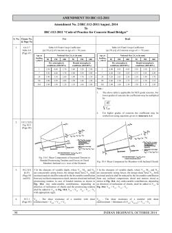
© Copyright 2026