
, Croatian, Pages 503
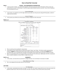
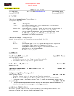
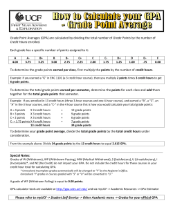
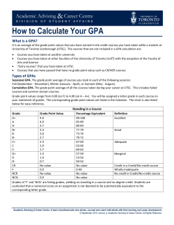
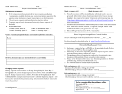
K. Rokosz i dr. ANSYS analiza naprezanja i deformacije nakon plastične deformacije konusa ISSN 1330-3651 (Print), ISSN 1848-6339 (Online) DOI: 10.17559/TV-20140211104533 ANSYS ANALYSIS OF STRESS AND STRAIN AFTER CONES PLASTIC DEFORMATION Krzysztof Rokosz, Tadeusz Hryniewicz, Winfried Malorny, Jan Valiček, Marta Harničárová Preliminary notes The paper deals with study of stress and strain after cones plastic deformation by ANSYS software. There are shown the new results of FEM analysis, what is the base for the further experimental studies. Keywords: ANSYS analysis; carbon steel C45; cones shape; plastic deformation ANSYS analiza naprezanja i deformacije nakon plastične deformacije konusa Prethodno priopćenje Rad se bavi proučavanjem naprezanja i deformacija nakon plastične deformacije konusa pomoću ANSYS softvera. Prikazani su novi rezultati FEM analize, što je osnova za daljnje eksperimentalne studije. Ključne riječi: ANSYS analiza; konični oblik; plastična deformacija; ugljični čelik C45 1 Introduction Numerical analysis of non-linear plastic deformation especially by rolling [1 ÷ 6] with the appointment of team working on stress and strain analysis [7 ÷ 12] was studied. It was also possible to find a solution of contact problem of movable elasto/visco-plastic body [8] and thermal numerical analysis in deformation zone [9, 10] as well as mathematical modelling of deformation of the asperity in the burnishing rolling operation [11]. Based on the available literature on the theory of solid mechanics and finite-element method [14, 15, 16] the authors proposed in this paper the cone deformation analysis using a simulation experiment in ANSYS. The simulation analysis presented below will be performed in the future as experiment using a strain-stress machine. Then, during these measurements, the additional analyses such as noncontact methods of surface analysis [17], measurements uncertainties [18], etc., will be performed. Moreover there is planned a comparison of the stress and strain results after cold rolling of flat plates [18] with other ones concerning e.g. triangle and/or trapezoidal cross sections. Deformation is characterized by the change in mutual displacement of points on the solid surface due to the action of applied loads. There is an elastic deformation which vanishes just after removal of the load, as well as the plastic/firm deformation which remains after load removal. The deformation state is characterized by linear and angular deformations (Fig. 1). The linear deformation occurs e.g. during extending the rod of a uniform square cross-section due to a normal stress (Fig. 1a). If the deformation is determined from the dependence: ε= lc − l0 , l0 (1) where: l0 and lc – initial and transient/temporary rod length so they are determined as relative/apparent deformations. Tehnički vjesnik 22, 2(2015), 503-508 Figure 1 Deformation schematics: a) one-axis extension and compression, b) hydrostatic compression [13] In practice, the relative deformations are usually given in per cent: ε= lc − l0 100, %. l0 The deformation ε is an apparent characteristic because while it’s determining no continuous change in the rod length is regarded during the deformation. The real deformation εrz, called the logarithmic deformation, in the opposition to the relative deformation ε, reflects the physical meaning of deformation. It may be confirmed basing on the following example: if during the extension the initial length of rod l0 is increased up to 2l0, and during compressing l0/2, the relative deformations are equal in both cases as to the value and opponent/adverse as to the sign. In such conditions under extension: ε= 2l0 − l0 = 1, l0 503 ANSYS analysis of stress and strain after cones plastic deformation ε rz = ln K. Rokosz et al. 2l0 = ln 2 = 0 ,69, l0 and under compression: l0 − l0 = −0 ,5, , ε= 2 l0 ε rz l0 1 = ln 2 = ln = ln 1 − ln 2 = −ln 2 = −0 ,69. l0 2 Figure 2 Schemes of stress determination in the point of coordination system: a) x1, x2, x3; b) x, y, z [13] Evaluation/estimation of the deformation state in any point of the body relies on determination of the length change between the point and any other neighbouring point and the change of angle between two directions coming out of the same point, occurring as the result of deformation. Relative deformations in the directions x1 and x2 are described by the equations: (u1 + ∂u1 ∂u dx1 ) − u1 (u 2 + 2 dx1 ) − u 2 ∂x1 ∂u1 ∂u ∂x1 = , = 2. ∂x1 dx1 ∂x1 dx1 Under introducing the third axis x3 there will be the third relative deformation ∂u3/∂x1. Additionally, there are two angular deformations ∂u1/∂x2 and ∂u1/∂x3, ∂u2/∂x2 and ∂u2/∂x3 as well as ∂u3/∂x2 and ∂u3/∂x3 against each of the three axes. These deformations form a tensor of relative deformations [14, 15, 16]: ∂u1 ∂x1 ∂u ∂u 2 = ∂x ∂x1 ∂u3 ∂x1 ∂u1 ∂x2 ∂u 2 ∂x2 ∂u3 ∂x2 ∂u1 ∂x3 e11 e12 ∂u 2 or eij = e21 e22 ∂x3 e31 e32 ∂u3 ∂x3 σ xx τ xy Tij = τ yx σ yy τ zx τ zy τ xz σ 11 σ 12 σ 13 τ yz , σ ij = σ 21 σ 22 σ 23 , σ 31 σ 32 σ 33 σ zz where: σij for i = j (e.g. σxx, σ22) – normal stresses, σij for i ≠ j (e.g. σxz, σ31) – tangent stresses. Conditions of equilibrium of a body require the summary rotary moment against each of the three coordination axes to be zero. From this, the rule of pairs of tangent stresses results: the symmetric components against the general diagonal of tensor must possess simultaneously identical in pairs absolute values with their turns directed to the common edge or from it (τ21 = τ12, τ31 = τ13, τ32 = τ23). Inequality τij = τji means arising of a rotary moment against the axis x3 (Fig. 3). e13 e23 . e33 Values and types of stresses depend first of all on the processes of deformations and cracking. In the studies of mechanical properties the characteristics of the stress state in each point of the body are necessary. The values of stresses existing in each cross-section coming through the point should be known. Taking into consideration the whole body volume one may separate just a tiny parallelepiped with the edges forming rectangular coordination system of axes marked as x, y, z or x1, x2, x3 (Fig. 2). In a general case, the mutually balanced stresses which may be easily distributed onto one normal and two tangent components, act on its three non-parallel faces. Each component is marked by two indexes. The first index of the stress denotes the plane on which the stress acts (x, y, z or 1, 2, 3), and corresponds with the index of axis perpendicular to this plane, the second one denotes the direction of stress action (x, y, z or 1, 2, 3). All the occurring components of stress (3 normal and 6 tangent) acting in the faces of elementary parallelepiped fully determine the stress state in any point. 504 They may be presented in the form of matrix, called the stress tensor: Figure 3 Scheme of positioning of tangent components of stress τ12 and τ21 [13] This rule has the essential meaning in formulating conditions of equilibrium of a solid in the studies of mechanical properties (stress state) because the processes with the tangent stresses occur in two groups of the mutually perpendicular planes. The studies of stress state rely mainly on the determination of normal stresses because they are used in calculations of design strength. It results from the theory of elasticity and plasticity that one may draw three mutually perpendicular planes through each of the solid point being under the state of stresses; they are called the general planes in which the normal stresses attain the extremum values (σmax, σmin), with no tangent stresses occurring. Axes of the Technical Gazette 22, 2(2015), 503-508 K. Rokosz i dr. ANSYS analiza naprezanja i deformacije nakon plastične deformacije konusa coordination system determined by straight/lines of intersections of these planes are the general directions and the stresses acting in the direction of these axes are called the general stresses (σ11, σ22, σ33). They are denoted usually in a simpler manner: σ11 → σ1, σ22 → σ2, σ33 → σ3. In the mechanical studies the general directions are known, e.g. under axial tension, pressing ball into the material surface during the hardness measurement; they may be assumed as the coordination axes. Taking into account the general coordinates, the tensor of stresses is simplified and takes the form: ANSYS meshed sample of cone is shown in Fig. 4 and the parameters and properties of ANSYS model of the studied C45 steel are demonstrated in Tab. 1. 0 σ 1 0 σ = 0 σ 2 0 , 0 0 σ 3 with σ1> σ2> σ3. The highest tangent stresses occur in the planes situated at the angle 45° to the general directions and their value is equal to the half of difference of the respective main stresses: τ1 = σ2 −σ3 σ −σ3 σ −σ2 , τ2 = 1 , τ3 = 1 . 2 2 2 If the main stresses σ1, σ2 or σ3 are equal: σ1 = σ2 = σ3, so the tangent stresses τ1 = τ2 = τ3 = 0. The stresses in any occurring cross-section, coming through the marked point of a body, may be determined by the main stresses and the directional cosinuses of the cross-section, i.e. the cosinuses of angles existing between a normal n to the cross-section plane and the respective coordinate axes: cos ∠(n, x) = f x , cos ∠(n, y ) = f y , cos ∠(n, z ) = f z , with ∠ meaning angle, then the normal and tangent stresses are determined by the dependences: Figure 4 Meshed sample of cone deformation in ANSYS [13] Table 1 Parameters and properties of the studied C45 steel for CooperSymonds material model [13] Parameters and properties of the steel Density ρ / kg/m3 Young’s modulus E / GPa Poisson’s ratio ν / – Strengthening parameter β / – Yield stress σ0 / MPa Material parameter depending the plastic strain hardening Etan / MPa Material parameter defining the effect of intensity of plastic strain rate C / 1/s Material constatnt defining the material's sensitivity to plastic strain rate P / – Failure strain / – Steel C45 7865 200 0.29 1 342 241 5 10 0,75 The ANSYS simulations were performed based on the five-level rotatable plan of experiment that is shown in Tab. 2. Table 2 Five-level rotatable plan of experiment based on [12] σ = f x2σ 1 + f y2σ 2 + f z2σ 3 , ( ) 1 2 τ = f x2σ 1 + f y2σ 2 + f z2σ 3 − f x2σ 1 + f y2σ 2 + f z2σ 3 2 . The stress state in a point may be characterized by six independent parameters: three normal stresses and three tangent stresses, or three normal stresses and three directional cosinuses. The stress state, in which three main stresses act, is called a spatial, volumetric, or threedimensional state. The stress state in which only two main stresses act (the third one is equal to zero) is called a flat or two-dimensional state. In linear or one-dimensional state of stresses the only one, general stress is different from zero. 2 Materials and method Carbon SteelC45 (JUSČ.1530, DIN C45, BS 080M46, GOST 45 AISI 1043, NF AF65C45, UNI C45) is the most popular material used in the industry. The Tehnički vjesnik 22, 2(2015), 503-508 505 ANSYS analysis of stress and strain after cones plastic deformation 3 Results and discussion The shapes and deformations of cones as well as stress and strain are shown in Figs. 5, 6, 7, and 8. Maximum intensity of stresses for 10 % strain of cone of the top angle 60° equals σmax = 0,604 GPa, whereas the minimum stress σmin = 0,023 GPa. The substitute stresses were as follows: σzmax = 0,573 GPa and σzmin = 0,02 GPa, respectively. The first degree stresses for 10 % strain equal σ1 = 4,33 GPa, the second degree stresses equal σ2 = 4,23 GPa, whereas the third degree stresses equal σ3 = 4,01 GPa. Deformations are equal to ε = 1,754, and the substitute deformations εz = 1,677. Maximum intensity of stresses for 30 % strain of sample of the top angle 60° equals σmax = 0,587 GPa, whereas the minimum intensity of stress σmin = 0,186 GPa. Maximum substitute stresses for the studied sample were σzmax = 0,558 GPa, and minimum substitute stresses σzmin = 0,177 GPa. The first degree stresses for 30 % strain equal σ1 = 3,42 GPa, whereas the second degree stresses are equal to σ2 = 3,35 GPa, and the third degree stresses equal σ3 = 2,87 GPa. Deformations values are ε = 1,906, and the substitute deformations εz = 1,721 (Fig. 6). K. Rokosz et al. the studied sample were σzmax = 0.482 GPa and the minimum substitute stresses σzmin = 0,098 GPa. The first degree stresses for 30 % strain equal σ1 = 1,29 GPa, whereas the second degree stresses are equal to σ2 = 1,23 GPa, and the third degree stresses equal σ3 = 0,833 GPa. For the crush attempt the intensity of deformations equals ε = 1,128, and the substitute deformations equal εz =1,002. Figure 6 Results of stress and deformation intensity of cones of top angle 60°, with the flat punch and 10 %, 30 %, and 50 % strains [13] Figure5 Shapes and deformations of cones of top angle: (A) 60°, (B) 90°, (C) 120° [13] Maximum intensity of stresses for 50 % strain of sample of the top angle 60° equals σmax = 0,586 GPa, whereas the minimum intensity of stress σmin = 0,200 GPa. Maximum substitute stresses for the studied sample were σzmax = 0,561 GPa, and minimum substitute stresses σzmin = 0,177 GPa. The first degree stresses for 50 % strain equal σ1 = 3,63 GPa, whereas the second degree stresses are equal to σ2= 3,59 GPa, and the third degree stresses equal σ3 = 2,87. The result of maximum intensity of stresses for 10 % strain of cone of the top angle 90° equals σmax = 0,467 GPa, whereas the minimum intensity of stresses σmin = 0,018 GPa. The substitute maximum stresses for the studied sample were σzmax = 0,451 GPa and the minimum substitute stresses σzmin = 0,015 GPa. The first degree stresses for 10 % strain equal σ1 = 2,94 GPa, whereas the second degree stresses are equal to σ2 = 2,92 GPa, and the third degree stresses equal σ3 = 2,72 GPa. The intensity of deformations equals ε = 1,113, and the substitute deformations equal εz = 0,99. The result of maximum intensity of stresses for 30 % strain of cone of the top angle 90° equals σmax = 0,527 GPa, whereas the minimum intensity of stresses σmin = 0,112 GPa. The substitute maximum stresses for 506 Figure 7 Results of stress and deformation intensity of cones of top angle 90°, with the flat punch and 10 %, 30 %, and 50 % strains [13] The result of maximum intensity of stresses for 50 % strain of cone of the top angle 90° equals σmax = 0,517 GPa, whereas the minimum intensity of stresses σmin = 0,133 GPa. The substitute maximum stresses for the studied sample were σzmax = 0,459 GPa and the minimum substitute stresses σzmin = 0,124 GPa. The first degree stresses for 50 % strain equal σ1 = 0,928 GPa, Technical Gazette 22, 2(2015), 503-508 K. Rokosz i dr. whereas the second degree stresses are equal to σ2 = 0,896 GPa, and the third degree stresses equal σ3 = 0,478 GPa. The intensity of deformations for the studied sample equals ε = 1,128, and the substitute deformations equal εz = 1,026 (Fig. 7). ANSYS analiza naprezanja i deformacije nakon plastične deformacije konusa GPa, and the third degree stresses equal σ3 = 0,378 GPa. The cone crush experiment shows that the intensity of deformations equals ε = 0,795, and the substitute deformations equal εz = 0,704. The complete results ordered by the five-level rotatable statistical plan are given in Tab. 3. Fig. 9 shows the plane graph with mathematical formula which described about 87 % of the points obtained by ANSYS simulation (Tab. 3). Based on this data processing there was noticed that under the cone deformation the top angle has a significant effect on the stress and strain in the deformed surface layer. It was found that at the top angle of 120° and at 50 % deformation the highest stress was obtained. Table 3 Five-level rotatable plan of experiment based on [12] Figure 8 Results of stress and deformation intensity of cones of top angle 120°, with the flat punch and 10 %, 30 %, and 50 % strains [13] The result of maximum intensity of stresses for 10 % strain of cone of the top angle 120° equals σmax = 0,457 GPa, whereas the minimum intensity of stresses σmin = 0,017 GPa. The substitute maximum stresses for the studied sample were σzmax = 0,432 GPa and the minimum substitute stresses σzmin = 0,016 GPa. The first degree stresses for 10 % strain equal σ1 = 0,769 GPa, whereas the second degree stresses are equal to σ2 = 0,612 GPa, and the third degree stresses equal σ3 = 0,466 GPa. The cone crush experiment shows that the intensity of deformations equals ε = 0,716, and the substitute deformations equal εz = 0,701. The result of maximum intensity of stresses for 30 % strain of cone of the top angle 120° equals σmax = 0,493 GPa, whereas the minimum intensity of stresses σmin = 0,214 GPa. The substitute maximum stresses for the studied sample were σzmax = 0,442 GPa and the minimum substitute stresses σzmin = 0,203 GPa. The results of first, second, and third degrees of stresses have been shown in Figs. 2, 3,4. The first degree stresses for 30 % strain equal σ1 = 1,50 GPa, whereas the second degree stresses are equal to σ2 = 1,44 GPa, and the third degree stresses equal σ3 = 1,10 GPa. The cone crush experiment shows that the intensity of deformations equals ε = 0,738, and the substitute deformations equal εz = 0,759. The maximum intensity of stresses for 50 % strain of cone of the top angle 120° equals σmax = 0,509 GPa, whereas the minimum intensity of stresses σmin = 0,126 GPa. The substitute maximum stresses for the studied sample were σzmax = 0,457 GPa and the minimum substitute stresses σzmin = 0,110 GPa. The first degree stresses for 50% strain equal σ1 = 0,688 GPa, whereas the second degree stresses are equal to σ2 = 0,564 Tehnički vjesnik 22, 2(2015), 503-508 S = exp(–1,075 + 0,0003·α + 0,0041·d), R2=0,87 where: S – stress, α – angle, d – deformation Figure 9 3D plot of influence of the deformation on stress 4 Conclusion The following conclusions may be formulated after the studies: • Under the cone deformation, the top angle has a significant effect on the strain in the deformed surface layer • Under the cone deformation, the top angle has a significant effect on the stress in the deformed surface layer • The highest stress was obtained at the top angle 120° and at 50 % deformation. Acknowledgment Experiments were carried out partly by DAADForschungsaufenthalt für Hochschullehrer und Wissenschaftler (DAAD research stays for University Academics and Scientists). This paper has been 507 ANSYS analysis of stress and strain after cones plastic deformation elaborated in the framework of the Moravian-Silesian Region project no. RRC/01569/2012 and the project RMTVC no. CZ.1.05/2.1.00/01.0040. Thanks also go to the IT4Innovations Centre of Excellence project, reg. no. CZ.1.05/1.1.00/02.0070. 5 References [1] Kułakowska, A.; Kukiełka, L. Numerical analysis and experimental researches of burnishing rolling process with taking into account deviations in the surface asperities outline after previous treatment. / 12th International Conference on Metal Forming, Cracow, Poland. // Steel Research International. 2008, pp. 42-48. [2] Patyk, R.; Kukiełka, L. Optimization of geometrical parameters of regular triangular asperities of surfaces put to smooth burnishing. / 12th International Conference on Metal Forming, Cracow, Poland. // Steel Research International. 2008, pp. 642-647. [3] Kukiełka, L.; Chodor, J.; Storch, B. New method of determination of the tool rake angle on the basis of the crack angle of the specimen in tensile tests and numerical simulations. / 9th International Conference on Surface Effects and Contract Mechanics, Algarve, Portugal. Surface Effects and Contact Mechanics, IX Book Series: // WIT Transactions on Engineering Sciences. 2009, pp. 207-216. [4] Kukiełka, L.; Kukiełka, K. Numerical analysis of the physical phenomena in the working zone in the rolling process of the round thread. // Transactions on Engineering Sciences. 55, (2007), pp. 125-134. DOI: 10.2495/SECM070121 [5] Kukiełka, L.; Chodor, J. Numerical analysis of the influence of abrasive grain geometry and cutting angle on states of strain and stress in the surface layer of object. // Transactions on Engineering Sciences. 55, (2007), 183193. DOI: 10.2495/SECM070181 [6] Kukiełka, L.; Kukiełka, K. Numerical analysis of the process of trapezoidal thread rolling. // Transactions on the Built Environment. 85, (2006), pp. 663-672. DOI: 10.2495/HPSM06065 [7] Kukiełka, L.; Kustra, J.; Kukiełka, K. Numerical analysis of states of strain and stress of material during machining with a single abrasive grain. / 7th International Conference on Computer Methods and Experimental Measurements for Surface Effects and Contact Mechanics, Bologna, Italy. // Transactions on Engineering Sciences. 49, (2005), pp. 5766. [8] Kukiełka, L. Numerical modeling: the contact problem of movable elasto/visco-plastic body. // 6th International Conference on Computational Methods in Contact Mechanics, Iraklion, Greece. Computational and Experimental Methods. 8, (2003), pp. 93-102. [9] Kukiełka, L.; Kustra, J. Numerical analysis of thermal phenomena and deformations in processing zone in the centerless continuous grinding process. // 6th International Conference on Computational Methods in Contact Mechanics, Iraklion, Greece. Computational and Experimental Methods. 7, (2003), pp. 109-118. [10] Kukiełka, L. Non-linear analysis of heat transfer in burnishing rolling operation. // 7th International Conference on Advanced Computational Methods in Heat Transfer, Halkidiki, Greece. Computational Studies. 4, (2002), pp. 405-414. [11] Kukiełka, L. Mathematical modelling and numerical simulation of non-linear deformation of the asperity in the burnishing cold rolling operation. / 5th International Conference on Computational Methods in ContactMechanics, Sevilla, Spain. // Computational and Experimental Methods. 5, (2001), pp. 317-326. 508 K. Rokosz et al. [12] Kukiełka, L. Fundamentals of Engineering Studies (Podstawy badań inżynierskich), Publisher: PWN, 2002, ISBN: 83-01-13749-5. [13] Rypina, Ł. Analiza wpływu zgniotu stożka na odporność korozyjną powierzchni po deformacji, Master’sThesis, Faculty of Mechanical Engineering, Koszalin University of Technology, 2007. [14] Kleiber, M. Metoda elementów skończonych w nieliniowej mechanice kontinuum, Biblioteka Mechaniki Stosowanej Instytut Podstawowych Problemów Techniki PAN, PWN, Warszawa-Poznań 1985. ISBN: 83-01-05051-9. [15] Ostrowska-Maciejewska, J. Mechanika Ciał Odkształcalnych, PWN, Warszawa, 1994. [16] Fung, Y. C. Podstawy Mechaniki Ciała Stałego, PWN, Warszawa 1969, ISBN: 83-01-11415-0. [17] Valiček, J.; Drzik, M.; Hryniewicz, T.; Harničarova, M.; Rokosz, K.; Kusnerova, M.; Barcova, K.; Brazina, D. Noncontact method for surface roughness measurement after machining. // Measurement Science Review. 12, 5(2012), pp. 184-188. DOI: 10.2478/v10048-012-0028-3 [18] Kusnerova, M.; Valiček, J.; Harničarova, M.; Hryniewicz, T.; Rokosz, K.; Palkova, Z.; Vaclavik, V.; Repka, M.; Bendova, M. A proposal for simplifying the method of evaluation of uncertainties in measurement results. // Measurement Science Review. 13, 1(2013), pp. 1-6. DOI: 10.2478/msr-2013-0007 [19] Szarkova, V.; Valiček, J.; Vlado, M.; Harničarova, M.; Rokosz, K.; Luptak, M.; Samardzic, I.; Kozak, D.; Hloch, S. Influence of longitudinal cold rolling on the surface topography of low carbon structural steel. // Tehnicki vjesnik-Technical Gazette. 20, 4(2013), pp. 705-709. Authors' addresses Krzysztof Rokosz Tadeusz Hryniewicz (corresponding author) Division of Surface Electrochemistry and Engineering Faculty of Mechanical Engineering, Koszalin University of Technology Racławicka 15-17, PL 75-620 Koszalin, Poland E-mail: [email protected] E-mail: [email protected] Winfried Malorny Baustoffkunde, Bautenschutz/Sanierungsbaustoffe, Bauphysik Bereich Bauingenieurwesen, Hochschule Wismar Philip-Müller-Straße 14, DE 23966 Wismar, Germany E-mail: [email protected] Jan Valiček Marta Harničárová Institute of Physics, Nanotechnology Centre, VŠB - Technical University of Ostrava, 17. listopadu 15/2172, 708 33 Ostrava-Poruba, Czech Republic E-mail: [email protected] E-mail: [email protected] Technical Gazette 22, 2(2015), 503-508


© Copyright 2026