
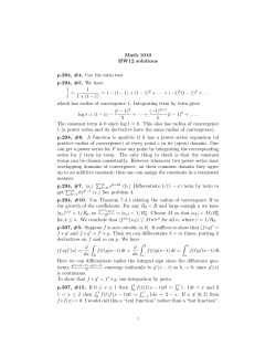
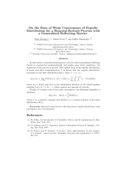
Strictly single-site DMRG algorithm with subspace expansion
PHYSICAL REVIEW B 91, 155115 (2015)
Strictly single-site DMRG algorithm with subspace expansion
C. Hubig,1,* I. P. McCulloch,2 U. Schollw¨ock,1 and F. A. Wolf1
1
Department of Physics and Arnold Sommerfeld Center for Theoretical Physics, Ludwig-Maximilians-Universit¨at M¨unchen,
Theresienstrasse 37, 80333 M¨unchen, Germany
2
Centre for Engineered Quantum Systems, School of Physical Sciences, The University of Queensland, Brisbane, Queensland 4072, Australia
(Received 26 January 2015; revised manuscript received 26 March 2015; published 10 April 2015)
We introduce a strictly single-site DMRG algorithm based on the subspace expansion of the alternating minimal
energy (AMEn) method. The proposed new MPS basis enrichment method is sufficient to avoid local minima
during the optimization, similar to the density matrix perturbation method, but computationally cheaper. Each
application of Hˆ to | in the central eigensolver is reduced in cost for a speed-up of ≈ (d + 1)/2, with d
the physical site dimension. Further speed-ups result from cheaper auxiliary calculations and an often greatly
improved convergence behavior. Runtime to convergence improves by up to a factor of 2.5 on the Fermi-Hubbard
model compared to the previous single-site method and by up to a factor of 3.9 compared to two-site DMRG.
The method is compatible with real-space parallelization and non-Abelian symmetries.
DOI: 10.1103/PhysRevB.91.155115
PACS number(s): 05.10.Cc, 02.70.−c, 71.27.+a
I. INTRODUCTION
Since its introduction in 1993 [1,2], the density matrix
renormalization group method (DMRG) has seen tremendous
use in the study of one-dimensional systems [3,4]. Various
improvements such as real-space parallelization [5], the use
of Abelian and non-Abelian symmetries [6], and multigrid
methods [7] have been proposed. Most markedly, the introduction [8] of density matrix perturbation steps allowed the
switch from two-site DMRG to single-site DMRG in 2005,
which provided a major speed-up and improved convergence
in particular for systems with long-range interactions.
Nevertheless, despite some progress [9–11], (nearly) twodimensional systems, such as long cylinders, are still a hard
problem for DMRG. The main reason for this is the different
scaling of entanglement due to the area law [12,13]: in one
dimension, entanglement and hence matrix dimensions in
DMRG are essentially size-independent for ground states of
gapped systems, whereas in two dimensions, entanglement
grows linearly and matrix dimensions roughly exponentially
with system width.
As a result, the part of the Hilbert space considered by
DMRG during its ground state search increases dramatically,
resulting mainly in three problems as follows. First, the
DMRG algorithm becomes numerically more challenging
as the sizes of matrices involved grow [we will assume
matrix-matrix multiplications to scale as O(m3 ) throughout
the paper]. Second, the increased search space size makes
it more likely to get stuck in local minima. Third, while
sequential updates work well in one-dimensional (1D) chains
with short-range interactions, nearest-neighbor sites in the 2D
lattice can be separated much farther in the DMRG chain.
Therefore, improvements to the core DMRG algorithm are
still highly worthwhile.
In this paper, we will adopt parts of the AMEn method [14]
developed in the tensor train/numerical linear algebra community to construct a strictly single-site DMRG algorithm
that works without accessing the (full) reduced density
*
[email protected]
1098-0121/2015/91(15)/155115(10)
matrix. Compared to the existing center matrix wave function
formalism (CWF) [15], we achieve a speed-up of ≈ (d + 1)/2
during each application of Hˆ to | in the eigensolver during
the central optimization routine, where d is the dimension of
the physical state space on each site.
The layout of this paper is as follows. Section II will
establish the notation. Section III will recapitulate the density
matrix perturbation method and the CWF. Section IV will
introduce the subspace expansion method and the heuristic
expansion term with a simple two-spin example. The strictly
single-site DMRG algorithm (DMRG3S) will be presented in
Sec. V alongside a comparison with the existing CWF. As both
the original perturbation method and the heuristic subspace
expansion require a mixing factor α [8], Sec. VI describes
how to adaptively choose α for fastest convergence. Numerical
comparisons and examples will be given in Sec. VII.
II. DMRG BASICS
The notation established here closely follows the review
article in Ref. [4]. Consider a state | of a system of l sites.
Each site has a physical state dimension di , e.g., ∀i : di = 3,
l = 50 for a system of 50 S = 1 spins:
| =
cσ1 ...σl |σ1 . . . σl .
(1)
σ1 ...σl
In practice, the dimension of the physical basis is usually
constant, ∀i : di = d, but we will keep the subscript to refer to
one specific basis on site i where necessary.
It is then possible to decompose the coefficients cσ1 ,...,σl as
a series of rank-3 tensors M1 , . . . ,Ml of size (di ,mi−1 ,mi ),
respectively, with m0 = ml = 1. The coefficient cσ1 ,...,σl can
then be written as the matrix product of the corresponding
matrices in M1 , . . . ,Ml :
σ
M1 1 · · · Mlσl |σ1 . . . σl .
(2)
| =
σ ...σ
1
l
cσ1 ...σl
The maximal dimension m = maxi {mi } is called the MPS
bond dimension. In typical one-dimensional calculations,
m = 200, but for, e.g., 32 × 5 cylinders, m > 5000 is often
155115-1
©2015 American Physical Society
¨
HUBIG, MCCULLOCH, SCHOLLWOCK,
AND WOLF
PHYSICAL REVIEW B 91, 155115 (2015)
necessary. It is in these numerically demanding cases that our
improvements are of particular relevance.
Similarly, a Hamiltonian operator can be written as a matrix
product operator (MPO), where each tensor Wi is now of rank
4, namely (di ,di ,wi−1 ,wi ):
Hˆ =
W1σ1 τ1 · · · Wlσl τl |σ1 . . . σl τ1 . . . τl |.
(3)
σ 1 . . . σl
τ1 . . . τl
w = maxi {wi } is called the MPO bond dimension. We will
usually assume that for most i, mi = m and wi = w. In
practice, this holds nearly everywhere except at the ends of the
chain, where the mi grow exponentially from 1 to m. The basis
of Mi (Wi ) of dimension mi−1 (wi−1 ) is called the left-hand
side (LHS) basis, whereas the basis of dimension mi (wi ) is
the right-hand side (RHS) basis of this tensor. For simplicity,
mi , di , and wi can also refer to the specific basis (and not only
its dimension) when unambiguous.
Instead of Mi , we will also write Ai (Bi ) for a left (right)
normalized MPS tensor:
σ† σ
Ai i Ai i = I,
(4)
σi
σ†
Biσi Bi i = I.
(5)
σi
If we then define the contractions
σi−1
li = Aσ11 · · · Ai−1
Miσi ∈ (d1 , . . . ,di ,mi ),
σi+1
ri = Miσi Bi+1
· · · Blσl ∈ (mi−1 ,di , . . . ,dl ),
we can rewrite | from (2) as
| =
li ri+1 |σ1 . . . σi ⊗ |σi+1 . . . σl .
(6)
A. Convergence problems of single-site DMRG
During single-site DMRG, only a single MPS tensor Mi on
site i is optimized at once. Compared to two-site DMRG, the
search space is reduced by a factor of d ≈ 2 . . . 5, leading to
a speed-up of at least O(d) per iteration [8]. However, since
the left and right bases of the tensors Mi are fixed and defined
by the environment (li−1 and ri+1 ), this approach is likely to
get stuck. While also occurring if there are no symmetries
implemented on the level of the MPS, this issue is most easily
visible if one considers U (1) symmetries [4]: assume that all
basis states to the right of the RHS bond of Mi transform as
some quantum number sz . If we now target a specific sector,
e.g., Sz = 0 overall, then on the LHS of this bond (i.e., from
the left edge up to and including Mi ), all states must transform
as −sz . In this configuration, it is impossible for a local change
of Mi to add a new state that transforms as, say, sz , to its right
basis states, as there would be no corresponding state −sz to
the right of that bond, rendering the addition of the state moot
from the perspective of the local optimizer, as its norm will be
zero identically. A concrete example of this issue is given in
Sec. VII A.
DMRG is a variational approach on the state space available
to MPS of a given bond dimension. As such, the algorithm
must converge into either the global or a local minimum of
the energy in this state space. Hence, we will call all cases
where DMRG converges on an energy substantially higher
than the minimal energy achievable with the allowed MPS
bond dimension cases where DMRG is stuck in local minima.
(7)
B. Density matrix perturbation
(8)
σ1 ...σl
That is, when only considering one specific bond (i,i + 1), the
left and right MPS bases at this bond are built up from the
states generated by the MPS tensor chains to the left and right
of the bond. Individual elements of an MPS basis are therefore
called “state.”
†
Furthermore, define L0 = 1 and Li = Li−1 Ai Wi Ai with
summation over all possible indices. Similarly, Rl+1 = 1 and
†
Ri = Ri+1 Bi Wi Bi . With these contractions, it is possible to
write
†
|Hˆ | = Li−1 Mi Wi Mi Ri+1
III. PERTURBATION STEP AND CENTER MATRIX WAVE
FUNCTION FORMALISM (CWF)
(9)
for any i ∈ [0,l].
DMRG then works by sweeping over the system multiple
times. During each sweep, each site tensor Mi is sequentially
updated once with each update consisting of one optimization
step via, e.g., a sparse eigensolver and possibly one enrichment
step during which the left or right MPS basis of Mi is changed
in some way. Depending on the exact implementation, updates
may work on one (single-site DMRG) or two sites (two-site
DMRG) at a time. The enrichment step may be missing
or implemented via density matrix perturbation or subspace
expansion.
This convergence problem has been solved by White [8]. In
the following, we will assume a left-to-right sweep; sweeping
in the other direction works similarly, but on the left rather
than right bonds. After the local optimization of the tensor Mi ,
the reduced density matrix
† †
ρi,R = li−1 Mi Mi li−1
(10)
is built on the next bond. This is the reduced density matrix
resulting from tracing out the part of the system to the left of
bond (i,i + 1).
ρi,R is then perturbed as
†
ρi,R → ρi,R
= ρi,R + α Tr(Li ρi,R Li ).
(11)
ρi,R
The new
is then used to decide on a new set of basis
states on the RHS of Mi , with the inverse mapping from the
new to the old basis being multiplied into each component of
Bi+1 . The mixing factor α is a small scalar used to control the
perturbation. A new scheme to find the optimal choice of α is
discussed in Sec. VI.
C. Center matrix wave function formalism (CWF)
In a standard single-site DMRG calculation, the reduced
density matrix ρi,R is never used. More importantly, even
building ρi,R on a given bond (i,i + 1) will not yield a density
matrix that can be used in (11), as it only contains the mi states
155115-2
STRICTLY SINGLE-SITE DMRG ALGORITHM WITH . . .
PHYSICAL REVIEW B 91, 155115 (2015)
existing on that bond already without knowledge of the mi−1
states on the bond one step to the left. In other words, it is not
possible to choose the optimal set m
i based only on mi ; rather,
one requires also di and mi−1 .
The center matrix wave function formalism [15] was
developed to cope with this problem. Given a site tensor
Mi ∈ (di ,mi−1 ,mi ) on a left-to-right sweep, it introduces a
“center matrix” Ci,R ∈ (di mi−1 ,mi ) and replaces the original
site tensor as
Mi → Ai ∈ (di ,mi−1 ,di mi−1 ) so that Mi = Ai Ci,R .
(12)
Ai is constructed to be left orthogonal and is essentially an
identity matrix mapping the left basis mi−1 and the physical
basis di onto a complete basis containing all di mi−1 states on
its right. The new basis is “complete” in the sense that all states
reachable from the left bond basis mi−1 and the local physical
basis di are contained within it.
The contents of Mi are placed in Ci,R accordingly and the
original state remains unchanged. The reduced density matrix
†
is then ρi,R = Ci,R Ci,R and has access to all di mi−1 states, as
required above. A perturbation of ρi,R according to (11) hence
allows the introduction of new states.
The DMRG optimization step can work on Ci,R alone, with
Li built prior to optimization of Ci,R from the expanded Ai .
During each eigensolver step, the effective Hamiltonian on
site i has to be applied onto Ci,R . The application is done by
contraction of Li ∈ (w,di mi−1 ,di mi−1 ), Ri+1 ∈ (w,mi ,mi ),
and Ci,R ∈ (di mi−1 ,mi ) at cost O(w(d 2 + d)m3 ) per step.
After optimization, the perturbation is added. Its computa†
tional cost is dominated by the calculation of α Tr{Li ρi,R Li }
3 3
at O(wd m ). The bond between Ai and Ci,R can then be
and the remaining parts of
truncated down to m using ρi,R
Ci,R are multiplied into Bi+1 to the right.
The resulting algorithm converges quickly for onedimensional problems and performs reasonably well for small
cylinders. However, both the cost of the applications of Hˆ to
| as O(w(d 2 + d)m3 ) as well as the large density matrix
ρ ∈ (dm,dm) cause problems if m and w become large.
IV. SUBSPACE EXPANSION
The idea of using subspace expansion instead of density matrix perturbation originates [14,16] in the tensor
train/numerical linear algebra community. There, a stringent
proof was given regarding the convergence properties of this
method when the local tensor Zi of the residual
|Z ≡ Hˆ | − E| =
Z1σ1 · · · Zlσl |σ1 . . . σl (13)
σ1 ...σl
is used as the expansion term. Here, we will only use the
method of subspace expansion and substitute a numerically
much more cheaply available expansion term.
The following section is divided into three parts as follows.
First, we will explain the concept of subspace expansion
acting on two neighboring MPS tensors Mi , Mi+1 . Second,
the expansion term employed in DMRG3S is introduced and
motivated. Third, a simple example is described.
A. Subspace expansion with an arbitrary expansion term
In the following, we will describe subspace expansion of
the RHS basis of the current working tensor, as it would occur
during a left-to-right sweep.
Assume a state | described by a set of tensors
{A1 , . . . ,Ai−1 ,Mi ,Bi+1 , . . . ,Bl }. At the bond (i,i + 1), we can
then decompose the state as a sum over left and right basis
states as in Eq. (8).
Now we expand the tensor Mi ∈ (d,mi−1 ,mi ) by some expansion term Pi ∈ (d,mi−1 ,mPi ) for each individual physical
index component:
σ
σ (14)
Miσi → M˜ iσi = Mi i Pi i .
This effectively expands the RHS MPS basis of Mi from
mi to mi + mPi . Similarly, expand the components of Bi+1 ∈
(d,mi ,mi+1 ) with zeros:
σi+1 Bi+1
σi+1
σi+1
.
(15)
Bi+1
→ B˜ i+1
=
0
The appropriately sized block of zeros only multiplies with
the expansion term Piσi . In terms of a decomposition as in (8),
this is equivalent to
r
[li p] i+1 |σ1 . . . σi ⊗ |σi+1 , . . . ,σl (16)
| =
0
σ1 ,...,σl
where p is the result of multiplying li−1 and Pi , with the
zero in the second expression similarly resulting from the zero
in Bi+1 . While the state | remains unchanged, the local
optimizer on the new site Bi+1 can now choose the initially zero
components differently if so required: the necessary flexibility
in the left/right basis states to escape local minima has been
achieved without referring to the density matrix.
Note that while orthonormality of Bi+1 is lost, we do
not need it between the enrichment step on site i and the
optimization step on site i + 1. The orthonormality of Mi
can be restored via singular value decomposition as usual.
Furthermore, it is usually necessary to truncate the RHS basis
of M˜ i down from mi + mPi to m immediately following
the expansion: this preserves the most relevant states of the
expansion term while avoiding an exponential explosion of
bond dimensions.
When sweeping from right to left, the left rather than right
MPS basis of the current working tensor is expanded, with
the left tensor Ai−1 being zero padded as opposed to the right
tensor Bi+1 :
σi Mi
Miσi → M˜ iσi =
,
(17)
Piσi
σi−1
σi−1
σi−1
0 .
(18)
Ai−1
→ A˜ i−1
= Ai−1
B. Expansion term
Using the exact residual as the expansion term is computationally expensive: the term Hˆ | can be updated locally and
is mostly unproblematic, but the subtraction of E| and subsequent reorthonormalization is costly and has to be done after
each local optimization, as the current value of E changes. This
exact calculation is hence only possible for m ≈ 100, which
is far too small to tackle difficult two-dimensional problems.
155115-3
¨
HUBIG, MCCULLOCH, SCHOLLWOCK,
AND WOLF
PHYSICAL REVIEW B 91, 155115 (2015)
Instead, we propose the very cheaply available terms
Pi = αLi−1 Mi Wi ∈ (di ,mi−1 ,wi mi )
(19)
to be used during left-to-right sweeps and Pi = αRi+1 Mi Wi
for use during right-to-left sweeps with some scalar mixing
factor α. In the regime where the exact residual can be
computed, these terms work essentially equally well.
This expression for Pi can be heuristically motivated as
follows: Eq. (19) is equivalent to the partial projection of H |
onto | to the left of the current bond. Hence, in the ground
state and ignoring numerical errors, the RHS basis of this Pi
is identical to that of Mi . Truncation from mi + mPi to mi is
then possible without inducing errors.
Numerically, it seems possible to choose α arbitrarily large
without hindering convergence or perturbing the state too
much in simple (one-dimensional) problems. However, if the
chosen maximal bond dimension m is insufficient to faithfully
capture the ground state of the given system, α has to be
taken to zero eventually to allow convergence. Otherwise, Pi
will continuously add new states and disturb the result of the
eigensolver, which is optimal at this specific value of m but
not an eigenstate of Hˆ yet.
The cost of a single subspace expansion is
O(wdm3 + w 2 d 2 m2 ) for the calculation of Pi , potentially
O(2dwm2 ) for the addition to Mi and Bi+1 , respectively,
and O(dw 2 m3 + d 2 m2 ) for the SVD of an (dm,wm) matrix
formed from M˜ i . If we restrict the SVD to m singular values,
then the resulting matrices will be of dimension (dm,m),
(m,m), and (m,wm), respectively. The first can be reformed
into A˜ i at cost O(dm2 ) and the second and third multiplied
into Bi+1 at cost O(m3 dw + m3 d). The total cost of this step
is dominated by the cost of the SVD at O(dw2 m3 ), which
is still cheaper than the calculation of the perturbation term
in (11), not considering the other costs associated to using the
density matrix for truncation.
where square brackets denote matrices in the MPS bond
indices. Due to the standard normalization constraints, there
are only two free scalar variables here, a and b.
Subspace expansion of A1 is straightforward (keep in mind
that L0 ≡ 1 for convenience):
τσ σ
W1 1 1 A11 ,
(26)
P1τ1 =
σ1
↑
↑↑
↑
↑↓
=
√
2
1−a
√
2
↓
↓↑
↑
↓↓
↓
A1 =
↑
B2
1 1 2
{S S + S−1 S+2 } + Sz1 Sz2
(21)
2 + −
with MPO components
1
1
(22)
W1 = √ S+ √ S− Sz ,
2
2
T
1
1
W2 = √ S− √ S+ Sz .
(23)
2
2
Let the initial state be an m = 1 MPS, described by components
↑
↓
A1 = [a], A1 = [ 1 − a 2 ],
(24)
↑
↓
B2 = [b], B2 = [ 1 − b2 ],
(25)
=
↓
P1 = W1 A1 + W1 A1
(29)
= 0
(30)
√
− 1 − a2 ,
√a
2
√
1 − a2
⎡ ⎤
b
⎢0⎥
= ⎣ ⎦,
0
0
√
− 1 − a2 ,
√a
2
0
(31)
(32)
⎡√
↓
B2
⎤
1 − b2
⎢ 0 ⎥
⎥
=⎢
⎣ 0 ⎦.
0
(33)
Normalizing A1 via a singular-value decomposition as A1 →
A1 SV † and multiplying SV † B2 → B2 gives
↑
A1 = [1
↓
(20)
(27)
(28)
resulting in A1 and B2 directly after the expansion:
√
2
↑
1−a
√
,
A1 = a
0
a
2
C. Subspace expansion at the example of a d = l = 2
spin system
H = Sx1 Sx2 + Sy1 Sy2 + Sz1 Sz2
a ,
0
A1 = [0
In the following, we will demonstrate and illustrate the
method of subspace expansion at the simple example of a
system of two spins with S = 12 from m = 1 to m = 2 as it
would occur during a left-to-right sweep.
Assume the Hamiltonian
↓
P1 = W1 A1 + W1 A1
a
SV = √
1 − a2
†
√
2
1−a
√
2
0
0],
(34)
1],
(35)
0
a
√
, (36)
− 1 − a2
√a
2
ab
↑
,
(37)
B2 = √
1 − a2b
√
− b2
a 1√
↓
B2 = √
.
(38)
1 − a 2 1 − b2
σ2
1
As expected, the final state | = σ1 σ2 Aσ
is still
1 B2
entirely unchanged, but there is now a one-to-one correspondence between the four entries of B2 and the coefficients
c{↑,↓},{↑,↓} in the computational basis, making the optimization
towards cii = 0,ci=j = √12 trivial.
V. STRICTLY SINGLE-SITE DMRG
We can now combine standard single-site DMRG (e.g.,
Ref. [4], p. 67) with the subspace expansion method as a way
to enrich the local state space, leading to a strictly singlesite DMRG implementation (DMRG3S) that works without
referring to the density matrix at any point.
155115-4
STRICTLY SINGLE-SITE DMRG ALGORITHM WITH . . .
PHYSICAL REVIEW B 91, 155115 (2015)
With the notation from Sec. II, the steps follow mostly standard single-site DMRG. In an outermost loop, the algorithm
sweeps over the system from left-to-right and right-to-left
until convergence is reached. Criteria for convergence are,
e.g., diminishing changes in energy or an overlap close to 1
between the states at the ends of subsequent sweeps.
The inner loop sweeps over the system, iterating over and
updating the tensors on each site sequentially. Each local
update during a left-to-right sweep (right-to-left sweeps work
analogously) consists of the following steps.
(1) Optimize the tensor Mi : use an eigensolver targeting the
smallest eigenvalue to find a solution (Mi ,λ ) to the eigenvalue
problem
Li−1 Ri+1 Wi Mi = λMi .
(39)
λ is the new current energy estimate. This first step dominates
the computational cost.
(2) Build αPi according to (19) using Mi . Build an
appropriately sized zero block 0i+1 after the dimensions of
Pi are known.
(3) Subspace-expand Mi → M˜ i with αPi and Bi+1 with
0i+1 .
(4) Apply a SVD to M˜ i and truncate its right basis to mi
again, resulting in A˜ i .
(5) Multiply the remainder of the SVD (SV † ) into Bi+1 →
B˜ i+1 .
(6) Build Li from A˜ i , Li−1 , and Wi .
(7) Calculate a new energy value after truncation based on
Li , B˜ i+1 , Wi+1 , and Ri+1 . Use this energy value and λ to
adapt the current value of α (cf. Sec. VI).
(8) Continue on site i + 1.
Of these, steps (2) and (3) implement the actual subspace
expansion, whereas all others are identical to standard singlesite DMRG.
It is important to note that the only change from standard
single-site DMRG is the addition of an enrichment step via
subspace expansion. Therefore, this method does not interfere
with, e.g., real-space parallelized DMRG [5,17], the use of
non-Abelian symmetries [6,15], or multigrid methods [7].
To analyze the computational cost, we have to take
special care to ensure optimal ordering of the multiplications
during each eigensolver iteration in (39). The problem is
to contract Li−1 Ri+1 Wi Mi , with Li−1 and Ri+1 ∈ (w,m,m),
Wi ∈ (d,d,w,w), and Mi ∈ (d,m,m). The optimal ordering is
then (((Li−1 Mi )Wi )Ri+1 ) as follows.
(1) Contract Li−1 and Mi over the left MPS bond at cost
O(mw · m · dm = m3 wd).
(2) Multiply in Wi over the physical bond of Mi and the left
MPO bond at cost O(m2 · wd · dw = m2 d 2 w 2 ).
(3) Finally contract with Ri+1 over the right MPO and MPS
bonds at cost O(md · wm · m = m3 dw).
The total cost of this procedure to apply Hˆ to | is
O(2m3 wd + d 2 m2 w 2 ). Assuming large d 2 w/m is small, this
gives a speed-up in the eigensolver multiplications of (d +
1)/2 over the CWF approach, which takes O(m3 wd(d + 1)).
In addition to this speed-up, the subspace expansion is
considerably cheaper than the density matrix perturbation.
Since the perturbation/truncation step can often take up to 30%
of total computational time, improvements there also have a
high impact. At the same time, the number of sweeps at large m
needed to converge does not seem to increase compared to the
CWF approach (cf. Sec. VII) and sometimes even decreases.
VI. ADAPTIVE CHOICE OF MIXING FACTOR
Both density matrix perturbation and subspace expansion
generally require some small mixing factor α to moderate
the contributions of the perturbation terms. The optimal
choice of this α depends on the number of states available
and those required to represent the ground state, as well as
the current speed of convergence. Too large values for α
hinder convergence by destroying the improvements made
by the local optimizer, whereas too small values lead to the
calculation being stuck in local minima with vital states not
added for the reasons given in Sec. III B. The correct choice
of α hence affects calculations to a large degree, but is also
difficult to estimate before the start of the calculation.
Figure 1 displays the individual steps within a single update
from the energy perspective: let EO denote the gain in
energy during the optimization step and let ET denote the
subsequent rise in energy during the truncation following the
enrichment step. ET = 0 only occurs if some enrichment
(either via density matrix perturbation or subspace expansion)
has occurred; otherwise, there would be no need for any
sort of truncation. We can hence control the approximate
value of ET via α, which leads to a simple adaptive and
computationally cheap algorithm.
If ET was very small or even negative (after changing
the optimized state by expansion of its right basis) during the
current update, we can increase α during the next update step
on the next site. If, on the other hand, |ET | ≈ |EO |, that
is, if the error incurred during truncation nullified the gain
in energy during the optimization step, we should reduce the
value of α at the next iteration to avoid making this mistake
again.
FIG. 1. (Color online) Energies of the state at different points
during a single update: before optimization, the state has some initial
energy Ei . Local optimization via the eigensolver takes this energy
down by EO to Emin . Subsequent truncation causes a rise in energy
by ET with the final value at the end of this update being Ef .
155115-5
¨
HUBIG, MCCULLOCH, SCHOLLWOCK,
AND WOLF
PHYSICAL REVIEW B 91, 155115 (2015)
In practice, it seems that keeping ET ≈ −0.3EO gives
the fastest convergence. Given the order-of-magnitude nature
of α, it is furthermore best to increase/decrease it via multiplication with some factor greater/smaller than 1 as opposed to
adding or subtracting fixed values.
Some special cases for very small EO (stuck in a local
minimum or converged to the ground state?) and ET > 0 or
ET < EO have to be considered, mostly depending on the
exact implementation.
It is unclear whether there is a causal relation between the
optimal choice of α and the ratio of ET /EO or whether
both simply correlate with a proceeding DMRG calculation:
at the beginning, gains in energy are large and α is optimally
chosen large, whereas later on, energy decreases more slowly
and smaller values of α are more appropriate.
It is important to note that this is a tool to reach convergence
more quickly. If one is primarily interested in a wave function
representing the ground state, the calculation of a new α at each
iteration comes at essentially zero cost. If, however, the aim
is to extrapolate in the truncation error during the calculation,
then a fixed value for α is of course absolutely necessary.
VII. NUMERICAL EXAMPLES
A. DMRG stuck in a local minimum
In this subsection, we will give a short example of
how DMRG can get stuck in a local minimum even on a
very small system. Consider 20S = 12 spins with isotropic
antiferromagnetic interactions and open boundary conditions.
The U (1) symmetry of the system is exploited on the MPS
basis, with the overall Sz forced to be zero. The initial state is
constructed from 20 linearly independent states, all with three
sites on the very right at Sz = 0.5 and m = 20 in total. The
quantum number distribution at each bond is plotted in Fig. 2
as black circles.
DMRG3S is run with subspace expansion disabled, i.e.,
α = 0, throughout the calculation. The algorithm “converges”
to some high-energy state at E α=0 = −6.35479. The resulting
quantum number distribution (red squares in Fig. 2) shows
clear asymmetry both between the left and right parts of the
system and the +Sz and −Sz sectors at any given bond. It is
also visible that while some states are removed by DMRG3S
without enrichment, it cannot add new states: the red squares
only occur together with the black filled circles from the input
state.
If we enable enrichment via subspace expansion, i.e., take
α = 0, DMRG3S quickly converges to a much better ground
state at E α=0 = −8.6824724. The quantum numbers are now
evenly distributed between the left and right parts of the system
and ±Sz symmetry is also restored.
B. Application to physical systems
In the following subsections, we will compare the two
single-site DMRG algorithms CWF and DMRG3S when
applied to four different physical systems: a S = 1 Heisenberg
spin chain with periodic boundary conditions, a bosonic
system with an optical lattice potential, a Fermi-Hubbard
model at U = 1 and quarter-filling, and a system of free
fermions at half-filling.
FIG. 2. (Color online) Quantum number distribution as counted
from the right at each bond of a l = 20 system with S = 12 and
Sztotal = 0. The artificial input state is shown with black circles. Two
DMRG calculations have then been done on this input state, once
with no enrichment term (α = 0, red squares) and once with subspace
expansion enabled (α = 0, blue diamonds). It is clearly visible that
without enrichment, DMRG3S can reduce some weights to zero,
but cannot add new states—red only occurs together with black. As
soon as enrichment is enabled, DMRG3S restores ±Sz symmetry
and reflective symmetry over the 10th bond and finds a much better
ground state.
Each algorithm is run at three different values of m =
mmax ,mmax /2,mmax /4 from the same initial state and run to
convergence. This way, it is possible to observe the behavior
of the methods at both low and high accuracies.
The usual setup in DMRG calculations of starting at small
m and increasing m slowly while the calculation progresses
makes it unfortunately very difficult to compare between
the three methods. This is because different methods require
different configurations to converge optimally. We therefore
restrict ourselves to fixed m throughout an entire calculation,
even though all methods could be sped up further by increasing
m slowly during the calculation.
Errors in energy compared to a numerically exact reference
value E0 are plotted as a function of sweeps and CPU time.
It should be stressed that this error in energy is not directly
comparable to the truncation error traditionally used in two-site
DMRG or the variance Hˆ 2 − Hˆ 2 sometimes considered
in single-site DMRG. Even small differences in energy can
lead to vastly different physical states and reaching maximal
accuracy in energy is crucial to ensure that the true ground
state has been reached.
Furthermore, a traditional two-site DMRG (2DMRG)
calculation without perturbations is done and its error in energy
and runtime to convergence is compared to the two single-site
algorithms. Here, convergence is defined as a normalized
change in energy less than 10−9 (for m = mmax ) (10−8 ) (for
m < mmax ). The runtime to convergence is the CPU time used
155115-6
STRICTLY SINGLE-SITE DMRG ALGORITHM WITH . . .
PHYSICAL REVIEW B 91, 155115 (2015)
TABLE I. Spin chain Eq. (40): normalized error in energy at
convergence and runtime to convergence of all three methods.
DMRG3S is consistently faster than CWF, whereas the energies
provided by 2DMRG are not comparable in accuracy.
DMRG3S energy error
CWF energy error
2DMRG energy error
DMRG3S runtime
CWF runtime
2DMRG runtime
FIG. 3. (Color online) Spin chain Eq. (40): normalized error in
energy as a function of sweeps (left) and CPU time used (right) of the
two single-site algorithms at different m = 200,400,800. DMRG3S
shows both a speed-up and an improved convergence per sweep
compared to CWF, with a long tail of slow convergence very visible
for CWF at high accuracies.
m = 200
m = 400
m = 800
2.1 × 10⁻⁶
2.8 × 10⁻⁶
1.1 × 10⁻⁵
583 s
1519 s
762 s
1.0 × 10⁻⁷
1.7 × 10⁻⁷
8.6 × 10⁻⁷
1935 s
2695 s
3181 s
7.1 × 10⁻⁹
7.1 × 10⁻⁹
1.0 × 10⁻⁷
3990 s
11133 s
21963 s
accuracies) or much improved (at high accuracies) convergence rate per sweep as compared to CWF together with a still
reduced average runtime per sweep. Combined, these effects
lead to a speed-up of 2.6, 1.3, and 2.7 for m = 200, 400,
and 800, respectively, between CWF and DMRG3S when
considering the runtime to convergence.
In comparison, the 2DMRG algorithm does not handle the
periodic boundary conditions well and yields energies higher
than the single-site algorithms with perturbations (cf. Table I).
Runtime to convergence is hence not comparable.
2. Dilute bosons on an optical lattice
until that energy was output by the eigensolver for the first
time.
All calculations were performed on a single core of a Xeon
E5-2650.
We carry on to study bosons in a modulated potential of
10 unit cells, each with 16 sites. The cutoff for local occupation
numbers is nmax = 5, resulting in a local site dimension of
d = 6. The Hamiltonian is given as
1. S = 1 Heisenberg chain
Hˆ = +
First, we consider a S = 1 Heisenberg spin chain with l =
100 sites and periodic boundary conditions implemented on
the level of the Hamiltonian as a simple link between the first
and last site:
Hˆ =
100
Sˆi · Sˆ(i+1)%100 .
(40)
i=1
U (1) symmetries are exploited and the calculations are forced
in the Sz = 0 sector.
This system is of particular interest as, first, it is one of the
standard benchmarking systems with well-known analytic values for the ground-state energy. Second, it is a one-dimensional
system where the case of periodic boundary conditions can
still be tackled by DMRG. The larger MPO bond dimension
resulting from these PBC similarly arises during the simulation
of quasi-two-dimensional systems as cylinders. The same
applies to the non-nearest-neighbor interactions in this system
(between the first and last site) and cylindrical systems.
Figure 3 compares the error in energy with respect to the
reference value E0 = −140.148 404 for DMRG3S and CWF
for m = 200,400,800 as a function of sweeps and computation
time.
During the first three to four sweeps, DMRG3S exhibits
a smaller convergence rate per sweep; however, compared
to the first sweeps of CWF, they also cost negligible CPU
time. Afterwards, DMRG3S offers comparable (at medium
160
i=1
−
nˆ i
i − 0.5
cos 2π
+ (nˆ i − 1)
16
2
159
†
{cˆi cˆi+1 + H.c.}.
(41)
i=1
This system should be fairly easy for DMRG to handle, as there
are only nearest-neighbor interactions. However, the largescale order due to the modulated potential and a very small
energy penalty paid for an uneven distribution of bosons was
observed to cause badly converged results [7]. Manual checks
of the states returned by each method were hence done to
ensure a proper, equal distribution of bosons throughout the
whole system.
The state is initialized with n = 80 bosons in total. We
allow m = 50,100,200 states and use the energy reference
value E0 = −103.646 757. All algorithms converge to this
value at m = 200.
Figure 4 compares CWF and DMRG3S, whereas Table II
additionally lists 2DMRG. Since the bond dimensions are
relatively small, we do not expect a speed-up from faster
numerical operations. Instead, the improved convergence
behavior per sweep is responsible for the speed-up of 2 of
DMRG3S over CWF at small m. At larger m, CWF converges
better, but numerical operations also become cheaper for
DMRG3S for a speed-up of 2 again.
As there are no long-range interactions, 2DMRG also fares
well with regard to energy accuracy. However, it takes longer
155115-7
¨
HUBIG, MCCULLOCH, SCHOLLWOCK,
AND WOLF
PHYSICAL REVIEW B 91, 155115 (2015)
FIG. 4. (Color online) Bosonic system Eq. (41): normalized error
in energy from CWF and DMRG3S as a function of sweeps (left)
and CPU time used (right) for m = 50,100,200. Again, an improved
convergence behavior at high accuracies can be observed, in particular
at smaller values of m. The small bond dimensions lead to a smaller
speed-up due to faster numerical operations, which only becomes
visible at m = 200.
FIG. 5. (Color online) Fermi-Hubbard Eq. (42): normalized error
in energy from DMRG3S and CWF as a function of sweeps
(left) and CPU time used (right) for different bond dimensions
m = 300,600,1200. The same basic behavior as for the previous
systems is repeated, with both improved convergence behavior at
high accuracies and faster numerical operations.
to converge than the single-site methods especially at large m,
mainly because the eigenvalue problem in two-site DMRG is
of dimension d larger than in single-site DMRG. A comparison
between DMRG3S and 2DMRG leads to a speed-up of up to
3.3 for the case of m = 200.
section, we can use this system to study how criticality and
increased entanglement affect the three methods.
Calculations are done for m = 300,600,1200. All methods
converge to the same value E0 = −84.255 525 4 at large m.
Figure 5 compares the two single-site methods, while
Table III summarizes all three DMRG implementations. Since
the system only exhibits local interactions, 2DMRG fares well
and all methods generally provide comparable energies. The
difference is therefore in the runtime needed to achieve these
energies. Compared to CWF, DMRG3S achieves a speed-up
of ≈ 2.6 consistently at all m, as the smallest m = 300 is
already large enough to justify the assumption d 2 w m in the
speed-up of numerical operations. In particular, it continues to
converge quickly at high accuracies, whereas CWF develops
a long tail of slow convergence. The speed-up compared to
2DMRG is smaller at lower values of m, but increases to 3.9
at m = 1200.
3. Fermi-Hubbard model
As a third example, substantially more expensive calculations are carried out for a substantially stronger entangled
Fermi-Hubbard model of 100 sites with Hamiltonian
⎧
⎫
100 ⎨
⎬
†
[cˆi,σ cˆi+1,σ + H.c.] + nˆ i,↑ nˆ i,↓ . (42)
Hˆ =
−
⎩
⎭
i=1
σ =↑,↓
Both U (1)charge and U (1)Sz symmetries are employed, with
50 fermions and Sztotal = 0 enforced through the choice of
initial state. Together with the free fermions from the next
TABLE II. Bosonic system Eq. (41): normalized error in energy
at convergence and run time to convergence of all three methods.
DMRG3S is again the fastest method with a very constant speed-up
of 2 over CWF and up to 3.3 over 2DMRG.
DMRG3S energy error
CWF energy error
2DMRG energy error
DMRG3S runtime
CWF runtime
2DMRG runtime
m = 50
m = 100
m = 200
2.9 × 10⁻⁶
2.3 × 10⁻⁶
1.9 × 10⁻⁶
124 s
260 s
210 s
4.8 × 10⁻⁸
3.9 × 10⁻⁸
2.8 × 10⁻⁸
171 s
397 s
462 s
<10−9
<10−9
<10−9
469 s
951 s
1550 s
TABLE III. Fermi-Hubbard Eq. (42): normalized error in energy
at convergence and runtime to convergence of all three methods.
Accuracies are comparable between the different methods, but
runtimes vary greatly.
DMRG3S energy error
CWF energy error
2DMRG energy error
DMRG3S runtime
CWF runtime
2DMRG runtime
155115-8
m = 300
m = 600
m = 1200
1.5 × 10⁻⁶
1.5 × 10⁻⁶
1.3 × 10⁻⁶
474 s
1215 s
727 s
7.5 × 10⁻⁸
7.6 × 10⁻⁸
6.4 × 10⁻⁸
1367 s
3917 s
2950 s
<10−9
<10−9
<10−9
3955 s
10122 s
15596 s
STRICTLY SINGLE-SITE DMRG ALGORITHM WITH . . .
PHYSICAL REVIEW B 91, 155115 (2015)
TABLE IV. Free fermions Eq. (43): normalized error in energy at
convergence and runtime to convergence of all three methods.
m = 300
DMRG3S energy error
CWF energy error
2DMRG energy error
DMRG3S runtime
CWF runtime
2DMRG runtime
−6
5.0 × 10
3.8 × 10⁻⁶
3.7 × 10⁻⁶
533 s
863 s
794 s
m = 600
−7
2.8 × 10
2.8 × 10⁻⁷
2.6 × 10⁻⁷
1452 s
2590 s
4584 s
m = 1200
<10−9
<10−9
<10−9
4643 s
9586 s
29698 s
4. Free fermions
Finally, we consider a model of free fermions on a chain of
100 sites with Hamiltonian
Hˆ = −
100 †
[cˆi,σ cˆi+1,σ + H.c.].
(43)
i=1 σ =↑,↓
The maximally delocalized wave function found in the ground
state of this system is notoriously difficult for MPS formats
in general to reproduce faithfully. At the same time, most
other parameters are identical (d, l, m) or very close (w)
to those in the Fermi-Hubbard model from Sec. VIIB3. The
calculation is done using U (1)charge and U (1)Sz symmetries
at half-filling with N = 100 fermions and Sztotal = 0. The
choice of m is the same as for the Fermi-Hubbard system,
namely m = 300,600,1200. We used E0 = −126.602 376 as
the reference value, since all methods converged to this
ground-state energy at m = 1200.
The results in Table IV and Fig. 6 mostly follow the
previous results for locally interacting systems: accuracies
of all methods are essentially identical, whereas time to
convergence varies between the methods. At small m, there
are some speed-ups of DMRG3S over CWF, largely due to
better convergence behavior per sweep, whereas a significant advantage of DMRG3S becomes visible at larger m,
when numerical operations become cheaper compared to the
CWF method. Correspondingly, the speed-up from CWF to
DMRG3S increases from 1.6 at m = 300 to 2 at m = 1200.
Similarly, the larger numerical cost of two-site DMRG
becomes more noticeable at larger m, with the speed-up
between 2DMRG and DMRG3S increasing from 1.5 at m =
300 to more than 6 at m = 1200.
Compared to the noncritical Fermi-Hubbard system from
Sec. VIIB3, we observe larger errors in energy at fixed m,
as expected. Correspondingly, as more eigenvalues contribute
significantly, convergence of both the eigenvalue solver and
the singular value decompositions becomes slower, leading to
a slow-down of all three methods.
[1]
[2]
[3]
[4]
[5]
S. R. White, Phys. Rev. Lett. 69, 2863 (1992).
S. R. White, Phys. Rev. B 48, 10345 (1993).
U. Schollw¨ock, Rev. Mod. Phys. 77, 259 (2005).
U. Schollw¨ock, Ann. Phys. (NY) 326, 96 (2011).
E. M. Stoudenmire and S. R. White, Phys. Rev. B 87, 155137
(2013).
FIG. 6. (Color online) Free fermions Eq. (43): normalized error
in energy from CWF and DMRG3S as a function of sweeps (left) and
CPU time used (right) at m = 300,600,1200. CWF again exhibits a
long tail of slow convergence, while DMRG3S converges quickly at
all m and all accuracies.
VIII. CONCLUSIONS
The new strictly single-site DMRG (DMRG3S) algorithm
results in a theoretical speed-up of ∼ (d + 1)/2 during the optimization steps compared to the center matrix wave function
formalism (CWF), provided that d 2 w/m is small. Further,
convergence rates per sweep are improved in the important
and computationally most expensive high-accuracy/large-m
phase of the calculation. In addition, auxiliary calculations
(enrichment, normalization, etc.) are sped up and memory
requirements are relaxed.
Numerical experiments confirm a speed-up within
the theoretical expectations compared to the CWF method.
The efficiency of single-site DMRG in general compared to
the traditional two-site DMRG was substantiated further by a
large speed-up at comparable accuracies in energy.
ACKNOWLEDGMENTS
We would like to thank S. Dolgov, D. Savostyanov, and I.
Kuprov for very helpful discussions. C.H. acknowledges funding through the ExQM graduate school and the Nanosystems
Initiate Munich. F.A.W. acknowledges support by the research
unit FOR 1807 of the DFG.
[6] I. P. McCulloch and M. Gul´acsi, Europhys. Lett. 57, 852 (2002).
[7] M. Dolfi, B. Bauer, M. Troyer, and Z. Ristivojevic, Phys. Rev.
Lett. 109, 020604 (2012).
[8] S. R. White, Phys. Rev. B 72, 180403 (2005).
[9] S. Yan, D. A. Huse, and S. R. White, Science 332, 1173
(2011).
155115-9
¨
HUBIG, MCCULLOCH, SCHOLLWOCK,
AND WOLF
PHYSICAL REVIEW B 91, 155115 (2015)
[10] S. Depenbrock, I. P. McCulloch, and U. Schollw¨ock, Phys. Rev.
Lett. 109, 067201 (2012).
[11] E. Stoudenmire and S. R. White, Annu. Rev. Condens. Matter
Phys. 3, 111 (2012).
[12] G. Vidal, J. I. Latorre, E. Rico, and A. Kitaev, Phys. Rev. Lett.
90, 227902 (2003).
[13] J. Eisert, M. Cramer, and M. B. Plenio, Rev. Mod. Phys. 82, 277
(2010).
[14] S. Dolgov and D. Savostyanov, SIAM J. Sci. Comput. 36, A2248
(2014).
[15] I.
P.
McCulloch,
J.
Stat.
Mech.
(2007)
P10014.
[16] S. V. Dolgov and D. V. Savostyanov, Lect. Notes Comput. Sci.
Eng. 103, 335 (2015).
[17] S. Depenbrock, Ph.D. thesis, Ludwig-Maximilians-Universit¨at
M¨unchen, 2013.
155115-10


© Copyright 2026