
Rail Profiling - Turnouts - ARTC - Intranet
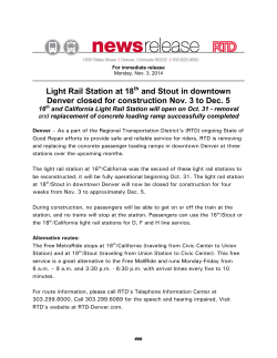
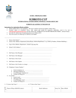
Discipline: Engineering (Track & Civil) Category: Standard Rail Profiling - Turnouts ETM-03-02 Applicability ARTC Network Wide Primary Source ARTC NSW Standard LMP 03 Document Status Version Date Reviewed Prepared by Reviewed by Endorsed Approved 1.3 14 May 15 Standards Stakeholders Manager Standards GM Technical Standards 15/05/2015 Amendment Record Version Date Reviewed Clause Description of Amendment 1.0 01 Dec 09 Implementation draft. Supersedes NSW Standard LMP 03 v1.4 1.1 18 Jun 10 Banner added regarding mandatory requirements in other documents and alternative interpretations. 1.2 08 Apr 11 14 Class A, B and C tracks changed to Heavy Haul, Interstate and Intrastate Lines 1.3 14 May 15 Various Updated title to "Rail Profiling - Turnouts" (previously "Rail Grinding Turnouts"), extended to network wide applicability (previously NSW Standard), replaced the use of the word grind with profile, deleted competencies section, other minor updates throughout. © Australian Rail Track Corporation Limited 2011 Disclaimer: This document has been prepared by ARTC for internal use and may not be relied on by any other party without ARTC’s prior written consent. Use of this document shall be subject to the terms of the relevant contract with ARTC. ARTC and its employees shall have no liability to unauthorised users of the information for any loss, damage, cost or expense incurred or arising by reason of an unauthorised user using or relying upon the information in this document, whether caused by error, negligence, omission or misrepresentation in this document. This document is uncontrolled when printed. Authorised users of this document should visit ARTC’s intranet or extranet (www.artc.com.au) to access the latest version of this document. Engineering (Track & Civil) Standard ETM-03-02 Rail Profiling - Turnouts Contents Contents 1 Purpose .................................................................................................. 4 2 Scope ...................................................................................................... 4 3 Definitions .............................................................................................. 4 4 Rail Profiles ............................................................................................ 5 4.1 Profiles and Templates........................................................................ 5 4.2 Template Fabrication .......................................................................... 5 5 Preparation for Profiling ......................................................................... 7 6 Template Application .............................................................................. 7 6.1 Placement ......................................................................................... 7 6.2 Tolerance to Template ........................................................................ 7 6.3 Allowance for Rail Rotation .................................................................. 7 6.4 Gauge Corner Relief ........................................................................... 7 6.5 Field Side Relief ................................................................................. 7 7 Minimum Metal Removal for Corrective Profiling .................................... 8 8 Minimum Metal Removal for Preventive Profiling ................................... 8 9 Surface Finish ......................................................................................... 8 9.1 Profiling Facets .................................................................................. 8 9.2 Other Surface Irregularities ................................................................. 8 10 Profiling Operation ................................................................................. 8 11 Monitoring and Control ......................................................................... 10 11.1 Inspection of Profiling ........................................................................10 11.2 Calibration ....................................................................................... 10 11.3 Monitoring ....................................................................................... 10 11.4 Records to be Kept ............................................................................10 12 Profiling Application Decisions Required ARTC ..................................... 11 12.1 The Application of Templates .............................................................. 11 12.2 Removal and Replacement of Obstructions ...........................................11 12.3 Application of the Locating Lug on Low Rail and Tangent Rail Templates ..11 12.4 Rail Rotation Under Load ...................................................................11 12.5 Gauge Corner Relief ..........................................................................11 12.6 Field Side Relief ................................................................................11 12.7 Minimum Metal Removal for Corrective Profiling....................................11 Version 1.3 Date of last revision: 14 May 15 This document is uncontrolled when printed. See ARTC Intranet for latest version. Page 2 of 14 Engineering (Track & Civil) Standard ETM-03-02 Rail Profiling - Turnouts Contents 12.8 Transitioning the Removal of Long Wavelength Corrugations ..................13 13 Profiling Strategy.................................................................................. 14 13.1 General ........................................................................................... 14 13.2 Profiling of new rail (mandatory requirements) .....................................14 13.3 Guidelines for Preventive Profiling ....................................................... 14 13.4 Guidelines for Corrective Profiling ....................................................... 14 Version 1.3 Date of last revision: 14 May 15 This document is uncontrolled when printed. See ARTC Intranet for latest version. Page 3 of 14 Engineering (Track & Civil) Standard ETM-03-02 Rail Profiling - Turnouts Purpose Mandatory requirements also exist in other documents. Where alternative interpretations occur, the Manager Standards shall be informed so the ambiguity can be removed. Pending removal of the ambiguity the interpretation with the safest outcome shall be adopted. 1 Purpose This document establishes standards for rail profiles to be used on track managed by Australian Rail Track Corporation (ARTC) and describes the methods by which the rail profiles are to be applied and the quality standards to be achieved. Alternative requirements may be applied as part of an approved regional profiling strategy. Some mandatory rail profiling frequencies are nominated and recommended frequencies are detailed in Technical maintenance Plans. 2 Scope The standard addresses only the considerations for turnout profiling where these are different to the requirements of ETM-01-02 which covers plain track profiling. Profiling standards have evolved from work undertaken by the Wheel/Rail Committee (ARTC, ARTC, StateRail, National Pacific (formerly National Rail and FreightCorp) to develop suitable, matching rail and wheel profiles. Significant additional work has been undertaken in the implementation of these profiles through profiling strategies in the Heavy Haul areas of the Hunter Valley, the North Coast and the Metropolitan Division. 3 Version 1.3 Definitions ARTC Representative A person who has formally been allocated maintenance responsibility for a particular area at Engineer level or a person who has been delegated with engineering authority with respect to Rail Condition/Profiling Management by ARTC. Running Surface: The zone on top of the rail head which makes contact with the wheel tread (refer to Figure 1). Gauge Corner: The top corner of the rail above the gauge face (refer to Figure 1). Gauge Corner Relief: Clearance between the wheel profile and the rail profile to reduce wheel rail contact in the gauge corner region (refer to Figure 1). Gauge Face: The zone of the rail head facing the inside of the track. In the tighter curves the gauge face may be worn due to contact with the wheel flange. Field Side: The side of the rail opposite the gauge face (refer to Figure 1). Field Side Relief: Clearance between the wheel profile and the rail profile to reduce wheel rail contact on the head of the rail on the far field side (refer to Figure 1). Contact Band: The contact position of the wheels on the rail as evidenced by the shiny worn surface. This generally applies to contact occurring on the running surface of the rail. Gauge Bar: A rod or bar section which sits between and normal to the rails to provide a superelevated reference for the application of the template. Rail Profiling Template: A template used to fit over the head of the rail to show the relationship of the ground rail to the defined rail profile. Checking Locations: Specific points marked on the rail where the achievement of the defined rail profile and/or metal removal is checked and monitored. “Preventive or Cyclic Profiling”: Profiling carried out to a regular schedule for the purpose of maintaining the rail profiles, preventing or inhibiting the growth of defects, and maintaining the surface condition of the rail (particularly in terms of corrugations and local vertical irregularities), with a minimum metal removal of 0.2 mm from the rail contact surface each profiling cycle. Date of last revision: 14 May 15 This document is uncontrolled when printed. See ARTC Intranet for latest version. Page 4 of 14 Engineering (Track & Civil) Standard ETM-03-02 Rail Profiling - Turnouts Rail Profiles “Corrective or Defect Profiling”: Profiling to remove specific defects in the rail. Such defects may occur over a relatively long track section (for example: rail corrugations or extensive rolling contact fatigue) or over relatively short track sections (for example: wheelburns or isolated rolling contact fatigue defects). “New Rail Profiling”: Profiling to profile of rails which have been in track for less than 10 Million Gross Tonnes (MGT). “Previously profiled Rail Profiling”: Profiling of rail to profile which has been profile ground previously but is beyond the specified cycle, noting that the actual rail profiling effort in this case will depend on the tonnage level beyond the specified cycles which the rails have experienced, i.e. more profiling effort will be required as the tonnage beyond the specified limits increases. Figure 1: Regions in 60kg/m rail 4 Rail Profiles 4.1 Profiles and Templates The profile implemented by profiling shall be the new modified tangent profile RTG2000 (also known as TGT). Details of the profile and template are contained in ETM-01-02. The profiles obtained shall be checked on both stock and closure rails, using the appropriate templates (refer to Figure 2). The rail shape is designed to suit the wheel profiles and the rolling stock using the track. As part of the design the contact band width and location position is determined. The designed rail shapes required have been converted into matching templates for use with the rail profiling operation. In certain cases, there may be a requirement to apply defect profiling, which will entail the removal of a considerable amount of metal primarily from the running surface of the rail along a certain length of track. In all of these cases, the profiling shall be completed by the implementation of the rail profile specified, which shall conform with all of the standards applied to the normal preventive profiling practice. 4.2 Template Fabrication Rail template requirements are given in ETM-01-02. Version 1.3 Date of last revision: 14 May 15 This document is uncontrolled when printed. See ARTC Intranet for latest version. Page 5 of 14 Engineering (Track & Civil) Standard ETM-03-02 Rail Profiling - Turnouts Rail Profiles Figure 2 Acceptable Profiling Finish at Switch and Stock Rails Version 1.3 Date of last revision: 14 May 15 This document is uncontrolled when printed. See ARTC Intranet for latest version. Page 6 of 14 Engineering (Track & Civil) Standard ETM-03-02 Rail Profiling - Turnouts 5 Preparation for Profiling Preparation for Profiling Turnouts must be examined prior to profiling. Profiling should only be conducted on track that has good top and line, preferably after the track has been surfaced. The inspection must identify all track obstructions that could prevent profiling within or adjacent to the turnout/(s). This includes: • high ballast • lubricators • wayside monitoring devices • guardrails, checkrails or other equipment that protrude above rail level by more than 10mm* All such equipment shall be removed prior to profiling and replaced after profiling in accordance with the requirements specified by ARTC. * the amount of protrusion allowed may vary depending on the characteristics of the profiling machine being used. This should be confirmed prior to the inspection being carried out. 6 Template Application 6.1 Placement Rail template placement requirements are given in ETM-01-02. 6.2 Tolerance to Template Rail template tolerance requirements given in ETM-01-02 are to be used for turnouts except with regard to the following: 6.3 • All flow on the gauge side of rails is to be removed. • The lug on the template does not have to fit snug against the gauge face of the rail as long as the ground rail profile is no more than 5 mm from the edge of the template. There is no requirement to reduce this distance by profiling. Allowance for Rail Rotation Rails exhibit different rotation characteristics under traffic which depend on the rail size, the traffic type, the sleeper and fastening type and the track curvature. ARTC will specify the amount of rail rotation to be allowed. The default value is zero. 6.4 Gauge Corner Relief Generally any required gauge corner relief is built into the rail template and no additional gauge corner relief is to be applied. 6.5 Field Side Relief Generally any required field side relief is built into the template. ARTC may specify additional relief requirements but only up to the tolerances specified. (See 6.2). Version 1.3 Date of last revision: 14 May 15 This document is uncontrolled when printed. See ARTC Intranet for latest version. Page 7 of 14 Engineering (Track & Civil) Standard ETM-03-02 Rail Profiling - Turnouts 7 Minimum Metal Removal for Corrective Profiling Minimum Metal Removal for Corrective Profiling The ARTC representative will specify the metal removal requirements for corrective profiling of transverse profile. This may allow some gauge corner cracking/ checking to remain in track after profiling. 8 Minimum Metal Removal for Preventive Profiling Metal removal requirements are as specified in ETM-01-02 excepting where ARTC makes allowance for lesser metal removal. (see Section 6.2). 9 Surface Finish 9.1 Profiling Facets Maximum facet width and other requirements are given in ETM-01-02. 9.2 Other Surface Irregularities The requirements for identification and removal of other surface irregularities and for the rail surface finish are given in ETM-01-02. 10 Profiling Operation The initial profiling of turnouts shall be conducted on the through road and continued beyond the points and crossing for a distance of 15-20 m or as required to overlap with the Main Line profiling. The subsequent profiling of the turnout road shall finish at the end of the switch, to avoid additional profiling of the rails on the through road. Profiling of the turnout road should continue beyond the crossing for 15 to 20m or as required to complete a full crossover. When profiling is conducted on a turnout and/or crossing all possible parts of that turnout and/or crossing shall be ground (including switches, closure and stock rails). This will require the resetting of switches during the profiling operation. (Signalling and other support requirements for this must be in place for restoration of the work). Generally, standard profiling passes can be applied up to 0.5 m from the nose of the crossings and up to 1 m from the tip of the switches. Special care must be taken with the profiling applied within these distances to ensure that excessive metal is not removed. For those parts that can still be ground, this will usually entail the application of only a limited number of profiling passes (2-3) to clean up the gauge corner region and reduce the plastic flow lipping (refer to Figures 2 and 3). Some areas of the turnout may not be able to be ground by current on-track profiling machines (normally towards the tip of the switches and the crossing nose). In these cases, suitable hand held profiling devices should be used to cover the missed areas. In addition they may also be used to profile any anomalies on the gauge face of the rail (such as rail flow), which similarly have been missed by the on-track profiling machines. See figure 3 showing profiling in the vicinity of crossings. Version 1.3 Date of last revision: 14 May 15 This document is uncontrolled when printed. See ARTC Intranet for latest version. Page 8 of 14 Engineering (Track & Civil) Standard ETM-03-02 Rail Profiling - Turnouts Profiling Operation Figure 3 Acceptable Profiling Near the Nose of V Crossings At the completion of profiling the chair plates must be washed using pressurised water to remove most of the profiling particles/dust. All work must be carried out in accordance with relevant OH&S requirements, ARTC Standards and Environmental Licenses, relevant legislation and relevant Safeworking requirements (including for work affecting interlocked points). Version 1.3 Date of last revision: 14 May 15 This document is uncontrolled when printed. See ARTC Intranet for latest version. Page 9 of 14 Engineering (Track & Civil) Standard ETM-03-02 Rail Profiling - Turnouts 11 Monitoring and Control 11.1 Inspection of Profiling Monitoring and Control The achievement of profiling tolerances and metal removal must be checked on completion of the profiling work and prior to the running of trains. Checking locations must be examined for profile and metal removal and the remainder of the turnout checked visually to ensure that the specified defect removal requirements and surface condition have been achieved. Close visual examination is to be carried out at crossings and switches and stockrails. Profiles are to be checked at all turnouts at the following locations - switches, stockrails, crossings and in the approximate middle of the turnout. No paint-marking of checking locations is required. The required contact band width on the running surface shall be checked by painting the running surface of the rails at the checking locations following profiling, and inspection after at least 3 or 4 trains. Any abnormal observations (i.e. when the actual contact band is outside the recommended limits) are to be noted and reported to ARTC for monitoring for possible future action. 11.2 Calibration Template calibration requirements are as specified in ETM-01-02. 11.3 Monitoring Monitoring requirements are as specified in ETM-01-02. 11.4 Records to be Kept The technical details for either preventive or corrective rail profiling, need to be recorded in an electronic database. These are specified below. They are similar to the requirements in ETM-0102. • Profiling machine. • Date of profiling and inspection. • Location of turnout on which profiling was carried out specifying from and to km, description of the turnout (eg xover, diamond, catchpoints) and the points number(s). • Nature of the profiling strategy adopted (eg preventive/corrective/defect). • Rail type. • Effective track kilometres ground (work completed satisfactorily) counting both the mainline and turnout road. • Location of any section within a track segment that has not been ground, and the reason for not profiling (for example: high ballast, crossing, etc). • Rail height before and after profiling (or minimum metal removal), to closest 0.05mm. • Number of profiling passes applied to each rail. • Profiling efficiency of machine, ie number of profiling motors working. • Details of any condition from pre-profiling inspection or any other specific inspections of rail condition. • Details of the rail contact band assessments carried out. • Details of any non-conformances in the profiling process or standard of completion. The above information shall be available in daily form within 24 hours of the end of each shift, and in weekly form within 48 hours of the completion of each week’s work. Version 1.3 Date of last revision: 14 May 15 This document is uncontrolled when printed. See ARTC Intranet for latest version. Page 10 of 14 Engineering (Track & Civil) Standard ETM-03-02 Rail Profiling - Turnouts Profiling Application Decisions Required ARTC 12 Profiling Application Decisions Required ARTC 12.1 The Application of Templates Refer to ETN-01-02. 12.2 Removal and Replacement of Obstructions The ARTC representative must specify removal and replacement requirements for trackside equipment such as rail lubricators and trackside warning devices, railed checkrails and guardrails and for adjustments required at switches including signalling. The period such devices are absent may have an impact on infrastructure and operations. 12.3 Application of the Locating Lug on Low Rail and Tangent Rail Templates Refer to section 6.2. 12.4 Rail Rotation Under Load Rail rotation under load will affect how the wheel interfaces with the rail. Consequently, such rail rotation should be accounted for when applying a template during rail profiling. The ARTC representative may determine the rotation required (normally to the nearest degree). The rotation under load can be determined by measurement or assessment for each section of track. Alternatively default values are given in Section 6.3. 12.5 Gauge Corner Relief Gauge corner relief is not applicable in turnouts. 12.6 Field Side Relief The ARTC representative should specify additional field side relief when, after the application of the normal templates, there is still evidence of excessive tread hollowing on wheels (this is normally observed as a well developed contact band extending beyond the contact bands and towards the field side of the rail head). Under the above circumstances, additional field side relief needs to be applied to ensure that minimum wheel contact occurs in the field side region, i.e. within approximately 15 mm from the field side rail face. In such cases, the ARTC representative may nominate additional field side relief. However, in introducing such relief, the required tolerancing shall be applied with reference to the template; namely: up to 0.3-0.5 mm at an angle (to the horizontal) of -1° (measured anti-clockwise) and up to 0.5-0.7 mm at an angle of -2°. The nominated measurements can be checked with suitable feeler gauges. The additional field side relief should not extend into the contact zone. There is no requirement to address the problems relating to passenger lines subject to occasional contact from locomotives with tread hollowed wheels (referenced in ETM-01-02). This problem does not occur in turnouts. 12.7 Minimum Metal Removal for Corrective Profiling When profiling relatively new turnouts for the first time, in order to reduce the metal removal requirements, the specified minimum depth of metal removal on the contact surface (0.2 mm) can be reduced to 0.0 mm near the field side edge of the contact surface (refer to Figure 2). The ARTC representative must specify the metal removal requirements for corrective profiling. These arise primarily because of rolling contact fatigue defects present in rails that have not Version 1.3 Date of last revision: 14 May 15 This document is uncontrolled when printed. See ARTC Intranet for latest version. Page 11 of 14 Engineering (Track & Civil) Standard ETM-03-02 Rail Profiling - Turnouts Profiling Application Decisions Required ARTC been cyclic ground. Such damage may inhibit the routine ultrasonic inspection of the rails, particularly if located in the gauge corner region (gauge corner checking). Complete removal of the severe gauge corner checking defects is not recommended as it requires considerable metal removal and hence rail profiling effort and it removes protective work hardened material from the surface (see figure 3). The recommended procedure to be implemented in these cases is as follows: • Remove a minimum of 0.2 mm (and usually more than 0.4-0.5mm but generally no more than 0.8mm subject to approval from the ARTC representative) of metal from all contact surfaces including the gauge region, as specified in Section 8. • Ensure that all checking cracks have been removed from the running surface above the rail web, and preferably from a distance of 20-25 mm from the gauge corner (exclusive) towards the field side. As illustrated in Figures 3 and 4, some gauge corner checking may be left on the rails. • Establish the recommended profiles, and where the gauge corner is affected allow a gauge corner relief of 0.3-0.6 mm in the high rails, to reduce the gauge corner contact for a limited time. It should be emphasised that the profiling facet limits as specified in Section 9.1 must also still be observed within the gauge corner relieved zone. • Note the track sections in which the above procedure has been implemented, so that (depending on the degree of damage) in following profiling cycles the additional gauge corner relief may be able to be reduced to within the normal limits specified in Section 6.2. It is emphasised however that the above procedure should not be required when the rails have been subjected to a number of preventive profiling cycles. Version 1.3 Date of last revision: 14 May 15 This document is uncontrolled when printed. See ARTC Intranet for latest version. Page 12 of 14 Engineering (Track & Civil) Standard ETM-03-02 Rail Profiling - Turnouts Profiling Application Decisions Required ARTC Figure 4 Initial and acceptable residual gauge corner defects before and after profiling 12.8 Transitioning the Removal of Long Wavelength Corrugations Transition arrangements are not applicable in turnouts. Version 1.3 Date of last revision: 14 May 15 This document is uncontrolled when printed. See ARTC Intranet for latest version. Page 13 of 14 Engineering (Track & Civil) Standard ETM-03-02 Rail Profiling - Turnouts Profiling Strategy 13 Profiling Strategy 13.1 General This profiling strategy contains: mandatory requirements for profiling new turnouts (or new turnout steelwork where existing bearers are kept); guidelines for preventive profiling; and guidelines for corrective profiling. The requirements are applicable to Heavy Haul and Interstate Lines and heavily utilised Intrastate Lines. Where targeted profiling strategies have been developed for specific lines or regions then these will take precedence. Such alternative strategies must be approved by ARTC. The guidelines are provided for the preventive profiling strategy and as such will provide an indication of the minimum rail profiling requirements. In the initial stages additional profiling may be necessary to rectify defective track sections. The standard does not cover manual profiling for minor maintenance associated with crossings and switches. 13.2 Profiling of new rail (mandatory requirements) Any new turnouts are to be profile ground within 8 MGT for Standard Carbon rails and 10 MGT for Head Hardened rails (or 20% of the profiling cycle for preventive profiling detailed in Technical Maintenance Plans, whichever is the larger) following installation. 13.3 Guidelines for Preventive Profiling The recommended guidelines for preventive rail profiling are to be the more stringent of the requirements for the main line as given in ETM-01-02 Rail Profiling Standard for Plain Track and for the turnout road as given in Table 1 below. Note that tonnages on the turnout road are to be used in Table 1. Table 1: Guidelines for Preventive Profiling Turnout Road Turnout Type Rail Type 1:8.25 1:10.5 1:15 or higher Head Hardened 13 MGT 18 MGT 25 MGT Standard Carbon 8 MGT 13 MGT 18 MGT To allow for track possession and profiling irregularities a tolerance of up to 20% of the recommended cycle tonnages given in Table 1 is applicable. The nominal profiling period however will generally be maintained. Because of adverse wheel/rail contact conditions, the adequate for some track sections. Such sections should be adjusted to a different cycle category. An example could efforts which may exhibit higher deterioration rates and profiling. profiling determined might not be reported, monitored and if necessary be rails subjected to higher tractive hence would require more frequent The nominal profiling period between profiles should be achieved at least on average. If necessary individual cycles may be adjusted to suit particular circumstances but generally within the maximum allowable periods. 13.4 Guidelines for Corrective Profiling Special profiling requirements are given in ETM-01-02. Version 1.3 Date of last revision: 14 May 15 This document is uncontrolled when printed. See ARTC Intranet for latest version. Page 14 of 14


© Copyright 2026