
EZ DROP THROUGH ANCHOR With Swivel Ring 5,000
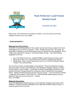
EZ DROP THROUGH ANCHOR With Swivel Ring 5,000-lbf / 22kN Model: EZA6200 Assembled in the USA IMPORTANT!!! ALL PERSONS USING THIS EQUIPMENT MUST READ AND UNDERSTAND ALL INSTRUCTIONS. FAILURE TO DO SO MAY RESULT IN SERIOUS INJURY OR DEATH. USERS SHOULD BE FAMILIAR WITH PERTINENT REGULATIONS GOVERNING THIS EQUIPMENT. ALL INDIVIDUALS WHO USE THIS PRODUCT MUST BE PROPERLY INSTRUCTED ON HOW TO USE THIS DEVICE. V1.7 Read This Instruction Manual Carefully Before Using This Equipment. User Instructions must always be available to the user and are not to be removed except by the user of this equipment. For proper use, see supervisor, User Instructions, or contact the manufacturer. Compliant fall protection and emergency rescue systems help prevent serious injury during fall arrest. Users and purchasers of this equipment must read and understand the User Instructions provided for correct use and care of this product. All users of this equipment must understand the instructions, operation, limitations and consequences of improper use of this equipment and be properly trained prior to use per OSHA 29 CFR 1910.66 and 1926.503 or applicable local standards. Misuse or failure to follow warnings and instructions may result in serious personal injury or death. PURPOSE The EZA6200 is an anchorage connector designed to function as an interface between the anchorage and a fall protection, work positioning, rope access, or rescue system for the purpose of coupling the system to the anchorage. Any references to “anchorage connector” in this manual include, and apply to, the EZA6200. USE INSTRUCTIONS 1. A user must be of sound mind and body to properly and safely use this equipment in normal and emergency situations. Users must have a physician ensure they are clear of any medical conditions that may affect the proper and safe use of this equipment in normal and emergency situations. 2. Before using a personal fall arrest system, user must be trained in accordance with the requirements of OSHA 29 CFR 1910.66 in the safe use of the system and its components. 3. Use only with ANSI/OSHA compliant personal fall arrest or restraint systems. The anchorage must have the strength capable of supporting a static load, applied in the directions permitted by the system, of at least 5,000-lbf (22kN) in the absence of certification. 4. The user shall be equipped with a means of limiting the maximum dynamic forces exerted on the user during the arrest of a fall to a maximum of 6 kN (1350-lbf ) 5. Use of this product must be approved by an Engineer or other qualified person to be compatible with any and all structural & operational characteristics of the selected installation location and system to be connected to this anchorage connector. 6. The anchorage connector must be inspected prior to each use for wear, damage, and other deterioration. If defective components are found the anchorage connector must be immediately removed from service in accordance with the requirements of OSHA 29 CFR 1910.66 and 1926.502. 7. The anchorage connector should be positioned in such a way that minimizes the potential for falls and the potential fall distance during use. The complete fall protection system must be planned (including all components, calculating fall clearance, and swing fall) before using. 8. A rescue plan, and the means at hand to implement it, must be in place that provides the prompt rescue of users in the event of a fall, or assures that users are able to rescue themselves. 9. After a fall occurs the anchorage connector must be removed from service and destroyed immediately. USE LIMITATIONS: The anchorage connector shall not be used outside its limitations, or for any purpose other than that for which it is intended. 1. The anchorage connector is designed for single user, with a capacity up to 310 lbs (140 kg) including clothing, tools, etc. 2. The anchorage connector may be pulled in any direction shown in the LOADING CONDITIONS DIAGRAM. 3. The anchorage connector is designed to be used in temperatures ranging from -40ºF to +130ºF (-40°C to +54°C). 4. Do not expose the anchorage connector to chemicals or harsh solutions which may have a harmful effect. 5. Do not alter or modify this product in anyway. 6. Caution must be taken when using any component of a fall protection, work positioning, rope access, or rescue system near moving machinery, electrical hazards, sharp edges, or abrasive surfaces, as contact may cause equipment failure, personal injury, or death. 7. Do not use/install equipment without proper training by a “competent person” as defined by OSHA 29 CFR 1926.32(f ). 8. Do not remove the labeling from this product. 9. Additional requirements and limitations may apply depending on anchorage type and fastening option utilized for installation. All placements must be approved by an engineer or other qualified person. 10. This anchorage connector should not be used as part of a horizontal lifeline system that has not been designed and or approved to be used with 5,000-lbf anchorage connectors. 11. The anchorage connector should only be used for personal fall protection and not for lifting equipment. COMPATIBILITY LIMITATIONS All anchorage connector must only be coupled to compatible connectors. OSHA 29 CFR 1926.502 prohibits snaphooks from being engaged to certain objects unless two requirements are met: it must be a locking type snaphook, and it must be “designed for” making such a connection. “Designed for” means that the manufacturer of the snaphook specifically designed the snaphook to be used to connect to the equipment listed. The following connections must be avoided, because they can result in rollout* when a nonlocking snaphook is used: • Direct connection of a snaphook to horizontal lifeline. • Two (or more) snaphooks connected to one D-ring. • Two snaphooks connected to each other. • A snaphook connected back on its integral lanyard. • A snaphook connected to a webbing loop or webbing lanyard. • Improper dimensions of the D-ring, rebar, or other connection point in relation to the snaphook dimensions that would allow the snaphook keeper to be depressed by a turning motion of the snaphook. *Rollout: A process by which a snaphook or carabiner unintentionally disengages from another connector or object to which it is coupled. (ANSI Z359.1-2007) PERFORMANCE: Static Tensile Strength: 5000-lbf (22kN) Maximum Capacity: one worker with max weight of 310-lbs when used as a single point anchorage connector for personal fall arrest or restraint system. DIMENSIONS: Weight: Verys by cable length Length: Custom cable lenght Diameter: 4”Ø x 3/16” REGULATORY COMPLIANCE: ANSI Z359.1-2007, ANSI Z359.7-2011, OSHA 1926.502, OSHA 1910.66, COMPONENT MATERIALS: Aircraft Cable: Cable Coated Steel: Plate Polyurethane: Tubing Zinc Plated Steel: Swivel Ring Aircraft Cable WARNING LABEL LOCATIONS (length specified by customer) Polyurethane Sleeve EZA6200 4”Ø 3/16” Plate Swivel Ring Installation: 1. The DTA-5k drop through anchor can only be used on a horizontal surface that is above the users location. 2. Locate or create a through hole in concrete, steel or metal grating capable of withstanding a 5,000-lbf. Static load or meeting OSHA 1926.502 requirements for a safety factor of two. (Refrence figure 1-A below for dimentional requirements.) 3. Place cable through the hole from top side. The label on plate should be facing up. Plate must rest flat and flush on the mounting surface. 1-3/4” to 2”Ø Hole size (A) y edge min from an (4.1cm to 4.4cm) (B) min HOLE REQUIRMENT CHART Material: (A)” Minimum distance from edge/corner (B)” thickness Concrete Steel 12” in. (30.5 cm) 4” in. (10 cm) 4” in. (10 cm) 1/4” in. (.635 cm) MAINTENANCE, CLEANING AND STORAGE Cleaning periodically will prolong the life and proper functioning of the product. The frequency of cleaning should be determined by inspection and by severity of the environment. Clean with compressed air and/or a stiff brush using plain water or a mild soap and water solution. Do not use any corrosive chemicals that could damage the product. Wipe all surfaces with a clean dry cloth and hang to dry, or use compressed air. When not in use, store anchorage connectors in a cool, dry, clean environment, out of direct sunlight and free of corrosive or other degrading elements. INSPECTION AND MAINTENANCE LOG MODEL NUMBER: DATE OF MANUFACTURE: Date Part Number Comments Inspector Name Inspection: Official periodic inspection must be made at least annually. The inspection must be performed by a qualified person other than the intended user. If severe weather or conditions exist then inspections must be carried out more frequently. All inspection results must be logged in the space provided above. (It is recommended that the anchor device is marked with the date of the next or last inspection.) *If any damage that could affect the strength or operation of the device, or unsafe conditions are found, proper disposal is required. The anchorage connector must be rendered unusable and then properly discarded. Product Warranty, Limited Remedy and Limitation of Liability WARRANTY: THE FOLLOWING IS MADE IN LIEU OF ALL WARRANTIES OR CONDITIONS, EXPRESS OR IMPLIED, INCLUDING THE IMPLIED WARRANTIES OR CONDITIONS OF MERCHANTABILITY OR FITNESS FOR A PARTICULAR PURPOSE. Equipment offered by EZ Lifline is warranted against factory defects in workmanship and materials for a period of one year from date of purchase or first use by the original owner. LIMITED REMEDY: Upon notice in writing, EZ Lifline will repair or replace all defective items at EZ Lifline’s sole discretion. EZ Lifline reserves the right to require that the defective item be returned to its plant for inspection before determining the appropriate course action. Warranty does not cover equipment damage resulting from wear, abuse, damage in transit, failure to maintain the product or other damage beyond the control of EZ Lifline. EZ Lifline shall be the sole judge of product condition and warranty options. This warranty applies only to original purchaser and is the only warranty applicable to this product. Please contact EZ Lifline technical service department for assistance. LIMITATION OF LIABILITY: IN NO EVENT WILL EZ LIFLINE BE LIABLE FOR ANY INDIRECT, INCIDENTAL, SPECIAL OR CONSEQUENTIAL DAMAGES INCLUDING, BUT NOT LIMITED TO LOSS OF PROFITS, IN ANY WAY RELATED TO THE PRODUCTS REGARDLESS OF THE LEGAL THEORY ASSERTED. EZ LifLine, LLC. 405 Watertown Road Waterford, OH 45786 1(800) 417-9272 / www.ezlifline.com


© Copyright 2026