
Modeling and Control of Motion Axes in a Pen Plotter
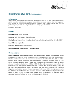
Modeling and Control of Motion Axes in a Pen Plotter Proposal for Final Project ECE456 Fall 2011 Names Deleted The proposed project is a two axis pen plotter incorporating feedback control on both motion axes. Proposed System: The proposed plotter will be constructed as a rotating drum with a single transverse motion axis. The paper will be fixed to the drum which is driven via a PMDC motor with a small PMDC motor used as a tachometer for feedback. The transverse axis will carry a fixed pen and will be controlled by a DC servomotor. The servomotor on hand for this axis incorporates an optointerrupter output and is fitted for a synchronous belt which can be used to move the pen carriage. The motors for both axes will be driven by a L298N bridge driver, and the velocity feedback from the drum generator will be conditioned with a simple op-amp circuit. These drives will be controlled by the supplied Arduino. Figure 1: The Mechanical System In Final Assembly Block Diagram of Two Axis Pen Plotter ½ PWM Motor Driver Drum DC Motor Gear Train Tacho generator ½ PWM Motor Driver DC Motor Transverse Direct Connection Encoder Arduino DATA ACQUISITION / PC Figure 2: The Basic System Block Diagram Figure 3: Tentative Electrical Hardware Interface Level Shifter Development and Demonstration Methodology: Utilizing Simulink/Simscape tools, models for each axis will be developed independently. Similar to the servomotor lab procedure, these subsystems will be analyzed for fitting parameters which are otherwise difficult to measure. A PID or appropriate controller will be tuned for a reasonable performance on each axis and then each axis will be tested independently. The system as described should be able to plot a continuous line image within the area of a page limited by the drum height and circumference. By driving an axis at a constant velocity and applying a position step to the remaining axis, the step response of an axis can be physically plotted to illustrate the effect of controller tuning. Once ancillary code or simulink models are developed such that both axes can operate in tandem, other output patterns can also be used as are seen fit for demonstration. Expected Results: The individual axes should be reasonably simple to bring to a working state. Achieving fast rise time with quick settling and minimal skipping may be difficult since the mechanical system will contribute some discontinuous behaviors due to the haste of assembly and the fact that this course isn’t a mechanical design focus: Axial drum play being aggravated by helical drive gearing Drum runout Pen wobble/chatter due to poor shafting fitup That said, the transverse axis will probably be able to meet much better slewing demands than the drum axis. The drum axis has a much larger inertia and is torque limited by a slip clutch in the motor bushing. Since the plotter is being developed without a strict definition of how it should be able to perform (if this were to have relatively symmetrical axis slewing or not), this is not necessarily a problem. Similarly, pen skipping at high slew rates will likely be an issue because we will not be using technical or plotter pens. So long as the modeling and control objectives of this project are met, this is an acceptable shortcoming of the mechanical system alone. Required Items: On hand are the following: 1x L298N bridge driver with diodes 1x PMDC motor (for generator) 1x PMDC motor and pictured gear train 1x DC servomotor Various linear shafting and bushings Synchronous belts and sheaves Arduino and other misc electrical components


© Copyright 2026