
Window Treatment Horizontal Blinds Bali Classics Mini Blinds PART 1—GENERAL
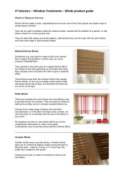
Springs Window Fashions LP
Window Treatment Horizontal Blinds
Bali Classics™ Mini Blinds
PART 1—GENERAL
1.01 DESCRIPTION
A. Related Requirements
1. The Conditions of the Contract (General and Supplementary, and other
Conditions), and Division 1 General Requirements (if any) are part of this
section. (Delete or retain as appropriate.)
CON T R AC T
LADDER DRUM
TILT ROD
SUPPORT TILT ROD
MOUNTING
ADJUSTMENT
TABS
END SUPPORT
BRACKET
CORD LOCK
CLUTCH
TILTER
LIFT CORD
EXTENSION
BRACKETS
1.02 QUALITY ASSURANCE
A. Job Mock-Up: (Describe)
1.03 SUBMITTALS
A. Manufacturer's Product Data: Submit manufacturer's descriptive product
data and installation instructions for each type of blind specified.
B. Shop Drawings: Submit shop drawings indicating the following:
1. Field-measured dimensions of openings scheduled to receive blinds.
2. Illustrations of special accessory components not included in
manufacturer's product data.
3. Details of head and sill conditions, corner conditions, and conditions
between adjacent blind units.
C. Color Sample: Submit two 6-inch (0.15m) samples of material indicating full
color range and color variation.
D. Product Sample: Submit one 16-inch wide by 24-inch long fully functional
sample blind.
E. Maintenance Material (Extra Stock): (Describe)
OPTIONAL
RING PULL
LADDER RETAINER
WAND
BRAIDED LADDER
BOTTOMRAIL END CAP
BOTTOMRAIL
END CAP HOLD-DOWN PIN
UNIVERSAL
HOLD-DOWN BRACKET
(SILL/JAMB APPLICATION)
PART 2—PRODUCTS
2.01 HORIZONTAL BLINDS
A. Manufacturer and Product:
1. Manufacturer: Springs Window Fashions LP
a. Product: Bali Classics Custom Mini Blind
b. Options: (Describe)
c. Color(s): Selected from Bali color standards.
B. Product Description:
1. Steel Channel Headrail: "U"-shaped 1-inch high by 1 1/2-inch deep
channel shall measure 0.025" thick, and be fabricated from phosphate
treated steel with rolled edges at top and with prime coat of vinyl primer
and finished coat of polyester baked enamel to match bottomrail and end
support brackets and to coordinate with slats. Headrail shall be rollformed.
2. Head Channel Hardware: Hardware shall be acetal low friction thermoplastic and guide lift cords and ladders in the head channel preventing
wear and discoloration. Operating hardware shall be mechanically locked
into head channel, by means of snap-in fittings with no mechanical cleats
visible from underside of headrail.
3. Enclosed Metal Bottomrail: Completely enclosed tubular shape,
phosphate treated steel with prime coat of vinyl primer and finished coat of
polyester baked enamel matching headrail and coordinating with slat color.
Bottomrail shall be roll-formed with locking groove to receive dust cover.
Thermoplastic protective caps in bottom of rail shall be used to secure ladder ends and assure window sill protection. Hold-down bracket pins shall
be available. Bottomrail shall measure 0.025" thick.
4. Slats: Slats shall be aluminum alloyed for maximum strength, flexibility and
resistance to corrosion. Slats shall be nominally 1-inch wide, actual 0.991inch (plus .004-inch or minus .000-inch). Standard thickness is 0.006",
optional 0.008" is available. Slats shall have a pre-coating treatment to
bond the polyester baked enamel finish coat that features our Advanced
Finishing Technology (AFT) which provides a smoother, harder, less
porous surface that provides anti-static performance to help repel dust and
anti-microbial qualities to help resist fungal and bacterial growth.
CORD
TASSELS
SPRING
CLIP
5.
6.
7.
8.
ALUMINUM SLAT
BUMPER
Classics™ Mini Blind
Slat thickness and ladder support distances shall be such that there is no
visible sag.
a. Perforated Slat Option: Available in 6 colors with a 6% openness factor. Slats are available in White Satin, Alabaster, Brushed Aluminum,
Smokey Gray, Char Brown, and Black Satin. AFT finish is not available
on perforated slats.
Tilt Rod Support: Tilt rod support shall be acetal low friction thermoplastic and shall support tilt rod. It shall provide a smooth bearing and center
the ladder drum over ladder hole. Incorporated with tilt rod support shall
be a grommet guide to guide lift cord and braided ladder through bottom
of headrail. Acetal grommet shall have beveled edges to prevent cord and
braided ladder wear and discoloration.
Ladder Drum: Shall be injection molded thermoplastic with smooth hole
edges to position ladder. Ladders will be securely attached by means of a
snap down top, eliminating the need for braided ladder clips.
Cord Lock: Cord lock shall be of a snap-in design and incorporate a
stainless steel wear guard over which cords pass and a floating shafttype
locking pin. Locking pin shall be free of abrasive teeth and offer minimum
wear to cord. Cord lock shall incorporate a "crash-proof" safety feature
that shall lock blind automatically upon release of cord. End of lift cords
shall be treated with plastic tassels.
a. Cord Guide: Cord guide shall be nickel plated steel and will guide and
center lift cords into cord lock opening.
b. Ring Pull: When supplied with a standard nominal 4" cord length, a
single ring will be attached to 2 and 4 cord blinds. Non-standard
lengths of 8" or greater will have a joiner ball located nominally 4" from
the headrail and will have two separate cords coming down from the
joiner ball, each with a separate ring, to the specified non-standard
length.
c. Top-Locking Cord Lock: An optional top-locking cord lock shall be
available which provides for locking the blind in the fully raised position
only with no intermediate locking positions other than fully lowered. The
crash-proof feature is not available with a top-locking cord lock.
Shaft Type Tilter: The tilter shall be of a worm and gear arrangement in a
totally enclosed gear case (housing). The worm (tilter shaft) shall be of clear
polycarbonate, the gear of nylon and the gear housing of acetal thermoplastic. The tilter shall be designed for smooth low friction operation and
shall incorporate a clutch mechanism to eliminate damage due to over tilting. Tilter shall be a snap-in component allowing for field removal if
required.
Window Treatment Horizontal Blinds
Bali Classics™ Mini Blinds
9.
10.
11.
12.
13.
14.
a. Tilt Wand: The tilt wand shall be a clear polycarbonate hollow rod, with
a hexagonal shape measuring approximately 1/4-inch across the
points, providing a positive, comfortable grip. The wand shall hang vertically by its own weight and should be of sufficient length for easy
access and operation. Wand shall be attached to the tilter shaft by means of
a spring clip and shall be easilly detached and reattached in the field.
b. Tilt Ring: An optional tilt ring shall be attached to the tilter shaft in lieu of a
wand via the tilter shaft link with field provision of a pole-hook for operation.
c. Tilt Limiter: An optional single-range tilt limiter shall allow a select range of
slat tilting operation including a fixed angle if so specified.
Cord Type Tilter: The tilter shall be a direct drive system. The direct drive
system will utilize a hex tilt rod ladder drum in place of the shaft type tilter with tilt
cords attached to the ladder drum by means of braided ladder clips. The tilt
cords shall be equipped with plastic tassels. The tilter shall be designed for
smooth operation and shall hold the slats at any angle.
Hexagonal Tilt Rod: Tilt rod shall be electro-zinc coated solid steel. Tilt rod
shall be hexagonal in cross-section measuring 1/4-inch at its widest points. Tilt
rod shall limit torsional deflection to 6 degrees in a 30-inch test length with a
torque application of one-foot pound.
Braided Ladders (Slat Supports): Bali Classics shall have braided ladder
which will assure proper control with adequate overlap of slats in the closed
position. Distance between end ladder and end of slats will not exceed 61⁄2
inches; distance between braided ladders shall not exceed 24 inches.
a. Braided Ladder Material: Material shall be 100% high tenacity polyester
yarn. Vertical component shall be not less than 0.045-inch diameter nor
greater than 0.066-inch diameter, and shall provide maximum strength and
flexibility with minimum stretch. Horizontal component, or rungs, shall be not
less than two threads and shall be approximately 31.0mm long. Ladders
shall be of sufficient length for bottom of blind to hang with a tolerance of
plus one-half/minus zero inches of the specified length. Standard ladder will
provide 21.5mm of distance between the slats. Optional 20mm and 22.5mm
spacing is available. Ladders shall be dyed to Bali color standard.
Lift Cords: Lift cords shall be braided with polyester jacket and center core or
an approved equal construction. Size of cord shall be 1.4mm. Cords shall be
detachable, if required, and shall be of sufficient length to properly control the
raising or lowering of the blind. Lift cords shall be equipped with plastic tassels,
or optional ring pull with a 4-inch cord. Cord ends shall be securely anchored to
the bottomrail and it shall be possible to detach and attach cords. Cording
arrangements shall comply with assembly standards set for the size and weight
of the blind. Cords shall be dyed to Bali color standard.
Cord Lock and Tilter Operation Locations:
a. Bali Classics shall be made with the following cord lock and tilter location
options when viewed from within the room:
1) Tilter at left, cord lock at right (standard).
2) Cord lock at left, tilter at right (reverse).
3) Tilter and cord lock at left (both left).
4) Tilter and cord lock at right (both right).
b. On blinds less than 13 7/8-inches wide, only options 1 and 2 above apply.
End Support Brackets: Standard hinged cover end support brackets of
phosphate treated steel with prime coat of vinyl primer and finished coat of
polyester baked enamel in color to match headrail. Brackets shall be marked left
and right to facilitate installation and shall have 1 1/4-inch extra wide top to
accommodate power screwdriver. Brackets shall facilitate easy removal of head
channel. Each bracket shall be installed with a minimum of two installation
screws. Optional headrail reveal brackets for recessed pocket installation shall be
electroplated. Optional turn clip pivot brackets shall be provided for mounting
headrail of blind within extruded aluminum blind pockets.
15. Intermediate Support Brackets: Brackets shall be furnished for blinds over 48
inches wide. Maximum spacing for intermediate support brackets shall be 48
inches.
16. Extension Brackets: Optional extension brackets are available.
17. Hold-Down Brackets: Optional universal hold-down brackets for sill or jamb
installations are available.
18. End Stiffeners:
a. To add rigidity to the headrail, electroplated steel end stiffeners shall be
inserted at each end of the headrail.
b. To eliminate lateral movement and to center the blind in the window, each
end stiffener shall have a lateral adjustment tab.
19. Accent Channels: Optional side channels and bottom channels are available in
any solid slat color, except Aluminum Texture and Brushed Aluminum.
20. General: The blind shall be free of sharp edges, burrs or other defects which
might be harmful. When other materials result in improved specifications, they
may be adopted.
21. Size Limitations:
a. Standard widths: 12-143 3/4-inches (single blind on one headrail).
Blinds up to 192 inches are available as two blinds on one headrail.
Narrow blinds between 5 1/2-inches and 11 7/8-inches available with
engineering approval and normal limitations on performance and control locations. Inquire for details.
b. Maximum drop: For blinds 12-35" wide, the standard drop is 126". For
blinds wider then 35", the standard drop is 150". Longer drops up to
240" available with engineering approval and normal performance limitations. Inquire for details.
22. Color: Color of headrail, bottomrail, ladder, cord and plastic accessories shall
coordinate with slats.
2.02 FABRICATION
A. Prior to fabrication, verify actual opening dimensions by on-site measurement.
Calculate blind dimensions to fit within specified tolerances.
B. Fabricate blinds to fill openings from head to sill and jamb to jamb. Locate blind
divisions at mullions.
C. Fabricate blinds to fill all exterior window openings except at doors, door sidelights
and transoms unless noted.
PART 3—EXECUTION
3.01 INSPECTION: Verify that the work area in which the blinds will be installed is free of
conditions that interfere with blind installations and operations. Begin blind installation
only when unsatisfactory conditions have been corrected.
3.02 INSTALLATION
A. Install blinds in accordance with manufacturer's procedures except as otherwise
specified herein.
B. Install intermediate support brackets and extension brackets as needed to prevent
deflection in headrail.
C. Install blinds with adequate clearance to permit smooth operation of blinds and any
sash operators.
D. Set tilt and lift controls. Demonstrate blinds to be in smooth, uniform working order.
3.03 CLEANING
A. Clean soiled blind surfaces with a mild soap solution. Do not use steam, hot water,
bleach or any abrasive or solvent-based cleaners. Do not wash metallic colors.
B. To ensure proper drying, provide adequate ventilation for blinds, remove bottomrail
plastic end caps, and tip headrail and bottomrail to drain water.
3.04 HORIZONTAL MINI BLIND SCHEDULE:
Provide blinds at the following locations: (listing of blind locations, different options,
types, accessories and colors).
Springs Window Fashions LP P.O. Box 500, Montgomery, PA 17752
Part No. 21-5198-01 (Rev. 5/03)


© Copyright 2026