
Window Treatment Vertical Blinds Graber G71 Super-Vue Headrail PART 1—GENERAL
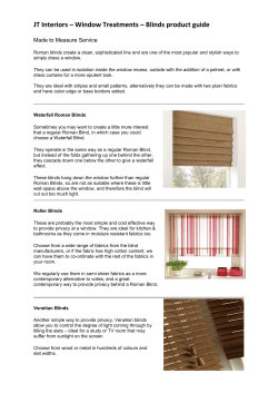
Springs Window Fashions LP
Window Treatment Vertical Blinds
Graber G71 Super-Vue® Headrail
PART 1—GENERAL
1.01 DESCRIPTION
A. Related Requirements
1. The Conditions of the Contract (General and Supplementary, and
other Conditions), and Division 1 General Requirements (if any) are
part of this section. (Delete or retain as appropriate.)
WALL BRACKET
ALUMINUM HEADRAIL
MOUNTING
CLIP
TRAVERSE
CORD
PANTOGRAPH
TRAVERSING
SYSTEM
1.02 QUALITY ASSURANCE
A. Job Mock-Up: (Describe)
1.03 SUBMITTALS
A. Manufacturer's Product Data: Submit manufacturer's descriptive
product data and installation instructions for each type of blind specified.
ROTATION
CHAIN
IDLE END
HOUSING
B. Shop Drawings: Submit shop drawings indicating the following:
1. Field-measured dimensions of openings scheduled to receive blinds.
2. Illustrations of special accessory components not included in
manufacturer's product data.
3. Details of head and sill conditions, corner conditions, and conditions
between adjacent blind units.
C. Color Sample: Submit two 6" samples of louver material indicating full
color range and variation.
D. Product Sample: Submit one 16" wide fully functional vertical headrail.
E. Maintenance Material (Extra Stock): (Describe)
PART 2—PRODUCTS
2.01 VERTICAL BLINDS
A. Manufacturer and Product:
1. Manufacturer: Springs Window Fashions LP
a. Product: Graber G-71 Super-Vue Vertical Blind Headrail System.
b. Options: (Describe)
c. Color(s): Selected from Graber Vertical Sample Selector.
B. Product Description:
1. G-71 Super-Vue Headrail Format:
a. Headrail shall measure 115/16" in width and 13/8" in height, with
an average wall thickness of 0.050-inch and be made of satin
finished anodized aluminum alloy 6063-T5.
b. Carrier body shall be molded nylon with a detachable louver
stem molded in clear, non-yellowing, high impact resistant nylon.
Carrier shall traverse on self-lubricated wheels to reduce draw
force, and the louver stem shall be replaceable without
demounting the headrail. Carriers are located in the center
headrail, making headrail reversible.
c. Rotation of louvers shall be provided by pulling a #10 nickelplated bead chain finished with tassels which rotates a planetary
gear system in the drive-end control housing. This drives an
extruded (.300 dia.) aluminum pinion rod passing through all
carriers and transmits rotation to each louver stem through a
molded rack and pinion gear system. The drive system shall
rotate all louvers simultaneously a full 180 degrees and hold
them in a fixed position until reset. In addition, the optional E-Z
Open feature will rotate the l o u vers to the open position
whenever the traverse cord is operated.
™
CORD
CLIP
CORD
WEIGHT
LOUVER
Shown: Fabric louvers
with sewn-in weights
G-71 Super-Vue
Vertical Blind
d. Housing Assembly on the drive-end shall be molded acetal with a
nylon planetary hub that engages with the pinion rod. The idle-end
housing shall be molded acetal. The housing end covers shall be
(.060") steel.
e. Spacing of louvers shall be achieved with a pantograph system made
of hard tempered 18-gauge (.046) plated steel. Uniform louver
spacing shall be maintained when traversed across the length
of the headrail. In the closed position, louver overlap shall
be no less than 3/8".
f. Traversing shall be by means of a pulley system and a #3 (.094")
traverse cord attached to the lead carrier. The self-lubricating cord
pulley wheels of the drive-end shall rotate freely on their axles to
allow for smooth traversing with a minimum draw force. The traverse
cord shall have a minimum tensile strength of 125 pounds and a
maximum stretch while in use not to exceed 1%. Standard traverse
control is our E-Z Open feature, which has cords equipped with a
cord weight and cord clip that is positioned right above the cord
weight and anchored to the wall or window jamb. A cord tension
pulley without E-Z Open is optional. The center spaced louvers allow
one-way traverse installations to draw from right or left.
g. Stack Release: Feature is available as an option, allowing for louvers
to be moved away from control end(s) for window cleaning.
h. Custom Color: Optional for headrail matched to color chip provided
(minimum release quantity required).
i. Traversing: Optional headrail may be supplied without traverse cord
for non-traversing blind.
j. Curved Headrail Option: The G-71 Super-Vue can be custom
curved to fit curved windows and wall sections. Maximum headrail
width for 31⁄2" louvers is 168" and for 2" louvers, 120". Not available
with E-Z Open.
k. E-Z Open: Automatically rotates louvers open when the traverse
cords are operated. We will provide a cord weight and a cord clip
which is applied to the cord. This clip is to be fastened to a wall or
window jamb directly above the cord weight.
Window Treatment Graber G71 Super-Vue® Vertical Headrail
l. Optional Cord Tension Pulley: In lieu of the E-Z Open feature
with cord weight and cord clip, a cord tension pulley will hold
cords in place and will be anchored to the floor, sill or jamb.
2. Louvers
a. Louvers shall be selected from the Graber Vertical Louver Sample
Selector. All vertical louvers shall be manufactured to exacting
standards to resist fading, twisting and brittleness. Fabric louvers
shall contain a bottom weight pocket sewn at the bottom with
clear, poly thread. Each pocket shall contain one weight.
Standard specification shall be no bottom chain for PVC, aluminum and fabric louvers. Optional specification shall be
single bottom chain. Note: Bottom chain not available with fabrics
inserted in groover .
3. Installation Brackets shall be provided to support the weight of
the blind plus forces applied to operate the blind. Include hardware
necessary for secure attachment of brackets to adjoining construction and headrail. Brackets shall be designed to facilitate installation
and removal of headrail.
4. General: The blind shall be free of sharp edges, burrs or other
defects which might be harmful. When other materials result in
improved specifications, they may be adopted.
5. Size Limitations with 31⁄2" Louvers:
a. Maximum width: 191"
b. Maximum drop: 144"
5a. Size Limitations with Channel Panel Louvers:
a. Maximum drop: 120"
5b. Size Limitations with 2" PVC Louvers:
a. Maximum width: 1571⁄4"
2.02 FABRICATION
A. Prior to fabrication, verify actual opening dimensions by on-site
measurement. Calculate dimensions to fit within specified tolerances.
B. Fabricate blinds to fill openings from head to sill and jamb to jamb. Locate
blind divisions at mullions.
C. Fabricate blinds to fill all exterior window openings except at doors,
door sidelights and transoms unless noted.
PART 3—EXECUTION
3.01 INSPECTION: Verify that the work area in which the blinds will be
installed is free of conditions that interfere with blind installations and
operations. Begin blind installation only when unsatisfactory conditions
have been corrected.
3.02 INSTALLATION
A. Install blinds in accordance with manufacturer's installation procedure
except as otherwise specified herein.
B. Install all brackets provided to prevent deflection in headrail.
C. Install blinds with adequate clearance to permit smooth operation of
blinds and any sash operators.
D. Demonstrate blinds to be in smooth, uniform working order.
E. Store installed blinds in fully stacked position to avoid damage and
accumulation of dust and dirt until such time that these conditions are
eliminated.
3.03 CLEANING
If solid vinyl louvers become soiled, wipe or sponge using a mild
detergent and warm water solution. With fabric louvers, dust or vacuum
with an upholstery attachment; for soil removal, sponge using a mild
detergent and warm water solution (or a dry fabric cleaner) and blot dry.
Do not immerse in water or dry clean.
3.04 VERTICAL BLIND SCHEDULE
Provide blinds at the following locations: (Listing of blind locations,
different options, types, accessories and colors).
Window Fashions LP, P.O. Box 500, Montgomery, PA 17752 www.swfcontract.com
Part No. 19-0177-01 (11/04) GS41269


© Copyright 2026