
âColorlessâ Artificial Reverberation*
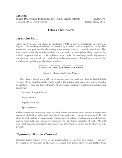
Reverberation
1961Artificial
(‘Colorless”
Logan:
and Schroeder
209
center speaker, the absence of a hole in the middle becomes a rare“specialcase”forperhapsjustoneobserving location and perhaps not even one location.
This is true regardless of the stereo recording technique or number of microphones. No bridging of microif there is no
phonescan fill theholeinthecenter
speaker there to reproduce it except sometimes for one
unique observing location. The center speaker
is capable
of affording the “solid sound curtain.”
nearest speaker. Thus, toe-in accomplishes its function
evenwithonlytwospeakers.
The principle has to do with projecting more sound
energy toward the opposite side
of the listening area.
A natural(‘floodlight”spatialradiationpattern
is desirable--the “spotlight”patternwouldbe
fatal-and
of suitablelistening
thetoe-in for thebastmajority
roomsbecomes
45’.
The center speaker is still necessary. Combined with
toe-in of flanking units, the error figures‘l derived for a
V I I I . TOE-IN
central listening position were of the order of 0.12 and
increased to 0.16 for observersat the flanksof the listenSlightlylaterthanthefamedSymposium,Snow
off and the toe-in
showed the desireability to angle or ((toe-in” the outside ing area. .With the center speaker
speakers.EJ2The effect is toreducetheshift
of the eliminated, the error was 0.62. For the spacings used,
a “live” error figure of 0.04 obtained. Error figures for
virtual sound sources for different observing locations,
thus supplementing the function of the center speaker. three independent channels and for the two channels
withbridgedcenterspeakerdifferedbyinsignificant
Evenpriortotherevival
of thebridgedcenter
amounts.
speaker, this writer advocated corner speaker spacing
and toe-in for stereo.13T h e effect was to enable listeners
IX. CONCLGSION
a t the flanks to hear stereo, but listeners at
all points
The requirements of good audio and good stero may
experienced the hole in the middle. The virtual sound
be summed up in the eight cardinal points.
sources remained a t one side or the other. But without
Largebookscouldbewrittenonthesepoints.The
thetoe-in,thelistenerontheflankheardonlythe
foregoing is an attempt to touch the high spots, while
affordingsomebasicbib!iographyforonewhowould
18 P. IV. Klipsch, “Experiences in stereophony,” Audio, vel. 39,
delvefurther.
pp. 16-17, 41-42; J L I ~ Y1955.
,
“Colorless” Artificial Reverberation*
M. R. SCHROEDERf AND B. F. LOGAN?,
MEMBER, IRE
Summary-Electronic devices are widely used to introduce in
simple to achieve, unless one uses a reverberation cham
sound signals an artificial reverberation subjectively similar to that
ber or the electrical equivalent
of a three-dimensiona
caused by multiple reflections in a room. Attention is focused
on
space.
Reverberation
chambers
(and
plates1) areprethose devices employing delay loops. Usually, these devices have a
ferred
by
broadcast
stations
and
record
manufacturers
comb-like frequency response which adds an undesired “color” to
because of their high quality and lack
of undesirable
the sound quality. Also, for a given reverberation time, the density
of echoes is far below that encountered in a room, giving rise to a
side effect, but they are not truly
arti$cial reverberators.
noticeable flutter effect in transient sounds.A class of all-pass filters
In this paper, we shall focus our attention on
elecis described which may be employed in cascade to obtain “colorless”
tronic
reverberators
consisting
of
delay-lines,
disk
or
reverberation with high echo density.
E
tape-delay, and amplifiers. Electronic reverberators are
both cheaper than real rooms and have wider applicability, notably in the home (unless one wants to convert the basement intoa reverberation chamber). They
can also be employed to increase the reverberation time
of auditoriums, thereby adapting them to concert hall
use, without changing the architecture.
* Received by the PGA, December 8, 1960; revised manuscript
received,February 27, 1961. Reprintedwith permission fromthe
J . Audio Engrg. Soc., vol. 9, pp. 192-197; July, 1961.
t Bell Telephone Labs., Inc., Murray Hill, N.J .
W. Kuhl, “The acollstical and technological properties
of the
reverherationplate,” European Broadcas!ing L‘n.ion Rev., Pt. ATechnical, No. 19;May, 1958.
INTRODUCTION
L E C T R O N I C devices are widely used todayto
add reverberationtosound.Ideally,suchartificial reverberatorsshouldactonsoundsignals
exactly like real, three-dimensional rooms. This is not
TRANXACTIONX
IRE
210
Beforeattemptingthedifficulttask
of reproducing
room characteristics by delal--lines, i t is wise t o recall
some of the important propertiesof large rooms.
THEFREQ-CEXCY
RESPONSE
O F LARGER o o m
room can be characterized by its normal modes
of
vibration. It has been shonrn2 that the density of modes
is nearly independent of room shape and is proportional
t o the squareof the frequency:
number of modes per cps
Here V = thevolume,
=
(;)y.
c = thevelocity
OlV AC‘DIO
November-December
THE TRASSIENT
BEHAVIOR
OF ROOMS
H o w does a room respond to excitation with a short
impulse? If we record the sound pressure at somelocation in the room as a function of time, \x-e first observe
an impulse corresponding to the direct sound which has
traveledfromthesoundsourcetothepick-uppoint
without reflection at the malls. A4ftert h a t we see a number of discrete lon--order echos which correspond to one
or a few reflections at the walls and the ceiling. Gradually, the echo density increases to
a statistical “clutter.” I n fact, it can be shown’ that the echo density is
proportional to the square of the elapsed time:
of sound,and
f the frequency.
number of echos per second
Above a certain critical frequenc~-,~ given by
~-
J c = 2 0 0 0 d T / V (reverberation time T i n seconds, V inm”,
the density of modes becomes so high that many modes
overlap. In this frequency range, whichis of prime interest for large rooms, the concept
of individual normal
modes loses its practical (though not its theoretical) significance. T h e behavior of the room is governed by the
collectiveaction of man>-simultaneouslyexcitedand
interferingmodesresultingin
a very irregular amplitude-frequency r e ~ p o n s e . ~However,
,~
thefluctuations
are so rapid (on the frequency scale) that the ear, in
listening to a non-steady sound, does not perceive these
irregularities.6 (The response fluctuations can be heard
by exciting the rooms with a sinen-ave of slowly varying
frequency and listening with one ear.) \Vhen the room
response is measuredusing,instead
of asinewave,a
psychoacousticall>-moreappropriatetestsignal,such
as narrow bands of noise, the response would indeed be
much smoother.
I t is this apparent smoothness of a room’s frequency
response x\-hich people have found particularly difficult
to imitate with artificial reverberators. In this paper we
shall describe electronic reverberators which have perfectly flat amplitude-frequencyresponses.Thus,they
not only overcome this long-standing difficulty but are
actually superior to roomin this one respect.
Hen-ever, a flat frequenc~, response is not the onl?,
requirement for a high-quality reverberator. Before we
can hope to successfully design one, we must also know
something about the transient behavior of rooms.
2 P. 41. hlorse
and
I<. H , Bolt,
“Sound
\vaves in
Rev.
J f a d . Phys., vol. 16, pp. 69-150: April, 1944.
3 M. R. Schroeder,“Die$atistischenParameterderFrequenzjurven von grossenRaumen,
Acz~stica,vol. 4, Beiheft 2 , pp. 594600; 1954.
4 E. C. \Vente, “Characteristics oi sound transmission in rooms,”
J . Acaust. Soc. A m . , vol. 7 , pp. 12$!26; October, 1935.
5 13. Kuttruffund
R. ThiFle,UberdieFrequenzabhangigkeit
desSchalldruclrsimRkumen,
A c ~ ~ ~ t ivol.
c a 4,
, Beiheft 2 , pp. 614617; 1954.
6 A . F. Sickson and R. IV. Muncey, “Frequency irregularity in
rooms,” Acustica, vol. 5,pp. 44-48; 1955.
4TC3
= ___ 1 2 .
1‘
The time after which the echo response becomes
;L
statistical clutter depends on the width
of the exciting
impulse. For a pulse of width At, the critical time after
which individual echos start overlapping is about
t,
=
5 .I
O - ~ (V
~inIm3).
~Z
‘Thus, for transients of I-msec duration and a volunle
of 10,000 1n3(350,000 ft3), the response is statistical for
times greater than 150 msec. In this region, the concept
of theindividualecho
loses itspracticalsignificance.
T h e echo response is determined by the collective behavior and interference of many overlapping ethos.*
a4notherimportantcharacteristic
of large“diffuse”
rooms is t h a t allmodeshavethesameornearlythe
same reverberation time and thus decay at equal rates
as evidenced by a straight-line decay when plotting the
sound level in decibels vs elapsed time.
Still another property of acoustically good rooms is
theabsence of ‘(flutter”echos, ie., periodicechosresulting from sound waves bouncing back and forth between parallel hard walls. Such periodicities in the echo
responsearecloselyassociatedwithone-dimensional
modes of sound propagation which can be avoided by
splaying the walls and placing “diffusors” i n the sound
path.
T H EC O N D I T I O S S TO BE ~ I E TH Y
ARTIFI(:I;\L REVERBERATORS
Afterthis brief review,wearein
a positioll t o t‘ormulate conditions to be met by artificial reverberators.
1) T h e frequency response must be flat when measured with narrow bands of noise, the bandwidth corresponding to thatof the transients in the sound to bereverberated. This condition is, of course, fulfilled b y re7 L. Crenler,“Diev-issenschaftlichenGrundlagenderRaumakustik,” Band 1 (“Geometrische Raumaltustilc”), S. Hirzel I’erlag,
Stuttyart, Germany, vol. 1, p. 2 7 ; 1948.
* R. C. Jones, “Theory of fluctuations in the decay of sound,”
J . ..lcoz~st. Sor. A v z . , vol. 11, pp. 324-332; Januar:,, 1940.
1961
21 1
“Colorless”
Logan:
ArtiJicial
Schroeder
Reuerberation
and
verberators which have a flatresponseevenforsinusoidal excitation.
2) The normal modes of the reverberator must overlap and cover the entire audio frequency range.
3) The reverberation times of the individual modes
must be equal or nearly equal
so that different frequency
components of the sound decay with equal rates.
4) The echo density a short interval after shock excitation must be high enough
so that individual echos
are not resolved by the ear.
5 ) The echo response must be free from periodicities
(flutter echos).
In addition to these five conditions, a sixth one must
be met which is not apparent from the above review of
room behavior but easily violated by electronic reverberators :
6) Theamplitude-frequencyresponsemustnot
exhibit any apparent periodicities. Periodic or comb-like
frequencyresponses
produceanunpleasanthollow,
reedy, or metallic sound quality and give the impression
that the sound is transmitted through a hollow tube or
barrel.
This condition is a particularly important one because
long reverberation times are achieved by circulating the
sound by means of delayinfeedbackloops.Theresponses of such loops, which are the equivalent of onedimensional sound transmission, are inherently periodic
andspecialprecautionsarerequiredtomakethese
periodicities inaudible.
Inthe following, a basicreverberator is described
which fulfills conditions l ) , 3) and 6) ideally.Byconnecting several of these reverberating elements in series,
conditions 2 ) , 4) and 5) canalsobesatisfiedwithout
violating the others.
TWOSIMPLE
REVERBERATORS
Thesimplestreverberatorconsists
of a delay-line,
disk, or tape-delay which gives a single echo after a delay time 7 . Its impulse response is
h(t) = 6 ( t -
(1)
T),
GAIN, g
(a)
1 / ~
2/r
FREQUENCY, f
(c>
Fig. 1-(a) Delay in feedback loop. (b)Impulseresponse.(c)Frequency response. Simple reverberators with exponentially decayinc echo response. Frequency response resembles comb.
The corresponding complex frequency response is
H ( w ) e--iw7 + ge-2iwr + g 2 e - 3 i w ~ + . . . ,
(4)
or, using the formula for summing geometric series,
e- i w
H(u) = ~ _ _ _
(5)
1 - ge-i.ur
T
-
By taking the absolute square of H ( w ) , one obtains
the squared amplitude-frequency response:
i
I H(w) l2
=
1
+ g2 - 2g cos w7
(6)
1
As can be seen, H(w)1 is no longer independent of frequency. In fact, for w = 2 n ~ / (rn = 0 , 1, 2 , 3, * ), the
response has maxima (for positive g) given by
e
H,,,,
1
=-
1-g
(7)
where s ( t ) is the Dirac delta-function (an ideal impulse).
and, for w = (2n+1)7r/7, minima given by
The spectrum of the delayed impulse is
H(w)
=
e--iwr,
(2)
1
H,,i, = -.
l + g
(8)
where w is the radian frequency. The absolute value of
H(w) is one. This means that all frequencies are passed
The ratio of the response maxima to minima is
equally well and without gain or loss.
I f g
Inordertoproducemultipleechoswithout
using
H m a x l H m i n = -*
(9)
more (expensive) delay, one inserts the delay line into a
1-g
feedback loop, as shown in Fig. 1, with gain g of magniFor a loop gain of g = 0.7 ( - 3 db), this ratio is 1.7/0.3
tude less than one (so that the loop will be stable). The
impulse response, illustrated in Fig. l(b), is now a n ex- =5.7 or 15 d b !
Theamplitude-frequencyresponse
of a delay in a
ponentiallydecayingrepeatedecho:
feedback loop has the appearance of a comb with perih ( t ) = 6(1 - 7)
g6(t - 27)
g%(t - 37)
‘ ’ *
( 3 ) odic maxima and minima, as shown in Fig. l (c). Each
+
+
+
OJY A U D I O
TRALVXACTIONS
IRE
212
responsemaximumcorrespondstoonenormalmode.
The natural frequencies are thus spaced 1 / T cps apart.
The 3-db-bandwidth of each peak is approximately
- lng
(10)
Ai=-----,
X7
~V:ouembe.r-Decemher
T h e corresponding frequency response is
p-
tu 7
or
where “111” denotes
the
logarithm
the
to
base
e = 2 . 7 1 8 . . . Convertingtologarithmstothebase
10 (log), one obtains
Aj =
1
~
2 0 log
~ e
or
-Y -Y
- 0.0367
>
~
7
7
(1 1)
where y is the loop gain in decibels:
y = 20 log g. For
y = - 3 db, the bandwidth is about 0.1117 or only one-
ninth of the spacingof the natural frequencies. The sub- What is the absolute valueof this H ( w )? T h e first factor
on the right has, of course, absolute value one. The secjective effect of this resonant response is the hollow or
ondfactor is the quotient of twoconjugatecomplex
reedy sound quality mentioned above.
vectors, i.e., its absolute value is also one. Thus,
A L I . - P A S S REVEKBEKATOHS
In our search for better reverberators, we discovered
t h a t a certain mixture of the output of the multiply delayedandtheundelayedsoundresultedinanequal
response of thereverberator forallfrequencies.
The
mixingratiothataccomplishesthisandresultsin
unity gain for all frequencies is (-g) for the undela>,ed
sound and (1 -g’) for the multiply delayed sound. The
correspondingcircuit is shown in Fig. 2 . Its impulse
response is givenby
h(t) = - g6(f)
+ (1 - g’)
+ g6(t - 27) + . I.
. [ 6 ( t - 7)
‘
*
1 H(w) 1
=
1.
(16)
In other words, the addition of a suitably proportioned
undelaped path has converted the comb filter
(6) into
an all-pass filter (16). This is not a mere academic result. The conversion of a combfilterintoanall-pass
filter is accompanied by a marked improvement of the
sound quality from the
hollowsound of the former to
the perfectly “colorless” quality of the latter.
Now we are in possession of a basic reverberating element which passes all frequencies with equal gain and
thus fulfills conditions 1) and 6) above. The spacings and
decay rates of the normal modes (thoughno longer “visible” as resonant peaks of the amplitude-frequency response)arethesameasthoseforthepreviouslydiscussed comb filter. Thus, condition
3), requiring equal
decay rates for the normal modes, is also fulfilled.
Whetherthenormalmodesoverlap(condition
2)
can no longer be judged on the basis
of the amplitudefrequency response because it is constant. However, the
phase-frequency response still reflects the distributionof
normal modes and thus must conform to condition
2).
T h e phase-lag of N(w) asafunction
of frequencyis,
with (15) ,
A more convenient quantity to consider
is the rate of
change of phase-lag with respect to radian frequency:
whichhasexactlythesamedependenceon
w asthe
squareamplitude-frequencyresponse
H ( w ) of the
corresponding comb filter [see (6) 1. T h e physical significance of d+/do is t h a t of the envelope or “group” delay
of a narrow band of frequencies around w. According to
1
Fig. 2-(a) ;\ll-pass filter. (b) Impulseresponse. (c) Frequencyresponse.XIodification of simplereverberator. B y adding proper
amount of undelayed signal, frequency response of reverberator
becomes flat (all-passreverberator).
I
1961
Reverberation
Arti$cial
“Colorless”
Logan:
Schroeder and
(18), for a loop gain of g = 0.7 this envelope delay fluctuates as much as 32:1 for different frequency bands, with
the long delays occurring,of course, for frequencies near
the natural frequencies, 2 m , / T ( n= 0 , 1, 2 , * . . ), of the
filter. The half-width of the envelope delay peaks is the
same as that for squared amplitude [see (10) 1. Thus,
for a loop gain of - 3 db, only one-ninthof all frequency
components suffer a large envelope delay, while the remaining frequencies are much less delayed. This constitutes a very unequal treatment of different frequency
components and violates condition 2).
The remaining two conditions, 4) and 5 ) , are also violated as we shall see immediately. The relationship between reverberation time T (defined by a 60-db decay)
and the two parameters of the reverberator, the delay T
and the loop gain y in decibels, is as follows. For every
trip around the feedback loop the sound
is attenuated
y db. Thus, the 60-db decay timeis
60
T=-Y
213
matical details of this peculiar reverberation because he
has suffered already too much, we are afraid.
Fig. 4 showstheimpulseresponse
of fiveall-pass
filtersconnected in series with loop delays
of 100, 68,
60, 19.7, 5.85 msec. Theloopgainsare
+0.7, -0.7,
+0.7, +0.7, +0.7, respectively. This combinationof delays and gains was arrived at after considerable experimentation observing the response toa variety of sounds,
both on the oscilloscope and by listening, and using
a
smooth envelope of the decay as a criterion. The appearance of the echo response is quite random and not
unlike that of real rooms.11x12An increase i n pulse density with increasing time can also be noticed.
T
For y = - 3 d b , 9 we have T=2O.r. Thus, i n order to
achieve, for example, 2 seconds of artificial reverberation,theloopdelaymustbe
0.1 sec.Withthisloop
delay the basic reverberating element shown
in Fig. 2
produces one echo every one-tenth
of a second. Thisconstitutes a most undesirable periodic flutter echo. Also,
the echo density (ten echos per second) is much too low
to give a continuous reverberation. Thus, conditions 4)
and 5) are violated.
How can one obtain a less periodic time response and
agreater echo density without giving up the all-pass
characteristic?’” If several all-pass feedback loops with
incommensurate loop delays are connected in series, as
illustrated in Fig. 3, the combined frequency response
remains flat, while the echo response becomes aperiodic
and the echo density increases.
In addition, a better coverage
of the frequency axis
withnormalmodes
is achieved.Infact,theenvelope
delay response of the series connection is a sum of terms
like (18) withdifferent r ’ s . Sinceeach of theseterms
‘(covers” only one-ninth of the frequency axis, at least
five all-pass feedback loops in series are required. On the
other hand, one can also show that
too many all-pass
feedback loops in tandem are bad because they lead to
a very unnatural, nonexponential reverberation which
builds up to its maximum intensity rather slowly before
i t starts decaying. We shall spare the reader the mathe1Ve do not consider open-loop gains greater than
0.7 (-3 db),
because in practice it is difficult to maintain the desired closed loop
characteristics with gainstoo close to unity.
Io N. V. Franssen,‘*SeuentwicklunginderraumlichenSchallwiedergabe,” Bericht uher die
4. Tonmeistertagung, netmold, Gcrmany; October, 1957, p. 10; Frenssen has suggested the use of multia flatopen-loopfreple feedback, proportioning thegains to give
quencyresponse.This
allows larger loop gainswithoutincurring
instability. However, a feedback loop around an all-pass filter results
in anonflatfrequencyresponse,
unless supplementedby a direct
path of suitable gain as described above.
Fig. 3-Series connection of several all-pass reverberatorswith
commensurate delays to make echo response aperiodic and increase echo density.
in-
of five
Fig. 4-Echo
response of all-passreverberatorconsisting
simple reverberators connected in series, as shown in Fig. 3.
E. Meyer and R. Thiele, “IZaumalrustische Untersuchungen in
zahlreichenKonzertsalenundRundfunlcst~tdiosunterAnwendung
neuererMessverfahren,” Acz~stica,vol. 6,Reiheft 2, pp. 425-444;
1956.
I2 G. R. Schodder,“UberdieVprteilungderenergiereicheren
Schallriickwurfe in Salen,” Acustica, vol. 6, Beiheft 2, pp. 445-465;
1956.
214
T R AIN
RSEA C T I O N S
DIGITAL
COMPUTER
SIMULATION
O N AUDIO
November-December
but nevertheless easily perceptible. We have overcome
this disadvantage by using a pair of all-pass filters, like
the one shown in Fig.2 , to split thesingle-channel audio
signal.Thisidea
is describedingreaterdetail
in a
forthcoming publication.16
T h e impulse response shown in Fig.
4 was obtained
from a large digital computer (IBll 7090) in conjunction with special digital-to-analog conversion and plotting apparatus. In addition to using the computer as a
“draftsman,” many of the actual reverberation experiSL~MlLlRY
ments were performed with the help of the digital comSeveral reverberators of the all-pass type were sucputer. In this research method (sometimes called “digicessfully
simulated on a digital computer (IBM 7090).
tal sim~lation”~~), ordinary (“analog”) tape recordings
Others
were
instrumentedwithdelay-linesandtapeof the sound to be reverberated are prepared and condelay.
No
coloration
of the reverberation sound was deverted into digital tapes by means of special conversion
tected
in
any
of
these
electronic reverberators. Our lisequipment. The computer then reads the digital tape
tening
experience
with
all-pass
reverberators indicates
andactsuponitexactlylikeanydesiredrealequipthat
the
problem
of
unequal
response
to different frement would act on the sound signal.
T o facilitate the
quencies
has
been
solved
and
sound
“coloration”
comprogramming of the computer, our engineers make use
pletely
eliminated.
Audible
flutter
echos
have
been
of a special translation program, developed a t Bell Teleavoided by the use of severalall-passfeedback
loops
phoneLaboratories,whichtranslatestheirblockdiawith
“incommensurate”
delays
in
series.
grams into the computer language. Thus, the computer
The application of all-pass reverberators to the probfirst “compiles”itsownprogramonthebasis
of the
lem
of increasing the reverberation time of auditoriums
block diagram information and then acts
on the sound
and
concert
halls by purely electroacoustic means17 reastheblockdiagramwoulddo.
It then prepares one
mains
to
be
studied.
Here the flat frequency response i s
(orseveral)digitaloutputtapeswhichareconverted
particularly
important
for two reasons: 1) I t minimizes
backintoanalogtaperecordingsandevaluatedby
acoustic
feedback
problems.
The
“ringing”andinlistening.Needlesstosay,this
is a verypowerfulrestability
due
to
the
unavoidably
irregularfrequency
searchtool,especiallywhencomplexequipment
is t o
response
of
the
room
can
be
reduced by shifting all frebe evaluated! In this manner we have studied the subquency
components
of
the
reverberated
soundby
a
jective quality of a great variety of reverberators with
small
constant
2)
A
flat
response
of
the
reboth flat and nonflat frequency responses.
verberatorcontributestothehighsoundqualityrequired in concert hall applications. 1Jltirnate acceptance
APPIJCATION TO QUASI-STEREOPHONY
of
electroacoustic techniques in concert halls and opera
Thelate
HolgerLauridsen14
of theDanishState
houses
is assuredonly if the artificialeffectsare
not.
Radiohasdiscovered
a method of splitting a single
recognized
as
such
by
the
music-loving
public.
audio signal into two “quasi-stereophonic” signals which
givethelistenerallthe“ambience”
of multichannel
stereophony but permits, of course, no correct localization of individualsoundsources.Inordertoachieve
this, Laurid’sen has used delay networks connected to
form a pair of interleaved comb filters.’j However, these
combfiltersgiverisetounpleasantsoundqualitiesnotquiteaspronouncedasinartificialreverberators,
l 3 E. E. Da\;jd,Jr.,
“Lligitalsimulation inresearch on human
communication, PROC.IRE, vol. 49, pp. 319-329; January, 1961.
H . Lauridse;: “Sogle fors&
med
forsicellige former rum
akustikgengivelse, Ingenibren, no. 47, p. 906; 19.54.
M. R. Schroeder, “An artificialstereophonic effect obtained
from a single audio signal,” J . Audio Engrg. Soc., vol. 6, pp. 74-79;
AApril,1958.
ACKNOKLEDGMENT
IVe thank 1Iiss X. Kordahlforassistanceinthe
computersimulationexperimentsandMessrs.
A. J.
Prestigiacoma, F.K. Harvey and J . G. Cisekforconducting a variety of auxiliary experiments.
16 31. R . Schroeder,“Improvedquasi-stereophonyandrolorless
artificial reverberation,” J . A c o u s t . Soc. Aim., vol. 33, pp. 1061-1064:
A4ugust,1961.
17 R. Vermeulen,“Stereoreverberation,”
J . A u d i o Engrg. S o c . ,
vol. 6, pp. 124-130; .April, 1958.
l * A I , R. Schroeder, “Stop feedback i n pubiic address systems,”
Radio Electronics, vol.31,
pp. 40-42; February, 1960.
Seealso
inpublicaddress
“Improvement of acousticfeedbackstability
systems,” Proc. 3rd Intunail. Congr. 44coustics, ElsevierPublishitlg
Co.. Amsterdam, The Setherlands, vol. 2 , pp. 771-775; 1961.


© Copyright 2026