
LP SolidStart Laminated Strand Lumber and Laminated Veneer
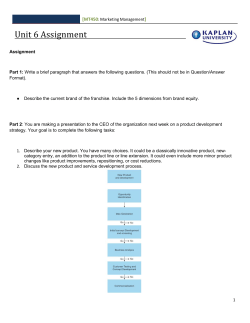
LP® SolidStart® Laminated Strand Lumber and Laminated Veneer Lumber Louisiana-Pacific Corporation PR-L280 Revised April 3, 2015 Products: LP SolidStart 1.35E, 1.55E, and 1.75E LSL LP SolidStart 1750Fb-1.3E LVL Rim Board LP SolidStart 2250Fb-1.5E, 2400Fb-1.7E, 2650Fb-1.9E, 2900Fb-2.0E, 2950Fb-2.0E, 3100Fb-2.1E, and 3100Fb-2.2E LVL LP Building Products, Louisiana-Pacific Corporation, 414 Union Street, Suite 2000, Nashville, Tennessee 37219 (615) 986-5600 [email protected] www.lpcorp.com 1. Basis of the product report: • 2015 International Building Code (IBC): Sections 104.11 Alternative materials and 2303.1.10 Structural composite lumber • 2012, 2009 and 2006 IBC: Sections 104.11 Alternative materials and 2303.1.9 Structural composite lumber • 2015 International Residential Code (IRC): Sections R104.11 Alternative materials, and R502.1.5, R602.1.5, and R802.1.4 Structural composite lumber • 2012, 2009 and 2006 IRC: Section R104.11 Alternative materials, and 2012 IRC Sections R502.1.7, R602.1.4, and R802.1.6 Structural composite lumber • ASTM D5456-14b, Standard Specification for Evaluation of Structural Composite Lumber Products • ASTM D5456-13, ASTM D5456-09, ASTM D5456-05a and ASTM D5456-03 recognized by the 2015 IBC and IRC, 2012 IBC and IRC, 2009 IBC and 2006 IBC, respectively • APA PRR-401 Performance Standard for APA EWS Rim Boards • PFS Corporation Test Reports (Louisiana-Pacific Corporation, Golden, BC): 1750Fb 1.3E, 2250Fb - 1.5E Douglas-fir LVL, 2250Fb - 1.5E Lodgepole pine LVL, 2650Fb - 1.9E Douglas-fir LVL, 2650Fb - 1.9E Lodgepole pine LVL, 2950Fb - 2.0E Douglas-fir LVL • APA Reports T2005P-76A, T2006P-06, T2006P-25A, T2006P-26, T2007P-89, T2008P10, T2008P-13, T2008P-31, T2008P-39, T2008P-43, T2008P-46A, T2008P-49A, T2008P-55, T2008P-66, T2008P-85, T2008P-86, T2008P-94A, T2008P-106B, T2008P112, T2008P-113A, T2009P-04B, T2009P-05, T2009P-12, T2009P-13, T2009P-25, T2009P-26, T2009P-64, T2009P-84, T2010P-14, T2010P-16, T2010P-18, T2010P-19, T2010P-24, T2010P-25, T2011Q-14A, T2011P-24, T2011P-30, T2011P-68, T2012P-08, T2012P-20, T2013P-15, T2013P-17, T2013P-19, T2014P-16, T2014P-26A, T2014P-27A, T2014P-28, T2014P-48, and other qualification data 2. Product description: 2.1 LP SolidStart Laminated Strand Lumber (LSL) LP SolidStart LSL is made with strands of various species and strand classifications in accordance with the in-plant manufacturing standard approved by APA. The LSL may be treated with an EPA-registered zinc borate for decay and termite resistance to a retention level equivalent to that specified in American Wood Protection Association (AWPA) Standard T1-13 for Use Category 2 (UC2). When treated, the LSL is designated as LP SolidGuard™ LSL. For the purposes of this report, the designations of LP SolidStart LSL and LP SolidGuard LSL can be used interchangeably. © 2015 APA – The Engineered Wood Association 05-06 APA Product Report PR-L280 Revised April 3, 2015 Page 2 of 11 LP SolidStart LSL is available with thicknesses up to 5-1/4 inches, and a range of widths and lengths. Refer to the manufacturer’s technical guide (http://www.lpcorp.com/resources/literature/) and a local LP Engineered Wood Products distributor for product availability. LP SolidStart LSL can also be used as wall framing in conventional light-frame construction of the applicable code and in engineered wall systems. The minimum thickness of the LSL for wall framing is 1-1/2 inches. LP SolidStart LSL may be used as rim board with a minimum thickness of 1-1/8 inches. 2.2 LP SolidStart Laminated Veneer Lumber (LVL) LP SolidStart LVL is made with wood veneers laminated with grain parallel to the length of the member in accordance with the in-plant manufacturing standard approved by APA. LP SolidStart LVL is available with thicknesses up to 3-1/2 inches, and a range of widths and lengths. LP SolidStart LVL “Billet Beams” are fabricated by face-laminating primary thicknesses, and are available in thicknesses of 3-1/2, 5-1/4 or 7 inches. Refer to the manufacturer’s technical guide (see link above) and a local LP Engineered Wood Products distributor for product availability. LP SolidStart LVL having a grade of 1.5E or greater can also be used as wall framing in conventional light-frame construction of the applicable code and in engineered wall systems. The minimum thickness of the LVL for wall framing is 1-1/2 inches. LP SolidStart LVL Rim Board is LP LVL with two or more veneers oriented 90 degrees (cross-ply) to the length. LP LVL Rim Board is available with a minimum thickness of 1-1/4 inches, and may be used for all applications applicable to LP LVL except wall framing. 3. Design properties: Table 1 lists the design properties, Table 2 lists the equivalent specific gravities for fastener design, Table 3 lists the allowable loads for rim boards, and Table 4 lists the allowable nail spacing for LP SolidStart LSL and LVL. 3.1 Beams, headers, and columns: The allowable loads for LP SolidStart LSL and LVL beams, headers, and columns shall be in accordance with the recommendations provided by the manufacturer (see link above). 3.2 Wall framing: 3.2.1 Prescriptive Stud Wall Applications: LP SolidStart LVL having a grade of 1.5E or greater, and LP SolidStart LSL used as studs in conventional construction are permitted in accordance with Sections 2308.5.9 and 2308.5.10 of the 2015 IBC, Sections 2308.9.10 and 2308.9.11 of the 2012/2009/2006 IBC, and Section R602.6 of the 2015 through 2006 IRC. 3.2.2 Engineered Stud Wall Applications: LP SolidStart LVL having a grade of 1.5E or greater, and LP SolidStart LSL shall be permitted in engineered wall applications when designed based on net section analysis in accordance with the National Design Specification for Wood Construction (NDS) and the restrictions specified in Section 4.3.2. The allowable design stress for bending, axial compression, and axial tension shall be multiplied by the strength reduction factors in Table 5 to account for stress concentrations in notches and holes. The allowable shear values for nailed wood structural panel shear walls using LP SolidStart LVL having a grade of 1.5E or greater, and LP SolidStart LSL as the wall studs © 2015 APA – The Engineered Wood Association 05-06 APA Product Report PR-L280 Revised April 3, 2015 Page 3 of 11 shall be determined using Table 2306.4.1 of the 2006 IBC where the LP SolidStart LSL and LVL shall be considered to be equivalent to sawn lumber studs with a specific gravity of 0.50, when subjected to the nailing restrictions specified in Section 4.3.3 of this report. 4. Product installation: 4.1 Beams and headers: LP SolidStart LSL and LVL shall be installed in accordance with the recommendations provided by the manufacturer (see link above). Permissible details and allowable hole sizes shall be in accordance with the recommendations provided by the manufacturer. 4.2 Columns: 4.2.1 LP SolidStart LSL and LVL used as free-standing columns shall not be drilled or notched without the approval of a professional engineer or the manufacturer. Bolts, lag screws, and self-tapping screws shall only be inserted through the face of the column, perpendicular to the face of the strands in LP SolidStart LSL and the veneers in LP SolidStart LVL. 4.2.2 Built-up columns: When used for built-up columns, LP SolidStart LSL and LVL shall be constructed using connections specified by the manufacturer (see link above). 4.3 Wall framing: 4.3.1 Prescriptive stud wall applications: Cutting, notching and boring of LP SolidStart LVL having a grade of 1.5E or greater, and LP SolidStart LSL used as studs in conventional construction is permitted in accordance with Sections 2308.5.9 and 2308.5.10 of the 2015 IBC, Sections 2308.9.10 and 2308.9.11 of the 2012, 2009, and 2006 IBC, and Section R602.6 of the 2015 throigh 2006 IRC. Stud wall nailing restrictions and requirements are presented in Section 4.3.3 of this report. 4.3.2 Engineered stud wall applications: Cutting, notching and boring of LP SolidStart LVL having a grade of 1.5E or greater, and LP SolidStart LSL shall be permitted in engineered wall applications with the following restrictions: a) Holes up to 40% of the stud depth are allowed anywhere in the stud height for bearing walls, except that a hole shall not be placed within 6 inches of either end of the stud. A minimum edge distance of 5/8 inch shall be maintained for all holes for stud depths of 5-1/2 inches (i.e., nominal 2x6) or less. For larger depths, a minimum edge distance of 12% of the stud depth shall be maintained for all holes. b) Notches up to 25% of the stud depth are allowed anywhere in the stud height, except that a notch shall not be placed within 6 inches of either end of the stud. The notch length shall not exceed 8 inches. c) Holes and notches shall not be cut at the same cross section, and the minimum clear vertical space between hole and notch shall be 2 times the hole diameter or 2 times the notch length, whichever is greater. d) Stud wall nailing restrictions and requirements are presented in Section 4.3.3. 4.3.3 Stud wall nailing restrictions and requirements a) LP SolidStart LSL Studs • For sheathing attached with 10d common nails (0.148 inch x 3 inches) with a spacing no closer than 6 inches on center, a single LP SolidStart LSL stud shall be permitted for framing at adjoining panel edges. Nails shall be installed a minimum 3/8 inch from all panel edges. • For sheathing attached with 8d common nails (0.131 inch x 2-1/2 inches) or smaller with a spacing no closer than 4 inches on center, a single LP SolidStart © 2015 APA – The Engineered Wood Association 05-06 APA Product Report PR-L280 Revised April 3, 2015 Page 4 of 11 LSL stud shall be permitted for framing at adjoining panel edges. Nails shall be installed a minimum 3/8 inch from all panel edges. • For sheathing attached with 8d common nails (0.131 inch x 2-1/2 inches) spaced closer than 4 inches on center or 10d common nails (0.148 inch x 3 inches) spaced closer than 6 inches on center, a double, stitch-nailed, LSL stud or single 2-1/2 inch thick LSL stud is required at adjoining panel edges. Nails shall be installed a minimum 3/8 inch from all panel edges and shall be staggered a minimum of 1/4 inch for each row of nails. b) LP SolidStart 1.5E or greater LVL Studs • For sheathing attached with 8d common nails (0.131 inch x 2-1/2 inches) or smaller with a spacing no closer than 6 inches on center, a single LP SolidStart LVL stud shall be permitted for framing at adjoining panel edges. Nails shall be installed a minimum 3/8 inch from all panel edges. 10d common nails (0.148 inch x 3 inches) are not allowed where a single LP SolidStart LVL stud is used at adjoining panel edges. • For sheathing attached with 10d common nails (0.148 inch x 3 inches) spaced no closer than 4 inches on center or 8d common nails (0.131 inch x 2-1/2 inches) spaced no closer than 3 inches on center a double, stitch-nailed, LVL stud or single 2-1/2 inch thick LVL stud is required at adjoining panel edges. Nails shall be installed a minimum 1/2 inch from all panel edges and shall be staggered a minimum of 1/4 inch for each row of nails. c) For stud wall applications in accordance with the IRC and the conventional lightframe construction provisions of the IBC [Sections 2308, Table 2304.10.1 (2015 IBC), and Table 2304.9.1 (2012, 2009, and 2006 IBC)], double LSL and LVL studs shall be stitch-nailed together with 2 staggered rows of nails (minimum 0.120 inch x 2-7/8 inches) spaced 8 inches in each row. For engineered stud wall applications, the stitch nailing of double LSL and LVL studs shall be designed to transfer the required lateral shear using an assumed equivalent specific gravity of 0.50. d) Nails shall not be spaced closer than 3 inches on center. e) Maximum nail size is 10d common (0.148 inch x 3 inches). 4.4 4.4.1 5. Rim board: LP SolidStart LSL or LP SolidStart LVL rim boards shall be installed in accordance with the recommendations provided by the manufacturer (see link above) and the code. Fire-rated assemblies: 5.1 The provisions of Section 722.6.3 of the 2012 IBC or Section 721.6.3 of the 2009 and 2006 IBC, design of fire-resistant exposed wood members, shall be applicable to LP SolidStart LSL and LVL when used as a bending member (beam and header). Fire-rated assemblies shall be constructed in accordance with the recommendations provided by APA Fire-Rated Systems, Form W305 (www.apawood.org/resource-library), and the manufacturer. 5.2 When used as joists/rafters, LP SolidStart LVL having a grade of 1.5E or greater, and LP SolidStart LSL are permitted to be used as direct replacement for solid-sawn lumber having the same dimensions, in any fire-resistance-rated floor/roof assemblies listed in Table 721.1(3) of the 2015 and 2012 IBC or Table 720.1(3) of the 2009 and 2006 IBC. 5.3 The provisions of Section R302.13, Exception 4 of the 2015 IRC and Section R501.3, Exception 4 of the 2012 IRC for fire protection of floors shall be applicable to floor assemblies constructed with LP SolidStart LVL having a grade of 1.5E or greater, and LP © 2015 APA – The Engineered Wood Association 05-06 APA Product Report PR-L280 Revised April 3, 2015 Page 5 of 11 SolidStart LSL with a nominal 2x10 dimension (i.e., 1-1/2 inches by 9-1/4 inches net dimension) or greater. 5.4 When used as wall studs, LP SolidStart LVL having a grade of 1.5E or greater, and LP SolidStart LSL are permitted to be used as a direct replacement for solid-sawn lumber of No. 2 or lower grades, having the same dimensions, in any fire-resistance-rated wall assemblies listed in Table 721.1(2) of the 2015 and 2012 IBC or Table 720.1(2) of the 3 2009 and 2006 IBC. A minimum of 2.5 lbf/ft mineral wool insulation shall be placed in the stud cavity. 5.5 As an alternative to the prescriptive fire-resistance-rated wall assemblies listed in Table 721.1(2) of the 2015 and 2012 IBC or Table 720.1(2) of the 2009 and 2006 IBC, a onehour fire-resistance-rated wall assembly shall be permitted to be designed and constructed with the limitations listed below, provided that the applied axial stress on each stud does not exceed 440 psi for 1.75E and 1.55E LP SolidStart LSL, 380 psi for 1.35E LP SolidStart LSL, and 550 psi for LP SolidStart 1.5E or greater LVL. When the slenderness ratio exceeds 33, the Fc’, which is the Fc|| value tabulated in Table 1 for each stud grade adjusted for all applicable adjustment factors, including column stability factor, in accordance with NDS, shall be multiplied by 0.77 for LP SolidStart LSL and 0.63 for LP SolidStart LVL having a grade of 1.5E or greater. a) The stud spacing shall be no greater than 24 inches on center, b) The top and bottom plates of the wall shall be constructed in accordance with the nailing schedule specified in Table 2304.10.1 of the 2015 IBC, Table 2304.9.1 of the 2012, 2009, and 2006 IBC or Table R602.3(1) of the 2015 through 2006 IRC. c) The wall shall be covered with one layer of 5/8-inch Type X gypsum wall board attached to studs with 2-1/4-inch long Type S drywall screws at 7 inches on center on the perimeter and in the field, and 3 d) A minimum of 2.5 lbf/ft mineral wool insulation shall be placed in the stud cavity. Exception: For the purpose of one-hour fire-resistance-rated wall assemblies, 1.75E LP SolidStart LSL shall be designed using the properties of, and subjected to the same limitations as 1.55E LP SolidStart LSL. 6. Limitations: a) LP SolidStart LSL and LVL shall be designed in accordance with the code using the design properties and installation requirements specified in this report. b) LP SolidStart LSL and LVL is limited to dry service conditions where the equivalent moisture content of sawn lumber is less than 16 percent. c) LP SolidStart LSL is produced by Louisiana-Pacific Corporation facility in Houlton, Maine under a quality assurance program audited by APA. e) LP SolidStart LVL is produced at the Louisiana-Pacific Corporation facilities in Wilmington, North Carolina, Golden, British Columbia, Canada and the Murphy Engineered Wood Division facilities in Sutherlin, Oregon under a quality assurance program audited by APA. A list of the LVL grades manufactured at different LP and Murphy facilities is maintained by APA for independent auditing purposes. d) This report is subject to re-examination in one year. 7. Identification: The LP SolidStart LSL and LVL described in this report are identified by a label bearing the manufacturer's name (Louisiana-Pacific Corporation) and/or trademark, the APA assigned plant number (1092 for the Houlton plant, 1071 for the Wilmington plant, 1066 for the Golden plant, and 1089 for the Sutherlin plant), the product type and grade, the APA logo, the report number PR-L280, and a means of identifying the date of manufacture. © 2015 APA – The Engineered Wood Association 05-06 APA Product Report PR-L280 Revised April 3, 2015 Page 6 of 11 Table 1. Design Properties (Allowable Stress Design) for LP SolidStart LSL and LVL LP SolidStart LVL Rim Board LP SolidStart LSL Property 1.35E 1.55E 1.75E 1750Fb1.3E 2250Fb1.5E 2400Fb1.7E 2650Fb1.9E 2900Fb2.0E 2950Fb2.0E 3100Fb2.1E 3100Fb2.2E 1,730(d) 2,360(d) 2,500(d) 1,750(e) 2,250(f) 2,400(f) 2,650(f) 2,900(f) 2,950(f) 3,100(f) 3,100(f) (g) (g) (g) (g) (g) (g) 2,950(g) (i,j) 1,800(I,j) Plank 1,910 (h) Tension parallel to grain (Ft), psi Longitudinal shear (Fv), psi Modulus of Elasticity (E), 106 psi 2,620 (h) 2,800 (h) 1,750 (j) 2,200 (i,j) 2,300 (j) 2,600 (i,j) 2,950 (i,j) 2,950 (i,j) 3,100 1,300 1,750 2,100 1,200 1,350 1,350 1,600 1,800 1,800 1,800 Joist 410 410 410 250 285 285 285 285 290 290 Plank 155 155 155 140 140 140 140 140 140 140 140 1,650 2,175 2,450 1,700 2,350 2,350 2,350 3,200 3,200 3,200 3,200 750 875 950 680 750 750 750 750 750 750 750 Compression parallel (Fc||), psi Compression perpendicular (Fc⊥)(m), psi LP SolidStart LVL (cross-ply) Joist Bending (Fb)(c), psi (a,b) Joist Plank 685 775 890 Joist 1.35(k) 1.55(k) 1.75(k) 1.30(k) 1.50(k) 1.70(k) 1.90(l) 2.00(k) 2.00(l) 2.10(k) 2.20(k) (k) (k) (k) (k) (k) (k) (l) (k) (l) (k) 2.20(k) Plank 1.35 1.55 1.75 450 290 1.30 1.40 550 1.70 1.80 2.00 2.00 2.00 For SI: 1 inch = 25.4 mm, 1 foot = 304.8 mm, 1 lbf = 4.448 N, 1 psi = 6.9 kPa. (a) (b) (c) (d) (e) (f) (g) (h) (i) (j) The tabulated values are design values for normal duration of load. All values, except for E and Fc⊥, are permitted to be adjusted for other load durations as permitted by the code. The design stresses are limited to conditions in which the equivalent moisture content of sawn lumber does not exceed 16 percent. Allowable stresses for “Joist” refer to loads applied parallel to the wide face of the strands (the edge of the member). “Plank” refers to loads applied perpendicular to the wide face of the strands (the face of the member). Tabulated flexural stress (Fb) may be increased by 4 percent when the member qualifies as a repetitive member as defined in the NDS. The tabulated values for LP SolidStart LSL are based on a reference depth of 12 inches. For other depths, when loaded edgewise, the allowable bending stress (Fb) shall be modified by (12/d)0.143. For depths less than 3-1/2 inches, the factor for the 3-1/2-inch depth shall be used. The tabulated value for LP LVL Rim Board (with cross plies) is based on a reference depth of 12 inches. For other depths, when loaded edgewise, the allowable bending stress (Fb) shall be modified by (12/d)0.261. For depths less than 3-1/2 inches, the factor for the 3-1/2-inch depth shall be used. The tabulated values for LP SolidStart LVL are based on a reference depth of 12 inches. For depths greater than 12 inches, multiply Fb by (12/d)0.143. For depths less than 12 inches, multiply Fb by (12/d)0.111. For depths less than 3-1/2 inches, the factor for the 3-1/2-inch depth shall be used. For LP SolidStart LVL “Billet Beams” up to 7 inches in thickness (see Section 2.2), the allowable bending stress (Fb) in plank orientation shall be modified by (1.75/d)0.25 ≤ 1.0. The tabulated values for LP SolidStart LSL are based on a reference length of 3 feet. For other lengths, the allowable tensile stress shall be modified by ( 3 / )0.092, where = length in feet. For lengths less than 3 feet, use the allowable tension stresses in Table 1 unadjusted. For LP SolidStart LVL 1-1/2 inches in thickness, the allowable tension parallel to grain (Ft) is as follows: LP SolidStart LVL Grade 2250Fb-1.5E 2650Fb-1.9E 2900Fb-2.0E and higher Ft (1-1/2-inch-thick LVL) 1,750 1,875 2,100 The values for LP SolidStart LVL published in Table 1 and Footnote (i) are based on a reference length of 3 feet. For other lengths, the allowable tensile stress shall be modified by (3/ )0.111, where = length in feet. For lengths less than 3 feet, use the allowable tension stresses in Table 1 or Footnote (i) unadjusted. © 2015 APA – The Engineered Wood Association 05-06 APA Product Report PR-L280 Revised April 3, 2015 (k) Page 7 of 11 The tabulated modulus of elasticity is the shear-free MOE. For uniformly loaded simple-span beams deflection is calculated as follows: 270 w L4 28.8 w L2 δ= Where: δ L b = = = E b h3 estimated deflection, inches, span, feet, beam width, inches, and + Ebh w E h = = = [Eq. 1] uniform load, plf tabulated modulus of elasticity, psi beam depth, inches (l) The tabulated modulus of elasticity is the apparent MOE, which includes the effects of shear deformation. When calculating deflection, standard engineering formulae for pure bending deflection are sufficient, and the second term of Equation 1 in Footnote k may be ignored. (m) When designing with the tabulated compressive stress perpendicular to grain (Fc⊥), the Bearing Area Factor (Cb) stipulated in Section 3.10.4 of the NDS shall be permitted to be applied. © 2015 APA – The Engineered Wood Association 05-06 APA Product Report PR-L280 Revised April 3, 2015 Page 8 of 11 (a,b,c) Table 2. Fastener Design for LP SolidStart LSL and LVL Equivalent Specific Gravity (S.G.) (a) (b) (c) (d) (e) (f) (g) Nails Nails and Wood Screws Withdrawal Load Lateral Load Installed in Edge Installed in Face 0.46 0.50 0.46 0.50 0.46(f) 0.50 Installed in Edge Installed in Face LP SolidStart LSL 0.50 0.55 LP SolidStart LVL Rim Board (cross-ply) 0.50 0.50 LP SolidStart LVL 0.50 0.50 Bolts and Lag Screws(d,e) Lateral Load Installed in Face Parallel Perpendicular to Grain to Grain 0.50 0.58 0.46 0.50 0.46(g) 0.50 Fastener types and orientation not specifically described above are beyond the scope of this report. Fastener design values calculated using the tabulated equivalent specific gravities given above must be adjusted by the applicable adjustment factors specified in the NDS for connections. Fastener spacing, and end and edge distances must be as specified in the NDS, except that nail spacing and end distance must be as specified in Table 4. Bolts and lag screws shall only be installed into the face (plank orientation) of the LSL and LVL. The capacities for 1/2" (12.7 mm) diameter lag screws installed into LP SolidStart LSL and LVL Rim Board for ledge attachment shall be in accordance with Table 3. The equivalent specific gravity value is permitted to be increased to 0.49 for LVL manufactured from the Sutherlin plant (Mill number 1089) in accordance with APA PR-L283. The equivalent specific gravity value is permitted to be increased to 0.50 for LVL manufactured from the Sutherlin plant (Mill number 1089) in accordance with APA PR-L283. Table 3. Allowable Loads for LP SolidStart LSL and LVL Rim Boards Grade 1730Fb-1.35E and above 1750Fb-1.3E 1.5E and above Thickness (in.) Lateral Load(b,c) (lbf/ft) Vertical Uniform Load(d) (lbf/ft) Depth ≤ 16” < Depth 16” ≤ 24”(e) LP SolidStart LSL 1-1/8 200 4,850 NA 1-1/4 250 6,000 3,800 ≥ 1-1/2 280 7,000 4,500 LP SolidStart LVL Rim Board (cross-ply) ≥ 1-1/4 250 9,350 5,070 LP SolidStart LVL 1-1/2 ≤ t <1-3/4 250 4,000 2,500 t ≥ 1-3/4 250 4,500 3,450 (a) Vertical Concentrated Load (lbf) Depth ≤ 24”(e) Lateral Resistance for 1/2- inch-dia. Lag Screws (lbf) 3,500 3,800 4,500 400 450 475 4,210 450 2,700 3,200 450 450 For SI: 1 inch = 25.4 mm, 1 foot = 304.8 mm, 1 lbf = 4.448 N, 1 lbf/ft = 14.6 N/m. (a) (b) (c) (d) (e) The tabulated lateral load capacity is based on the short-term load duration (10 minutes). The vertical uniform and vertical concentrated load are not permitted to be adjusted for any load durations. Toe-nailed connections are not limited by the 150 lbf/ft lateral load capacity noted for Seismic Design Categories D, E and F in Section 2305.1.4 of the IBC. The nailing schedule for sheathing to rim and rim board to sill plate (toe-nailed) is based on 8d box (0.113” x 2-1/2”) nails at 6 inches on center (refer to APA W345, APA Performance Rated Rim Boards® for full details). Commercial framing connectors may be used to achieve lateral load capacities exceeding the values shown in this table. Calculations shall be based on the equivalent specific gravity values listed in Table 2 subjected to the nailing spacing provided in Table 4. The allowable vertical uniform load capacity is based on the strength of the rim board and may need to be reduced based on the bearing capacity of the supporting wall plate. 1-1/8-inch thick LP SolidStart LSL is limited to a maximum depth of 16 inches for rim board applications. © 2015 APA – The Engineered Wood Association 05-06 APA Product Report PR-L280 Revised April 3, 2015 Page 9 of 11 (a,b) Table 4. Minimum Allowable Nail Spacings for LP SolidStart LSL and LVL Thickness (in.) Orientation(e) Edge(h) 1” ≤ t < 1-1/4” Face(i) Edge(h) 1-1/4” ≤ t < 1-1/2” Face(i) Edge(h) 1-1/2” ≤ t < 1-3/4” Face(i) Edge(h) ≥ 1-3/4” Face(i) Edge(h) < 1-1/2” Face(i) Edge(h) ≥ 1-1/2” Face(i) Common Nail Minimum End Size(f,g) Distance (in.) LP SolidStart LSL 8d & smaller 2 10d & 12d 2 16d NA(j) 8d & smaller 7/8 10d & 12d 7/8 16d 7/8 8d & smaller 2 10d & 12d 2 16d 2-1/2(k) 8d & smaller 7/8 10d & 12d 7/8 16d 7/8 8d & smaller 2 10d & 12d 2 16d 2-1/2(k) 8d & smaller 7/8 10d & 12d 7/8 16d 7/8 8d & smaller 2 10d & 12d 2 16d 2-1/2(k) 8d & smaller 7/8 10d & 12d 7/8 16d 7/8 LP SolidStart LVL 8d & smaller 2-1/2 10d & 12d 2-1/2 16d 3-1/2 8d & smaller 1-1/2 10d & 12d 1-1/2 16d 1-1/2 8d & smaller 2-1/2 10d & 12d 2-1/2 16d 3-1/2 8d & smaller 1-1/2 10d & 12d 1-1/2 16d 1-1/2 Minimum Nail Spacing per Row (in.) Single Row Multiple Rows (c,d) 4 4 NA(j) 1 1 1-1/2 4 4 5(l) 1 1 1-1/2 3 3 4 1 1 1-1/2 3 3 3 1 1 1-1/2 4 4 5 3 3 5 3 4 5 3 3 5 NA 1 1 1-1/2 NA 1 1 1-1/2 3 4 6 1 1 1-1/2 3 4 6 1 1 1-1/2 NA 3 3 5 4(m) 5(m) 6(m,n) 3 3 5 For SI: 1 inch = 25.4 mm. (a) (b) (c) (d) (e) (f) (g) (h) (i) (j) (k) Spacing requirements and maximum nail size for panel edge nailing of wall sheathing at adjoining panels must be in accordance with Section 4.3.3. Edge distance shall be sufficient to prevent splitting. Multiple rows must be spaced 1/2 inch or more from each other and offset one-half of the tabulated minimum nail spacing, as shown in Figure 1. Multiple rows must be equally spaced about the centerline of the edge or face (whichever applies). Face orientation applies to nails driven into the face of the LSL or LVL member, such that the long axis of the nail is perpendicular to the wide faces of the strands or veneers. Edge orientation applies to nails driven into the edge of the LSL or LVL member. 16d sinkers (0.148” x 3-1/4”) may be spaced the same as a 12d common wire nail (0.148” x 3-1/4”). Nails listed are common wire nails. For box nails, the spacing and end distance requirements of the next shorter common nail may be used: e.g., a 16d box nail may be spaced the same as a 10d and 12d common nail. Larger nail sizes and shank types not specifically described above are beyond the scope of this report. Nail penetration for edge nailing shall not exceed 2 inches for 16d common nails (0.162” x 3-1/2”) and 2-1/2 inches for all nails with a smaller shank diameter. Tabulated closest on-center spacing for face orientation is applicable to nails that are installed in rows parallel to the grain (length) of the LSL or LVL. For nails installed in rows perpendicular to the direction of grain (width/depth) of the LSL or LVL, the closest on-center spacing for face orientation shall be sufficient to prevent splitting of the LSL or LVL. For LSL thicknesses of 1-1/8 inches or greater, 16d common nails (0.162” x 3-1/2”) are permitted to be driven into the edge, with a minimum end distance of 2-1/2 inches and a minimum spacing of 5 inches. For LSL thicknesses less that 1-1/8 inches, 16d common nails (0.162” x 3-1/2”) are not permitted to be driven into the edge. Minimum end distance may be reduced to 2 inches when the nail penetration into the edge of the LSL does not exceed 1-3/8 inches. © 2015 APA – The Engineered Wood Association 05-06 APA Product Report PR-L280 Revised April 3, 2015 (l) (m) (n) Page 10 of 11 Minimum end distance may be reduced to 4 inches when the nail penetration into the edge of the LSL does not exceed 1-3/8 inches. Minimum nail spacing is tabulated for LVL manufactured from the Sutherlin plant (Mill number 1089). The minimum nail spacing may be reduced by 1 inch for LVL manufactured from the Wilmington and Golden plants (Mill numbers 1077 and 1066). Minimum nail spacing may be reduced by 1 inch for 1-3/4-inch thick (or greater) LVL manufactured from the Sutherlin plant (Mill number 1089). Offset S/2 1/2” Min. Between Rows Symmetric About Centerline Nail Spacing (S) per Row Figure 1. Spacing of multiple rows of nails. Table 5. Strength Reduction Factors for Notches and Holes in LP SolidStart LSL and LVL (a,b,c) Studs Material LP LSL LP LVL (a) (b) (c) Bending 0.95 0.80 Notches Compression 0.90 0.90 Tension 0.75 0.60 Bending 1.00 0.95 Holes Compression 1.00 0.95 Tension 1.00 0.95 Design of LP LSL and LP LVL studs with notches and holes used in engineered wall framing must be based on a net-section analysis in accordance with the NDS. See Section 4.3.2 of this report for limitations on the allowed size and placement of notches and holes. The reference design stresses for bending, compression and tension from Table 1 must be multiplied by the strength reduction factors in the above table. See Section 4.3.1 for notching and boring of holes in LP LSL and LP LVL studs used in prescriptive wall framing. © 2015 APA – The Engineered Wood Association 05-06 APA Product Report PR-L280 Revised April 3, 2015 Page 11 of 11 APA – The Engineered Wood Association is an approved national standards developer accredited by American National Standards Institute (ANSI). APA publishes ANSI standards and Voluntary Product Standards for wood structural panels and engineered wood products. APA is an accredited certification body under ISO/IEC 17065 by Standards Council of Canada (SCC), an accredited inspection agency under ISO/IEC 17020 by International Code Council (ICC) International Accreditation Service (IAS), and an accredited testing organization under ISO/IEC 17025 by IAS. APA is also an approved Product Certification Agency, Testing Laboratory, Quality Assurance Entity, and Validation Entity by the State of Florida, and an approved testing laboratory by City of Los Angeles and Miami-Dade County. APA – THE ENGINEERED WOOD ASSOCIATION HEADQUARTERS 7011 So. 19th St. ▪ Tacoma, Washington 98466 Phone: (253) 565-6600 ▪ Fax: (253) 565-7265 ▪ Internet Address:www.apawood.org. PRODUCT SUPPORT HELP DESK (253) 620-7400 ▪ E-mail Address: [email protected] DISCLAIMER APA Product Report is a trademark of APA – The Engineered Wood Association, Tacoma, Washington. The information contained herein is based on the product evaluation in accordance with the references noted in this report. Neither APA, nor its members make any warranty, expressed or implied, or assume any legal liability or responsibility for the use, application of, and/or reference to opinions, findings, conclusions, or recommendations included in this report. Consult your local jurisdiction or design professional to assure compliance with code, construction, and performance requirements. Because APA has no control over quality of workmanship or the conditions under which engineered wood products are used, it cannot accept responsibility for product performance or designs as actually constructed. © 2015 APA – The Engineered Wood Association 05-06


© Copyright 2026