
HERE - Palomar Engineers
2238
DIG I T A L
FREQUENCY
MODEL
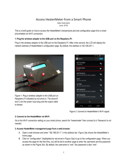
DISPLAY PD-SOO INSTALLATION INSTRUCTIONS HEATHKIT MODEL HW-10l P A LO MAR
E NGINEER S PD-SOO DIGITAL FREQUENCY DISPLAY Purpose. Many of the classic radios of the 1960's arid 1970's are . still in use. They work well and sound good. The newer modern rigs have many "bells and Whistles", a lot of them not really useful. But they do have one very important improvement: a digital readout . . The PD-SOO Digital Frequency Display adds this valuable feature to your older rig.
Description. PD-SOO works with transceivers that have three
oscillators in their heterodyne scheme. One usually a crystal
oscillator, another a VFO or variable frequency oscillator, and
the other a fixed frequency "carrIer . oscillator" . Three cables
bring these signals to the Digital Display where, in two mixers,
the exact operating frequency is regenerated. This Is displayed
on a six digit numerical readout.
Installation. The three cables that bring the signals to the
Digital Readout are provided. They plug into the rear of the
readout: Black pI ug into the CARRIER OSC socket, Red plug into
the INJ socket, and qrey plug into the C socket. A separate
Instruction manual
showing the cable
connections to
the
transceiver is provided for your particular transceiver model.
A DC supply of 10-14 volts at 200 milliamperes is required.
It connects to a 2.Smm socket on the rear panel. A matIng plug
is provided. The shell is negatIve; the tip is positive. DC power
pack cubes (such as the Palomar PS-90) which plug directly into
an AC outlet work well.
Operation. Set the TUNE knob to point straight up (12 o'clock
position) and the BAND MHz switch to the band the transceiver is
9n. SlIde the power swItch to oftl and the dIsplay should light up.
If the display does not lockup firmly adjust the TUNE knob unt;il
it does.
.
The TUNEknohmakes possible operatiOn on any frequency from
1.5 to 40 . MHz. For the amateur bands that are marked on the
bandswitch this control usually can be left in the straight up
position.
The primary function of the TUNE control is for operating on
frequencies other than the bands marked on the bandswitch. For
example, to use the readout on the 18 MHz band set the bandswitch
to 14 and turn the TUNE control in the + direction . until the
display locks in. To tune for the 12 MHz broadcast band (if your
rig is general coverage) set the bandswitch to 14 and turn the
TUNE control in the - direction until the display locks in.
PALOMAR ENGINEERS
P.O. Box 462212, Escondido, California,
U~S.A.
2
CABLE INSTALLATION - HEATHKIT MODEL HW-IOl
1. Three cables are provided. Each has a 39-pf disc capacitor on
one end and a color coded plug on the other. The plugs go to the
PO-BOO Digital Readout. The capacitors connect to the HW-I01.
2. First, find or make a way for the cables to
interior and to exit from the enclosure.
get to the HW-lOl
3. Connect the capacitor of the cable with the red plug to pin 7
of VI2 on the Bandpass Circuit Board (see pictorial). Ground the
shield to any convenient ground point.
The connections can be
made across R223 (see schematic).
4. Connect the capacitor of the cable with the grey plug to pin 7
of ViI on the RF Driver Circuit Board (see pictorial). Ground the
shield. The connections can be made across R407.
5. Connect the capacitor of the cable with the black plug to pin
3 of V16 on the Modulator Circuit Board (see pictorial).
Ground
the shield.
The connections can
be made across R9
(see
schemat ic) .
6. Reassemble the HW-IOl enclosure.
7. Plug the cables
into the PO-BOO Digital Readout.
Black plug into CARRIER OSC socket.
Red plug into INJ socket.
Grey plug into C socket.
8. Refer to the "PO-800 Installation
operating instructions.
and operating Manual"
for
J
CIRCUIT BOARD X-RAY ·VIEWS (viewed from foil side)
To CARRIER OSC
Black Plug
MODULATOR CIRCUIT BOARD
To INJ
Red Plu g
BANDPASS CIRCUIT BOARD
·.=:.
,
~, "
',0 ' ';
;;'ii,;,;Lr~~,':';i~~~:~,~~:;j,:'~~;:.,
6408
C414:J
:......
~404
C4t3~
...... C4Z2A
~<-~_:~~::..::
:;" ','(~ ;,. "
;'J.
! ..
, :d~:-:;'
-ill.1]}
t-.1'.
@,
,.'.:'C'42ze
\C~o' :
4 I
..-c~17
~'
1 T
,~
,
.t
' ®~
C403
W.~ '
1R~
~
C419
'
~
" ::illIDCC416
0 V"G
--lli1QIJ
To
"e" Grey Plu g .' ~
".,'
~lS
. ....:.
' ;' C421A
---oiQL
-c5-407
-
-
-®Q1}
RF DRIVER CIRCUIT BOARD
1
:
C
'0
o
'::
o
ON FOIL 51
5
SCHEMATIC
HW-l0l
To
r
'
,_... ~:i-> - 2-T~
" i
_...........
-_ ........
J ", ." "----''-- .
~'I
?-:.;~~:\O::,~ ':~: :
-= ;=7
I
"...,.;ol"~"
,
I'
,
I
~:r ':' 1:», I
~ :;r;"~::;_
I
:L!~;;:'~i
~
I
:
k::-
I
=
•
I.'
=
V1e
o ..
~
o
SCHEMATIC
HW-l0.1
,,
I
:::'~---::f-"-----+--+=='----__-t-.J
L _________ _
-
-
-
-- -
-
-
-
-
-
-
-
-
-
-
-
-
-
-
-
7"
~!~-.
,
, n
,.
14
!
I
i
vn
I
".\' I
..~,~'(.,.!·I
[l
l''' :
To INJ
Red
Plug
i
!
" , 'f
i
""''':''r-!
., .. ,.
---------~
__ I
.,
,•
.
§~;~,.1:~
~ 'i
I
~~
.. .
------------.., ., "
• , f<E1 T :;;'.A. :
';~;);,
'¥"!}C:l
I
: ~~~ :
: A~
• .,.. I ' .
! I I
;."~2i' ~'if:
:": I"~_:_'''I~
" '.~;'
J : ~.'~
'-/K'- " ' .",,'
• T .,....
:
;~ ~
-:..~ 2"""~
=
:
*"1 ~,, ; : ~=I i ~~'."
_--====-'=' '='-=-=-=- ='"-=-'=-'=- =: : '"-==~-:j'L=:'- " ~=''=- -=''=1-='='-='~'lJiif'
,
="
'=
'-
i : ~
.
-::=:;
Cal"
r a»
y
~
. . ~~
. ". ,"
-.'
A
HW-101 SCHEMATIC
r -".,"'"
J[___
___ :
------ - _. -------
,
, ,
... __ _ -, . ....'i.- --' -
-J
~r I
---------------fy----------------~----~---------------_-_-_-_-_-_-_-~-~~--------~'-~1__+~~~~---·-~JL-=~~i-"!fi~
----~rr--------~~
r"
i
yll
}--- - -- - -r-- - -;-
!
!
VtO
... ".
I
:~.~"~:
:;: ~I
..
.rr.
~
.. _
..=- .
..k;- 't..... .....
'r · O"~Jol. (
I
.I
I
L
- -
=
-
.,.,
I
:
II
i
i
--.....--t- ~:J
I
~ ..
* !
I
To
Grey
"e"
Plu ~
- - T
-
- - -
-
,
;r - - - -..,.. - - - -
,
.' .: ®'-' :®
.,' " ~
.,
":$"
:
...
.@
.
..
.
.
~
:
.
-0
.
~
,..,
'
:
"
).
. ,
''
,,'
.....
. .. " . ,
,",
.,
)
..
).,
....
"
I
•
. . ,
.J
/ ~
""
, ""'
,
..
~.
~
>0
" 1""\ .
.
u
., .,
-I
o
SCHEMATIC
HW-10l
iI
j)A"O ••
• '.1.
11
~II,
I
.
' " 14
\l14e
i
I
vu
Itft,'
iI
"ft
rn
I»(C [· ... I,.A
To INJ
Red Plug
I;
~.-
,~
' ::~.I-2
y
.
",.,
... .
,.. '
.....
.
.. ,.
.-. -----
±~;).1~~
~
~
"..
r 'f '~ '-'('l . $ ~
.
,
_,
_4
•
•
'3" ' i -'3"
... ..
-..-, - ------ -.- '
1.10 •• , •
.
~~)Ai)
;
. ~"'=~:
_ _ _ _ .....
____
..L_
e
eM. · OSC.
.
NOTE ~ L-68uH tor
"
Colll.nI~
.
.
.
.
~
.
:~
.J . .
. I\PFH!12
+
.. 1
. HUJ · . Z
3
c
.• .( ;h...
'±:¢
.1
1
L4 .
1
. LSS2I
L2
S
faa
1
r
112Jfl . 2
~
...
4
1496 1J
5
IB
6
11
s·
9
41"B .
.
~5V
La
.---...... COlMER
. .1
. 15BB
OK) t.a
------~----~ CCU4TER
T
"'V'"
11110
1.B
. BJ ·
3.5
8M[)
. fIPF 11112
5VITCH
l~
FRCtIT PANa.. .·
.
IBB
raE·
'--._-._-.......::.:........ uH
21
P~L{)/,\J'\R
D
(J:)D
"PF102
TIP
E
. VIEV ·
~~"0c
. ZNS18 .
·Et£INEERS
2220
12-92 . .
f\IXER
PO-600 DIGITAL DISPLAY
. ~ . ...
4640 LSO ·· I\SO
TCP..
140 1
l~o 2
·12
04
1
1
2
6
.-q
B
CD
.,
IS)
0 '7
REAR
1
2.
6
8
8
13
14
.14
.,
13. . "'1".
14
4 · 9
.<:> 6.
2
6
IS)
.~
7'
. c.o
13
'T
L
2
6
£Sl
B
(D
13
14
'T
.,
1
2
6
~.
4 · f!
4
fSl
"'f
LD
r
8
13
~
14
4
9
9
VIEV
4?'
+5V
47K
It
T PI9
41"
9
727
6 123
800 Hz
7208
S21"O.8
28 -- . . . . . . . . .. 140 __-----:.----tt---'-'-~-'_____,
11 .. ;· ·· ······13b
QH
~5 ...... .." ... ~~
~.
. .
~6 :::::'.'.' :~;
KHz. .
18 ;. ;.. : .... , '2Ql 4
12
:3
•
~7'
.
1 •~
1l.l~
4 • 1~
~~ .....,..-2--1r4LS 195
8 .
RESET
. 01
. 1NPlIT~
DIVIDE BY 10
0 I V I DE BY 2
1---II~.:.r~............~;.....c13--f? 45 11 4 j-;;5=-----;-;;;L...~
2192
5 -92
.REV. A
Frequency Counter
PD-700
DIGITAL DISPLAY
2-93


© Copyright 2026