
Broadband Wireless Access WISP Cookbook June 2003
Broadband Wireless Access
WISP Cookbook
June 2003
Error! No text of specified style in document.
ISP Cookbook
ii
Legal Rights
Legal Rights
© 2003 by Alvarion Ltd. All rights reserved.
No part of this publication may be reproduced in any material form
without the written permission of the copyright owner.
Trade Names
Alvarion®, BreezeACCESS®, BreezeCOM®, BreezeLINK®,
BreezePHONE®, BreezeNET®, WALKair®, WALKnet®, are trade names
or trademarks of Alvarion Ltd. Other brand and product names are
trade names or trademarks of their respective owners.
Manual Revision
i
Introduction
This document is aimed to satisfy the needs of the Internet Service
Providers industry for comprehensive information on Broadband
Wireless Access (BWA). It is intended for ISPs who are looking at BWA
as an alternative to traditional wire- or cable-based services, including:
a. An established ISP that considers adding BWA to its infrastructure
for one or more of the following reasons:
Expand coverage to new customers-either in an already served area
or in new areas.
Provide services in rural and other areas where wireless access is
the only viable option.
Enhance its services portfolio to improve competitive position and
increase revenues and profits.
Eliminate expenses, delays and long-term commitments associated
with getting access services from a third party.
b. A new entrant to the rapidly evolving ISP market place wishing to
benefit from the advantages of a business based on BWA.
Regardless of the reasons for becoming interested in BWA, there are
numerous questions that must be answered, related to various crucial
issues that must be considered prior to taking the decision to invest in
a BWA based network, while launching a new BWA network and
throughout the life time of the network.
We at Alvarion have been working closely with global telecom and
Internet operators over a long period of time. A wide range of
professionals in Alvarion – senior management, sales force, customer
service and technical staff – have met a long list of Operators’
management, operations and technical teams. They have discussed
challenges together, made errors together, fixed problems together and
succeeded together.
Introduction
Alvarion professionals have gathered years of experience and know-how,
witnessing Operators’ experiences, preferences, challenges and
difficulties concerning many facets of their overall network.
Our staff has accumulated a large set of testimonials regarding our
partners’ network build-out. What they saw related to various aspects of
the network and to various types of networks. Over time, we witnessed
a wide range of situations experienced by our partners: from the
management decision-making process to technical and logistic activities
by different types of operators: cellular, data access, ISPs and local
independent telcos.
Until now, this valuable information has not been shared in any
integrated, comprehensive format. Moreover, we began to notice that
different operators often faced identical challenges. Unaware of their
predecessors’ experience, they often repeated the same mistakes.
In the meantime, a number of Alvarion employees have, over time,
witnessed a recurrence of questions and problems among our many
customers. The questions may be directly related to the Alvarion
solution, or may be directed to overall network challenges.
We have assembled all the information gathered from the field into a
comprehensive format that shows the big picture while recalling the
small details.
This overview refers to all the aspects concerning a BWA project, from
backbone interfaces, to integrated network solutions at the customer
site; from the NAT location debate to management system
considerations; from VoIP to billing; it discusses technology pros and
cons as well as business models.
This document offers you a comprehensive overview of our accumulated
knowledge in order to help you understand all the important aspects of
BWA and assess the project you are taking or about to take. The
document has been divided by subject matter, so that you can skip to
read only the areas that are relevant to you, or read its entirety whichever fits you best.
We urge you to look for more information on specific issues in other
sources available through your Alvarion representative. We also invite
you browse our material-wealthy website at www.alvarion.com.
ISP Cookbook
ii
Introduction
It must be emphasized that many applicable issues vary significantly
among countries and even regions. These includes issues such as local
regulations that affect technical considerations and issues that affect
the business model such as the competitive landscape, labor cost,
customers’ profile etc. You are invited to consult with our experts in
order to reach the right conclusions and build the business plan that
takes into account all the unique aspects of becoming a Wireless ISP in
your target area.
Manual Revision
iii
Contents
Chapter 1 - Wireless Access Systems Basics .......................................1-1
Licensed and unlicensed frequencies ...................................................... 1-2
Spread Spectrum Radio Technologies...................................................... 1-3
Industry Standards ................................................................................. 1-4
IEEE 802.11................................................................................................. 1-4
IEEE 802.16................................................................................................. 1-5
Chapter 2 - Wireless Access System Architectures ..............................2-1
Sectorized Cellular Architecture ............................................................. 2-2
Micro-cellular Architecture ..................................................................... 2-5
Cell Extension ........................................................................................ 2-5
Chapter 3 - Customer Types ....................................................................3-1
Introduction ........................................................................................... 3-2
MDU/MTU Customers ............................................................................. 3-2
Residential MDUs......................................................................................... 3-2
Commercial MTUs ........................................................................................ 3-3
Hospitality segment...................................................................................... 3-3
SME Customers ...................................................................................... 3-4
SOHO Customers .................................................................................... 3-4
Residential Customers ............................................................................ 3-5
Law Enforcement and Public Safety Agencies .......................................... 3-6
Chapter 4 - Services .................................................................................4-1
Contents
General.........................................................................................................4-2
Best Effort Service .....................................................................................4-2
What is Quality of Service? ........................................................................4-2
Service Level Agreement (SLA)....................................................................4-2
Why is QoS required?.................................................................................4-3
Methods for providing QOS ........................................................................4-3
QoS Network Architectures ........................................................................4-4
IEEE 802.1p Prioritization ............................................................................4-5
VLANs ..................................................................................................... 4-7
IP services at the CPE ............................................................................. 4-8
NAT ..............................................................................................................4-8
DHCP ...........................................................................................................4-8
DHCP Server..............................................................................................4-9
DHCP Client ..............................................................................................4-9
DHCP Relay Agent .....................................................................................4-9
Firewall.......................................................................................................4-10
DMZ (Demilitarized Zone).........................................................................4-10
Port Filtering............................................................................................4-10
SPI (Stateful Packet Inspection)................................................................4-10
WAN Filtering...........................................................................................4-11
Routing services at the CPE ........................................................................4-11
Dynamic Routing .....................................................................................4-11
Static Routing ..........................................................................................4-11
VPN (IPsec) .................................................................................................4-11
PPPoE ................................................................................................... 4-12
Introduction ...............................................................................................4-12
How does PPPoE work?...............................................................................4-13
Some deployment considerations ................................................................4-14
Chapter 5 - Business Case Analysis ...................................................... 5-1
The Market Model: Segments, Services and Revenues ............................. 5-4
The Costs................................................................................................ 5-5
Capex ...........................................................................................................5-5
OpEx ............................................................................................................5-6
The Financial Plan .................................................................................. 5-7
What you need to know before you start.................................................. 5-8
Example Scenarios ................................................................................ 5-11
Business Only - Suburban..........................................................................5-14
ISP Cookbook
ii
Contents
Residential Only - Suburban ...................................................................... 5-17
Mixed Residential & Business - Suburban.................................................. 5-20
Chapter 6 - Alvarion’s BWA Solutions Summary...................................6-1
BreezeACCESS Product Line ................................................................... 6-2
Base Station Equipment............................................................................... 6-3
Modular Base Station Equipment .............................................................. 6-4
Stand Alone Access Unit............................................................................ 6-4
Miniature Access Unit ............................................................................... 6-4
Cell Extender ............................................................................................... 6-4
Customer Premise Equipment (Subscriber Units) ......................................... 6-5
Indoor-Outdoor SU-A/E Subscriber Units ................................................. 6-5
Miniature SU-I Subscriber Units ............................................................... 6-5
Small Foot-Print SU-R Subscriber Units .................................................... 6-5
Subscriber Unit’s Capabilities ................................................................... 6-5
WALKair 1000......................................................................................... 6-7
Base Station................................................................................................. 6-8
Terminal Station ........................................................................................ 6-11
WALKair 3000....................................................................................... 6-12
BreezeNET DS.11 and DS.5800 ............................................................. 6-14
The Base Unit ............................................................................................ 6-14
The Remote Bridge ..................................................................................... 6-14
BreezeACCESS LB ................................................................................. 6-15
System Components................................................................................... 6-15
Management Systems ................................................................................ 6-15
Supplementary Equipment Available From Alvarion .............................. 6-16
BreezeACCESS RG 2-Ports Voice Gateway.................................................. 6-16
BreezeSECURE Broadband VPN Router ..................................................... 6-17
BreezeACCESS TM Traffic Manager ............................................................ 6-18
Chapter 7 - Connectivity to Backbone Networks ...................................7-1
Backbone Networks................................................................................. 7-2
ATM Backbone Networks.............................................................................. 7-2
Scenario A: ATM - Ethernet internetworking at the wireless base-station
using an ATM Access Switch ..................................................................... 7-2
Scenario B: ATM-Ethernet internetworking at the wireless base-station Using
an ATM Router .......................................................................................... 7-3
Scenario C: ATM - Frame Relay internetworking at the wireless base-station
using ATM access switch ........................................................................... 7-5
Manual Revision
iii
Contents
Scenario D: ATM - Frame Relay internetworking at the wireless base-station
using Router ..............................................................................................7-5
Ethernet Backbone .......................................................................................7-5
Scenario A: Optical Backbone ....................................................................7-6
Scenario B: Wireless Ethernet Backbone....................................................7-7
Frame-Relay Backbone............................................................................ 7-7
Scenario A: Using Frame-Relay Access switch...............................................7-7
Scenario B: Using Router with Frame-Relay Interface ...................................7-8
Chapter 8 - Connectivity to PSTN Network............................................ 8-1
Connection to Local Exchange Using V5.2 ............................................... 8-2
Advantages of Using V5.2 Connection ........................................................8-3
Disadvantages ...........................................................................................8-3
Interface capacity calculation.....................................................................8-4
Conclusions ...............................................................................................8-4
Signaling Based on Independent VoIP Switching...................................... 8-4
SS7 solution description ...............................................................................8-4
Advantages ................................................................................................8-5
Disadvantages ...........................................................................................8-6
Interface capacity calculation.....................................................................8-6
MFC-R2 solution description ........................................................................8-6
Advantages ................................................................................................8-7
Disadvantages ...........................................................................................8-7
Interface capacity calculation.....................................................................8-8
ISDN-PRI solution description.......................................................................8-8
Advantages ................................................................................................8-8
Disadvantages ...........................................................................................8-8
Interface capacity calculation.....................................................................8-8
Conclusions..................................................................................................8-9
Chapter 9 - The IP Access Network........................................................ 9-1
Access Routers ....................................................................................... 9-2
When and where to use routers at the access network? ................................9-2
Router’s minimum requirements...................................................................9-2
Routing protocols ................................................................................... 9-2
Overview .......................................................................................................9-2
Static Routing...............................................................................................9-2
RIP ...............................................................................................................9-3
OSPF ............................................................................................................9-3
ISP Cookbook
iv
Contents
Routing design considerations ................................................................ 9-4
Static vs. Dynamic ....................................................................................... 9-4
RIP vs. OSPF ................................................................................................ 9-4
Chapter 10 - Network Operating Center (NOC) ....................................10-1
NOC Network Design ............................................................................. 10-2
Internet Services .................................................................................. 10-2
E-mail Services ..................................................................................... 10-2
Email client................................................................................................ 10-2
Mail server ................................................................................................. 10-3
Web Caching ......................................................................................... 10-3
Browser Caches ......................................................................................... 10-4
Proxy Caches ............................................................................................. 10-4
RADIUS ................................................................................................ 10-4
IP Address Assignments ........................................................................ 10-5
Static IP addressing.................................................................................... 10-5
DHCP ......................................................................................................... 10-5
PPP ............................................................................................................ 10-5
L2TP .......................................................................................................... 10-6
NAT ...................................................................................................... 10-7
Firewalls............................................................................................... 10-8
Network layer Firewalls .............................................................................. 10-9
Application layer Firewalls.......................................................................... 10-9
Chapter 11 - RF Network Planning ........................................................11-1
Creating the Data Base - Business Intelligence ..................................... 11-2
Geographical Information and Coverage Area ............................................. 11-2
Customers Density and Customers Type .................................................... 11-2
Capacity Calculation .................................................................................. 11-3
Frequency and Regulatory Limitations ....................................................... 11-3
Available products and capabilities ............................................................ 11-3
RF Network Planning ............................................................................ 11-4
Basic Coverage Simulation ......................................................................... 11-5
Site Acquisition and Site Survey................................................................. 11-5
RF Simulation Stage................................................................................... 11-6
Link Budget and Received Signal Strength Simulation............................. 11-6
Manual Revision
v
Contents
RF Network Planning Analysis .................................................................11-7
Design Acceptance and Approval ......................................................... 11-12
Results calibration process .......................................................................11-12
Chapter 12 - Deployment Guidelines ................................................... 12-1
Pre-Deployment Checklist..................................................................... 12-2
PoP Installation Guidelines ................................................................... 12-3
Base Station Installation Guidelines...................................................... 12-4
CPE Selection Guidelines ...................................................................... 12-4
CPE Installation Guidelines................................................................... 12-5
Chapter 13 - MDU/MTU Solutions ......................................................... 13-1
The MDU/MTU market .......................................................................... 13-2
Residential MDUs .......................................................................................13-2
Commercial MTUs ......................................................................................13-2
Hospitality segment ....................................................................................13-2
The architecture of an MDU/MTU solution ............................................ 13-2
High Capacity Unit .....................................................................................13-3
Distribution System....................................................................................13-3
Customer Premises Equipment (CPE) .........................................................13-3
Using CAT5 cabling ............................................................................... 13-4
Distribution of Data Applications ................................................................13-4
Security and privacy ...................................................................................13-4
Cat5 implementation for Voice and Data.....................................................13-5
VoIP Services ..............................................................................................13-5
Using existing twisted pairs-ADSL Based Solution ................................. 13-6
Voice Support .............................................................................................13-8
Security ......................................................................................................13-8
Chapter 14 - Traffic Management with BreezeACCESS TM................ 14-1
Solution Architecture............................................................................ 14-2
Centralized Architecture .............................................................................14-2
Distributed Architecture .............................................................................14-3
Services Differentiation ........................................................................ 14-3
ISP Cookbook
vi
Contents
Configuration Guidelines ...................................................................... 14-4
Scenario 1 – Controlling Different Protocols in the Network ........................ 14-5
The Operator’s Needs .............................................................................. 14-5
The Traffic Manager Configuration .......................................................... 14-5
Scenario 2 – Advance SLAs for User Groups ............................................... 14-7
The Operator’s Needs .............................................................................. 14-7
The Traffic Manager Configuration .......................................................... 14-7
Manual Revision
vii
Figures
Figure 2-1: Polar plot of the radiation pattern of a directional antenna ............... 2-3
Figure 2-2: Sectorized Cellular Architecture ...................................................... 2-3
Figure 4-1: DHCP Client-Server Handshake ....................................................... 4-9
Figure 4-2: DHCP Client-Relay-Server Handshake Process ............................... 4-10
Figure 5-1: Penetration for Business services ................................................... 5-14
Figure 5-2: Business Services - Cell Capacity vs. Cell Demand ......................... 5-14
Figure 5-3: Penetration for Residential services ................................................ 5-17
Figure 5-4: Residential Services - Capacity Demand and Capability ................. 5-17
Figure 5-5: Penetration for Business Services-Mixed Scenario.......................... 5-20
Figure 5-6: Penetration for Residential Services-Mixed Scenario....................... 5-20
Figure 5-7: Mixed Scenario - Capacity Demand and Capability ....................... 5-21
Figure 7-1: Wireless base station connection using ATM access switch .............. 7-3
Figure 7-2: Wireless base station connection using Router & LAN Switch .......... 7-4
Figure 7-3: Wireless base station connection using Optical Backbone ................ 7-6
Figure 7-4: Wireless base station connection using Wireless Ethernet Backbone 7-7
Figure 8-1: V5.2 connection between PSTN and VoIP network .......................... 8-3
Figure 8-2: SS7 connection between PSTN and VoIP network ............................ 8-5
Figure 8-3: MFC-R2 connection between PSTN and VoIP network ..................... 8-7
Figure 11-1: Down-Link C/I ............................................................................. 11-8
Figure 11-2: Up-Link C/I ................................................................................ 11-9
Figure 11-3: Customers’ Connectivity Dilemma ............................................. 11-10
Figure 11-4: Best RSS - customers’ connectivity ............................................ 11-11
Figure 11-5: BS Antenna Tilt ......................................................................... 11-12
Figures
Figure 13-1: MDU Solution architecture ...........................................................13-3
Figure 13-2: MDU Wiring Deployment of Voice and Data End-user...................13-5
Figure 13-3: MDU Solution’s Voice and Data Services in ..................................13-6
Figure 13-4: ADSL Based Solution....................................................................13-7
Figure 14-1: Centralized Traffic Management Architecture ...............................14-2
Figure 14-2: Distributed Traffic Management Architecture ...............................14-3
ISP Cookbook
ii
Figures
Manual Revision
iii
Tables
Table 4-1: Traffic Types and Classes .................................................................. 4-6
Table 5-1: Major Capital Expenditure Components of Wireless Broadband......... 5-5
Table 5-2: Major Operational Expenses of Wireless Broadband .......................... 5-7
Table 5-3: Business Only-Year 1 (in $) ............................................................. 5-15
Table 5-4: Business Only-Year 2 (in $) ............................................................. 5-16
Table 5-5: Residential Only-Year 1 (in $) .......................................................... 5-18
Table 5-6: Residential Only-Year 2 (in $) .......................................................... 5-19
Table 5-7: Mixed Business and Residential -Year 1 (in $) ................................. 5-22
Table 5-8: Mixed Business and Residential -Year 2 (in $) ................................. 5-23
Table 6-1: BreezeACCESS Product Lines............................................................ 6-3
Table 6-2: Subscriber Units ............................................................................... 6-6
Table 6-3: Interfaces Supported by the BS-BU ................................................... 6-9
Table 6-4: BS Capacity..................................................................................... 6-10
Table 6-5: Interfaces Supported by the TS-BU.................................................. 6-11
1
Chapter 1 - Wireless Access Systems
Basics
Chapter 1 - Wireless Access Systems Basics
Licensed and unlicensed frequencies
When discussing wireless solutions, it is important to distinguish
between frequencies that are licensed by the local radio regulatory
agency and those that are not. By unlicensed services, we refer to those
transmitting devices that must meet certain defined equipment
tolerances, but that are otherwise unrestricted in their deployment.
Actual systems that employ such equipment are considered unlicensed
because prior regulatory authorization and licensing requirements of
these systems are unnecessary.
Local applicable regulations, such as Part 15 of the FCC Rules,
establish equipment tolerances for transmitting devices that are
considered unlicensed. The applicable regulations, such as FCC Part
18, cover frequency bands of certain industrial, scientific and medical
(ISM) equipment that can also be used in an unlicensed manner.
Certain of the ISM frequency bands (including 2.4 and 5.8 GHz) are
available for use by commercial entities.
Such unlicensed facilities have relatively low power and small coverage
footprints. Also, because these systems are unlicensed, they are not
protected from interference. Such interference can become extreme in
areas where multiple unlicensed systems that use the same frequency
spectrum are installed. Typically, smaller and medium-size service
providers use unlicensed frequencies. While an unlicensed frequency
can meet the needs of many people, it is not always appropriate as a
broad solution. A primary concern is that there is no control over the
number of devices that share an unlicensed environment. Devices that
share these frequencies can be installed anywhere by anyone with no
regulation and no recourse for interference. Thus, it may be very
difficult for people to truly depend on this service for business or other
important applications. However, our experience in the U.S. with many
hundreds of unlicensed BWA deployments – many now with thousands
of subscribers -- shows that high quality, reliable networks can be
constructed and can scale well into the thousands of users.
Licensed frequencies provide the probability of more stability than
unlicensed frequencies, though that stability may come at a cost, such
as procuring spectrum and dealing with the bureaucratic
encumbrances of operating in a licensed band. A licensed frequency
ensures the service provider that within a certain area he is the only
one that is allowed to use the allocated frequencies. However, this
stability comes at a high price. The government radio agencies auctions
the limited number of licensed frequencies, and the price is far from
being low.
ISP Cookbook
1-2
Spread Spectrum Radio Technologies
Spread Spectrum Radio
Technologies
A popular solution to the licensing problem is provided by the
emergence of Spread Spectrum (SS) technology. This digital technology
provides most of the capabilities and performance of a licensed radio
system with a license-free approach. The term Spread Spectrum (SS)
describes a communications technique whereby a radio frequency
signal is modulated (spread) a second time so as to generate an
expanded bandwidth wideband signal. Spread Spectrum is usually used
for data transmission. The two most popular types of Spread Spectrum
modes are Frequency Hopping and Direct Sequence. DSSS radios
occupy a consistent piece of allocated spectrum constantly. FHSS
radios don't always sit on the same exact frequency—it seamlessly skips
from band-to-band over a fixed portion of spectrum.
FHSS is a transmission technology used in LAWN transmissions where
the data signal is modulated with a narrowband carrier signal that
"hops" in a random but predictable sequence from frequency to
frequency as a function of time over a wide band of frequencies. The
signal energy is spread in time domain rather than chopping each bit
into small pieces in the frequency domain. This technique reduces
interference because a signal from a narrowband system will only affect
the spread spectrum signal if both are transmitting at the same
frequency at the same time. If synchronized properly, a single logical
channel is maintained.
Direct Sequence SS also involves the application of pseudorandom
codes known to both ends of the link, but the code is used to cause a
fixed frequency transmitter to spread its power more or less evenly
across a wide band of RF spectrum, usually many Megahertz.
Pseudorandom codes are selected to give the spread signal a noise-like
character, which when detected by a conventional receiving device,
looks very much like random noise. The receiver must be wide enough
to recover all of this bandwidth in order to recover the transmitted
signal, and then, using the same pseudorandom code as the
transmitter, de-spread the signal to its original data component. Direct
Sequence systems also have good immunity to noise and interference
when used with highly directional antennas in relatively short-range
applications.
Manual Revision
1-3
Chapter 1 - Wireless Access Systems Basics
There is an ongoing debate about which spread spectrum technology is
better. Both direct sequence and frequency hopping systems have
advantages and disadvantages inherent to the equipment used.
FHSS systems are capable of leaping past interference, but at the price
of delayed data flow. DSSS technology allows you to program past
sources of interference, so the user does not experience delays. But
interference can change and you have to re-program around it again in
order to maintain speed.
A newer technology, made available through advance in DSP
technologies, is OFDM (Orthogonal Frequency Division Multiplexing), an
FDM modulation technique for transmitting large amounts of digital
data over a radio wave. OFDM works by splitting the radio signal into
multiple smaller sub-signals that are then transmitted simultaneously
at different frequencies to the receiver. OFDM reduces the amount of
cross-talk in signal transmissions. OFDM is robust in adverse channel
conditions and allows non line of sight operation while maintaining a
high level of spectral efficiency. It effectively mitigates performance
degradations due to multipath and is capable of combating deep fades
in part of the spectrum.
The use of Orthogonal Frequency Division Multiple Access (OFDMA)
allows simultaneous transmission from several users, with only a
fraction of the sub-carriers assigned to each user. In this way the
benefits of large FFT size are combined with the granularity advantage
of small FFT size. An additional advantage of OFDMA is an improved
upstream link budget, due to smaller effective bandwidth of each user.
Industry Standards
IEEE 802.11
Many of the BWA solutions are based on the IEEE 802.11 Wireless LAN
standard. Usually, Wireless LAN gear provides an indoor coverage
radius of about 200 meter. However, both manufacturers and service
providers have learned how to get more out of IEEE 802.11 based
equipment, in order to make it do things it was not originally designed
to do. With proper thought, research, and RF engineering principles
applied to these simple Wireless LAN devices, customers as far as 30
km away from your antenna have a chance to connect to get broadband
access services.
ISP Cookbook
1-4
Industry Standards
IEEE 802.11, the first internationally sanctioned standard for wireless
LAN, was completed and published in 1997. The original 802.11
standard defined data rates of 1Mbps and 2Mbps via radio waves using
frequency hopping spread spectrum (FHSS) or direct sequence spread
spectrum (DSSS). Specification 802.11a is a supplement to the
standard, which defines a high-speed physical layer in the 5GHz band
based on Orthogonal Frequency Division Multiplexing (OFDM)
modulation, providing data communication capabilities of 6, 9, 12, 18,
24, 36, 48, and 54 Mbps. (6, 12, and 24 Mbps mandatory). In 1999, the
802.11b amendment to the standard was ratified, adding higher speed
of 5.5 and 11Mbps with DSSS.
The Media Access Control (MAC) as defined by the standard is very
similar in concept to the wired Ethernet MAC (802.3 standard),
supporting multiple users on a shared medium. However, the protocol
was modified for sharing access over the air taking into account the
different characteristics of the wireless media, handling interference and
other radio related problems and ensuring robustness and data
integrity.
IEEE 802.16
IEEE 802.16 WirelessMAN standard was designed specifically to solve
the unique problem of the wireless metropolitan area network (MAN)
environment and to deliver broadband access services to a wide range of
customers. The IEEE 802.16 Media Access Control (MAC) protocol was
designed for point-to-multipoint broadband wireless access
applications. It provides a very efficient use of the wireless spectrum
and supports difficult user environments. The access and bandwidth
allocation mechanisms accommodate hundreds of subscriber units per
channel, with subscriber units that may support different services to
multiple end users. To efficiently deliver a variety of services, the
protocol supports both continuous and burst traffic.
Through the WirelessMAN MAC, each base station allocates uplink and
downlink bandwidth to satisfy, almost instantaneously, the prioritized
bandwidth requirements of the subscribers. The MAC protocol controls
the media so that Subscriber Units transmit only in allocated
transmitting opportunities. The MAC protocol is designed to carry any
data or multimedia traffic with highly flexible Quality of Service (QoS)
support. The connection-oriented protocol allows flexible QoS attributes
definition for each connection.
Manual Revision
1-5
Chapter 1 - Wireless Access Systems Basics
IEEE 802.16a amendment to the standard supports the 2–11 GHz band
including licensed and license-exempt spectrum, offering the
opportunity to reach many more customers (at lower data rates) less
expensively, thus to provide cost-effective services to individual homes
and SMEs.
In addition to 802.16a, there is new extension called 802.16d, with the
primary difference over “a” being that “d” is designed to enable the
necessary hooks for the future underlay of 802.16e mobility. Current
WiMAX Forum intentions are to certify 802.16d systems.
The 10–66 GHz physical layer assumes line-of-sight propagation and
uses single-carrier modulation. Downlink access is TDM-based, with
individual stations allocated time slots serially. Uplink access is TDMAbased (Time Division Multiple Access). Both time division duplex (TDD),
in which the uplink and downlink share a channel but do not transmit
simultaneously, and frequency-division duplex (FDD), in which the
uplink and downlink operate on separate channels, are supported.
Adaptive burst profiles are supported, where modulation and coding
options may be dynamically assigned on a burst-by-burst basis.
The 2–11 GHz physical layer design is driven by the need for non-lineof-sight (NLOS) operation, with significant multipath propagation, as
expected in residential applications. Air interfaces supported are singlecarrier, orthogonal frequency-division multiplexing (OFDM) with TDMA
access and orthogonal frequency-division multiple access (OFDMA)
where multiple access is provided by addressing a subset of the
multiple carriers to individual receivers.
ISP Cookbook
1-6
2
Chapter 2 - Wireless Access System
Architectures
Chapter 2 - Wireless Access System Architectures
Sectorized Cellular Architecture
The primary architecture for deploying wireless broadband access is a
sectorized cellular model. The basic geographic unit of a cellular system
is the cell. Cells are base stations transmitting over small geographic
areas that are represented as hexagons. The term cellular comes from
the honeycomb shape of the areas into which a coverage region is
divided. Each cell size varies depending on the landscape. Because of
constraints imposed by natural terrain and man-made structures, the
true shape of cells is not a perfect hexagon.
To increase capacity and enable a better utilization of the available
frequencies, directional antennas are used to provide several sectors
within each cell. Unlike in an omni-directional antenna, where power
radiates equally in all directions in the horizontal (azimuth) plane, a
directional antenna concentrates the power within a desired
geographical area in certain directions. The radiative properties of these
antennas are described by a radiation pattern, which is a plot of the
radiated energy from an antenna measured at various angles at a
constant distance from the antenna in a particular plane. Typically, the
plot is presented in the pictorial form of a polar plot for a 360-degree
angular pattern as illustrated Figure 2-1. The position of maximum
radiated power, known as the bore-sight, is at the 0o. The radiation
power is plotted against the angle with respect to the bore-sight
direction. The plot consists of a main lobe (also referred to as front
lobe), which contains the bore-sight, and several minor lobes including
side and rear lobes. Between these lobes are directions in which little or
no radiation occurs. These are termed nulls. Nulls may represent a 30
or more dB reduction from the power at bore-sight (less than onethousandth the energy of the main beam) in transmitted signal level in
that direction. The dotted circles in Figure 2-1 are used to indicate the
magnitude of the radiation. The angle between the two points where the
power is one-half the main lobe’s peak value is known as the beam
width of the antenna.
Directional antennas have been deployed in the cellular networks to
enhance the radio capacity. There are several different sectorization
schemes, varying on the number of sectors or antennae, the beam width
of the antenna, and the orientation of the bore-sight directions.
ISP Cookbook
2-2
Sectorized Cellular Architecture
Figure 2-1: Polar plot of the radiation pattern of a directional antenna
Figure 2-2 details a sectorized cell architecture with overlapping,
contiguous cells.
Figure 2-2: Sectorized Cellular Architecture
Sectorizing cells enables an operator to customize coverage with respect
to capacity, redundancy and range.
Manual Revision
2-3
Chapter 2 - Wireless Access System Architectures
In sectorized cellular architecture, each Base Station is comprised of
several Access Units connected to directional antennas. Each Access
Units serves customer in a specific sector, defined by the beam-width of
the antenna. Sectorization also helps preventing unnecessary
interference from other systems as well as from neighboring sectors,
because they only transmit and receive radio signals in the specific
direction defined by the characteristics of the antenna.
Desired cell’s structure depends on various factors, including
topography of the area that should be served and distribution of
customers in the area. In wireless broadband, RF is a critical asset and
it should never be “wasted” or over deployed. Flexibility in selecting the
number of Access Units in the base station and the antennas to be used
is important for various reasons:
a. Not all cells originate in the middle of the area needing coverage. For
example, a tower may be on a ridgeline at the edge of town. In this case,
no coverage may be needed for the side of the tower opposite the town.
b. For areas with low customers density, a smaller number of Access
Units using relatively wide sectors may be sufficient. In very dense
areas narrower sectors will be needed, and in some cases two or three
Access Units per sector may be needed to support the bandwidth
demand.
Alvarion’s data shows that the average cell in U.S. markets is configured
with three (3) 120° sectors with an 8 (eight) kilometers radius providing
approximately 200 square kilometers of coverage (cell area = πR2).
However, we have some customers with as many as eighteen (18) 60°
antennas on a single tower where each sector is served by three (3)
Access Units for increased capacity, and as little as one (1). Many cells
in very flat areas achieve coverage of more than 700 square kilometers.
Your configuration will depend on a variety of factors from customer
density and availability, topography, and antenna height. The
subsequent chapter on design will discuss in detail these important
issues.
ISP Cookbook
2-4
Micro-cellular Architecture
Micro-cellular Architecture
Occasionally, dense customer availability, limited access to highly
placed antennas or other factors may lead to a decision to deploy a
micro-cell. A micro-cell is generally regarded as a cell approximately 1.5
kilometers or less in radius. Such cells are usually deployed using omni
antennas mounted at heights of 15 meter or lower. The environment
may be dense enough such that even this small a cell can achieve full
capacity. Often such cells are installed in a contiguous manner, such as
linearly following city streets, installing the equipment on utility polls or
roofs. This can dramatically alter the economics of wireless broadband
deployments.
Another excellent choice for micro-cellular deployment is for MDU
(multi-dwelling unit) campus environments, such as sprawling garden
style apartments, dormitory areas, and light industrial complex parks.
Such a model seeks to take advantage of the high user density in these
areas.
Installation of the micro-cell base station equipment is generally far less
expensive in terms of labor deployment and monthly lease costs
compared to a typical tower.
Users are typically so close to the base station that they may not need
any exterior antenna. This permits a 100% RF model; no use of new or
legacy wiring is required. This also greatly reduces truck roll costs and
eliminates hassles over unsightly multiple antenna attachments.
Cell Extension
In many cases certain areas may not be reached due to obstacles or
range limitations that inhibit deployment of a base station that can
cover the area. The reach of a cell can be extended using a cell extender
(also called a repeater) to provide coverage to areas that could not
otherwise be served. In addition, cell extension can be used to serve
small remote clusters of subscribers where subscriber density or other
economic factors do not warrant a completely dedicated cell.
Manual Revision
2-5
Chapter 2 - Wireless Access System Architectures
This page left intentionally blank.
ISP Cookbook
2-6
3
Chapter 3 - Customer Types
Chapter 3 - Customer Types
Introduction
Within the served area, the service provider is likely to gain access to all
customer types, from large commercial multi-tenant units (MTUs),
multi-dwelling units (MDUs) and small/medium enterprises (SME), to
small office/home office (SOHO) and single-family residences. MTUs
and SMEs can be particularly attractive since businesses need larger
bandwidth allowances to support many employees needing Internet
access to run the business. How such locations are connected can
differ.
Each of these customer types can likely be found within the footprint of
your cell. You must decide which customers will be your priority focus
that best enables you to achieve your business goals. You will likely
have a blend of customer types, as you seek to leverage your capacity
both day and night. But you must be aware of the revenue impact of
each customer type on your operations.
MDU/MTU Customers
The telecom market for Multi-Dwelling Unit/Multi-Tenant Unit
applications is expected to experience rapid growth in the coming years.
One factor contributing to this expected growth is the deployment of
high-speed Internet connections to the MDU/MTU market, which will
enable the delivery of value-added services such as e-commerce,
telephony and video. The demand for broadband equipment will grow
correspondingly in order to build the infrastructure needed to deploy
these services.
The MDU/MTU market is divided into three major segments:
Residential MDUs
Residential MDUs make up the largest segment in the MDU/MTU
market. This segment includes multi-dwelling buildings from the size of
skyscrapers to garden-style complexes.
Typical service requirements of customers belonging to this segment
are:
“Always-on“ or service-on-demand
256-768Kbps downstream, 64-128Kbps upstream
ISP Cookbook
3-2
MDU/MTU Customers
Simultaneous telephone and Internet access
1-2 Standard RJ-11 interface for analog phones
One bridged Ethernet RJ45 or USB port enabling the formation of a
home network
Commercial MTUs
The second-largest segment in the MDU/MTU market, Commercial
MTUs, includes business buildings, commercial/industrial campuses,
office complexes and malls. Broadband service providers have bypassed
this segment of the market in favor of more densely populated office
properties, which has left many businesses in industrial parks with
limited technology options.
Typical service requirements:
“Always-on” or service on demand
256-1500 Kbps downstream, 128-256 Kbps upstream
Secure VPNs
Hospitality segment
The Hospitality segment consists mainly of hotels serving business
travelers. These travelers rely heavily on access to the Internet and
demand fast Internet access and secure VPNs. Hotels with oldfashioned access systems based only on phone lines and dialup service
may lose these business travelers who often find it hard to
communicate with their Service Providers on the road. Therefore,
alliances between service providers and hotels give better service to
business travelers while the profit and cost of equipment can be shared
between the Service Providers and the hotel. In addition, the billing
module is simplified for both Service Providers and hotels.
Typical Service requirements:
“Always-on“ or service-on-demand Internet access
128-768Kbps downstream, 64-128Kbps upstream
Standard RJ-45 or USB interface
Encrypted VPNs
Connection to a service provider
Plug & Play application
Manual Revision
3-3
Chapter 3 - Customer Types
When connecting to MTUs and MDUs, it is typical to provide a high
capacity bridge connection to the building itself. The connection then
enters a switch and router whereby dedicated category 5 cables then
connect the individual businesses or residents within the building. In
this sense, all the customers having access share the same bridged
connection, but each pays a monthly fee corresponding to their usage.
Most operators tier their pricing with business based not only on the
bandwidth provided, but also the number of users utilizing the
connection at each business. It is not uncommon that such a single link
to a MTU can generate many hundreds of dollars per month in revenue.
SMEs can be similarly connected but such links generally refer to
connection of freestanding businesses.
SME Customers
SME customers has from 10 to a few hundred employees, and in many
cases need VPN to support telecommuters. In SME applications the
BWA CPE is connected to a router/switch for data services (typically up
to 40 workstations). In many cases there are requirements to support
Leased Line E1/T1 and Fractional E1/T1 voice and data services, as
well as PRI or full PBX telephony services.
Typical service requirements:
“Always-on”
512-2000 Kbps downstream, 128-512 Kbps upstream, or E1/T1
Leased Line
Secure VPNs
Other security and protection features
SOHO Customers
A SOHO customer runs a small business from their home or
telecommutes from home. In the case of the SOHO telecommuters, the
monthly connection fee becomes part of their business expense so the
cost burden is not borne by the user, but by their employer or business.
Like SMEs, the SOHO user needs the bandwidth to achieve productivity
gains.
Typical service requirements:
ISP Cookbook
3-4
Residential Customers
“Always-on” or service on demand
256-1500 Kbps downstream, 128-256 Kbps upstream
Secure VPNs
Simultaneous telephone and Internet access
1-2 Standard RJ-11 interface for analog phones
One bridged Ethernet RJ45 or USB port enabling the formation of a
small network
Residential Customers
The single-family residence may also want a high-speed connection, but
such is more generally regarded as a luxury and opposed to a necessity.
The monthly fee for access comes directly from the household budget.
For this reason, price pressure may be strongest at this level. Contrary
to business customers, the residential user is most active between the
hours of 3PM and 9PM. The users within a residence can include
children using the Internet after school.
Typical service requirements:
“Always-on” or service on demand
256-768 Kbps downstream, 64-128 Kbps upstream
Simultaneous telephone and Internet access
1-2 Standard RJ-11 interface for analog phones
Interestingly, Alvarion’s experience shows that residential customers
often are the most intensive bandwidth users as they use their highspeed connections to download large content such a movies and music.
Business users by contrast seem to use their bandwidth more
judiciously and only as necessary to conduct business. Businesses are
also most likely to monitor employee usage.
As well, the residential customer may require more support since they
have no IT staff and the home usually includes novice users. It is likely
they are not prepared to pay for the additional support. Businesses,
especially those without dedicated IT staff, may be inclined to purchase
additional services.
Manual Revision
3-5
Chapter 3 - Customer Types
Law Enforcement and Public Safety
Agencies
Another unique opportunity for wireless broadband operators is in the
area of law enforcement and public safety. Law enforcement and public
safety agents need access to critical data, such as mug shots or video
surveillance or simple server access, in order to be effective. A unique
requirement of this sector is the need to access information remotely
from vehicles, either from stationary positions (regarded as nomadic) or
while moving. This poses unique requirements on the network and the
product. As well, these are mission critical applications; reliability and
data security are far more important than very high bandwidth. The
implications for this application for the service provider are significant.
The revenue generating services would be under contract from a very
stable source – government. As well, these services can exist in tandem
with your fixed wireless operations as separate VLANs, providing
important supplemental revenue to shorten the return on investment
(ROI) or fund expansion. Also, mobile services may require less overall
capacity since usage tends not to be as constant as fixed users.
ISP Cookbook
3-6
4
Chapter 4 - Services
Chapter 4 - Services
Quality of Service
General
Best Effort Service
Having a best-effort service, an application sends data whenever it feels
like, as much as it feels like. The network elements try their best to
deliver the packets to their destination without any bounds on delay,
latency, jitter etc. This service is delivered by most current IP networks.
What is Quality of Service?
Quality of Service (QoS) is the set of service requirements to be met by
the network while transporting a flow. A flow, in this context, is a
packet stream from source to a destination with an associated QoS.
From the network’s point of view, QoS is the capability to differentiate
between the flows and provide better service to selected ones.
Major QoS metrics include Throughput (the amount of available
bandwidth, i.e. how much traffic can get across the network), Delay
(time for a packet to travel from end to end through the network), Jitter
(variation in the delay encountered by similar packets following the
same route), Service Availability and Packet Loss Rate (rate at which
packets are dropped, lost or corrupted). Any network design should try
to maximize the service availability and the throughput, reduce the
delay, and try to eliminate the jitter & packet loss.
Service Level Agreement (SLA)
A Service Level Agreement (SLA) is a contract between a service provider
and a customer that specifies in measurable terms the service to be
provided by the network service provider. Many Internet service
providers (ISPs) provide their customers with an SLA.
The SLAs will typically specify service availability (what percentage of
the time services will be available?), QoS parameters (such as
Committed Information Rate (CIR), Maximum Information Rate (MIR),
average round-trip delay, etc.), Help-Desk response times (for various
classes of problems) etc.
SLA guarantees may require the service providers to provide some type
of economic relief should they fail to meet their obligations. Therefore
engineering the network to meet (or exceed) all SLAs offered to
customers, and measuring service-level actually provided to costumers
is very important.
ISP Cookbook
4-2
Law Enforcement and Public Safety Agencies
In many cases the service provider does not have control of the
complete network, particularly the core network. In these cases he
should reach a “back-to-back” SLA with the primary service provider.
Why is QoS required?
Different applications require different services from the network.
Interactive real time applications (e.g., voice communication) are
sensitive to end-to-end delay and jitter (long delays reduce the
interactivity of the communication) but typically are less sensitive to
error rate. Non-interactive real time applications (e.g., one way
broadcast) are not sensitive to end-to-end delay but are affected by
jitter. Non real time applications (also called elastic applications) are not
delay/jitter sensitive but typically are more sensitive to error rate.
Customers are ready to pay for preferential treatment of their traffic.
Since we can’t have separate network connections for each of our
customers/applications, the network need to support multiple kinds of
traffic over the same network links.
There is a growing and urgent need for Internet Service Providers (ISPs)
to be able to guarantee certain levels of service quality according to the
users needs and the size of their wallets. Such guarantees are typically
done in terms of a Service Level Agreement (SLA) between network users
and the provider.
QoS can’t be achieved simply by increasing capacity:
No matter how high the capacity, congestion will always occur for
short periods since data is inherently bursty. Even with faster WANs
the speed mismatch at the LAN/WAN border will remain and traffic
from LAN is likely to congest the WAN link.
Bandwidth alone doesn't ensure low and predictable delay (real-time
applications might get stuck behind large file transfers, for
example).
Therefore, QOS mechanisms are important because they enable
networks to deliver defined levels of service with the existing network
infrastructure.
Methods for providing QOS
There are two basic models for providing QOS:
Manual Revision
4-3
Chapter 4 - Services
Reservation-based model
In the Reservation-based model resources are reserved explicitly. The
network classifies incoming packets and uses the reserved resources to
provide a differentiated service. Typically, a dynamic resource
reservation protocol is used, in conjunction with admission control, to
make reservations.
Reservation-less model
In the Reservation-less model no resources are explicitly reserved.
Instead, traffic is differentiated into a set of classes, and the network
provides services to these classes based on their priority. However, it is
necessary to control the amount of traffic in a given class that is allowed
into the network, to preserve the quality of service being provided to
other packets of the same class.
QoS Network Architectures
QoS assurances are only as good as their weakest link. The QoS "chain"
is end-to-end between sender and receiver, which means every
switch/router along the route, must have support for QoS (in a
consistent manner, from end to end).
In typical IP networks, end users are attached to an Ethernet LAN. LANs
are connected into Wide Area Networks (WANs) via IP access network
(typically routers) connected to a core network (typically built with ATM
switches / MPLS switches). Assuring QoS requires implementing QoS
mechanisms throughout the network (i.e. in the LAN, Access and Core).
In the LAN, switches may use 802.1p prioritization (described in IEEE
802.1p Prioritization on page 4-5) and support different classes of traffic
(using multiple queues). In addition they may support Subnet
Bandwidth Manager to control LAN resources (note though that
network’s bottleneck is typically the WAN and not the LAN).
Coming to the Access and the Core networks, QoS architecture must
remove as much of computation intensive functions as possible from
the core (backbone) routers, and push these functions towards the edge
routers. That way, the core routers would be free to do high-speed
forwarding of the packets and remain simple to manage.
Edge routers will typically perform all policy related processing such as
classification, metering, marking etc. Resource provisioning at the edge
would be done with IntServ (reservation-based) model and RSVP.
IntServ doesn’t scale well to the core.
ISP Cookbook
4-4
Law Enforcement and Public Safety Agencies
At the core DiffServ (reservation-less) model might be used to keep the
number of traffic aggregates at a manageable level. Either MPLS and/or
ATM with it's built-in QoS mechanisms can be used in the core.
IEEE 802.1p Prioritization
Local Area Network (LAN) must enable QoS so high-priority frames
receive high-priority treatment as they traverse the network.
Common LAN technologies such as Ethernet (802.3) and wireless LAN
(802.11) were not originally designed by IEEE (in 802.1D, the
specification for MAC bridges and switches) to be QoS-capable. As a
shared broadcast medium or even in its switched form, Ethernet
provided a service analogous to standard "best effort" IP Service, in
which variable delays can affect real-time applications.
IEEE 802.1p, originally a supplement to the earlier version of 802.1D,
introduced a new concept, namely “traffic class”.
Note that with the publication of the 1998 version, the traffic-class
supplement was incorporated into 802.1D, and the designation 802.1p
is no longer used.
The goal of the traffic-class addition to 802.1D is to enable switches and
bridges to support time-critical traffic, such as voice and video.
The 1998 version of IEEE 802.1D distinguishes three concepts:
User Priority is a label carried with the frame that communicates
the requested priority to downstream nodes. Typically it has end-toend significance across bridged LANs.
Access Priority is used to compete for access to the shared LAN. The
switch/bridge assigns an access priority based on incoming user
priority.
Traffic Class is used to determine the relative priority of the queues
holding frames for transmission via a given port. Higher traffic class
frames are transmitted before lower traffic class frames. Traffic class
is assigned on the basis of incoming user priority.
A bridge may support up to eight different traffic classes on any
outbound port by implementing up to eight distinct queues for that
port. Once user traffic was mapped into traffic classes a proper
scheduling scheme should be applied to support traffic prioritization.
Manual Revision
4-5
Chapter 4 - Services
The most common scheduling scheme in the LAN is strict-priority (SP),
where a frame may be transmitted from a queue only if all higherpriority queues are empty. Within each queue frames are typically
transmitted in First-In-First-Out (FIFO) manner. Note that using SP
scheme, lower-priority frames may be stuck indefinitely during
congestion since all resources are allocated to higher-priority frames.
Since 802.3/802.11 doesn’t support priority, their frame formats do not
include a priority field. Therefore, mapping traffic into traffic classes is
based on the 3-bit priority field contained in the 802.1q header.
The standard defines seven traffic types/classes that can benefit from
segregation from each other. Depending of the number of queues
available in the switch/bridge, user priority will be mapped to traffic
classes:
Table 4Error! No text of specified style in document.-1: Traffic Types and Classes
Traffic Type
Characteristics
Traffic class
Network control
Time critical or safety critical traffic needed to maintain
7
(NC)
and support the network infrastructure, such as routing
protocol frames.
Voice (VO)
Time-critical traffic characterized by less than 10ms
6
delay, such as interactive voice.
Video (VI)
Time-critical traffic characterized by less than 100ms
delay, such as interactive video.
5
Controlled load
(CL)
Non-time-critical but loss sensitive traffic, typically used
for business applications subject to resource reservation
and admission control.
4
Excellent effort
(EE)
Non-time-critical, loss sensitive with lower priority than
controlled load (“best-effort for important customers”).
3
Best effort (BE)
Non-time-critical, loss insensitive (traditional LAN traffic).
2
Background
Non-time-critical, loss insensitive, with lower priority than
0
(BG)
best effort (traffic permitted on the network, that should
not impact other users).
ISP Cookbook
4-6
VLANs
VLANs
As networks have grown in size and complexity, many companies have
turned to Virtual Local Aarea Networks (VLANs) to provide some way of
structuring this growth logically. Basically, a VLAN is a collection of
nodes that are grouped together in a single broadcast domain that is
based on something other than physical location.
Here are some common reasons why a company might have VLANs:
Security - Separating systems that have sensitive data from the rest
of the network decreases the chances that people will gain access to
information they are not authorized to see.
Projects/Special applications - Managing a project or working with a
specialized application can be simplified by the use of a VLAN that
brings all of the required nodes together.
Performance/Bandwidth - Careful monitoring of network use allows
the network administrator to create VLANs that reduce the number
of router hops and increase the apparent bandwidth for network
users.
Broadcasts/Traffic flow - Since a principle element of a VLAN is the
fact that it does not pass broadcast traffic to nodes that are not part
of the VLAN, it automatically reduces broadcasts. Access lists
provide the network administrator with a way to control who sees
what network traffic. An access list is a table the network
administrator creates that lists which addresses have access to that
network.
Departments/Specific job types - Companies may want VLANs set
up for departments that are heavy network users (such as
multimedia or engineering), or a VLAN across departments that is
dedicated to specific types of employees (such as managers or sales
people).
While you can have more than one VLAN on a switch, they cannot
communicate directly with one another on that switch. If they could, it
would defeat the purpose of having a VLAN, which is to isolate a part of
the network. Communication between VLANs requires the use of a
router.
Manual Revision
4-7
Chapter 4 - Services
IP services at the CPE
NAT
NAT (Network Address Translation) is the translation of an IP address
used within one network to a different IP address known within another
network. NAT services is usually achieved by installing a router at the
customer premises, which maps the customer’s private network
addresses to a single global IP address, which complies with the IP
addresses range of service provider. For incoming packets, the NAT
router un-maps the global IP addresses back into local IP addresses.
This feature enables the subscriber to use a single IP address in its
communication with the Internet while maintaining a private
addressing space for the local network. The NAT feature also helps to
ensure subscriber’s security and privacy, since the private IP address of
a PC within the local network is not published on the Internet and
therefore cannot be remotely accessed.
DHCP
Dynamic Host Configuration Protocol (DHCP) is a communications
protocol that allows network administrators to manage centrally and
automate the assignment of IP addresses in an organization's network.
Using the Internet Protocol, each machine that can connect to the
Internet needs a unique IP address. When an organization sets up its
computer users with a connection to the Internet, an IP address must
be assigned to each machine. Without DHCP, the IP address must be
entered manually at each computer and, if computers move to another
location in another part of the network, a new IP address must be
entered. DHCP lets a network administrator supervise and distribute IP
addresses from a central point and automatically sends a new IP
address when a computer is plugged into a different place in the
network.
DHCP uses the concept of a "lease" or amount of time that a given IP
address will be valid for a computer. The lease time can vary depending
on how long a user is likely to require the Internet connection at a
particular location. It's especially useful in education and other
environments where users change frequently. Using very short leases,
DHCP can dynamically reconfigure networks in which there are more
computers than there are available IP addresses.
ISP Cookbook
4-8
IP services at the CPE
DHCP
Client
DHCP Discovery (broadcast)
DHCP Offer (unicast)
DHCP Request (broadcast)
DHCP Ack. (unicast)
DHCP
Server
Figure 4-1: DHCP Client-Server Handshake
DHCP Server
A dedicated server on the customer’s LAN, which is responsible for
automatic assignment of IP addresses to users connected to the same
LAN.
After connecting to the network, each PC on the LAN obtains a dynamic
IP address from the DHCP server, saving the efforts of configuring each
PC with a unique static IP addresses.
DHCP Client
The DHCP Client software is usually embedded in the operation system
on the user’s workstation.
DHCP Relay Agent
A DHCP relay agent is any host that forwards DHCP packets between
clients and servers. Relay agents are used to forward requests and
replies between clients and servers when they are not on the same
physical subnet. Relay agent forwarding is distinct from the normal
forwarding of an IP router, where IP datagrams are switched between
networks somewhat transparently. Relay agents receive DHCP messages
and then generate a new DHCP message to send out on another
interface.
The DHCP relay agent is usually implemented in the CPE router,
avoiding transmission broadcasts of DHCP requests to the operator’s
networks.
Manual Revision
4-9
Chapter 4 - Services
DHCP Discovery
DHCP Offer
DHCP
Client
DHCP Request
DHCP
Relay Agent
DHCP Ack
LAN
DHCP Discovery/Request (unicast)
DHCP
Server
Network
DHCP Request/Ack (unicast)
Figure 4-2: DHCP Client-Relay-Server Handshake Process
Firewall
A firewall is a set of related programs, located at a network gateway
server that protects the resources of a private network from users from
other networks. An enterprise with an intranet that allows its workers
access to the wider Internet installs a firewall to prevent outsiders from
accessing its own private data resources and for controlling what
outside resources its own users have access to.
Basically, a firewall, working closely with a router program, examines
each network packet to determine whether to forward it toward its
destination. A firewall also includes or works with a proxy server that
makes network requests on behalf of workstation users. A firewall is
often installed in a specially designated computer separate from the rest
of the network so that no incoming request can get directly at private
network resources.
Following are some common firewall features:
DMZ (Demilitarized Zone)
The DMZ feature allows one PC on the local network to be exposed to
the Internet for using special-purpose services that requires access of
outside users, e.g., Web sites, video-conferencing or Internet gaming.
Port Filtering
This feature enables the user to block outgoing or incoming data
packets according to certain TCP/UDP ports.
SPI (Stateful Packet Inspection)
This feature checks the state of a packet to verify that the destination IP
address matches the source IP of the original request.
ISP Cookbook
4-10
IP services at the CPE
WAN Filtering
By enabling this feature the subscriber can prevent the local network
from being accessed by outside users.
Routing services at the CPE
Dynamic Routing
With dynamic routing the CPE router is able to automatically adjust to
the physical changes in the external network’s layout. The router,
usually using RIP (Routing Information Protocol), determines the
network packets’ route based on the lowest number of hops between the
source and destination. The RIP protocol regularly broadcast routing
information to other router on the network every 30 seconds providing a
current and reliable information concerning the network status.
Static Routing
In cases where the CPE router is connected to more than one network,
it might be necessary to set up a static route between the networks. A
static route is a pre-determined pathway that data packets must travel
in order to reach a certain host or network.
VPN (IPsec)
Virtual Private Networking (VPN) is a security feature, which basically
creates a secure connection between two local area networks over
unsecured public networks. The IPsec (Internet Protocol Security)
standard is an ideal solution for providing enhanced security features
by creating a VPN tunnel between any pair of sites connected to the
network in the network. Confidentiality is achieved through encryption
using the Data Encryption Standard (DES), which uses a 56-bit key for
encryption, or through its variant, the Tripple DES, which encrypts the
data three times using three different keys. Though IPsec was designed
primarily for data confidentiality this standard allows mechanisms of
authentication and authorization to be as a part of the IPsec process.
The IPsec protocol has become recently the de facto industry standard
for achieving secured cooperate communication.
Manual Revision
4-11
Chapter 4 - Services
The VPN feature enables the service provider to offer security services
for residential or SOHO and SME users in two most common
configuration:
Secured Internet access - For residential or SOHO users who are
concerned about their data security while transmitted over the
Internet, an IPsec tunnel can be created between the
BreezeSECURE at the customer premises and a central VPN
concentrator which resides at the PoP or NOC.
Site-to-Site Secured Connectivity – A secured VPN connectivity
among a few small-sized branch offices can be simply achieved by
creating a VPN tunnel between each office and a central VPN
concentrator preventing exposure of sensitive data to unauthorized
parties.
PPPoE
Introduction
The Point-to-Point Protocol (PPP) provides a standard method for
transporting multi-protocol datagrams over point-to-point links. PPP is
a well-known and proven way to assure a reliable and secure sessionbased service.
Modern access technologies are faced with conflicting goals. It is
desirable to connect multiple hosts at a remote site through the same
CPE access device while providing access control and billing in a similar
manner to dial-up services using PPP.
One of the most cost effective methods for attaching multiple hosts to
the CPE access device is via Ethernet. The cost of the CPE access device
must be kept as low as possible while requiring as little configuration.
PPPoE allows PPP to be transmitted over Ethernet. This enables the
provider both the advantages of the well-known Ethernet media and the
advantages of a dial-up connection, in an always-on access network.
ISP Cookbook
4-12
PPPoE
PPPoE provides the ability to connect a network of hosts over a simple
bridging access device to a remote Access Concentrator (AC). With this
model, each host utilizes it's own PPP stack and the user is presented
with a familiar user interface. PPPoE is easy to use - users accustomed
to traditional dial-up will already be familiar with the PPPoE connection
model.
Many large ISPs require customers to connect through PPPoE to their
broadband service. Using PPPoE, the provider can easily perform the
following on a per-user, rather than a per-site, basis:
Support security and access-control - username and password are
required in order to enter the network. The provider can track IP
address to a specific username and password.
Allocating IP address to home computers (similar to DHCP). IP
addresses provisioning can be done per user groups.
Support different QoS and Service Level Agreements (SLA).
Distinguish between different subscribers (or groups of subscribers)
and bill them accordingly.
Offer services from different ISPs via the same access network when a user opens the session a web page with different available
providers can be presented, and give the user service (including all
the above – authentication, IP allocation etc.) according to chosen
service provider.
How does PPPoE work?
To provide a point-to-point connection over Ethernet, each PPP session
must learn the Ethernet address of the remote peer, as well as establish
a unique session identifier. PPPoE includes a discovery protocol
enabling a Host (client) to discover all available ACs (servers) and select
one.
When Discovery completes successfully, both the Host and the selected
AC have the information they will use to build their point-to-point
connection over Ethernet. Once a PPP session is established, both the
Host and the AC allocate resources for a PPP virtual interface.
Manual Revision
4-13
Chapter 4 - Services
In the discovery stage, the Host broadcasts an Initiation (PPPoE Active
Discovery Initiation - PADI) packet, one or more ACs send Offer (PPPoE
Active Discovery Offer - PADO) packets, the Host sends a unicast
Session Request (PPPoE Active Discovery Request - PADR) packet to the
selected AC which in turn sends a Confirmation (PPPoE Active
Discovery Session-confirmation - PADS) packet. When the Host
receives the Confirmation packet, it may proceed to the PPP Session
Stage. When the AC sends the Confirmation packet, it may proceed to
the PPP Session Stage.
PPPoE Active Discovery Terminate (PADT) packet may be sent by either
the Host or the AC to indicate that a PPPoE session has been
terminated. Once received, no further PPP traffic is allowed to be sent
using that session.
Once a session has been established, PPPoE utilizes tunnels PPP
messages within Ethernet packets.
Some deployment considerations
PPPoE AC typically connects to a Radius server to authenticate requests
and get information regarding the user in order to connect him with the
correct attributes.
PPPoE ACs are often integrated in other networking equipment (such as
routers).
In the user end point a PPPoE client is needed. This software is
commercially available low-cost product (3-4$ per user).
Due to encapsulation used by PPPoE, it supports a maximum MTU of
1492 bytes (vs. 1500 bytes in Ethernet). The MTU used by the operating
system should be adjusted to be less than 1492-bytes or else packets
sent over the PPPoE connection will be lost (customer applications won't
work and often their connection to the Internet will get dropped).
ISP Cookbook
4-14
5
Chapter 5 - Business Case Analysis
Chapter 5 - Business Case Analysis
Like any other healthy business, the WISP business should be based on
a robust, flexible business models that balance investment with
revenues. Operators must ask the following key questions before
starting a new venture:
Which end user segments generate the most attractive revenues in
relation to the initial investment?
What revenues can be expected and what services will generate
these revenues?
How can we leverage existing infrastructure and experience?
What level of investment is realistic?
How can we create stable and increasing revenues?
How soon can we be profitable (and not merely EBITDA positive)?
How quickly can we generate positive cash flows?
This section examines how operators can deploy Wireless Broadband in
to make money. It looks at the business case for Wireless Broadband,
particularly for operators in suburban to rural environments, and
examines which end user segments can be most profitable. It identifies
the capital costs involved in building a Wireless Broadband network and
assesses the operational expenditures required to run the network and
make it cost effective.
Why is the business case for Wireless Broadband so positive?
The answer here lies in three main areas:
The revenues that can be expected compared to the costs -both
capex and opex - that are necessary to deliver new services
The attractiveness of Wireless Broadband generated services to a
range of customer segments
The fact that Wireless Broadband is rapidly transitioning from a
luxury to a absolute requirement and the limited availability of DSL
and Cable.
Let us look first at why Wireless Broadband is attractive in broad terms.
In the mid-to-late 1990s as deregulation opened up the last mile, speed
to market was seen as the key success factor. Speed to profit was
largely ignored. As weaker service providers consolidated, operators
were forced to look in forensic detail at the business case before
investing in new last mile technologies.
ISP Cookbook
5-2
For smaller operators in the Tier 2-4 markets, Wireless Broadband
allows operators to profitably offer cutting edge broadband services in
less dense environments. Often in cooperation with local governments
(municipal and county) to encourage businesses and individuals with
the need for a global data reach to stay in the smaller communities.
Usually these operators are already serving the community with telco,
cellular, cable, or utility services and are experienced in deploying and
operating networks and have established relationships with the
customer base.
For larger operators the case for Wireless Broadband is similarly strong.
There are clear benefits in an xDSL/Wireless Broadband or
Cable/Wireless Broadband complementary strategy. Wireless
Broadband allows the delivery of broadband services in remote areas
where it is either impossible to deliver xDSL/Cable services cost
effectively. And, because they already have an amortized infrastructure,
Wireless Broadband can deliver these benefits at low cost.
Wireless Broadband offers the means to:
Create a stable, predictable and increasing revenue stream in
multiple customer segments
Focus the investment on specific geographies according the
business plan
Link infrastructure investment to customer profiles as defined in the
business plan
Add profitable services quickly, (not only EBITDA positive) over a few
months
Become cash flow positive comparatively quickly
Build a network that can be expanded easily and cost effectively in
line with market penetration
Re-deploy infrastructure assets as needed
Manual Revision
5-3
Chapter 5 - Business Case Analysis
The Market Model: Segments,
Services and Revenues
Operator revenues are the direct results of what the customer is willing
to pay for that service, the alternative offered by the competition and the
ability of the service provider to create positive business models from
this revenue (assuming a certain penetration rate). The flavor of last
mile technology chosen is not in itself the main determinant of
revenues. In markets where there is a high degree of competition, the
goal must be to deploy Wireless Broadband technology and solutions to
create competitive business models. In less competitive areas, Wireless
Broadband provides a solution in environments where no other
technology is viable. In both areas, what the customer is prepared to
pay for specific services also has an effect on deployment choices.
The main issues that should be addressed when building the market
model are:
Total accessible market (TAM)
Market Segmentation -> TAM per market segment
Service Definition
Service bundles (voice, data, video) per market segment
Market share per segment
Service Adoption -> Market Penetration rate (rollout speed)
Traffic per user
Tariffs & Price Trends
Churn rate
The market information will enable you to decide on your marketing &
sales strategy, to estimate Average Revenues Per Customer (ARPU) and
to build the revenues model.
ISP Cookbook
5-4
The Costs
The Costs
Capex
Looking at Capex first, for those established operators, Wireless
Broadband represents a powerfully attractive last mile option. Some
operators will have no need to spend the time and resources acquiring
rooftop rights or tower space: Wireless Broadband base stations can sit
beside their existing equipment. Nor will they require supplementary
investment in switching or routing equipment or technology to connect
the Wireless Broadband network nodes to the backbone network since
these already exist as part of their systems. Moreover, billing and
management systems are also present in the existing network. The
savings here are considerable: in a typical green-field Wireless
Broadband network built from scratch these investments can make up
a substantial percentage share of overall Capex.
Table 5Error! No text of specified style in document.-1: Major Capital Expenditure
Components of Wireless Broadband
Types Of CapEx
Investment
Existing Operator –
Investment Required?
Greenfield Network –
Investment Required?
CPE Investments*
Yes
Yes
Installation &
Commissioning CPE*
Yes
Yes
Radio / Network Planning
Yes – Partial
Yes
Base Station Investment
Yes
Yes
Roof / Tower site
acquisition cost
Yes – Partial
Yes
IP Switching/routing
network
Partial
Yes
Backhaul
Yes – Partial
Yes
Network management &
NOC
Partial
Yes
Customer care & billing
Partial
Yes
Manual Revision
5-5
Chapter 5 - Business Case Analysis
The policy of who and how is bearing the cost of CPE and its installation
have a major impact on the business model. There are different CPE
pricing policies, including:
CPE For Free: Subscriber gets CPE from Operator free of charge.
CPE Purchase: Subscriber buys CPE from Carrier (one-time
revenue)
CPE Rental: Subscriber rents CPE from Carrier (recurring revenue).
CPE installation costs are either included in CPE price, or paid
separately even if the selected CPE policy is either CPE for Free or
CPE Rental.
OpEx
When we look at operational expenditures, a similar picture emerges.
Existing Operators will already be amortizing the running costs of their
existing owned backbone connectivity, routing/switching assets and
network operations and management systems. Introducing a new
Wireless Broadband network can be incorporated easily by these
systems with minimal upgrade requirement.
ISP Cookbook
5-6
The Financial Plan
Table 5Error! No text of specified style in document.-2: Major Operational Expenses of
Wireless Broadband
Types Of opEx
Existing Operator –
Expenses Required?
Greenfield Network –
Expenses Required?
Roof / Tower Lease
Yes – Partial
Yes
Base station O&M
Yes – Partial
Yes
CPE O&M
Yes
Yes
Network O&M
Yes – Partial
Yes
NOC O&M
Partial
Yes
Leased Line Rental
Yes – Partial
Yes
Office Expenses
Partial
Yes
Advertising / Subscriber acquisition
Partial
Yes
Facilities
Partial
Yes
The Financial Plan
With the previous data as background, this section will expand into a
financial plan that covers all equipment related aspects. Since the costs
associated with possible existing network elements are so variable and
particular to a given operation, this section will focus instead on those
elements common to all Wireless Broadband deployments. Specifically,
it will take into account:
Revenue
Monthly Fees
Install Fees
CapEx
Base station
RF Equipment
Simple Router
Manual Revision
5-7
Chapter 5 - Business Case Analysis
Power Supply & Chassis as required
Installation
Wireless backhaul equipment
CPE (Subscriber) equipment and installation
OpEx
Maintenance for the above equipment
What you need to know before you
start
There are several items that you need to know or have a starting place
for before you start developing the business case financial plan. The
minimum listed below:
1. What are the financial go/no-go criteria? Financially, how is an
acceptable business case determined?
2. What is the basic approach to rolling out coverage? There are two
basic approaches, big-bang and gradual. In the big-bang approach,
a large number of cells are rolled out at once. For Gradual, a few
cells are deployed at a time. This also applies the number of sectors
as well. In both cases, a sufficient number of trial cells should be
deployed to understand the technology and the business. The most
common approach seems to have shifted from the Big Bang to the
Gradual method. Most successful operators have used a
combination of both, rolled out gradually until they had developed a
rapidly repeatable approach that they then applied to different
models.
3. What services are planned? This includes target customers as well
as data rates and oversubscription. There are a wide variety of
services offered in the market today.
Typical residential service would offer best effort service.
Historically, this service requires about 12-15 Kbps per subscriber
(averaged across all time). For Example, if a given base station were
to have 100 paying subscribers, it would need 120 – 150 Kbps
capacity. Residential service is mainly used at night and only
requires about 10% of this capacity during the day.
ISP Cookbook
5-8
What you need to know before you start
Typical small business service would include 256 Kbps and, often, a
512 kbps service. These services are usually oversubscribed 4 to 1.
So, if a base station were to serve 10 businesses with 256 Kbps
service, a capacity of 640 Kbps (256Kbps x 10 / 4).
Large business service would typically offer T1 rates and higher (1.5
~ 10 Mbps). These may be dedicated (no oversubscription) or not,
depending on service details. When oversubscribed, a typical ratio
is again 4:1.
Businesses are used primarily during the day and only requires
about 10% of this capacity during the night. This Residential –
Night, Business- Day cycle means that the same infrastructure can
be used to serve both customer bases at alternating times.
4. What is the price structure for these services that will be
competitive? This includes monthly fee and installation charge.
5. What is the potential customer density of the target area and what
penetration rates are achievable? Suburban environments in the
US range from 400 ~ 700 households/sq mi. Small businesses are
roughly 1/10 as dense (40 ~ 70 small businesses / sq mi). There is
approximately 1 large business for every 100 small businesses
(1/1000 as dense as residences).
More rural environments can have a significantly lower figure for
household density. This is due to both larger areas per household
as well as large open spaces. Since the open spaces are not served,
primary interest is in the occupied portions of the area. These
occupied areas can range from 5 ~ 400 households / sq mi. The
ratios of small and large business to household density are the same
as for suburban (1/10 & 1/1000).
Microsoft MapPoint Software or Census data can be used to
determine densities on a zip code basis. This, by itself, is not
accurate enough for business case analysis because the area
covered by a zip code is typically much larger than a cell. However,
using this data as a starting point and modifying it based on local
knowledge will usually result in figures accurate enough for
planning. More detailed an accurate data bases may be obtained
(MapInfo, ERSI, and other GIS software) for detailed system design
or highly accurate business case development.
6. From a technical system design perspective, what is the target
environment, coverage and availability? What is the driving service
that will be used to define these? These items must be defined in
order to determine typical RF propagation and cell site coverage.
Manual Revision
5-9
Chapter 5 - Business Case Analysis
The target RF environment could be:
Line of Site – This is used when a relatively small number of
subscribers are within site of the proposed base station. Typical
applications could include targeting a known set of specific
businesses in an underserved area.
Suburban – This would be applicable to environments with 400
~ 700 households / sq mi. This would have mostly single story
buildings but some two story and multi-story buildings.
Subsets to this class would include light, medium, and heavy
amounts of trees and hills.
Rural – This is applicable to mostly flat areas with few trees and
buildings
Coverage is a statistical value that quantifies the amount of area
within a given radius that can be served by a give base station. This
is a statistical quantity since huge penalties would be paid in order
to cover all locations. Imagine those locations that are directly
behind a massive building or at the bottom of a deep ravine, trying
to reach these types of areas would cause a huge increase in the
number of base stations required to cover a region with minimal
practical gain. A typical figure of 80 ~ 90 % coverage it typically
used.
Availability is also a statistical quantity that describes the amount
of time the service is available. RF propagation is not a constant
property, once communication is established; it does not mean that
it will always be available. RF blockage, fading, and equipment
failure are all potential factors that could disrupt service. In the RF
environment, fades in signal levels occur because of signal
scattering, humidity, and many other factors. These factors tend to
random and of short duration. Equipment can be designed to
overcome some of these factors. For example, Alvarion equipment
uses a scheme that retransmits packets that were lost to one of
these temporary fades. Therefore, fades appear impact the system
as a very slight degradation in capacity. Other technologies must
use pure RF power to overcome these fades which is very expensive
and leads to a significant increase in the number of base stations
required to serve a give area. Alvarion typically designs its networks
for a 90 ~ 99% worst case link availability. This implies that the
worst case users will experience 1~10% retransmissions (appears as
a slight increase in latency to the user) while the majority of the
users experience significantly less retransmissions.
ISP Cookbook
5-10
Example Scenarios
7. What Alvarion equipment will be used (including BWA, backhaul,
network management/configuration utilities and supplementary
equipment)?
8. What other, non-Alvarion equipment will be required at the cell site?
Typically, a simple switch or router is used at each base station.
These may range from a simple unit costing a few hundred dollars
to quite sophisticated and expensive units, depending on the
services and needs of the operator. Typically, just a simple router
costing less than $500 is used.
9. What is the backhaul cost? Leased line costs can drive the
operational expenses for a base station out of site. If, for example,
two T1’s were needed at $1000/month, it means that for 40
residential subscribers $50/month for each subscribers would be
required just to pay for the backhaul! This same situation could be
solved by a using the Alvarion DS.5800 unit and would be
completely paid for in a little over 2 months (at the $1000/month T1
rate). Needless to say, most successful business cases make
extensive use of wireless backhaul where they do not own the
wireline infrastructure.
10. What is the maintenance cost? For infrastructure equipment, 15%
of the overall cost yearly is a reasonable sum for maintaining. For
subscriber equipment, 5% of the cost represents a reasonable
figure.
11. What is the installation costs for the base stations and CPE
equipment? Site preparation can be highly variable from a relatively
clean install to one requiring new racks, cooling, power, cable ducts,
rearranging existing equipment, etc. It is important to have a fairly
good understanding of the condition of the available or sites under
consideration.
Example Scenarios
In this section, we will present 3 example business cases. These are:
Business Only – Suburban Environment
Residential Only – Suburban Environment
Mixed Business and Residential – Suburban Environment
In these scenarios, we will explore the impact on the financial results
that result from targeting different end users and services. In all of
these scenarios we assume:
Manual Revision
5-11
Chapter 5 - Business Case Analysis
1. For simplicity, a single cell site is considered
2. we only take into account the elements associated with deployment
of the BWA equipment.
3. For Business service, we will assume:
256 Kbps with 4:1 oversubscription. 100% used during day, 10%
used at night
Service ramps to full daytime capacity of base station within 18
months
$300 monthly revenue, $600 install fee, $300 install labor cost
SU-A subscriber unit
4. For Residential service, we will assume:
15 Kbps (averaged across time), best effort service. 100% used at
night, 10% used during daytime
Service ramps to full nighttime capacity of base station within 18
months
$49 monthly revenue, $149 install fee
Three different subscriber units:
SU-A (SU Type 1): $300 installation cost
SU-R or SU-I with outdoor antenna (SU-Type 2): $200
installation cost
SU-R or SU-I with indoor antenna (SU-Type 3): $100
installation cost
5. For suburban environment we assume:
400 Households / sq mi
40 Small Businesses / Sq mi
Minimal trees and hills
6. We assume 80% coverage across the cell and 90% availability at the
edge of the cell (worst case users)
7. We assume that the cell site will be a single sector omni system for
the first quarter (to prove business viability) and then the cell will be
upgraded to 6 sector chassis based design. Both configurations use
a $5000 wireless backhaul system and the 6 sector design also uses
a $1000 router.
ISP Cookbook
5-12
Example Scenarios
8. We assume that the maintenance costs for the infrastructure is 15%
of the equipment cost yearly and the subscriber units are 5% of the
equipment cost yearly
9. We will assume that the single sector base station cost $500 to
install and the 6 sector base station costs $5000 to install.
Manual Revision
5-13
Chapter 5 - Business Case Analysis
Business Only - Suburban
In this scenario, businesses only targeted in a suburban environment.
Using Alvarion’s radio planning tools, it was decided to use a cell range
of 1.9 miles. With a radius of 1.9 miles, a cell will cover 11.3 sq mi. At
a density of 40 businesses per sq. mi., a Total Addressable Market
(TAM) of 454 businesses is achieved.
As shown in Figure 5-1, a penetration that ramps up to 26% is
assumed. While this may be high for locations with competing
technologies, it is low for those areas with fewer options and may
represent an average for a mixed coverage area.
Penetration For Service 1
30
25
20
% 15
10
5
0
Q1 - Y1
Q2 - Y1
Q3 - Y1
Q4 - Y1
Q1 - Y2
Q2 - Y2
Q3 - Y2
Q4 - Y2
Figure 5-1: Penetration for Business services
Figure 5-2 shows the cells ability to deliver capacity vs. the subscriber
capacity demand. As can be seen, the ability to deliver capacity jumps
in the second quarter of year 1 due to the upgrade in the base station
from a single sector to 6 sectors. The diagram also shows the resulting
demand on the system to deliver capacity. This curve follows the shape
of the penetration curve and matches the ability to deliver capacity in
the 6th quarter.
Capacity Demand & Cell Capacity
Capacity Demand (Mbps)
Demand - Day
Demand - Night
Capability - Day
Capability - Night
9.0
8.0
7.0
6.0
5.0
4.0
3.0
2.0
1.0
0.0
Q1 - Y1
Q2 - Y1
Q3 - Y1
Q4 - Y1
Q1 - Y2
Q2 - Y2
Q3 - Y2
Q4 - Y2
Figure 5-2: Business Services - Cell Capacity vs. Cell Demand
ISP Cookbook
5-14
Example Scenarios
Combining all of the financial elements into a single summary
spreadsheet results in Table 5Error! No text of specified style in
document.-3 and Table 5Error! No text of specified style in
document.-4. These results indicates a cumulative cash flow that
turns positive in the 4th quarter. When this is combined with the other
operating expenses and equipment, it is anticipated that most business
cases will turn a positive cumulative cash flow in 18 ~ 24 months.
While the cumulative cash flow positive within a year is attractive, the
revenue potential is limited to $100K per quarter. As we will see, higher
revenues are possible. As we can see from Figure 5-2, the system goes
largely unused at night. This unused capacity represents unsold goods
and a potential for greater revenue.
Table 5Error! No text of specified style in document.-3: Business Only-Year 1 (in $)
Q1
Q2
Q3
Q4
Service 1
2,041
12,248
30,621
51,035
Installation Fee Service 1
2,722
10,888
13,609
13,609
Total Revenues
4,763
23,136
44,230
64,645
Base Station equipment
14,150
18,830
0
0
SUs Type 1
5,013
20,051
25,064
25,064
Total CapEx
19,163
38,882
25,064
25,064
Base Station Maintenance
299
931
931
931
SUs Maintenance
46
228
456
685
Total OpEx
345
1,159
1,388
1,616
Total Expenses
19,508
40,041
26,452
26,680
Cash Flow
-14,744
-16,905
17,778
37,964
Cumulative Cash Flow
-14,744
-31,650
-13,871
24,093
Revenues
CapEx
OpEx
Manual Revision
5-15
Chapter 5 - Business Case Analysis
Table 5Error! No text of specified style in document.-4: Business Only-Year 2 (in $)
Q1
Q2
Q3
Q4
Service 1
71,449
93,905
106,153
106,153
Installation Fee Service 1
13,609
16,331
0
0
Total Revenues
85,059
110,236
106,153
106,153
Base Station equipment
0
0
0
0
SUs Type 1
25,064
30,077
0
0
Total CapEx
25,064
30,077
0
0
Base Station Maintenance
931
931
931
931
SUs Maintenance
913
1,187
1,187
1,187
Total OpEx
1,844
2,118
2,118
2,118
Total Expenses
26,908
32,195
2,118
2,118
Cash Flow
58,150
78,041
104,035
104,035
Cumulative Cash Flow
82,243
160,284
264,319
368,354
Revenues
CapEx
OpEx
ISP Cookbook
5-16
Example Scenarios
Residential Only - Suburban
In this scenario, residential only targeted in a suburban environment.
The cell range is kept at 1.9 miles as determined by the 6 sector base
station to SU-A link. At a density of 400 households per sq. mi., a Total
Addressable Market (TAM) of 4536 households is achieved.
Performing the same type of analysis as in the previous section but for
residential only results in the penetration shown in Figure 5-3.
Penetration For Service 2
12
10
8
6
4
2
0
Q1 - Y1
Q2 - Y1
Q3 - Y1
Q4 - Y1
Q1 - Y2
Q2 - Y2
Q3 - Y2
Q4 - Y2
Figure 5-3: Penetration for Residential services
This penetration results in a capacity demand and the capacity delivery
capability shown in Figure 5-4.
Capacity Demand & Cell Capacity
Capacity Demand (Mbps)
Demand - Day
Demand - Night
Capability - Day
Capability - Night
8.0
7.0
6.0
5.0
4.0
3.0
2.0
1.0
0.0
Q1 - Y1
Q2 - Y1
Q3 - Y1
Q4 - Y1
Q1 - Y2
Q2 - Y2
Q3 - Y2
Q4 - Y2
Figure 5-4: Residential Services - Capacity Demand and Capability
Combining all of the financial elements into a single summary
spreadsheet results in Table 5Error! No text of specified style in
document.-5 and Table 5Error! No text of specified style in
document.-6.
Manual Revision
5-17
Chapter 5 - Business Case Analysis
Table 5Error! No text of specified style in document.-5: Residential Only-Year 1 (in $)
Q1
Q2
Q3
Q4
Service 2
3,334
13,337
26,674
40,012
Installation Fee Service 2
6,805
13,609
13,609
13,609
Total Revenues
10,139
26,947
40,284
53,621
Base Station equipment
14,150
18,830
0
0
SUs Type 1
37,596
58,650
64,164
64,164
SUs Type 2
6,315
17,366
15,787
15,787
SUs Type 3
3,413
14,791
12,136
12,136
Total CapEx
61,474
109,636
92,087
92,087
Base Station Maintenance
299
931
931
931
SUs Maintenance
421
1,216
2,027
2,838
Total OpEx
720
2,147
2,958
3,769
Total Expenses
62,195
111,784
95,045
95,856
Cash Flow
-52,056
-84,837
-54,761
-42,235
Cumulative Cash Flow
-52,056
-136,893
-191,654
-233,889
Revenues
CapEx
OpEx
ISP Cookbook
5-18
Example Scenarios
Table 5Error! No text of specified style in document.-6: Residential Only-Year 2 (in $)
Q1
Q2
Q3
Q4
Service 2
53,349
65,019
70,020
70,020
Installation Fee Service 2
13,609
10,207
0
0
Total Revenues
66,958
75,226
70,020
70,020
Base Station equipment
0
0
0
0
SUs Type 1
64,164
48,123
0
0
SUs Type 2
15,787
11,840
0
0
SUs Type 3
12,136
9,102
0
0
Total CapEx
92,087
69,065
0
0
Base Station Maintenance
931
931
931
931
SUs Maintenance
3,649
4,257
4,257
4,257
Total OpEx
4,580
5,188
5,188
5,188
Total Expenses
96,667
74,253
5,189
5,189
Cash Flow
-29,709
972
64,832
64,832
Cumulative Cash Flow
-263,598
-262,626
-197,794
-132,962
Revenues
CapEx
OpEx
This shows a positive cash flow by the 2nd quarter of year 2, and a
cumulative cash flow being achieved in about 2nd quarter of year 3
(about 30 months). While this is significantly poorer than the business
only approach, it also shows potential additional revenue of about $70K
per quarter.
Manual Revision
5-19
Chapter 5 - Business Case Analysis
Mixed Residential & Business - Suburban
In this scenario, a mixture of both residential and business is targeted
in a suburban environment.
The Total Addressable Market for both the residential and business is
the same as presented in earlier sections. Performing the same type of
analysis as in the previous section but for the mixed case results in the
penetrations shown below. Note that these penetrations are slightly
lower than those given in the previous scenarios because of the daynight overlap of the services.
Penetration For Service 1
25
20
%
15
10
5
0
Q1 - Y1
Q2 - Y1
Q3 - Y1
Q4 - Y1
Q1 - Y2
Q2 - Y2
Q3 - Y2
Q4 - Y2
Figure 5-5: Penetration for Business Services-Mixed Scenario
Penetration For Service 2
10
8
6
4
2
0
Q1 - Y1
Q2 - Y1
Q3 - Y1
Q4 - Y1
Q1 - Y2
Q2 - Y2
Q3 - Y2
Q4 - Y2
Figure 5-6: Penetration for Residential Services-Mixed Scenario
This penetration results in a capacity demand and the capacity delivery
capability shown in Figure 5-7.
ISP Cookbook
5-20
Example Scenarios
Capacity Demand & Cell Capacity
Capacity Demand (Mbps)
Demand - Day
Demand - Night
Capability - Day
Capability - Night
8.0
7.0
6.0
5.0
4.0
3.0
2.0
1.0
0.0
Q1 - Y1
Q2 - Y1
Q3 - Y1
Q4 - Y1
Q1 - Y2
Q2 - Y2
Q3 - Y2
Q4 - Y2
Figure 5-7: Mixed Scenario - Capacity Demand and Capability
Combining all of the financial elements into a single summary
spreadsheet results in Table 5Error! No text of specified style in
document.-7 and Table 5Error! No text of specified style in
document.-8.
Manual Revision
5-21
Chapter 5 - Business Case Analysis
Table 5Error! No text of specified style in document.-7: Mixed Business and Residential Year 1 (in $)
Q1
Q2
Q3
Q4
Service 1
2,041
12,248
30,621
51,035
Service 2
3,334
13,337
26,674
40,012
Installation Fee Service 1
2,722
10,888
13,609
13,609
Installation Fee Service 2
6,805
13,609
13,609
13,609
Total Revenues
14,902
50,083
84,514
118,266
Base Station equipment
14,150
18,830
0
0
SUs Type 1
42,609
78,701
89,228
89,228
SUs Type 2
6,315
17,366
15,787
15,787
SUs Type 3
3,413
14,791
12,136
12,136
Total CapEx
66,487
129,687
117,151
117,151
Base Station Maintenance
299
931
931
931
SUs Maintenance
467
1,445
2,484
3,523
Total OpEx
766
2,376
3,415
4,454
Total Expenses
67,253
132,063
120,566
121,605
Cash Flow
-52,351
-81,981
-36,051
-3,339
Cumulative Cash Flow
-52,351
-134,331
-170,383
-173,722
Revenues
CapEx
OpEx
ISP Cookbook
5-22
Example Scenarios
Table 5Error! No text of specified style in document.-8: Mixed Business and Residential Year 2 (in $)
Q1
Q2
Q3
Q4
Service 1
71,449
88,801
95,946
95,946
Service 2
53,349
61,685
63,352
63,352
Installation Fee Service 1
13,609
9,527
0
0
Installation Fee Service 2
13,609
3,402
0
0
Total Revenues
152,017
163,415
159,298
159,298
Base Station equipment
0
0
0
0
SUs Type 1
89,228
33,586
0
0
SUs Type 2
15,787
3,947
0
0
SUs Type 3
12,136
3,034
0
0
Total CapEx
117,151
40,567
0
0
Base Station Maintenance
931
931
931
931
SUs Maintenance
4,562
4,924
4,924
4,924
Total OpEx
5,493
5,855
5,855
5,855
Total Expenses
122,644
46,422
5,855
5,855
Cash Flow
29,373
116,992
153,442
153,442
Cumulative Cash Flow
-144,349
-27,357
126,085
279,527
Revenues
CapEx
OpEx
This shows a positive cumulative cash flow being achieved in about 2nd
quarter of year 2 (about 18 months). The revenue is maximized at about
$150K per quarter. This scenario is a good balance between the
business-only and residential-only approach. It clearly shows how the
mix of business and residential customers can balance the financial
condition between maximizing revenue and quickest payback.
Manual Revision
5-23
Chapter 5 - Business Case Analysis
ISP Cookbook
5-24
6
Chapter 6 - Alvarion’s BWA Solutions
Summary
Chapter 6 - Alvarion’s BWA Solutions Summary
Alvarion offers a very broad line of wireless systems and supplementary
equipment to address the diverse needs of a variety of customers. These
solutions use different radio technologies, operate in licensed or
unlicensed frequencies, and support different services, features and
system architectures.
Following is a short summary of the various solutions. For more details
refer to the relevant product’s description.
BreezeACCESS Product Line
BreezeACCESS family includes several high capacity, IP services
oriented Broadband Wireless Access solutions. The BreezeACCESS
systems employs wireless packet switched data technology to support
high-speed IP services including fast Internet and Virtual Private
Networks. BreezeACCESS users are provided with a network connection
that is always on, supporting immediate access to the Internet and
other IP services at high data rates. The system is designed for cellularlike deployment, enabling the system architecture to vary in size and
structure. A system can include any number of cells, each containing
several Access Units for better coverage of densely populated areas.
The systems support Virtual LANs based on IEEE 802.1Q, enabling
secure operation and Virtual Private Network (VPN) services and
enabling tele-workers or remote offices to conveniently access their
enterprise network. The systems also support layer-2 traffic
prioritization based on IEEE 802.1p and layer-3 traffic prioritization
based on IP ToS (RFC791).
BreezeACCESS systems are available in several frequency bands using
a variety of radio technologies:
ISP Cookbook
6-2
BreezeACCESS Product Line
Table 6Error! No text of specified style in document.-1: BreezeACCESS Product Lines
System
Radio Technology
Gross Rate
Frequency Band
BreezeACCESS II
GFSK
3Mbps
2.4 GHz ISM
BreezeACCESS XL
GFSK
3Mbps
2.6 GHz, 3.3 GHz, 3.5
GHz, 3.6 GHz, 3.8 GHz
BreezeACCESS MMDS
GFSK
3Mbps
2.5-2.7 GHz MMDS
BreezeACCESS V
GFSK
3Mbps
5.2 GHz, 5.8 GHz ISM
BreezeACCESS 900
GFSK
3Mbps
900 MHz (US-ISM)
BreezeACCESS OFDM
OFDM
12Mbps
3.5GHz
BreezeACCESS VL
OFDM
54Mbps
5.8 GHz
BreezeACCESS systems include Base Station equipment and
Subscriber Units (Customer Premise Equipment).
Base Station Equipment
The wireless base station include all the wireless equipment required to
connect the the costumers’ Subscriber Units to the network and
networking equipments used for connecting the wireless base-stations
to the ISP’s PoPs / NOC.
Wireless equipment is typically divided into outdoor equipment
(Antennas, Radio Units, etc.) and indoor equipment (wireless access
units, networking equipment etc.).
The outdoor equipment is installed on the rooftop or on a tower / pole
and is designed to operate in harsh out-door conditions (rain,
temperatures etc.). Outdoor equipment should be installed where it
provides coverage of all wireless CPEs it intends to serve. Typically
multiple outdoor units are installed in each wireless base-station to
provide coverage (and enough capacity) to the intended service area.
Basically the higher the antenna is installed the better coverage it can
provide.
The indoor equipment is designed to operate in a controlled
environment and is typically installed in an air-conditioned
communication room (or communication cabinet).
Manual Revision
6-3
Chapter 6 - Alvarion’s BWA Solutions Summary
Modular Base Station Equipment
The Modular Base Station Equipment is designed to support typical
cellular architecture with several sectors per cell, where each sector is
served by a dedicated Access Unit. The Base Station equipment is based
on a chassis that is suitable for installation in 19” racks. The chassis
contains one or two power supply modules and up to six active Access
Unit modules connected to externally mounted radio units. In
BreezeACCESS II, MMDS, XL and V an optional GPS and Alarms
module connected to a GPS antenna is available, allowing accurate
synchronization of systems located in different locations and
management of in/out alarms. The equipment can be powered from
either –48 VDC power source, or 110/230 VAC mains, depending on the
type selected for the Power Supply module(s). Two power supply
modules may be used for fail-safe operation.
Stand Alone Access Unit
The Standalone Access Units includes an indoor unit that is powered
from the mains and connected to an externally mounted radio unit. The
Stand Alone Access Unit is designed for applications where a single
Access Unit is sufficient to provide services to a limited number of
subscribers in a relatively small area.
Miniature Access Unit
Miniature indoor Access Units with integral or detached antenna,
powered from the mains, are available in the 2.4 GHz band to support
micro-cell applications.
Cell Extender
The Cell Extender extends the reach of the cell providing cover to areas
that could not previously be reached due to obstacles or range
limitations. In addition, the Cell Extender can be used to serve small
remote clusters of subscribers where subscriber density or other
economic factors do not warrant a completely separate cell.
The Cell Extender operates as an Access and Subscriber Unit that are
connected back to back. The Subscriber Unit component provides
connectivity to the primary base station. The Access Unit component
serves the Subscriber Units located in the area covered by the Cell
Extender.
Cell Extenders are currently available in the 2.4 GHz and 3.5 GHz
bands.
ISP Cookbook
6-4
BreezeACCESS Product Line
A 2.4 GHz to 900 MHz Cell Extender is also available, allowing
operators that provide IP services using BreezeACCESS II systems to
extend the reach of their system and provide services to clusters of
customers that cannot otherwise be reached due to being obstructed by
heavy foliage or other obstacles. Operators can benefit from the
advantage of operating locally in the 900 MHz band, being able to
provide services to customers within a radius of half a mile in non line
of sight environments with heavy foliage.
Customer Premise Equipment
(Subscriber Units)
Indoor-Outdoor SU-A/E Subscriber Units
The regular Subscriber Unit is designed using an indoor-outdoor
architecture and includes an indoor unit that is powered from the
mains and is connected to an externally mounted radio unit. Subscriber
units are available with either an antenna that is integrated with the
outdoor unit (SU-A), or with a connection to a detached antenna (SU-E).
Miniature SU-I Subscriber Units
Easy to install miniature indoor Subscriber Units with integral or
detached antenna, powered from the mains, are available in the 2.4
GHz band to support micro-sell applications and other installations
where the customer is located near the base station.
Small Foot-Print SU-R Subscriber Units
Small Foot-Print, High-Power indoor Subscriber Units with integral or
detached antenna, powered from the mains, are available in the 2.4
GHz and the 3.5 GHz bands to support installations where the
customer is located near the base station.
Subscriber Unit’s Capabilities
The capabilities and services that are currently supported by available
Subscriber Units vary between product lines, as summarized in
Table 6Error! No text of specified style in document.-2.
Manual Revision
6-5
Chapter 6 - Alvarion’s BWA Solutions Summary
Table 6Error! No text of specified style in document.-2: Subscriber Units
System
BreezeACCESS II
Unit Types
Data Services*
Voice/Fax Services**
SU-A/E, SU-I,
1D and BD
Integral in 1D1V and BD1V
SU-R
BreezeACCESS XL
SU-A/E, SU-R
1D and BD
Integral in 1D1V and BD1V
BreezeACCESS MMDS
SU-A/E
1D and BD
Integral in 1D1V and BD1V
BreezeACCESS V
SU-A/E
1D and BD
Integral in 1D1V and BD1V
BreezeACCESS 900
SU-I
1D
No
BreezeACCESS OFDM
SU-A/E
BD
External
BreezeACCESS VL
SU-A
BD-24Mbps,
1D-6Mbps,
BD-6Mbps
External
* 1D models support a single Ethernet device. BD models provide bridging
capabilities and support a full LAN.
** Support of multiple voice/fax lines is available in all units through connecting to
BreezeACCESS RG gateways.
ISP Cookbook
6-6
WALKair 1000
WALKair 1000
WALKair 1000 Point-to-Multipoint Broadband Wireless Access system
efficiently delivers both voice and data for business customers, as well
as feeding trunks for other fixed and mobile wireless access systems.
WALKair 1000 enables service providers to offer voice and data services
in urban and suburban areas via Point-to-Multipoint wireless
communications.
WALKair 1000 uses a service-oriented air transport protocol to provide
remote communications between a Base Station (BS) and several
Terminal Stations (TS). The BS, installed in the central office, provides
up to a 10-kilometer radius (depending on the frequency band), for a
360-degrees cell coverage area.
WALKair 1000 provides modular architecture that can be rapidly and
easily deployed. WALKair 1000's modularity, ease of installation and
commissioning ensure that WALKair 1000 is cost effective, flexible and
scaleable to accommodate increased service demands.
WALKair 1000 delivers high radio efficiency and reliability, in order to
maintain the highest levels of service and fault tolerance. Enhanced
network management, reporting and testing further improve the
optimization and service reliability of WALKair 1000.
The system supports IP services using an Ethernet interface
(10/100BaseT) with full Dynamic Bandwidth Allocation over the air,
allowing the user a peak rate of 4 Mbps. Operators can utilize WALKair
1000's data service with various types of CPE interfaces that cover the
entire spectrum, including Ethernet (10/100BaseT), V35/X21 and E1.
The Ethernet interface employs unique IP spoofing capabilities enabling
network transparency, including IP forwarding, ARP and DHCP "relay”.
The Ethernet interface also supports VLAN capability using the 802.1Q
standard to better support MTU/MDU applications.
All WALKair 1000 data interfaces, including V35/X21-FR, E1-FR and
Ethernet, use Dynamic Bandwidth Allocation (DBA), which allows
customers to share unused bandwidth according to the actual need.
WALKair 1000 utilizes Frame Relay QoS attributes, such as CIR/MIR
and congestion management, in order to prevent network traffic
congestion.
WALKair 1000 provides comprehensive support for both voice and data
services that use a variety of interfaces, such as Leased Line services via
E1/FE1, V35/X21 and V5.1/V5.2 interfaces that support ISDN and
PSTN.
Manual Revision
6-7
Chapter 6 - Alvarion’s BWA Solutions Summary
Base Station
The BS component of the WALKair 1000 system is located at the center
of the cell. The BS interfaces between the telecom backbone and
multiple WALKair 1000 Terminal Stations located in cell service areas.
The 360° coverage area, defined as a cell, can be divided into four, six,
or eight sectors, depending on the frequency band. The BS connects the
access network to the backbone using E1 or V35/X21 interfaces.
The Base Station includes the following components:
Base Station Base Units (BS-BUs)
IF Mux, per sector
RFU, per sector
Antenna, per sector
The BS-BU interfaces between the backbone and the IF Mux of the BS.
Each BS BU utilizes FDD duplexing for different Tx and Rx frequencies,
while employing TDMA to service traffic from a maximum of 16 TSs.
Multiple BS-BUs utilize a multiple carrier scheme. Each carrier uses a
1.75 MHz slice of the spectrum. This provides a modular pay as you
grow cost structure.
Toward the backbone, the BS-BU supports a wide range of standard
interfaces and services.
Support for multiple services is made possible through the installation
of up to three interface cards. The WALKair 1000 BS-BU supports
combination configurations of telecom interfaces (see Table 6Error! No
text of specified style in document.-3)
ISP Cookbook
6-8
WALKair 1000
Table 6Error! No text of specified style in document.-3: Interfaces Supported by the BSBU
Interface
Rate
Full E1
2.048 Mbps
Fractional E1
n x 64 Kbps
ISDN Primary Rate (PRI)
2.048 Mbps (30B), Unframed
V.35/X.21
n x 64 Kbps
The IF Mux multiplexes the Tx signals from the BS-BUs and combines
the output signal with a 48V DC power supply. The IF signal is sent to
the RFU, located near the Antenna, via a coaxial cable. The reverse
process applies for Rx signals.
The RFU interfaces between the IF Mux and the Antenna. Due to the
requirements of different radio frequency bands, the RFU type may
differ between installations. WALKair 1000 currently supports the
3.5 GHz, 10.5 GHz and 26 GHz frequency bands. Suitable RFUs are
supplied accordingly. The RFU converts the IF signal, received from the
IF Mux, to an RF signal. The signal is then amplified for transmission
via the Antenna. The RFU is connected to a dedicated BS Antenna with
a single coaxial cable.
The number of sectors per cell and BS-BUs per sector depends on the
frequency band, as detailed in Table 6Error! No text of specified style
in document.-4.
Manual Revision
6-9
Chapter 6 - Alvarion’s BWA Solutions Summary
Table 6Error! No text of specified style in document.-4: BS Capacity
Parameter
Value
General
Maximum TS-BUs per BS-BU
16
Telecom Interfaces per BU
3
Customer Premises Equipment
Interfaces per TS-BU
3
3.5 GHz
Sectors per cell
4, 6, or 8
Maximum # of BS-BU per sector
8
Maximum # of TSs per sector
128
10.5 GHz
Sectors per cell
4, 6, or 8
Maximum # of BS-BU per sector
16
Maximum # of TSs per sector
256
26 GHz
Sectors per cell
4 or 8
Maximum # of BS-BU per sector
16
Maximum # of TSs per sector
256
ISP Cookbook
6-10
WALKair 1000
Terminal Station
The TS component of the WALKair 1000 system is typically installed at
the customer site. Power is supplied to the TS from an external 220V
AC or 48V DC source.
The TS interfaces between the Customer Premises Equipment (CPE) and
the designated BS. TSs provide a wide range of interfaces to the
customer. The TS is comprised of an indoor unit (TS-BU) and an
outdoor unit (integrated RFU and Antenna).
The TS BU utilizes the TDMA protocol to service traffic with its
designated BS.
The installation of up to three interface cards enables support for
multiple telecom services. The TS-BU CPE interfaces are summarized in
Table 6Error! No text of specified style in document.-5.
Table 6Error! No text of specified style in document.-5: Interfaces Supported by the TSBU
Interface
Rate
Full E1
2.048 Mbps
Fractional E1
n x 64 Kbps
ISDN Primary Rate (PRI)
2.048 Mbps (30B), Unframed
V.35/X.21
n x 64 Kbps
QBRI
4 x (2B+D) (each port: 2 x 64 Kbps + signaling 16 Kbps)
Ethernet
10BaseT (802.3). Also used for WALKnet NMS.
Manual Revision
6-11
Chapter 6 - Alvarion’s BWA Solutions Summary
WALKair 3000
WALKair 3000 is an advanced point to multipoint broadband wireless
access solution, delivering Carrier Class services at upstream and
downstream rates of up to 36Mbps. WALKair 3000 is designed for new
and established service providers requiring proven last mile solutions
for small, medium and large businesses and multi dwelling / multi
tenant units (MDU/MTU) applications. In addition, WALKair 3000 is the
optimal solution for backhauling applications.
WALKair is based on Alvarion’s industry-leading cluster of high spectral
efficiency, frequency reuse and dynamic bandwidth allocation
technologies. The solution delivers the highest coverage capacity
available from any broadband wireless access vendor.
The system's innovative technology features fiber-optic quality voice and
data services for high-speed IP data and Internet applications. The
WALKair 3000 system is designed to meet the current and future
services and capacity requirements service providers in Europe and
other regulated markets. As a broadband wireless access solution,
WALKair 3000 is ideally suited for developing countries where a lack of
infrastructure poses an additional challenge.
WALKair 3000 provides a Carrier Class IP solution over the air,
including full IP and ATM QoS. Operating in the 26GHz and 28 GHz
bands, WALKair 3000 offers up to 36Mpbs net payload per customer
premise equipment (CPE). WALKair 3000 is fully integrated and can be
collocated with the WALKair 1000 system, using several identical
outdoor unit components and the identical infrastructure, network
management and planning tools.
The WALKair 3000 is an enhancement of the WALKair 1000 system.
WALKair 3000 provides higher capacity links to SME customers, thus
guaranteeing continued support for the growing demands of current
WALKair 1000 customers while answering the growing market
requirement for higher bandwidth.
WALKair 3000 not only operates in the same environment as WALKair
1000, but can also reside on the same cell, efficiently providing varying
bit ranges to a variety of user profiles. Service providers operating in the
licensed spectrum can deploy on their own or in tandem both systems.
The integration of WALKair 1000 and WALKair 3000 enables new
service providers to deliver the most efficient overall solution to SME
and large enterprise markets, providing high flexibility in service
provision and enabling the ideal business model for the given market.
ISP Cookbook
6-12
WALKair 3000
The WALKair 3000 system is specifically designed for delivering
next-generation broadband IP services, providing true multi-service
end-to-end QoS capability. Small and Medium business (SME)
applications as well as Multi-dwelling applications such as Radio To The
Building (RTTB) and Radio To The Office (RTTO) can benefit from the
high quality voice, high speed Internet access and other IP data services
provided by the Alvarion WALKair 3000 system.
The WALKair 3000 system features the following product highlights and
functionality:
Supports RF bands - 26 GHz and 28 GHz ETSI, and 26 GHz
Chinese (MII)
New 12 x E1 interface card, and 2 x E3 interface card.
Up to 36Mbps per customer - (upstream and downstream)
symmetrical and asymmetrical over 14MHz channels
High-density port configuration - two on-board Ethernet interfaces,
and up to eight E1 interfaces on the same Terminal Station.
Multi-carrier FDD and TDMA system - up to six carriers per sector
with single outdoor unit per sector
Dual modulation, 16QAM and QPSK with automatic switchover
Full end-to-end QoS supporting IP and ATM
Flexible service provisioning - combining committed and maximum
information rates (CIR/MIR) and support for different classes of
service levels
CPE services - IP (n x 10/100 BaseT), TDM and Leased Lines (N x
E1)
ATM, N x E1, and IP backbone connectivity
BS-BU N+1 redundancy, where N = 1 to 4 per sector (26 GHz
systems)
ODU (Outdoor Unit) redundancy)
SNMP-based management system and powerful network planning
tool
In-Band management over ATM as well as Out-of-band management
over Ethernet
Alvarix solution providing full integration of WALKair 3000 with
WALKair 1000
Full system redundancy options
Manual Revision
6-13
Chapter 6 - Alvarion’s BWA Solutions Summary
BreezeNET DS.11 and DS.5800
The BreezeNET DS.11/DS.5800 wireless Base Unit (BU) and Remote
Bridge (RB) are designed to provide long-range point-to-multipoint links
for outdoor applications. The IEEE 802.11b compliant products use
direct sequence spread spectrum (DSSS) radio technology operating at
the unlicensed 2.4MHz and 5.8 ISM bands. Data is transmitted at rates
of up to 11 Mbps, providing network users with full 10BaseT Ethernet
speeds.
The BreezeNET BU-DS.11/DS.5800 and RB-DS.11/DS.5800 can be
used as high-speed connections between two or more remote networks.
The Base Unit
The BU is an IEEE 802.11b compliant base station that connects one or
more remote sites to a central server or Internet connection. In a
point-to-multi-point configuration the BU is the central unit while in
point-to-point configurations it should be installed at one end of the
link.
The Remote Bridge
The RB Wireless Bridge connects a remote Ethernet network to a
central network server or Internet site via a BU Multipoint Base Unit.
The maximum number of MAC addresses that the unit can handle at
any specific time is 1024 and the Aging algorithm is applied at all times.
When a station on the Ethernet LAN sends a message that is not
destined for a local station, the RB forwards the message to the BU.
When the BU receives a message destined for a station on the RB's LAN,
the BU forwards it to the RB. In this manner, the RB and the BU work
together like a standard network bridge.
The first time each station on the RB’s LAN sends a message, the
station’s address is registered by both the RB and the BU. It is possible
for the RB and BU to store all the addresses necessary to support an
entire LAN connected to a RB.
ISP Cookbook
6-14
BreezeACCESS LB
BreezeACCESS LB
The BreezeACCESS LB is a high-performance, high-speed wireless
Ethernet bridge system providing a scalable multi-service platform from
a common equipment infrastructure and management system. The
BreezeACCESS LB system operates in the unlicensed UNII band of 5.8
GHz and includes advanced technologies to address any potential intercell interference issues. The system also features adaptive modulation
in both directions for automatic selection of modulation schemes,
including BPSK, QPSK, 16 and 64 QAM to maximize data rate up to 72
Mbps (Over The Air) Maximum coded rate, and improve spectral
efficiency. The BreezeACCESS LB system is a Class A digital device for
use in a commercial, industrial or business environment.
System Components
The BreezeACCESS LB system is comprised of an Indoor Unit (LB NI-01)
and an Outdoor Unit (LB RE-01). The LB RE-01 Outdoor Unit can be
equipped with a narrow beam antenna to provide high directivity for
long-range operations up to 30 miles (50 km) in line of sight (LOS)
conditions, and up to 6 miles (10 km) in NLOS conditions.
The LB NI-01 Indoor unit provides the interface to the customer’s
equipment. The customer's data equipment is connected via a standard
IEEE 802.3 Ethernet 10/100BaseT (RJ 45) interface. The LB NI-01
Indoor unit is connected to the Outdoor Unit via a 75-ohm coaxial
Intermediate Frequency (IF) cable. This cable carries 820 MHz IF signals
between the Indoor and the Outdoor Units, and also transmits
management and control signals between the Indoor and Outdoor
Units. In addition, this cable transmits power (24 VDC) from the Indoor
Unit to the Outdoor Unit.
Management Systems
BreezeACCESS LB system components can be managed using a
standard interface. All operator communications with the LB NI-01
Indoor unit are achieved over the Ethernet port, using hypertext
transfer protocol (HTTP). This offers the advantage of allowing the
operator to access and control the BreezeACCESS LB units remotely
from any geographical location.
Manual Revision
6-15
Chapter 6 - Alvarion’s BWA Solutions Summary
Supplementary Equipment Available
From Alvarion
Alvarion offers a range of auxiliary equipment to help its customers to
increase their revenues and improve their competitive propositions
through enhancing the range of services they can offer to their
subscribers.
BreezeACCESS RG 2-Ports Voice
Gateway
BreezeACCESS RG enables service providers to create new revenues by
bundling telephony (Voice over IP) and high speed Internet to efficiently
serve subscribers that need more than one telephone line.
BreezeACCESS RG supports two standard telephone (POTS) interfaces
and one 10/100 Mbps Ethernet port. Up to five telephones can be
connected to each of the two telephone ports, and daisy chaining of
BreezeACCESS RG units enables the operator to offer users more than
two telephone numbers. Priority mechanisms, on both the Ethernet and
IP level, enable BreezeACCESS RG to deliver high quality voice quality,
using either narrow or wideband speech codecs and meeting H.323v2/4
standard.
BreezeACCESS RG Element Manager Software enables remote
management, configuration and updates of BreezeACCESS RG units.
Other features and benefits of BreezeACCESS RG include:
Flawless and consistent voice quality through special adaptation to
wireless links conditions.
Support for Class 5 telephony services, such as call waiting and
3-party conference call
Plug & Play operation (with BreezeACCESS RG Element Manager)
Authentication based provisioning of services
Light firewall and VLAN filtering
Standard G3 fax over T.38 protocol support
QoS support for voice and data applications
Remote management and upgrade of multiple units
ISP Cookbook
6-16
Supplementary Equipment Available From Alvarion
PipeLock™, featuring a built-in packet filter, for enhanced, simple
user security
BreezeSECURE Broadband VPN Router
Using Internet Protocol Security (IPSec), the BreezeSECURE VPN Router
provides enhanced security by enabling creation of Virtual Private
Network (VPN) tunnels between any pair of sites. BreezeSECURE
delivers data privacy using the Data Encryption Standard (DES) or its
variant, the Tripple DES (3DES) encryption, data authentication and
key management with IKE key exchange.
Featuring an SNMP agent, Web-based User Interface and TFTP client,
BreezeSECURE is easy to setup, monitor and maintain from either the
LAN or over the wireless network.
Multiple firewall features, including Port Filtering, Address Filtering,
WAN Filtering, Demilitarized Zone (DMZ) and Stateful Packet
Inspection (SPI)
DES and 3DES Encryption
MD5 and SHA1 Authentication Algorithms
IKE Key Management
Hardware-based Security Co-Processor
Support for up to 70 VPN Tunnels
Compatible with virtually all other IPSec VPN products, including
Check Point VPN/Firewall, Cisco 1720, SonicWALL TELE2 and
Win2000(or XP).
NAT capabilities enable all network PCs to connect to the Internet
with a single IP address.
Support for PPPoE, enabling users to seamlessly connect with the
easy-to-use “dial up” connection interface.
DHCP client enables both dynamic IP address acquisition and fixed
IP address configuration.
Built-in DHCP server automatically assigns and manages LAN IP
addresses.
Manual Revision
6-17
Chapter 6 - Alvarion’s BWA Solutions Summary
Built-in Web-based user interface for easy configuration and
management using standard Web browsers.
Built-in NAT firewall protects PCs from outside intruders.
Ability to block specific users from accessing specified applications
or services.
A Virtual Server enabling external users to access information from
the internal host.
BreezeACCESS TM Traffic Manager
BreezeACCESS TM Traffic Manager provides SLA and QoS management
capabilities that complement the features embedded in BreezeACCESS
products. When placed at the base station or at the Network Operations
Center (NoC), the BreezeACCESS TM can monitor, manage and shape
the traffic coming in and out of the wireless network for every
subscriber and type of application.
The Traffic Manager allows the service provider to define policies by
users, by applications, by time and by VLAN tagging. It enables service
providers to control the traffic (e.g. limit users to a predefined maximum
level or guarantee a minimum service level) on broadband wireless
access networks, and to assure a predictable user experience.
By using the BreezeACCESS TM the service provider can classify the
network traffic according to different applications and services while
enforcing QoS rules on each of these applications on a per user basis.
Having such a comprehensive tool for QoS enforcement enables the
service provider to filter and limit certain non-profitable traffic per user
in the network, allowing revenue-generating traffic to get priority and
QoS.
This in depth classification feature provides the service provider with an
additional revenue-generating tool: the ability to shape the traffic for an
enterprise customer. The BreezeACCESS TM solution can control the
bandwidth of resource consuming applications, such as peer-to-peer
applications, while prioritizing other applications or users, providing the
enterprise customer with an efficient and cost-effective way to utilize its
network connection.
Two levels of traffic classifications: PIPE and VC
Traffic classification by multiple criteria, including Source and
destination IP/MAC address (with IP range/subnet option), network
ISP Cookbook
6-18
Supplementary Equipment Available From Alvarion
Protocols and Applications, TCP/UDP port number (with port range
option), HTTP content inspection, DiffServ/ToS byte or IP
Precedence bits, VLAN 802.1q Tagging, Time of day/week/month
SLA management based on retrieval of users records (including
Class of Service) from LDAP server directory and building
appropriate users policies
Enhanced protocol support, including HTTP content, Citrix, Oracle,
P2P, H.323 and RTSP
Multiple QoS options including ten levels of priorities,
minimum/maximum bandwidth, guaranteed bandwidth and CBR
(Constant Bit Rate)
QoS per connection or per traffic
Fairness between traffic flows with equal priority levels
Protection from DoS attacks
Over subscription management allowing subscribers traffic by
priority only.
IP accounting facility – Count traffic usage by users and
applications (optional software packages). Export statistics to
external billing system via RADIUS or ODBC interfaces
Complete fault tolerance
The BreezeACCESS TM can be installed in two topologies: centralized or
distributed.
The centralized architecture uses one BreezeACCESS TM in a central
location in the network. This approach usually is the most cost-effective
solution for small and medium networks.
The distributed architecture uses one BreezeACCESS TM in each
wireless base station. This approach is preferred for large networks with
many base stations. It also allows the operator a “pay as you grow”
policy.
Manual Revision
6-19
Chapter 6 - Alvarion’s BWA Solutions Summary
This page left intentionally blank.
ISP Cookbook
6-20
7
Chapter 7 - Connectivity to
Backbone Networks
Chapter 7 - Connectivity to Backbone Networks
Backbone Networks
This section describes the most common types of connectivity between
the wireless base stations and operator’s Backbone.
The common ways of connecting to the backbone differ on the
technology implemented for the Wide/Metro Area Networking
(WAN/MAN) and on whether routing is centralized or distributed.
The most common backbone networks used by operators throughout
the world are ATM, Ethernet and Frame-Relay. Connection to each of
the networks can be deployed in several topologies using different
technologies or equipment.
ATM Backbone Networks
The connection of the wireless base station (BST) to the ATM backbone
network can be achieved in two main scenarios: using an ATM Access
Switch, or a router along with a LAN switch.
The physical link that carries the ATM traffic may be multiple E1s over
PtP radio, E1s over optical fiber/copper using an additional modem or
(optical) STM-1.
Scenario A: ATM - Ethernet internetworking at the
wireless base-station using an ATM Access Switch
An ATM access switch is installed in the wireless base-station. This
switch is connected to an ATM backbone using either optical interface
or multiple E1s running ATM inverse multiplexing (IMA).
Wireless access units (such as BreezeACCESS AUs or WALKair BUs) are
typically connected to the ATM access switch using Ethernet interfaces
(either directly to ports of the ATM switch or via a LAN switch).
The ATM access switch transmits the IP traffic from the wireless base
station to the ATM backbone, using AAL5 and RFC1483 encapsulation.
RFC1483 supports encapsulation for bridged PDUs (“bridged mode”,
which may be used for bridging VLANs over ATM PVCs) and
encapsulation for routed PDUs (“routed mode”, used to route IP PDUs
into ATM PVCs).
Some operators prefer that routing be performed in a single central
point (or in a few points) in the network by core routers at the NOC or at
the PoPs.
ISP Cookbook
7-2
Backbone Networks
Routing in the access switch is recommended when numerous subnets
are configured in the BST and a significant traffic generated by the AU
is directed to other AUs in the same BST.
QoS can be achieved by binding a certain VLAN in the wireless access
network to certain PVC on the ATM backbone. The PVC can be
configured with the appropriate ATM QoS parameters to satisfy the QoS
requirements.
CPE
BreezeACCESS
ATM Backbone
N*E1
IMA
Core
Router
Internet
ATM
Acess Switch
10BaseT
Base Station
PSTN
Servers GK VoIP GW
NOC/POP
Figure 7-1: Wireless base station connection using ATM access switch
Scenario B: ATM-Ethernet internetworking at the
wireless base-station Using an ATM Router
This scenario is similar to the scenario described above, but an IP
router with an ATM backbone interface replaces the ATM access switch
in the BST. Typically an LAN switch will be used for connecting multiple
wireless access units to the same router.
IP Routing is used to route IP traffic over the ATM backbone and
particularly needed at the BST for routing between Subnets and VLAN
in the wireless access network. Typically OSPF and RIP routing
protocols are used.
The router may also serve as a PPPoE server, enabling wireless
subscribers to access the network using the point-to-point protocol. For
further details regarding PPPoE see section 12.5.
Manual Revision
7-3
Chapter 7 - Connectivity to Backbone Networks
CPE
ATM Backbone
BreezeACCESS
N*E1
IMA
Router
Core
Router
Internet
LAN
Switch
10BaseT
Base Station
PSTN
Servers GK VoIP GW
NOC/POP
Figure 7-2: Wireless base station connection using Router & LAN Switch
In some cases the router may use MPLS (Multi Protocol Label Switching)
to forward the traffic over the ATM network. The MPLS allows the
routers to create tunnels amongst them in order to forward certain data
in specific paths. For further details regarding MPLSE see section 13.7.
QoS in the Router and the Backbone can be performed through several
methods:
Binding of VLANs to ATM PVCs.
ToS bits handling - the router can determine the priority of the IP
traffic in its queues according to the value of the ToS bits.
Furthermore, it can mark those bits while sending IP packets in the
downstream direction, enabling the wireless system to handle the
QoS in the wireless network.
PPPoE - Enables the assignment of certain QoS parameters to each
user in coordination with the RADIUS server data. The classification
of the users will be according to IP ranges, and will be used for
internal processing priority, and for priority in the ACCESS network.
MPLS - Mapping FEC (Forwarding Equivalent Class) into specific
LSPs (Label Switching Paths) according to different rules, e.g. VLAN
tag, subnet or ToS bits values.
ISP Cookbook
7-4
Backbone Networks
Scenario C: ATM - Frame Relay internetworking at
the wireless base-station using ATM access switch
This scenario may be used when using a wireless system that supports
Frame Relay, such as WALKair1000 wireless access system.
An ATM access switch is installed in the wireless base-station and
connected to the backbone (same as in scenario A above).
Wireless access units (such as WALKair BUs) are connected to the ATM
access switch using Frame-Relay interfaces (typically over E1/V.35).
In this scenario IP traffic is transported over Frame-Relay in the
wireless access system. If using WALKair1000 there is no need for a
FRAD or a router at the CPE side.
The ATM access switch may either terminate the frame-relay DLCIs and
route IP traffic using RFC1483 or use FRF5/FRF8 for network/service
internetworking between the ATM and the Frame-Relay networks.
QoS can be achieved by binding a certain DLCI in the wireless access
network to certain PVC on the ATM backbone. The PVC can be
configured with the appropriate ATM QoS parameters to satisfy the QoS
requirements. From the other hand, the DLCI can be configured with
appropriate QoS (such as CIR & MIR over the wireless system) to
achieve end to end QoS.
Scenario D: ATM - Frame Relay internetworking at
the wireless base-station using Router
This scenario is similar to the scenario described above, but an IP
router with an ATM backbone interface replaces the ATM access switch
in the BST. The router is connected via multiple Frame-Relay interfaces
(typically over E1 links) to all wireless access systems.
The router will typically terminate the frame-relay DLCIs and route IP
traffic using RFC1483 over the ATM network.
QoS can be achieved as by binding DLCI to PVC or by IP ToS bits
handling.
Ethernet Backbone
The Ethernet backbone can be deployed either over optical fibers or over
radio.
Manual Revision
7-5
Chapter 7 - Connectivity to Backbone Networks
Scenario A: Optical Backbone
Each wireless access unit connects to a single port of the Ethernet
switch installed in the BST. The switch connects to a larger Ethernet
switch in the backbone over optical infrastructure (typically Fast
Ethernet or Gigabit Ethernet over fibers).
The Ethernet switch performs LAN bridging over the optical link, while
preserving the VLANs separation and traffic priority.
The backbone architecture has two main topologies:
Star Topology - a hierarchical architecture, in which the switches in
the BSTs connect to higher level switches, (e.g. in a regional PoP),
that connect to the highest switching level (usually a 3rd layer
switch) in the NOC
Ring Topology - Each switch in the backbone is connected to two
adjacent switches, forming a ring or several rings.
BST
BST
CPE
BreezeACCESS
Fast Eth
Fiberoptic
Gigabit Eth
Backbone
Optic Fiber
LAN
Switch
10BaseT
Base Station
3rd Layer
Switch
Internet
PSTN
Servers GK VoIP GW
NOC/POP
Figure 7-3: Wireless base station connection using Optical Backbone
QoS can be handled over the backbone by using the VLAN priority tag
(802.1p).
ISP Cookbook
7-6
Frame-Relay Backbone
Scenario B: Wireless Ethernet Backbone
This scenario is similar to the scenario described above, only that the
Ethernet switches installed in the BSTs are interconnected using
wireless Ethernet bridges (Such as BreezeACCESS LB).
Wireless bridges in this scenario will typically be implemented using
another frequency band than the one used in the wireless access
system (e.g. access @ 2.4 GHz and backhaul @ 5.7 GHz).
CPE
BST
BreezeACCESS
Wireless
Bridge
Wireless
Bridge
LAN
Switch
10BaseT
Base Station
3rd Layer
Switch
Internet
PSTN
Servers
GK
VoIP GW
NOC/POP
Figure 7-4: Wireless base station connection using Wireless Ethernet
Backbone
Frame-Relay Backbone
Using Frame relay backbone is similar to using ATM backbone as
described above.
Scenario A: Using Frame-Relay Access
switch
In this scenario a Frame-Relay access switch is installed in the wireless
base-station. This switch is connected to a Frame-Relay backbone using
(typically) multiple E1s.
Manual Revision
7-7
Chapter 7 - Connectivity to Backbone Networks
Wireless access units (such as BreezeACCESS AUs or WALKair BUs)
may be connected to the Frame-Relay access switch using Ethernet
interfaces (similar to the ATM backbone scenario).
The Frame-Relay switch transmits the IP traffic from the wireless base
station to the backbone, using RFC1490 encapsulation (similar to
RFC1483 for ATM). Again both bridged and routed operation modes are
supported.
When using WALKair wireless system, base stations may also be
connected to the backbone using Frame relay interface in the BS-BU,
thus the frame relay switch simply switches frames received from the
backbone frame-relay interface to the appropriate wireless frame-relay
interface (and vice versa).
Scenario B: Using Router with FrameRelay Interface
This Scenario is essentially the same as using a router with an ATM
interface, just that the backbone is Frame Relay. QoS is implemented in
a similar manner by mapping traffic streams (based on VLAN, or IP ToS
etc.) into appropriate Frame-Relay DLCIs to support the required QoS.
ISP Cookbook
7-8
8
Chapter 8 - Connectivity to PSTN
Network
Chapter 8 - Connectivity to PSTN Network
When connecting a VoIP network to the PSTN there are a few major
integration issues:
Media connection – moving the actual voice from one network to the
other. This is done using a media gateway function.
Signaling connection – converting the signaling from the VoIP
network to the PSTN. This is done using a signaling gateway
function, which could be implemented in the same unit as the
media gateway or in a different unit.
Class V service in the networks – the issue of advance service in the
network (class V services) should be looked at from three angles:
PSTN users – they will receive the features the PSTN operator
supplies. These features depend on the local exchange switch
and the operator’s service.
VoIP users – they will receive the services the VoIP operator
supplies. These depend on the Softswitch/Gatekeeper/Call
agent ‘s capabilities.
Services involving VoIP and PSTN users – in these cases the
services are depended on the services available in each network
and the ability of the signaling gateway to convert the signaling
of these services from one network to the other.
Connection to Local Exchange Using
V5.2
Using a V5.2 voice Gateway allows us to connect a VoIP network to a
V5.2 interface in a local exchange. The V5.2 Gateway uses Ethernet
connections to the VoIP network and E1 connections with a V5.2
protocol to connect to the local exchange. All signaling information is
passed using the V5.2 protocol and the end user is a subscriber in the
local exchange. The user has a registered number in the exchange and
the Gatekeeper tasks are lowered to IP address to phone number
translations.
ISP Cookbook
8-2
Connection to Local Exchange Using V5.2
PSTN
Wireless End
Users
CLASS V
Switch
V5.2
H.323
IP Packet-Switch
Network
Gatekeeper & Gateway
Figure 8-1: V5.2 connection between PSTN and VoIP network
The V5.2 interface is a standard add-on card to a local exchange.
The V5.2 solution can scale up by using more then one combined
Gatekeeper/Gateway system. This means each region will have a
different V5.2 connection to a different exchange and the users in each
region will be connected to that exchange.
Advantages of Using V5.2 Connection
The user is an exchange subscriber, so he receives all the Exchange
services: Class V services, Billing, Dial plans, User management,
etc.
This is a working solution that can be implemented today. Alvarion
tested and certified a solution using Commatch Duet 6000 product.
Disadvantages
The subscriber takes up resources in the local exchange (even with
local VoIP calls).
The interface to the PSTN system is always in the exchange that the
user belongs to (as opposed to using the VoIP network to get to the
closest exchange to the destination and save on cost).
Requires upgrading the exchange to support V5.2 interfaces
(Cellular operators usually do not have a V5.2 interface in their
exchange).
This solution keeps the VoIP network depended on the local
exchange and does not replace it.
Manual Revision
8-3
Chapter 8 - Connectivity to PSTN Network
Interface capacity calculation
How many E1s are needed in this type of a solution?
Since this solution involves a connection to the PSTN for every call (even
IP to IP phone call), the capacity calculation should be the same as with
a regular PSTN service. The exact calculations involve Erlang formulas
and depend on the traffic pattern in the specific area. As a rule of
thumb in western residential areas a ratio of 1 time slot for every 7 or 8
users can be used and in networks with less traffic a ratio of 1 to 10 or
11 might also be enough. As every E1 has 30 time slots it can service
from 210 to 330 users depending on the ratio used.
Conclusions
This solution is a simple, off the shelf and good for operators who
already have V5.2 interfaces in their exchange and plan on a small size
VoIP network (if the plan is for a large size network, more then 10K
subscribers, the need for many V5.2 interfaces could prove to be very
costly). For a cellular operator, which usually will not have this interface
in his switch, the upgrade of the exchange could prove to be not
financially viable, making this solution not attractive.
Signaling Based on Independent
VoIP Switching
These solutions are based on the VoIP network being independent of the
local exchange. As such the connection to the PSTN network is the
same as connecting another local exchange switch to the network.
Connecting such a switch to the PSTN network requires a signaling and
media connection. This is done using two functions - a signaling GW to
transform the signaling from the VoIP network to the PSTN network
(and vice versa) and a media GW that transforms the IP voice packets to
voice in the PSTN network (and vice versa). Both these functions can be
done in one physical unit or in two separate ones, depending on the
signaling protocol used.
SS7 solution description
Connecting the VoIP network and the PSTN using SS7 is usually done
by separating the media and signaling streams. Using this solution
allows all advance class V and IN services signaling to move from one
network to the other, leaving the actual services available to the user
dependent on the VoIP network and PSTN capabilities.
ISP Cookbook
8-4
Signaling Based on Independent VoIP Switching
Trunk
Gateway
Wireless End
Users
H.323
Voice E1
PSTN
City B
IP Packet -Switch
Network
Wireless End
Users
CLASS V
Switch
Voice E1
SS7
Signaling H.323
Trunk
Gateway
City A
Signaling
Gateway
Gatekeeper
Figure 8-2: SS7 connection between PSTN and VoIP network
Using this solution one Gatekeeper can manage users and gateways in
different regions, same as with the other independent VoIP solutions.
The main architectural difference from the other solutions is that the
SS7 solution uses different physical connections for the voice and the
signaling channels. This means the VoIP network uses a signaling
gateway (one or more depending on capacity and connectivity issues)
and a trunk gateway (one in each region to allow entering the PSTN at
the exchange closest to the destination or connecting to different
operators). Using this architecture this solution can save costs in large
networks.
Advantages
Allows all advance services (dependent on GK/Softswitch
implementation).
A standard solution for connecting exchanges.
Will continue to be supported in exchanges in the coming years.
Saves costs on physical connections in large networks (allows using
STM-1 for voice connections and E1 for signaling).
Easily scalable for very large networks (100K users and more).
Manual Revision
8-5
Chapter 8 - Connectivity to PSTN Network
Disadvantages
Requires a PSTN system that supports SS7.
Requires a trunk and signaling GW that support SS7.
The implementation of SS7 GW and class V features are in early
stages.
Interface capacity calculation
As with the V5.2 connection, in the SS7 connection the number of E1s
needed for the physical connection varies according to the traffic
patterns in the area. The main difference with this solution is that the
signaling and media connections are separated. This means that each
media E1 can transmit 32 phone calls and the signaling channel is one
more time slot in the signaling E1. Since the signaling and media traffic
is separated it allows the operator to use a small number of E1s for the
signaling while using larger capacity links for the media, such as E3 or
STM-1.
MFC-R2 solution description
Another way of connecting the VoIP network to the PSTN network is
using the old signaling MFC-R2 protocol. In this case the operator either
rents E1 connections to the local exchange, or uses E1 connections to
his own cellular exchange (a cellular operator would prefer to connect
with his own exchange in order to save costs, but this could change
because of different agreements and capacity issues). Either way, the
E1’s are transmitting and receiving the voice slots and signaling slots
using MFC-R2 protocol (which allows only caller-ID services to be
exchanged between the networks).
Using this solution one Gatekeeper can manage users and gateways in
different regions making sure calls with in the VoIP network do not go
over the PSTN lines (this way saving costs) and calls to the PSTN go
through the gateway closest to the destination user (saving on long
distance costs). This requires an IP backbone connection between the
regions for the VoIP network.
ISP Cookbook
8-6
Signaling Based on Independent VoIP Switching
Wireless End
Users
H.323
E1-CAS
MFC-R2
City B
IP Packet-Switch
Network
PSTN
Wireless End
Users
CLASS V
Switch
E1-CAS
MFC-R2
City A
H.323
Gateway
Gatekeeper
Figure 8-3: MFC-R2 connection between PSTN and VoIP network
Advantages
Using a simple protocol to connect to the PSTN.
Requires a simple E1 connection between the networks.
This is a working solution using a signaling and trunk gateway in
one physical unit. Alvarion has implementations working with Cisco
gatekeeper and gateways.
Disadvantages
No class V features between networks.
MFC-R2 has different implementations in different countries and
this requires adjustments in the GW configurations.
MFC-R2 is an old protocol and new switches might not support it in
the future.
Manual Revision
8-7
Chapter 8 - Connectivity to PSTN Network
Interface capacity calculation
How many E1s are needed in this type of a solution?
Exactly as with the V5.2 connection, in this case the number of E1s
depends on the traffic patterns of the area. As a rule of thumb in
western residential areas a ratio of 1 time slot for every 7 or 8 users can
be used and in networks with less traffic a ratio of 1 to 10 or 11 might
also be enough. As every E1 has 30 time slots it can service from 210 to
330 users depending on the ratio used.
ISDN-PRI solution description
This solution is similar to the MFC-R2 solution described above. Using
it requires changing the signaling protocol to a PRI protocol, which
allows the operator to have all class V services available in the VoIP
network (depending on the VoIP network gatekeeper and gateway). This
solution is very attractive for cellular operators as most of them today
are already connected to the PSTN using PRI.
Advantages
Allows all advance services (dependent on GK/Softswitch
implementation).
A standard solution for connecting exchanges (already used for
connecting the cellular exchanges with the PSTN).
Disadvantages
In large networks the physical E1 connections for voice and
signaling together are expensive.
Interface capacity calculation
How many E1s need in this type of a solution?
Again, similarly to the other connections, the number of E1s depends
on the traffic patterns of the area. As a rule of thumb in western
residential areas a ratio of 1 time slot for every 7 or 8 users can be used
and in networks with less traffic a ratio of 1 to 10 or 11 might also be
enough. As every E1 has 30 time slots it can service from 210 to 330
users depending on the ratio used.
ISP Cookbook
8-8
Signaling Based on Independent VoIP Switching
Conclusions
These solutions allow the VoIP network to be independent from the local
exchange. Each of these solutions gives different scale and services to
the operator from the low end using MFC-R2 to the high end using SS7.
Note, an important decision to make with all of these solutions, is what
GW and GK/Softswitch to use. As mentioned in the beginning of this
chapter providing services over the network requires the capabilities in
the VoIP network, the PSTN and the signaling between them.
Manual Revision
8-9
9
Chapter 9 - The IP Access Network
Chapter 9 - The IP Access Network
Access Routers
When and where to use routers at the
access network?
Router’s minimum requirements
Necessary features
Capacity
Interfaces
Routing protocols
Overview
Static Routing
Static routing is not really a protocol, simply the manual entry of routes
into the routing table via a configuration file that is loaded when the
device starts up. Static routing is the simplest form of routing, but it is
manual and does not work well when it has to be entered on a large
number of devices. It is also does not handle outages or down
connections well, as the manual entries will have to be changed
manually to recover from such a loss of connectivity.
ISP Cookbook
9-2
Routing protocols
RIP
RIP (Routing Information Protocol) is a widely-used protocol for
managing router information within a self-contained network such as a
corporate local area network () or an interconnected group of such
LANs. RIP is classified by the Internet Engineering Task Force (IETF) as
one of several internal gateway protocols (Interior Gateway Protocol).
Using RIP, a gateway host (with a router) sends its entire routing table
(which lists all the other hosts it knows about) to its closest neighbor
host every 30 seconds. The neighbor host in turn will pass the
information on to its next neighbor and so on until all hosts within the
network have the same knowledge of routing paths, a state known as
network convergence. RIP uses a hop count as a way to determine
network distance. (Other protocols use more sophisticated algorithms
that include timing as well.) Each host with a router in the network
uses the routing table information to determine the next host to route a
packet to for a specified destination.
RIP is considered an effective solution for small homogeneous networks.
For larger, more complicated networks, RIP's transmission of the entire
routing table every 30 seconds may put a heavy amount of extra traffic
in the network.
OSPF
OSPF (Open Shortest Path First) is a router protocol used within larger
autonomous system networks in preference to the Routing Information
Protocol (RIP), an older routing protocol that is installed in many of
today's corporate networks. Like RIP, OSPF is designated by the
Internet Engineering Task Force (IETF) as one of several Interior
Gateway Protocols (IGPs).
Using OSPF, a host that obtains a change to a routing table or detects a
change in the network immediately multicasts the information to all
other hosts in the network so that all will have the same routing table
information. Unlike the RIP in which the entire routing table is sent, the
host using OSPF sends only the part that has changed. With RIP, the
routing table is sent to a neighbor host every 30 seconds. OSPF
multicasts the updated information only when a change has taken
place.
Manual Revision
9-3
Chapter 9 - The IP Access Network
Rather than simply counting the number of hops, OSPF bases its path
descriptions on "link states" that take into account additional network
information. OSPF also lets the user assign cost metrics to a given host
router so that some paths are given preference. OSPF supports a
variable network subnet mask so that a network can be subdivided. RIP
is supported within OSPF for router-to-end station communication.
Since many networks using RIP are already in use, router
manufacturers tend to include RIP support within a router designed
primarily for OSPF.
Routing design considerations
Static vs. Dynamic
Static routing is the simplest form of routing.
In large-scale networks static routing is not efficient since it requires a
manual configuration of a large quantity of devices.
In networks with complex topology, using dynamic routing is more
appropriate. Each router in the networks automatically learns the
network topology and does not require predefining the routing tables
with static routes.
Dynamic routing protocols are able to adapt to network “on the fly”
while static routing protocols cannot overcome automatically
connectivity loss.
RIP vs. OSPF
RIP has certain limitations that could cause problems in large networks.
RIP has a limit of 15 hops.
RIP cannot handle Variable Length Subnet Masks ( VLSM ). Given
the shortage of IP addresses and the flexibility VLSM gives in the
efficient assignment of IP addresses, this is considered a major flaw.
Periodic broadcasts of the full routing table will consume a large
amount of bandwidth.
RIP converges slower than OSPF.
ISP Cookbook
9-4
Routing design considerations
RIP has no concept of network delays and link costs. Routing
decisions are based on hop counts. The path with the lowest hop
count to the destination is always preferred even if the longer path
has a better aggregate link bandwidth and slower delays
Some enhancements were introduced in a new version of RIP called
RIP2 which addresses the issues of VLSM, authentication and
multicast routing updates but still retains the limitations of hop
counts and slow convergence which are essential in large networks.
OSPF, on the other hand, addresses most of the issues discussed
above:
With OSPF, there is no hop count.
The intelligent use of VLSM is very useful in IP address allocation.
OSPF uses IP multicast to send link-state updates. This ensures
less processing on routers that are not listening to OSPF packets.
OSPF has better convergence than RIP. This is because routing
changes are propagated instantaneously and not periodically.
OSPF allows for better load balancing based on the actual cost of
the link. Link delays are a major factor in deciding where to send
routing updates
This of course would lead to more complexity in configuring and
troubleshooting OSPF networks. Administrators used to the simplicity
of RIP will be challenged by the large amount of new information they
will have to master in order to run OSPF networks. Also there will be
increased CPU utilization and more overhead in memory allocation.
Some routers running RIP may well have to be upgraded to handle the
increased overhead generated by OSPF.
Manual Revision
9-5
10
Chapter 10 - Network Operating
Center (NOC)
Chapter 10 - Network Operating Center (NOC)
NOC Network Design
Internet Services
E-mail Services
Electronic mail (email) is the term given to an electronic message,
usually a form of simple text message, which a user types at a computer
system and is transmitted over some form of computer network to
another user, who can read it.
Email has become one of the driving forces behind connecting
businesses to the Internet. It offers fast, economical transfer of
messages anywhere in the world. As local telephone calls are free in
most parts of the US, messages destined to long-distance destinations
become effectively free to send. Outside of the US, local calls tend to be
chargeable, therefore the email system can reduce the telephone bill
considerably.
Email client
An email client is an application that is used to read, write and send
email. In simple terms it is the user interface to the email system.
The client usually consists of a combination of a simple text editor,
address book, filing cabinet and communications module.
ISP Cookbook
10-2
Web Caching
The ability to allow files or documents to be attached to the message is
also available. For example a diagram or schematic could be attached to
an email message, offering the recipient the chance to see a project's
progress, and comment on it with a reply.
The address book allows the users to store commonly used email
addresses in an easy to get at format, reducing the chance of addressing
errors.
The filing cabinet allows for the storage of email messages, both sent
and received, and usually gives some form of search function, allowing
the easy retrieval of a desired message.
Mail server
A mail server is an application that receives email from email clients or
other mail servers. It is the workhorse of the email system.
A mail server usually consists of a storage area, a set of user definable
rules, a list of users and a series of communication modules.
The storage area is where mail is stored for local users, and where
messages that are in transit to another destination are temporarily
stored. It usually takes the form of a simple database of information.
The user defined rules determine how the mail server should react when
determining the destination of a specific message, or possibly react to
the sender of the message. For example: specific email addresses can be
barred, or certain users can be restricted to only sending messages
within the company.
The list of users is a database of user accounts that the mail server
recognizes and will deal with locally.
Web Caching
A Web cache sits between Web servers (or origin servers) and a client or
many clients, and watches requests for HTML pages, images and files
(collectively known as objects) come by, saving a copy for itself. Then, if
there is another request for the same object, it will use the copy that it
has, instead of asking the origin server for it again.
There are two main reasons that Web caches are used:
To reduce latency - Because the request is satisfied from the cache
(which is closer to the client) instead of the origin server, it takes
less time for the client to get the object and display it. This makes
Web sites seem more responsive.
Manual Revision
10-3
Chapter 10 - Network Operating Center (NOC)
To reduce traffic - Because each object is only gotten from the server
once, it reduces the amount of bandwidth used by a client. This
saves money if the client is paying by traffic, and keeps their
bandwidth requirements lower and more manageable.
Browser Caches
If you examine the preferences dialog of any modern browser (like
Internet Explorer or Netscape), you'll probably notice a 'cache' setting.
This lets you set aside a section of your computer's hard disk to store
objects that you've seen, just for you. The browser cache works
according to fairly simple rules. It will check to make sure that the
objects are fresh, usually once a session (that is, the once in the current
invocation of the browser).
This cache is useful when a client hits the 'back' button to go to a page
they've already seen. Also, if you use the same navigation images
throughout your site, they'll be served from the browser cache almost
instantaneously.
Proxy Caches
Web proxy caches work on the same principle, but a much larger scale.
Proxies serve hundreds or thousands of users in the same way; large
corporations and ISP's often set them up on their firewalls.
Because proxy caches usually have a large number of users behind
them, they are very good at reducing latency and traffic. That's because
I think that transparent caching should be mentioned in this section.
RADIUS
RADIUS Server is an industry-leading AAA server designed to meet the
authentication, authorization, accounting (AAA) and service delivery
requirements of carriers and Internet Service Providers. It enables
Services Providers to centrally manage authentication, authorization,
and accounting for all retail and wholesale customers. It frees up the
Service Provider's resources from the task of custom developing their
own RADIUS server solutions, and meets the performance and
scalability requirements to handle large Service Providers, as well as
providing the functionality required to support entry into outsourced /
managed services, and enhanced retail services.
RADIUS Server is also fully RFC defined in RFCs 2865 and 2866.
ISP Cookbook
10-4
IP Address Assignments
IP Address Assignments
Several alternative architectures for IP address assignment are
available:
Static IP addressing
Static IP addressing requires hard-wiring to each PC configuration, the
architecture is expensive to install and nearly impossible to change.
Nevertheless, for commercial customers who need, and can pay for, a
fixed, fast pipe to the Internet such (e.g - a web server), this may be an
excellent choice. Service providers should be aware, however, that
growth options, value-added services, and revenue opportunities with
this architecture are limited.
DHCP
DHCP relies on DHCP servers that automatically assign IP addresses
and configure PCs accessing the network transparently to end-users.
DHCP enables network changes to be made centrally but, like static IP
addresses, still suffers from an inability to authenticate end-users and
therefore to support a fee-for-service business paradigm unless
proprietary and complex software is added. DCHP also lacks the ability
to support multiple network selections.
Since there are no standard interfaces between the DHCP server, the
RADIUS authentication server, the broadband access server (BRAS),
and the billing server, maintenance and administrative challenges
arises.
PPP
PPP is the most proven architecture, having worked well in the dial-up
arena for over a decade. a password/ID handshake before network
access is granted, supports the authentication required to track usage
and bill for service accordingly. The architecture incorporates the
standard RADIUS protocols already at the heart of virtually all
customers provisioning and billing systems. As a result, no changes are
required to proven back-end systems when adding broadband services.
In other words, PPP empowers ISPs to grow existing investments while
creating the new broadband services required differentiating themselves
and increasing revenues.
Manual Revision
10-5
Chapter 10 - Network Operating Center (NOC)
PPP can run over ATM (PPPoA) or Ethernet (PPPoE) infrastructure. The
key benefit of PPPoA is its end-to-end Quality of Service guarantees..
However, this approach requires an ATM connection in the subscriber
PC that adds cost and increases deployment complexity.
PPPoE also supports Quality of Service features and is much simpler to
implement. The most significant issue voiced against PPPoE as the ideal
architecture for broadband services is that it requires third-party client
software.
Contrary to the negative perception of client access software, it is
actually one of PPPoE’s strengths because it allows service providers to
brand and control their service (and thus efficiently deliver consistent
services) in a way that otherwise would not be possible. Well-designed
third-party PPPoE access software--as compared to the basic PPP
drivers bundled with operating systems and used for PPPoA--can
provide operational benefits to the subscriber and the service provider.
Chiefs among these are network management and diagnostic
capabilities that can identify problems and automatically offer
resolutions, thus dramatically reduce the cost and time it takes to the
help-desk resolve customers’ problems.
L2TP
L2TP is an extension of the Point-to-Point Tunneling Protocol (PPTP)
that has emerged as a key technology in the construction of Virtual
Private Networks. Commonly used by service providers to enable VPNs,
L2TP extends the PPP business model by allowing the L2 and PPP
endpoints to reside on different interconnected devices. Like PPPoE,
L2TP enables a host of network management features such as
automated IP configuration, user authentication and integration with
widely used back-end systems. Unlike PPPoE, L2TP requires a base IP
configuration. One benefit of L2TP over PPPoE is its ability to be
deployed over routed networks. Such an arrangement enables providers
to better manage their infrastructure and offer a greater degree of
subscriber service customization.
ISP Cookbook
10-6
NAT
NAT
IP address translation is a relatively new technology. The first papers on
the subject were written in the early 90s. NAT was introduced as a
short-term solution for the address space problem and a
complementary technology to CIDR. To understand why the NAT idea
was born we have to look back at the situation at the beginning of the
decade and some technologies that have been introduced in order to
solve the most pressing problems of those years, IP address depletion
and scaling in routing. There are three approaches: CIDR, private IPs
and NAT.
CIDR served as a short term solution for the routing table problem, and
therefore also for the problem of address depletion, because now the
many class C networks were available for use. To further ease the
situation with IP addresses address space was reserved for pure
internal use, simultaneously IPs were only given away for those who
wanted to connect computers to the Internet.
As an additional measure some people proposed to reuse IP addresses.
The idea was that only a small percentage of hosts communicated
across network boundaries at a time, so only those hosts would need a
globally unique IP. Of course you can't change the system's IP each time
your computer wants to establish a connection with another computer
outside your network, so it was proposed to let a special device, a so
called NAT-router, assign a global IP to a connection dynamically. Since
the process should be transparent for both end systems, assigning an
IP meant to exchange the local IP numbers in the IP packets with the
global IPs. That means you only need a relatively small number of global
IPs and only that many hosts can communicate across the borders of
your network simultaneously.
Disadvantages are that your hosts are not reachable from the outside
(which may also be an advantage), that the number of simultaneous
connections is limited or that the process might not be completely
transparent due to the fact that there are protocols like FTP, that
transmit their IP to the other host.
A special form of this approach to NAT is to have just one official
address and to use just this address for all communication. To allow
more than one host to communicate at a time not just the IP, but also
the TCP port numbers are replaced, using a different port number for
each connection. The number of simultaneous connections is limited
only by the number of ports available for the outgoing connections..
Manual Revision
10-7
Chapter 10 - Network Operating Center (NOC)
All the above ideas have been developed as short-term solutions to
overcome the most pressing problems caused by the growth of the
Internet. They are all meant to be abandoned as soon as the new
Internet transport protocol, IPv6, is available and the migration to it has
been finished. I think, however, that some of the ideas will and should
survive longer. CIDR can be found in IPv6 in a similar form, since it is
obvious anyway. Private addresses may be useful under certain
circumstances even in the future, e.g. it is not always possible or even
desirable to ask a central organization for address space, even if there is
enough, possibly because you need it now and for purely internal use.
IP address translation, at last, can do much more than what its
inventors intended it to do, as I am going to show next.
Firewalls
A firewall is a system or group of systems that enforces an access
control policy between two networks. The actual means by which this is
accomplished varies widely, but in principle, the firewall can be thought
of as a pair of mechanisms: one which exists to block traffic, and the
other which exists to permit traffic. Some firewalls place a greater
emphasis on blocking traffic, while others emphasize permitting traffic.
Probably the most important thing to recognize about a firewall is that it
implements an access control policy. If you don't have a good idea of
what kind of access you want to allow or to deny, a firewall really won't
help you. It's also important to recognize that the firewall's
configuration, because it is a mechanism for enforcing policy, imposes
its policy on everything behind it. Administrators for firewalls managing
the connectivity for a large number of hosts therefore have a heavy
responsibility.
Generally, firewalls are configured to protect against unauthenticated
interactive logins from the ”outside'' world. This, more than anything,
helps prevent vandals from logging into machines on your network.
More elaborate firewalls block traffic from the outside to the inside, but
permit users on the inside to communicate freely with the outside. The
firewall can protect you against any type of network-borne attack if you
unplug it.
Conceptually, there are two types of firewalls:
ISP Cookbook
10-8
Firewalls
Network layer Firewalls
These generally make their decisions based on the source, destination
addresses and ports in individual IP packets. A simple router is the
``traditional'' network layer firewall, since it is not able to make
particularly sophisticated decisions about what a packet is actually
talking to or where it actually came from. Modern network layer
firewalls have become increasingly sophisticated, and now maintain
internal information about the state of connections passing through
them, the contents of some of the data streams, and so on. One thing
that's an important distinction about many network layer firewalls is
that they route traffic directly though them, so to use one you either
need to have a validly assigned IP address block or to use a ``private
internet'' address block. Network layer firewalls tend to be very fast and
tend to be very transparent to users.
Application layer Firewalls
These generally are hosts running proxy servers, which permit no traffic
directly between networks, and which perform elaborate logging and
auditing of traffic passing through them. Since the proxy applications
are software components running on the firewall, it is a good place to do
lots of logging and access control. Application layer firewalls can be
used as network address translators, since traffic goes in one ``side''
and out the other, after having passed through an application that
effectively masks the origin of the initiating connection. Having an
application in the way in some cases may impact performance and may
make the firewall less transparent. Early application layer firewalls such
as those built using the TIS firewall toolkit, are not particularly
transparent to end users and may require some training. Modern
application layer firewalls are often fully transparent. Application layer
firewalls tend to provide more detailed audit reports and tend to enforce
more conservative security models than network layer firewalls.
Manual Revision
10-9
Chapter 10 - Network Operating Center (NOC)
ISP Cookbook
10-10
11
Chapter 11 - RF Network Planning
Chapter 11 - RF Network Planning
Creating the Data Base - Business
Intelligence
The Data Base of the operator should be treated as a crucial asset
throughout the life cycle of the project. It should include all the raw
information that will allow the operator to create a business plan, to
derive the technical requirements and characteristics of the products
and to efficiently deploy the chosen system. In this chapter we will
review the main parameters required before starting the RF Network
Planning.
Geographical Information and Coverage
Area
The area to be covered by the Wireless Network should be meticulously
defined, taking into account all the potential customers in the network
during the first years of operation, The Network will be built according
to the current area to be covered but understanding future expansion
will help to optimize the planning.
Geographical data includes maps (2D or 3D), building contour/streets
maps etc. The map quality (typically measured by the map’s resolution)
is selected according to the frequency band used, coverage area
topology (hilly vs. flat areas, suburban vs. build-up areas) and map
availability.
Although small scale analysis of the RF Network can be performed
using simple techniques and tools, it is highly recommended to use
computerized and professional RF Network Planning Simulators for
medium to larger scale networks (more than a few cells).
Customers Density and Customers Type
The next step after understanding the Coverage area is to gather
information on the types of customers to be served and their
distribution in the area to be covered.
For example, if the operator decides to approach the residential market
only, the average customers per square km should be investigated. It is
also important to differentiate between the average density and the
actual density, since these two numbers may vary. In cases where the
difference between average and actual densities is more than 20 %, it is
ISP Cookbook
11-2
Creating the Data Base - Business Intelligence
recommended to perform different analysis for the different parts of the
project.
Capacity Calculation
After classifying the customer types and density the capacity required
per sector should be defined. This will be done using two different
models and choosing the result that gives the higher number of cells.
The models, described in Basic Coverage Simulation on page 11-5, are
Coverage Model and Capacity Model.
The capacity should be calculated by multiplying the average capacity
requirement per customer by the number of customers of the same type
per square km. If there are more than one type of customer, we should
sum the results for all customer types.
It is important to take into account over subscription rate when
calculating the overall required capacity. If for example it was decided to
provide services with an over subscription rate of 5, it means that the
total number of subscribes per square km, multiplied by the capacity
requirement per customer, should be divided by 5.
Frequency and Regulatory Limitations
The network engineers should get a definition of the frequency band
available for planning from the regulative authority. This includes the
band limitations such as maximum transmit power and, when
applicable, frequencies used by neighboring or collocated networks and
guard bands required to ensure that there are no interference to/from
other networks.
Available products and capabilities
Due to the fact that the network planning process is highly dependent
on the technology used and RF parameters (sensitivity, required C/I,
adjacent channel attenuation, modulation schemes, frequency bands
etc) the network planner should collect all the information referring to
the equipment’s capabilities and installation procedures.
Manual Revision
11-3
Chapter 11 - RF Network Planning
RF Network Planning
Radio planning has a major impact on two of the most important
network performance parameters: Cost and Quality. Efficient frequency
planning allows the use of more frequencies per cell and therefore
enables decreasing the total number of cells required. In addition,
efficient frequency planning minimizes the uplink and downlink
interference, thus improving the network quality of service.
Frequency planning is relatively simple when it is done considering a
symmetrical flat area model. In this case, traditional frequency reuse
patterns provide a straightforward approach to manual frequency
allocation process. Real life scenarios are non symmetrical by nature,
and to that one should add the impact of the propagation irregularities
typical to built up areas.
The RF Network Planning is a method, which saves money and effort by
decreasing significantly:
Errors during network deployments (‘Trial and Error’).
Installation cost, by calculating best sites location and adequate
number of sites required for a given capacity demand.
On the other hand, proper RF Network Planning maximizes the network
utilization by an efficient use of frequency bands, and derived from that,
maximizes the network capacity.
There are 3 main stages that assure an efficient and quick RF Network
Planning:
1. Basic coverage simulation stage - used to produce a basic
coverage plan in order to assist the Network Planner in ranking the
potential sites using either Capacity or Coverage methodology.
2. Site acquisition and site survey – after having a general idea of
the preferred sites in this stage we acquire them and perform a
thorough site survey.
3. RF simulation stage - is performed based on the data gathered,
concerning the acquired sites, and the projected customers
ISP Cookbook
11-4
RF Network Planning
Basic Coverage Simulation
This stage is used to produce a basic coverage plan, although it is
highly recommended to use a Simulator adapted for Cellular Planning.
In a small scale project a limited number of calculations can be
performed in order to have an idea of the number of cells required using
either the coverage model or the capacity model.
The basic formula for Number of Cells required for covering a specific
area:
No. of Cells = [Size of area (Km²) / π*r²]*I* DF
Where r is the cell radius and I is the Inefficiency factor of tessellating
cells.
DF is the Deployment Factor, meaning the percentage of the area that
we want to cover at the beginning.
The basic formula for the Number of Cells required for providing the
required capacity:
No. of Cells = (Required Capacity) / (Capacity per Cell)
Capacity per Cell is calculated by multiplying the number of sectors per
cell by the capacity per sector. The Required Capacity is calculated as
explained in Capacity Calculation on page 11-3. Usually at the
beginning the coverage model is preferred since we don’t have a large
number of customers. In later stages the capacity model will be more
suitable.
Site Acquisition and Site Survey
Once the possible sites have been selected, they should be checked
visually to asses the kind of line of sight existing, the possible
mechanical construction required, the required power supply and air
conditioning and even if some kind of security procedure will be
required. After verifying the feasibility of all these issues it is time to
begin negotiation with the site owner.
Site Acquisition is not a simple task. Usually, meeting the project
milestones is highly dependent upon the performance of this “trivial”
task. There is no clear way to start the negotiations and to finalize it in
a short time and without too many expenses. One approach may be to
identify organizations owning several adequate sites in order to avoid
prolonged negotiations for each single site.
Manual Revision
11-5
Chapter 11 - RF Network Planning
Once the sites were chosen, a thorough site survey should be performed
in order to identify in details all possible interferers and constraints of
the new positions. Of course a preliminary study should be done before
acquiring them, but due to the large number of options at the beginning
it will be more efficient to perform the thorough study after knowing for
sure what are the chosen sites.
This Site survey should include the following steps:
1. Identify RF path obstacles to the coverage area.
2. Perform some tests in order to establish the most suitable location
and height of the antennas.
3. Identify the best place on the rooftop and/or indoors for the Base
Station equipment.
RF Simulation Stage
At this stage we perform all the technical simulations using solid
information about the sites, the system and, the limitations imposed by
local regulation and other existing networks.
This stage includes two main topics: Link Budget Analysis and Network
Planning Analysis.
Link Budget and Received Signal Strength
Simulation
The received signal strength simulation is using actually a simple link
budget calculation. The link budget calculation allows us to evaluate
the bit error rate probability generated by system receiver as a function
of input power and thermal noise.
The link budget can be viewed as a balance sheet of gains and losses,
some deterministic and other with a stochastic nature.
By examining the link budget, one can learn many things about the
overall network design and expected performance. For fixed wireless
systems, the link budget is the key for calculating the coverage provided
by the system. In this case the calculation should take into account the
power transmitted, the antennas gain, path loss, system losses and rain
attenuation.
The basic link budget formula, presented below, calculates the excess
power (Available Margin) over the minimal required input power level
called receiver sensitivity:
ISP Cookbook
11-6
RF Network Planning
SP = PT+GB+GT-PL-RA-LS-FM-Sensitivity
Where
SP - Spare (Available margin) over sensitivity
PT - Transmitted power
GB - Base station antenna gain
GT - Subscriber unit antenna gain
PL - Path loss – using a chosen propagation model
FM - Fade Margin (as required for QoS)
RA - Rain attenuation
LS - System losses – cables attenuation, Implementation losses,
antenna Gain Reduction.
RF Network Planning Analysis
At this stage we mainly analyze the Carrier to Interference of the system
in Uplink and Downlink directions and affiliate the customers of the
project using different affiliation methods.
At the end of this paragraph we will review two techniques that may
help to optimize the cell range and interferences to adjacent cells, the
BS Antenna Tilt and the Sector Output Power.
Carrier to Interference simulation
C/I, - Carrier to Interference ratio simulation is a measure for
evaluating signal quality before detection by modem. There are two
evaluation methods: C/I simulation takes into consideration the total
interferences caused by other interferer (sites / customer equipment,
adjacent channels). C/I+N also takes into account thermal noise.
C/I simulation for Down- link
C/I Down-Link is the ratio between the signal that terminals receives
from the selected Base Station radio and the accumulative signals from
all other (interfering) sites radios. C/I is the key factor in planning for
urban and suburban scenarios. It is defined by the following equation:
C/I =
Cr
∑Cj
j ≠r
Where Cr is the signal level from the reference transmitter and Cj is the
signal level from all the others transmitter.
Manual Revision
11-7
Chapter 11 - RF Network Planning
Figure 11-1 depicts a typical scenario. One reference terminal with RSS
of –70 dBm and two interferers with RSS level of -90dBm at the
subscriber radio. The C/I level is the ratio between the Cr level and the
sum of the two Cj.
C/I= - 70 - ( - 90+ (-90))=17dB
C j1 = - 90dBm
Subscriber
Site #1
Cr = -
90dBm
Reference Site
C j2 = -
90dBm
Site #2
Figure 11-1: Down-Link C/I
Note that this is a conservative method since it assumes coherent
addition of the two signals.
C/I simulation for Up-Link
C/I Up-link is the ratio between the Up link power of the reference
terminal at its reference Base and the calculated level of interference
caused by other terminals.
C/I uplink calculation is more complicated than the C/I downlink since
from each sector at a given instance only one customer will create
interference and therefore the level of interference will vary.
Figure 11-2 provides an example. The customer marked in ‘R’ is our
reference customer. Its’ level of C/I is the ratio, measured at its
reference site, of its level and that of one of the customers belonging to
the adjacent site (marked 1 to 4). Since at each sector only one
customer is using the frequency at a given time.
The worst-case scenario is when interference is caused by customer 1.
In this case the interference level is –90dBm and the C/I level is –70-(90)=20dB.
ISP Cookbook
11-8
RF Network Planning
Subscriber 2
Subscriber 1
-100dBm
Subscriber 4
Subscriber 3
R - Reference
Subscriber
-90dBm
-95dBm
-70dBm
-95dBm
Figure 11-2: Up-Link C/I
The best-case scenario is when the interference is caused by the
weakest interfering customer (customer 2). The C/I uplink will be –70-(100)=30dB
Other levels of C/I level can be expected to be around 25dB caused by
customer 3 or 4.
Note that the C/I uplink is dependent on the power control mechanism
of the terminal. The power control mechanism of the Alvarion systems
will reduce the transmit power of the reference cell to such level that the
RSS will be –76dBm. In this case, if the level that the other customers
are receiving at their site is below that level, a lower value of C/I uplink
will be measured.
Customers Allocation to Sites
A basic definition for allocating all customers to a certain site and sector
should be determined in the planning process. This is done according to
one of the connection rules such as Nearest Site, Best RSS, Best C/I
and Best C/(I+N).
Determining customers connectivity
A major difference between fixed and mobile wireless network is that in
fixed wireless networks the customer unit is connected to one reference
site via a fixed directional antenna. The main drawbacks are the loss of
flexibility in the installation phase, the complexity of the update phase
and the inability to build a capacity balance process.
Manual Revision
11-9
Chapter 11 - RF Network Planning
The fixed connectivity and the directional antenna’s main advantage are
in the potential for enhancing the network capacity. Interference
reduction through the use of narrow customers antenna and educated
installation processes yields network capacity that is about ten-fold
better then a mobile network with the same RF and interference
rejection parameters. Consequently, the connectivity type selection is an
important phase in the network planning process. This process, in
addition to the DTM (Data Terrain Map), has the dominant impact on
the cell topology.
Subscriber 2
Subscriber 1
-100dBm
Best RSS
Range = 1200m, R - Reference
Subscriber
RSS = -70dBm
C/I = 20dB
-90dBm
-70dBm
Subscriber 4
Subscriber 3
Best C/I
Range = 2000m,
RSS = -76dBm
C/I = 26dB
-95dBm
-95dBm
Subscriber
Obstcale
Nearest
Range = 1000m,
RSS = -85dBm
C/I = 11dB
Figure 11-3: Customers’ Connectivity Dilemma
The following list describes typical connectivity methods.
Nearest site connectivity - In this method the customer is
affiliated to the nearest sector/transmitter. This connectivity method
results in symmetrical cell structure. The main disadvantage is that
it does not take into account the real propagation environment and
interferences.
ISP Cookbook
11-10
RF Network Planning
Best RSS - Best RSS is the most natural and recommended
connectivity method for FDMA/TDMA/FH technologies. Each
customer is affiliated to the site/sector that provides the highest
signal level. The following figure depicts customer connectivity
calculated in a European city using a high-resolution 3D city model.
The best RSS is shown by the customer colors while the polygons
describe nearest site connectivity.
5
3
Site ID 1
Site ID 2
7
2
Site ID 3
Site ID 4
Site ID 5
6
Site ID 6
1
Site ID 7
4
Figure 11-4: Best RSS - customers’ connectivity
Best C/I - This method has the advantage of having directional
antennas at the customer unit and affiliating the customer to the
sector, which once connected to, will cause minimum interference.
This affiliation process provides the best capacity performance
compared to all other process especially in urban areas. However, it
can create a highly non-regulated site structure.
Best C/(I+N) - In this affiliation method, we use the C/(I+N) as the
decision rule for customer connectivity. It is the recommended
connectivity rule for DS-CDMA technology.
Base Station Antenna Tilt
An additional important method that may improves the link quality of
the network is the BS Antenna tilt. This action can reduce the cell range
and avoid interferences to adjacent cells, thus improving the quality of
services to the subscribers inside the cell range.
The method of computing the BS Antenna tilt is showed in Figure 11-5.
Manual Revision
11-11
Chapter 11 - RF Network Planning
Figure 11-5: BS Antenna Tilt
Base Station Transmitter Power
Reducing the Base Station transmitter power can be used to reduce
interference. It can be efficient in a scenario where a single dominant
site creates interference to many other cells or in highly populated
areas. In this case reduction of the BS transmit power could decrease
the level of interference to other sites. This option should be used when
other options (like reducing the antenna’s height or down tilting the
antenna) are not feasible or are insufficient.
Similarly to C/I driven tilting, a good practice is to provide the planning
without base power adjustments and use the down tilt as a source to
performance slack left to the deployment phase.
Changes of single sector (or single radio) transmit power are not
recommended. Small changes will have no affect on C/I and major
changes will change the intra-site interference level, thus reducing the
effective cell capacity and future flexibility.
Design Acceptance and Approval
It must be emphasized that the quality of planning is not determined by
its coherence to a given set of design rules. The only methodology to
check the quality of the planning is by straightforward calculation of the
RF parameter for a given network structure: coverage and interference.
Results calibration process
It is important to note that simulation accuracy can be improved per
deployment by a process called simulation calibration. In this process a
certain number of RSSI values are taken in the actual deployment area,
while simulating the future deployment configuration as closely as
possible. Linear regression is used to calculate error-reducing
coefficients in the future prediction of the RSSI in this specific (and
similar) propagation environment.
ISP Cookbook
11-12
12
Chapter 12 - Deployment Guidelines
Chapter 12 - Deployment Guidelines
Pre-Deployment Checklist
Prior to starting actual installation of equipment, verify that all
prerequisites are met:
Appropriate Base Station sites have been selected according to the
RF Network Planning and the required contracts with the site’s
owner have been concluded.
All required licenses and permits from the applicable government
agencies, city authorities and other relevant bodies are in place.
This include issues such radio frequencies (for unlicensed bands),
radio equipment type approval, installation of radio equipment in
designated areas, provisioning of services etc.
Planning of the backbone interconnecting all base station sites and
Point of Presence has been completed, including the connection to a
higher-tier provider and conclusion of an appropriate contractual
agreement with this provider. You may require enough bandwidth
from your provider that a fiber optic connection to your provider’s
network is required, where the most effective PoP is normally close
to your service provider.
Employees and subcontractors (if applicable) have been properly
trained:
Network Administrators and System Administrators must have a
proper technical background in both wired and wireless
networks. These individuals should be certified in working with
TCP/IP, Network Management, Network Security, Network
Infrastructure, and Billing Software. They should also be
certified as Alvarion Wireless Network Engineers.
RF Technicians must have a thorough understanding of RF
Propagation, Wireless Communications, Access, and Protocols.
Installers of wireless equipment (internal or contractors) must be
certified by Alvarion as Certified Installers of Wireless Systems.
This includes a thorough knowledge of the following topics: RF
Propagation, Wireless Communications, Access Systems and
Protocols, Installation of Alvarion Equipment; including radios,
antennas, isolation, cabling.
Some local radio regulatory agencies such as the FCC require
that professional installers of wireless systems, mainly antenna
systems, be certified in the installation of these antennas. Being
ISP Cookbook
12-2
PoP Installation Guidelines
certified as an Alvarion Certified Wireless Network Engineer
meets this requirement.
Sales personnel should have a basic understanding of Wireless
Communications, and in-depth understanding of Alvarion
Products and Features.
Technical Support Staff personnel should be thoroughly
knowledgeable in the following topics: Network Management,
Network Configurations and Troubleshooting, relevant Products
and Features, Installation, RF Propagation, Wireless Access
Systems, Protocols, and Communications. Also, they should be
certified as Alvarion Wireless Network Engineers.
Only experienced installation professionals should install outdoor
equipment and antennas and the structures on which they are
mounted. These installers must be familiar with local building and
safety codes and, wherever applicable, are licensed by the
appropriate government regulatory authorities.
All applicable risks, including potential damages to customers and
third parties, should be covered by appropriate insurances.
PoP Installation Guidelines
Mount and configure all equipment properly.
Use proper racks or cabinets to mount all equipment.
Run all cabling in adequate cable ducts - maintain minimum
bending radius where necessary for data and fiber optical cables.
Provide adequate air-conditioning and ventilation.
Provide adequate Un-interruptible Power Source (UPS) for the
equipment.
Provide adequate grounding as per equipment manufacturer
recommendations – use the most stringent specification as your
minimum standard.
Provide adequate physical security against intrusion and other
potential physical damages.
Manual Revision
12-3
Chapter 12 - Deployment Guidelines
Base Station Installation Guidelines
All poll-mountable equipment and antenna should be installed on
appropriate poles/towers. The structure and installation of the
pole/tower should take into account the weight/size of the
equipment mounted on it, including the effect of expected wind
loads.
The minimum recommended separation distance between two
antennas serving adjacent sectors is 2 m. The minimum
recommended separation distance between two back-to-back
antennas serving opposite sectors is 5 m.
The higher the antenna, the better the achievable link quality.
When selecting locations for equipment, take into account the need
for easy access for installation, testing and servicing.
Cables’ length, particularly RF and IF cables, should be as short as
possible. Higher RF and IF cables’ length may necessitate the use
higher quality coaxial cables, which are much more expensive and
are more difficult to handle.
Indoor equipment should be installed in proper racks or cabinets.
An adequate power source must be available. Provide adequate airconditioning and ventilation.
Run all cabling in adequate cable ducts - maintain minimum
bending radius where necessary for data and fiber optical cables.
Provide adequate grounding and lightning protection as per
equipment manufacturer recommendations – use the most stringent
specification as your minimum standard.
Provide adequate physical security against intrusion and other
potential physical damages.
CPE Selection Guidelines
Choose the correct CPE type for your capacity and functionality
requirements.
Choose the correct CPE type for your range requirements. The
following rules of thumb are for situations with a clear line of sight
between the CPE antenna and the Base Station:
Indoor units with indoor antennas can typically be used in sites
up to 1km from the Base Station.
ISP Cookbook
12-4
CPE Installation Guidelines
Indoor unit with mid-gain wall-mounted antenna can typically
be used sites up to 3 km from the Base Station.
In most situations, a roof-mounted radio unit and antenna are
required in sites located at a distance of more than 3 km from
the Base Station.
CPE Installation Guidelines
All poll-mountable equipment and antenna should be installed on
appropriate poles. The structure and installation of the pole should
take into account the weight/size of the equipment mounted on it,
including the effect of expected wind loads.
The higher the antenna, the better the achievable link quality.
When selecting locations for equipment, take into account the need
for easy access for installation, testing and servicing.
Cables’ length, particularly RF and IF cables, should be as short as
possible. Higher RF and IF cables’ length may necessitate the use
higher quality coaxial cables, which are much more expensive and
are more difficult to handle.
The location of the indoor equipment should take into account
availability of mains power outlet and the location of the
subscriber’s data equipment.
Run all cabling in adequate cable ducts - maintain minimum
bending radius where necessary for data and fiber optical cables.
Provide adequate grounding and lightning protection as per
equipment manufacturer recommendations – use the most stringent
specification as your minimum standard.
Manual Revision
12-5
13
Chapter 13 - MDU/MTU Solutions
Chapter 13 - MDU/MTU Solutions
The MDU/MTU market
The Multi-Dwelling Unit/Multi-Tenant Unit market is divided into three
major segments, all of which are referred to by the general term MDUs
for the purposes of this section:
Residential MDUs
Residential MDUs make up the largest segment in the MDU market.
This segment includes multi-dwelling buildings from the size of
skyscrapers to garden-style complexes.
Commercial MTUs
The second-largest segment in the MDU/MTU market, Commercial
MTUs includes business buildings, commercial/industrial campuses,
office complexes and malls. Broadband service providers have bypassed
this segment of the market in favor of more densely populated office
properties, which has left many businesses in industrial parks with
limited technology options.
Hospitality segment
The Hospitality segment consists mainly of hotels serving business
travelers. These travelers rely heavily on access to the Internet and
demand fast Internet access and secure VPNs. Hotels with oldfashioned access systems based only on phone lines and dialup service
may lose these business travelers who often find it hard to
communicate with their Service Providers on the road.
The architecture of an MDU/MTU
solution
The MDU solution may be divided into three subsystems as described in
Figure 13-1:
ISP Cookbook
13-2
The architecture of an MDU/MTU solution
Figure 13-1: MDU Solution architecture
High Capacity Unit
The MDU solution requires a single connection to the service provider
using a high capacity unit shared by all the tenants or businesses in
the MDU. This subsystem is based on a wireless CPE such as
BreezeACCESS SU, BreezeACCESS OFDM SU, WALKair1000 TS or
WALKair3000 TS acting as the high capacity unit.
Distribution System
The distribution system is a LAN created with in the MDU premises by
the service provider. It serves as the infrastructure connecting the end
users CPE (Customer Premises Equipment) to the high capacity unit.
This subsystem is based on wireless technology, Ethernet category 5
cabling or existing copper infrastructure upgraded using DSL. The
Distribution System should be located within the premises of the MDU.
Customer Premises Equipment (CPE)
The final subsystem consists of CPEs (residential gateways, DSL
modems) that allows users to connect POTS telephones and PCs to the
network.
Manual Revision
13-3
Chapter 13 - MDU/MTU Solutions
Using CAT5 cabling
In this scenario a deployment of new wiring infrastructure to each
residential unit or office is required, in case it doesn’t already exist. The
cables should be Cat 5 compatible and contain four shielded twisted
wires pairs.
Distribution of Data Applications
A wireless CPE (BreezeACCESS SU, BreezeACCESS OFDM SU or
WALKair1000 TS) is installed on the rooftop provides a high-speed voice
and data connection to the building. An Ethernet switch (layer 2 switch)
is connected to the SU and is responsible for distributing data services
to each tenant or office via 10/100 BaseT ports using Cat5 cables.
Security and privacy
Since all users share common network resources, protecting the privacy
of each subscriber’s data becomes a highly crucial issue in the
MDU/MTU application. The Ethernet switch can handle the security
problem in two different ways:
VLAN separation – A different VLAN (Virtual LAN) is defined per each
tenant using an Ethernet switch that supports the IEEE 802.1Q
standard. Each VLAN act as a closed and secured network, which is
protected from intrusions of users from other VLANs. Broadcasted
messages always remain within the VLAN and cannot be seen by users
in other VLANs.
This security feature is most common and implemented in numerous
Ethernet switches, such as the Catalyst 2900 series of Cisco, the
SuperStack 3300 family of 3COM, the Cajun P330 of Avaya and the
BayStack350 of Nortel.
Port filtering – In case the operator is not willing to assign a VLAN to
each subscriber an alternative feature exists in some switches, such as
Cisco Catalyst 2900 series. This enhanced security feature enables
transmitting traffic from the users in the upstream direction only, thus
preventing a subscriber from accessing the database of another
subscriber in the building, although no VLAN separation is used.
ISP Cookbook
13-4
Using CAT5 cabling
Cat5 implementation for Voice and Data
The Cat5 wiring supports the distribution of voice and data services
over a single cable (using different twisted pairs). Each Cat5 cable
consists of 4 twisted wires pairs, out of which two are utilized for
transmitting the Ethernet data to each tenant. The two remaining pairs
can be used either for connecting a second PC in the same
apartment/office or for providing VoIP services for up to 2 POTS (one
pair per each phone line). In each apartment/office the PC and the
POTS connect to the Cat5 cable via a simple connection box.
All the cables in the building are concentrated to a patch panel installed
in the central wiring closet to which the voice and data equipments are
connected.
Refer to Figure 13-2 for schematic description of a wiring deployment of
voice and data end-user:
4 wires
connector
Connection
Box
Cat 5 cable
1
2
3
4
5
6
7
8
2 wires
connector
Patch 4 wires
Panel connector
1
2
3
4
5
6
7
8
8 wires
Eth Switch
Eth port
Analog port
2 wires
connector
VoIP gateway
Residential Unit
or Office
Figure 13-2: MDU Wiring Deployment of Voice and Data End-user
VoIP Services
The VoIP is distributed to the tenants by a VoIP residential gateway
(RGW), which is connected to the Ethernet switch via 10/100 BaseT
interface and to the subscriber’s POTS via analog interfaces. The analog
voice signals are converted by the RGW to VoIP signals and transmitted
over the wireless network via the SU. A central VoIP gatekeeper,
installed in the operator’s NOC or PoP, provides call-control services for
VoIP endpoints, such as address translation and bandwidth
management. A connection to PSTN is provided by a central VoIP
gateway, also installed in the NOC/PoP, enabling the VoIP subscribers
in the MDU to communicate with external telephony network users.
Manual Revision
13-5
Chapter 13 - MDU/MTU Solutions
Refer to Figure 13-3 for a schematic description of a solution combining
voice and data.
SU-A
Eth Switch
VoIP gateway
4w
2w
Patch Panel
8w
NOC/POP
4w
2w
2w
Gateway
Gatekeeper
Internet
8w
4w
PSTN
2w
8w
Cat5
Cat5
Residential /Office
Unit
4w
Connection
Box
4w
Residential /Office
Unit
MTU/MDU
Figure 13-3: MDU Solution’s Voice and Data Services in
An alternative way for delivering VoIP services to the tenants is by
deploying an RGW in each residential or office unit providing up to two
POTS interfaces and one Ethernet port per tenant.
The flexibility of the solution enables a subscriber to order a data-only
connectivity at the beginning and later on to order a VoIP service, with
no need for additional hardware cabling, nor the need for additional
installation inside the apartment or office.
Using existing twisted pairs-ADSL
Based Solution
Asymmetric Digital Subscriber Line (ADSL) is a modem technology that
converts existing copper telephone lines into access paths for
multimedia and high-speed data communications, and maintains the
regular telephone voice services. ADSL can deliver any data rates from
64Kbps to 8.192Mbps on the downstream channels to the subscribers
and any data rates from 16Kbps to 768Kbps on the upstream channels
back to the network, while simultaneously providing lifeline POTS, all
over a single twisted copper wire pair.
ISP Cookbook
13-6
Using existing twisted pairs-ADSL Based Solution
In an ADSL scenario a single high-speed Internet connection is provided
to the building a fixed wireless access CPE and distributed to each
individual tenant or office via an in-building mini-DSLAM (Digital
Subscriber Line Access Multiplexer). The mini-DSLAM connects to the
SU via 10/100BaseT interface and delivers to each tenant ADSL
broadband services using the existing wiring infrastructure, thus
eliminating the need to implement new CAT5 cables in the building.
Each residential or office unit can be connected to the mini-DSLAM
using an ADSL CPE transmitting voice and data over a single copper
wires pair.
The mini-DSLAM complies with the ADSL standards and is compatible
with standard ADSL CPEs available in the market.
BreezeACCESS
SU-A
DSLAM
PSTN
Splitters
ADSL
User
ADSL CPE
2w
Residential /Office
Unit
Residential /Office
Unit
MTU/MDU
Figure 13-4: ADSL Based Solution
Manual Revision
13-7
Chapter 13 - MDU/MTU Solutions
Voice Support
The ADSL technology uses a range of frequencies that are separated
from the voice frequency band. Therefore voice and data signals can be
transmitted safely over a single pair of copper wires without
interference. The existing telephone (POTS) connects together with a PC
to a singe ADSL CPE via separate interfaces and passes an internal
micro filter in the CPE, which ensures the co-existence of the voice and
the data signals over the existing copper wires pair. After traveling
together all the way to the rooftop the data and voice signals are
separated again by a splitter that installed in the wiring closet. The
voice signal is directed to the PSTN (or to a central PBX in the MTU),
while the data signal continues its way to the mini-DSLAM and is
forwarded to the wireless network.
Security
Several features can be implemented in this scenario for preventing
intrusion to the operator’s network and ensuring the privacy of each
tenant:
Port-based VLAN or 802.1q VLAN tagging – preventing a tenant from
accessing the data of another tenant.
MAC address filtering – restricting the access to the network for
specific MAC addresses.
RADIUS support and 802.1x – enabling users’ authentication.
ISP Cookbook
13-8
14
Chapter 14 - Traffic Management
with BreezeACCESS TM
Chapter 14 - Traffic Management with BreezeACCESS TM
Solution Architecture
The typical BreezeACCESS network is based on cells covering areas
deployed in a cellular architecture. Each cell consists of a base station
(which includes several Access Units) and surrounding Subscriber Units
placed at the customer premises. The different cells are usually
connected to a central NOC (Network Operation Center) using a
backbone network. Each Subscriber Unit (SU) can provide service to
one or more users.
Achieving traffic monitoring and control capabilities is possible by using
either centralized or distributed architecture.
Centralized Architecture
One BreezeACCESS TM is placed at the NOC and controls all the
network’s traffic.
Application Servers
a nd M anagem ent
BreezeAC C ESS AU s
L2 switch
BreezeAC C ESS TM
L2 switch
R outer
R outer
R outer
NO C
Base Station
Backbone
Internet
BreezeAC C ESS AU s
L2 switch
R outer
Base Station
Figure 14-1: Centralized Traffic Management Architecture
ISP Cookbook
14-2
Services Differentiation
Distributed Architecture
In a distributed traffic management architecture a BreezeACCESS TM is
placed in each base station.
B re e z e A C C E S S A U s
L 2 s w itc h
B re e ze A C C E S S T M
R o u te r
B a s e S ta tio n
B re e ze A C C E S S A U s
L 2 s w itc h
B re e z e A C C E S S T M
B ackbone
R o u te r
B a s e S ta tio n
B re e ze A C C E S S A U s
L 2 s w itc h
B re e ze A C C E S S T M
R o u te r
NoC &
B a s e S ta tio n
In te rn e t c o n n e c tio n
Figure 14-2: Distributed Traffic Management Architecture
Services Differentiation
In order to achieve good control and monitoring capabilities over the
network it is important to classify the traffic into different pipes and
virtual channels. The better the classification is, the better the control
over the network is. For example, if you have the traffic from each AU
classified to a different pipe you can get monitoring capabilities and QoS
control over this traffic using the pipe mechanism at an AU level,
whereas if you have all the traffic in one pipe you can still get
monitoring and QoS capabilities, but not on the AU level. Therefore it is
important to plan the network with the classification process in mind,
for example:
Have differentiating capabilities between the different AUs in the
base station by using different VLANs, IP subnets, or IP ranges for
the different AUs in each base station.
Manual Revision
14-3
Chapter 14 - Traffic Management with BreezeACCESS TM
Have differentiating capabilities between different groups of
customers. Assuming that you have a few groups of customers with
different needs, make sure you can distinguish between them easily,
so it will be possible to monitor and control each customers group.
In existing networks, making these distinctions might require changes
in the IP planning of the network. Usually it is easier to differentiate
between the users and AUs closer to the end user. This favors the
distributed architecture (having a unit in each base station), but having
control and monitoring capabilities over the network is also possible
when using the centralized approach. The next section provides a few
sample configurations for the BreezeACCESS TM that allows for
different levels of control to the operator, depending on the needs of the
operator.
When setting QoS rules it is important not to make any drastic changes
to the network traffic hastily. Therefore it is recommended that you
monitor the network traffic for a few days, and understand it before
setting up these rules. The BreezeACCESS TM has a built-in wizard to
help in this monitoring phase – the NetWizard. This tool allows the
administrator to monitor the different protocols in the network over a
period of time and then automatically create virtual channels and QoS
rules that will be enforced by the Traffic Manager. Refer to the
BreezeACCESS TM User Guide for more information on how to use it.
After the monitoring phase, it is recommended to classify the traffic
according to your needs, and apply a single QoS rule at a time. After
each rule is configured, allow yourself an additional monitoring period
in order to evaluate the effect of this rule on the network, before
applying the next rule.
Configuration Guidelines
The following section will present configuration guidelines for different
networks. The configurations vary according to the different needs in
each scenario:
ISP Cookbook
14-4
Configuration Guidelines
Scenario 1 – Controlling Different
Protocols in the Network
The Operator’s Needs
One of the major problems that service providers face is how to control
bandwidth-consuming applications and protocols (like KaZaA and
others) in the network and make sure they do not cause congestion and
block the entire network. Also the operators want to assure fairness
between the users and make sure no one user will be able to congest
the entire network.
The Traffic Manager Configuration
By using the BreezeACCESS TM this task is easily achievable. By
following the steps below, operators can control the applications
running on their networks.
1. Place a traffic manager in the NoC on a single connection that carries
the traffic (usually between the router that concentrates all the
users and the router that connects to the Internet).
2. Under the default fallback pipe configure different Virtual Channels
(VC) for each application you want to control.
3. Use the specific protocol type for each application as the classifying
rule for the VC (for example to control KaZaA traffic choose the
KaZaA protocol under the service field in the VC configuration).
4. Limit the bandwidth for the VC by choosing a QoS rule (for example
configure maximum 128 Kbps for the KaZaA VC) or block this
service all together by using a QoS rule that has 0 (zero) maximum
connections allowed.
5. Follow steps 1 to 4 to add more VCs to control other applications
over the network.
Note: when controlling HTTP traffic, more advanced filtering is available
by creating service classifications according to the web site IP address
or name. Also if you want to control a protocol not available in the
BreezeACCESS TM services list you can always add your own specific
protocol configuration. For all these advance features please refer to the
user guide.
Manual Revision
14-5
Chapter 14 - Traffic Management with BreezeACCESS TM
Another way to assure fairness and avoid congestion in the network and
still control the different protocols is by configuring a limit to each user
group. Having a few different classes of service levels, allows the service
provider to charge different fees for the different services. This is done
following these steps:
1. Place a traffic manager in the NoC on a single connection that carries
the traffic (usually between the router that concentrates all the
users and the router that connects to the Internet).
2. Configure a host group for each group of users (all IP addresses of
these users), for example a host group for the Gold users.
3. Configure template Pipes for the different user groups, using the
host groups defined.
4. Configure a QoS rule for each of the pipes, for example limit one
user group to maximum 128 Kbps, while limiting the other group to
256 Kbps.
5. Under each pipe template it is possible to configure different VCs
that allow control over the protocol used in the network as described
above.
When this configuration is used, every time a user connects to the
network he will be classified in a pipe according to his group. The use of
template pipes allows us to configure the information one time and it
will be used for every user in the group. For more information on the
template pipes and possible configurations please refer to the user
guide.
Remember, it is important to monitor the traffic using the monitoring
tools of the BreezeACCESS TM after classifying the traffic to the
different pipes and virtual channels, but before enabling the QoS rules.
ISP Cookbook
14-6
Configuration Guidelines
Scenario 2 – Advance SLAs for User
Groups
The Operator’s Needs
Some service providers want to go one step forward than the basic
limitation of protocols or users in the network. These providers would
like to provide different service levels including prioritization between
users, guaranteed bandwidth to some users and limitations for others.
Being able to provide sophisticated service levels allows the service
provider to charge different fees for the different services and provide
services that fit the exact needs of each customer group.
The Traffic Manager Configuration
Allowing for sophisticated service levels requires a tighter classification
of the traffic and more control over the bandwidth available. Also, since
each AU in a base station has its own capacity and is not affected by
users in neighboring AUs, the first step is to classify the traffic from the
different AUs in to different pipes. This could be done in one of the
following ways:
Using VLANs – by tagging the traffic from each AU with a different
VLAN ID it is possible to classify the different AUs into different
pipes.
Using IP addresses – by provisioning different subnets or IP ranges
to the end-users in each AU, it is possible to classify the traffic in to
different pipes.
Note that classifying the traffic from different AUs to different pipes
might be simpler if it is done in each base station, hence it is
recommended to use the distributed architecture for this scenario. Of
course, deciding on the correct architecture should be based also on
network planning, redundancy and cost issues. Therefore it is
recommended to make this decision after evaluating the specific needs
of each case.
Manual Revision
14-7
Chapter 14 - Traffic Management with BreezeACCESS TM
After classification of the different AUs is complete, a rule that limits
each AU pipe to the maximum bandwidth available should be applied
using the maximum bandwidth feature in the QoS catalog. The exact
number should be configured according to the type of AU installed and
its configuration. It is recommended to monitor the AUs traffic for a few
days, in order to determine the correct maximum bandwidth that is
being used in each AU. Note that because the BreezeACCESS units are
half duplex over the air interface, the pipes configured should use the
Half-Duplex pipe type.
The second step is to classify the different users groups (e.g. gold &
silver) in each such pipe into different virtual channels. This can also be
done using the VLANs or IP ranges, although in this case if the users
use a PPPoE service the easier way is probably by defining two IP
address pools in the PPPoE server - one for gold users and the other for
silver users. Since gold users will get an address from the gold IP
address pool, only this range can be used for the classification (the
same applies to the silver users).
After defining the possible hosts for gold and silver users (this can also
be done using an LDAP server, if available in the network), template
virtual channels for all the gold and silver users can be defined
according to the different hosts. Once these are defined the following
QoS rules can be enforced:
Differentiate between the gold and silver users by using only the
priority mechanism – if this rule is chosen all that is needed is to
give a high priority to the gold users (for example 8) and a low
priority to the silver users (for example 3). Once congestion in the
AU is detected (the traffic reaches the maximum defined for the AU
pipe) the gold users will receive higher priority.
Guarantee certain bandwidth to the gold users – by using this rule
it is possible to guarantee a minimum amount of bandwidth to the
gold users (for example 128 Kbps). This will guarantee the gold
users at least 128 Kbps when congestion is detected, while the silver
users will split the remaining bandwidth.
Limit the Silver users – using this rule it is possible to set the
maximum bandwidth allocated to any silver user (for example 128
Kbps) allowing for more unused bandwidth to be allocated to the
gold users.
Of course, any of the above mentioned rules could be applied together,
meaning we can limit the silver users and guarantee a certain amount
of bandwidth to the gold users at the same time.
ISP Cookbook
14-8
Configuration Guidelines
Remember, it is important to monitor the traffic using the monitoring
tools of the BreezeACCESS TM after classifying the traffic to the
different pipes and virtual channels, but before enabling the QoS rules.
Manual Revision
14-9


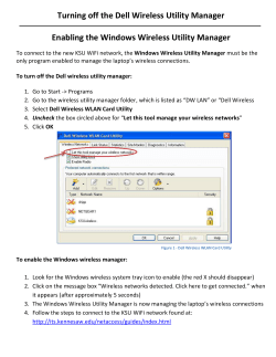
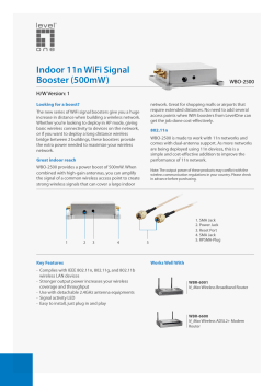


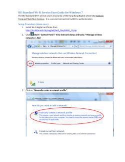


© Copyright 2026