
The behaviour of the secondary metallurgy slag into the EAF.
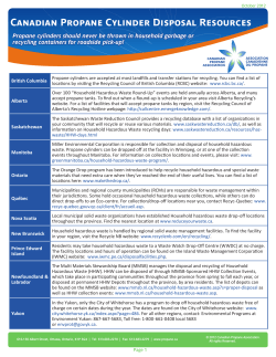
The behaviour of the secondary metallurgy slag into the EAF.
How to create a good foamy slag with the appropriate basicity
using a mix of lime and recycled ladle slag as EAF slag former
Marta Guzzon, Carlo Mapelli
Dipartimento di Meccanica
Sezione Materiali per Applicazioni Meccaniche
Politecnico di Milano, Milano (Italy)
Veena Sahajwalla, N. Saha-Chaudhury
Sustainable Materials Processing Research,
School of Materials Sciences and Engineering
University of New South Wales
Sydney (Australia)
Francesco Memoli
Tenova Metal Making (Techint Group)
Via Monte Rosa, 93 – 20149 Milano (Italy)
[email protected]
Michele Pustorino
Tenova Melt Shops (Techint Group)
Via Monte Rosa, 93 – 20149 Milano (Italy)
SUMMARY
Several steel plants, in Italy and in the rest of Europe, recycle with different
methods and techniques the slag proceeding from the secondary metallurgy
as slag former for their Electric Arc Furnaces.
In this paper the excellent results of this non-standard practice are analysed
and related to the characteristics of the EAF-slag resulting from this recycling.
An interesting effect has been found on the characteristics of foaming
velocity, slag basicity and slag density.
Slag foaming studies were conducted in the laboratories of UNSW (Sydney,
Australia) using the high temperature visualization facility. The studies have
established the differences in the slag foaming phenomenon between the
electric arc furnace slag formed with usual components (lime, dololime, etc.)
and the slag formed with the non-standard mix (lime and recycled ladle slag).
Using a model of isothermal solubility, developed by Politecnico di Milano
University (Italy), the other EAF slag properties, in particular the density and
the basicity, are correlated to the saturation of silicates, aluminates and other
complex components of the secondary metallurgy slag into the EAF slag.
The results of these studies confirm that this particular type of ladle slag
recycling is viable, as it does not affect the EAF foaming properties, and in
some cases it is even more favourable than the standard practice.
KEY WORDS
EAF Slag, Ladle Slag, Recycling, Powder Injection, Foamy Slag
INTRODUCTION
The Environment is becoming more and more a key issue for the Steel
Industry. In particular areas where the increasing variable cost of production
and the cost of men work are reducing the profit on the final product, the
additional cost of residues dumping can reduce to zero the result of the steel
plant. In Italy the production of steel using Electric Arc Furnaces generates
more than two million tons of slag and various types of other residues per
year. The recycling of these by-products permits to achieve two important
goals: minimizing the exploitation of natural resources and reducing the
amount of waste material. In Italy, the first Industrial Plant for recycling
electric arc furnace and ladle furnace by-products has operating since
January 2001 at Ferriere Nord works in Osoppo (Italy) - on industrial scale
since January 2003. The Plant convert ladle slag – also called “white slag” –
and spent refractory into a final powder mix that can be injected in the
Electric Arc Furnace through specially designed injectors. The industrial
application has shown the sustainability of this recycling procedure, cost and
process-wise. Important benefits, moreover the reduced cost for slag
disposal, is coming from the reduced amount of lime to add to the Electric
Arc Furnace, about 35% less. The application of this recycling process
provides major advantages, such as the lower amount of lime required for
the formation of the EAF slag. However this is not the only existing benefit.
The foaming properties of the slag are thus increased, and so the electrical
energy efficiency is increased, as the arc can be better covered during flat
bath operation. Nevertheless, the increase of tenor of MgO in the EAF slag
is in favour of a lower consumption of the EAF refractory bricks, an additional
benefit to be considered. [ref: 1].
SLAG FOAMING
Some important benefits can be obtained in the EAF through the foaming
slag practice. Slag is not foamed only to protect the refractory bricks from the
arc and to lowered the electrodes consumption but also to improve the heat
transfer from the arc to the metallic bath, and to decrease melting time. The
reactions that generate gas bubbles are required for the process of slag
foaming. The slag must have some physical and chemical characteristics to
sustain the gas bubbles.
Physical Characteristics for a Good Foaming Slag
The formation and stability of foams are influenced by surface tension and
viscosity. The steady state foam height increases with decreasing surface
tension. This can be attributed to the fact that the internal energy of the foam
resulting in a higher foam thickness. The viscosity increases the liquid drins
out of the foam at a slower rate. The liquid film separating the bubbles is
more stable and increase the life time of bubbles in the foam as well as the
foam thickness.Foaming characteristics improved with decreasing surface
tension and increasing viscosity of slag. However the presence of second
phase particles improves the foaming behavior. The best foaming properties
have a consistency between “creamy” and “fluffy”. This means that the best
slag is not completely liquid but is saturated with respect to CaO and MgO.
The second phase particles serve as gas nucleation sites, which lead to a
high amount of favourable small gas bubbles and promote a better stability.
According to this theory, the ISD
MW+liquid
diagram shows that the “optimum”
foaming slag is saturated with
C2S
C2S and Magnesia-wustite solid
MW
liquid
solution. In this diagram the better
foaming slag is between the
continue lines and dotted line. In
liquid
C2S
this region of diagram the slag is
liquid
not fully liquid and is not crusty
and there are the second phase
Figure 1: ISD at 1600°C showing initial slag (•)
particles suspended in the slag.
and three targets ( ) for good foaming slags (a)
In fact thisregion corresponds to
at 40 %FeO and (b) at 30 %FeO relative to the
the saturation of CaO and MgO.
curve for B3=2.0 and (c) with 30%FeO for
This signifies that the presence
B3=1.5. [ref: 2 ]
of C2S (2CaO.SiO2) suspended in the slag offers an advantage to foaming.
Chemical Characteristics for a Good Foaming Slag
The formation and the stability of foam is influenced by the chemical
composition of the slag. Since usually the refractory slagline in the EAF is
basic, in the slag composition is required the CaO and MgO saturation.
However these oxide saturations are needed for a good foaming behavior.
The foaming slag stability is favoured by the presence of silica. Silica lowers
the surface tension and promotes the formation of small bubbles of CO.On
the other hand, sulphur suppresses the slag foaming. Sulphur tends to
increase the size of CO bubbles and make worse the stability. [ref:3, 4 and 5]
Gas generation
In the foam the gas bubbles are constituted from CO and in smaller amount
from CO2. In the EAF the CO is formed from these reactions:
2C (in the bath or injected) + O2 = CO
(1) ;
FeO + C = Fe + CO
(2)
In these experiments, only the reaction (2) can occur because there isn’t
injection of oxygen. The presence of high percentage of FeO in the slag
promotes the reaction with the carbon and influences the foaming behavior
because is the only source of oxygen for the CO bubbles.
Influence of Recycling Material
From a chemical point of view, the injection of recycling material increases
the amount of the already present di-calcium silicate of EAF slag favouring
the saturation respect to C2S. The injection of recycling material influences
also the physical characteristics of foam. In fact the dicalcium silicate is
normally present at EAF slag temperature as “second phase particles”. The
addition of other particles coming from the recycled mix has three
consequences: a mass effect (lowering FeO, and increasing slag width), the
increase of MgO (present in the mix) and the increase of the CO nucleation
sites, which leads to a high amount of favourable small gas bubbles in the
foamy slag.
In order to understand the behaviour of EAF slag with recycling materials
some experiments have been conducted in the laboratories of UNSW using
slag samples with recycling materials and without recycling materials.
EXPERIMENTS
In this project, the foaming behaviour of slag with recycling material is
investigated in a horizontal tube furnace. The sessile drop technique is used
for slag foaming experiments. The purpose is to compare the effect of the
recycled ladle slag materials during slag-carbon interaction.
Samples Slag Description
The slag samples are taken from a steelwork that recycles the ladle slag in
the EAF. The samples for the experiments are selected from the samples as
representative for the typical heats both with and without recycling material.
Two types of EAF slag samples are used in the experiments:
• The first type of slag samples are with recycled ladle slag
•
Heat
Ton.
Lime (kg)
A
B
C
D
E
131
121
148
130
128
2885
2887
2972
2895
2889
Ladle Slag
(kg)
2460
2395
2404
2414
2407
Carbon (kg)
521
160
149
198
194
Oxygen
(Nm3)
3561
4370
4912
3361
3061
temperature
(°C)
1570
1575
1580
1570
1585
Table I: characteristics of heat with recycling material
The second type are without recycled ladle slag
Heat
Ton.
Lime (kg)
F
G
H
I
L
129
128
127
130
134
3432
3538
3540
2982
3000
Ladle Slag
(kg)
0
0
0
0
0
Carbon (kg)
322
231
234
254
584
Oxygen
(Nm3)
3207
3316
3055
3196
3457
temperature
(°C)
1575
1575
1580
1610
1580
Table II: characteristics of heat without recycling material
In the following table are reported the chemical analysis of every slag
sample:
The experiment sample consists of a coal substrate and a slag sample. The
slag sample is powderized and placed over the substrate sample.
Heat
FeO
Fetot
CaO
SiO2
MgO Al2O3 MnO
A
B
43,14
33,97
33,44
26,34
23,79
31,11
14,92
16,47
2,14
2,27
6,25
6,19
5,34
5,37
0,11
0,08
S
P2O5 Cr2O3 TiO2
0,60
0,82
0,52
0,78
0,36
0,38
97,16
97,45
C
D
E
37,16
36,09
32,25
28,80
27,98
25,00
28,69
28,40
30,89
15,34
16,66
17,39
3,24
2,70
2,44
7,23
6,71
6,89
3,74
5,02
5,93
0,10
0,08
0,08
0,72
0,72
0,65
0,75
0,59
0,56
0,38
0,38
0,41
97,35
97,38
97,50
F
G
24,40
24,39
18,92
18,90
33,13
34,32
20,36
18,90
2,79
3,17
8,49
8,80
6,41
6,01
0,06
0,04
0,96
1,10
0,66
0,54
0,49
0,48
97,74
97,74
H
I
L
27,34
27,84
35,79
21,19
21,58
27,75
32,87
28,55
23,80
18,01
19,40
18,24
2,56
3,11
2,32
8,40
10,27
9,60
6,14
6,29
5,90
0,05
0,04
0,06
1,20
0,92
0,53
0,61
0,65
0,63
0,47
0,56
0,51
97,65
97,64
97,39
Table III: chemical analysis of slag samples
Total
Preparation of Substrate
The substrates used in the slag foaming experiments, were prepared from
the metallurgical coke. Each sample was ground to a fine powder with
particle size <10 m, using a Rocklabs rotation grinder fed with compressed
air. The grinding container and ball were cleaned with ethanol before every
use to prevent contamination of samples. 1 gram of coke powder was then
placed in a die cylinder and uni-axially pressed at 7 tonnes for 1 min [using
the Enerpac 10 tonnes press]. The compacted, circular substrate of diameter
15 mm and thickness 3-4 mm was then
Metallurgical Coke
removed from the die and placed on the
Ash
18,30%
alumina stage. No binder was used in
Moisture
1,30%
compacting
the
materials
to
avoid
Volatile Matter
3%
contamination.
Fixed Carbon
78,70%
The composition of the metallurgical coke
Sulphur
0,32%
used in the experiments is reported in table IV:
Tab.IV: Analysis of metallurgical coke
Preparation of Slag Sample
The EAF slag sample was ground in a fine powder using a Rocklabs rotation
grinder. A quantity of 0,1 g of powder slag is placed over the compacted
coke substrate.
The foaming experiments were conducted in a laboratory scale horizontal
tube furnace using the sessile drop method. [ref: 5, 6]
At the start of the experiment, the sample is placed on an alumina holder, in
the cold zone of the furnace to eliminate any premature reaction. When the
required experimental temperature (1550°C) and inert atmospheric condition
are attained, the sample and holder are advanced to the hot zone, in
preparation for the slag-carbon interaction study. The furnace was purged
with argon gas throughout the duration of the experiment. Argon flow rate
was controlled by a mass flow meter and the gas flow rate was 1L/min. The
experimental temperature is controlled using the digital temperature indicator
on the furnace. A high quality, high resolution CCD camera fitted with IRIS
lens is used to capture live, the “in-situ” foaming phenomena in the furnace.
A DVD-TV system is used to record the entire foaming process, and the
recorded images are then transferred onto a computer. Slag foaming is
characterized by direct continuous measurement of foaming height as a
function of time. The volume of the molten slag droplet will be measured
using the image analysis software based on digital integration and used in
computer programming. In this way it is possible to calculate the volume
ratio as:
Where V0 is the starting volume value of the bubble and Vt the actual volume
value of the bubble.
RESULTS
The experimental results have confirmed the general principles of foaming
practice: the graphs 1, 3 and 4 confirm that the %FeO influences, during the
experiments, the reaction with carbon. Higher %FeO increases the foam
volume because FeO is the only source of oxygen for the formation of CO
bubbles, in this particular type of laboratory experience.
Graph 1 shows the
experiments with slag
samples without recycling
material. The sample L
has the better behavior
with high volume ratio
and better foam stability.
The chemical analysis,
reported in table 1, show
that the slag L is the one
that has higher %FeO.
This is in related to the
Graph 1: Volume ratio for slag samples without recycling
fact that higher FeO in
material (L, F and G)
the slag favours the
reaction with carbon.For
this reason comparisons
have to be done at same
%FeO.
Graph 2 shows the
comparison between the
slag L without recycling
material and the slag D
with recycling material.
Both samples have the
same value of FeO.The
slag D has a higher
volume ratio and better
stability, although this one
Graph 2: volume ratio for slag samples L without
recycling material and D with recycling material at
has a little lower SiO2
same FeO%
and higher S. In fact from
literature higher SiO2 and
lower S are favourable
factors for the foaming
slag stability.
Graph 3 shows the
comparison between the
slag L without recycling
material, the slag D with
recycling material at the
same %FeO and the slag
A with recycling material
with higher %FeO. The
Graph 3: volume ratio for the slag samples L, D and A
slag A has a highest
volume ratio, in according with the high FeO, but a lower stability. This
slaghas a lower value of SiO2 and higher S, factors that make worse the
foaming stability.
Graph 4 shows the comparison between the slag L without recycling material,
the slag D with recycling material at the same %FeO and the slag E with
recycling material
with little lower %FeO.
This slag presents the
best foaming behavior.
The volume ratio is lower
than slag D according to
the lower %FeO, but
higher than slag L without
recycling material. The
foaming stability is the
best one and this in
agreement
with
the
chemical analysis: high
SiO2 and low S.
Graph 5: volume ratio for the slag samples L, D and E
CONCLUSION
The experimental results are confirmed the general principles of foaming
practice: Graphs 1, 3, 4 and 5 show that the presence of recycling material
improves the foaming behavior, in particular:
- there is a higher volume ratio with recycling material (refer to
pictures below);
- there is a better foaming slag with recycling material;
A plausible explanation of these phenomena is that the C2S present in the
recycling material, as the second phase particles, can be nucleation sites for
small CO bubbles increasing the number of bubbles and the final foam
volume. Moreover the effective viscosity increases, with consequent
increase of bubble stability.
The following pictures show the foaming behavior for the slag L without
recycling material. The pictures are taken at 0, 30, 60, 90, 120, 210 sec.
Figure5: pictures at 0, 30, 60,90, 210 sec for the sample L without recycling material. the
VD 2 is
42% bigger than
VD1
The following pictures show the foaming behaviour for the slag E with
recycling material at the same time.
Figure 6: pictures at 0, 30, 90, 210 sec for the sample E with recycling materialThe
160% bigger than
VD1
VD 2 is
As shown in the graph 5, the foam with recycling material is much more
stable than the case without injection recycling material.
REFERENCES
1. F. Memoli, M. Guzzon, C. Mapelli: “Recycling of Ladle Slag in the EAF: a
Way to Improve Environmental Conditions and reduce Variable Cost”
presented at ATS 2006, Paris.
2. Oltmann, H.; Pretorius, E.: “Improvements in EAF operation by the use
of refining simulation tools and mass-balance programs for foaming
slag”, ABM XXXIV Steelmaking Seminar, May 12-19, 2003
3. Turkdogan E. T., “Physico chemical properties of molten slags and
glasses”. The Meals Society, London, 1983, pp. 224
4. V. Sahajwalla, M. Rahman, L. Hong, N. Saha-Chaudhury, D. Spencer:
“Influence of Carbonaceous Materials on Slag Foaming Behavior during
EAF Steelmaking” presented at AISTech 2005.
5. V. Sahajwalla, R. Khanna, M. Rahman, Z. Huang, N. Saha-Chaudhury,
D. Knights, P.O’Kane: “Recycling of Waste Plastics for slag Foaming in
EAF Steelmaking” presented at AISTech 2006
6. M. Rahaman, V. Sahajwalla, R. Khanna, N. Saha-Chaudhury, D. Knights,
P. O’Kane: “Fundumental Understanding of Carbonaceous Materials’
Influence on Slag Foaming Behaviour during EAF steelmaking”
presented at AISTech 2006.
7. E. V. Danilov: “Modern Technology for Recycling Steelmaking Slags”,
Metallurgist, Volume 47, Issue 5-6, May - June 2003, pp. 232 - 234
8. Shen H., Forssberg E., “An Overview of Recovery of Metals from Slags”,
Waste Management, Volume 23, No.10, 2003, pp. 933-949
9. Sano N., Lu W.K., Riboud P.V., Maeda M., “Advanced Physical
Chemistry for Process Metallurgy”, Academic Press, 1997
10. Geiseler J., “Use of Steelworks Slag in Europe”, Waste Management,
Volume 16, 1996, Issues 1-3, pp. 59-63
11. Kubaschewsky, O.; Alcock, C.B.: “Metallurgical Thermochemistry”, 5th
ed., Pergamon Press, Oxford, 65, 1979
12. Richardson F.D., “Physical chemistry of melt in metallurgy, vol. 2”.
Academic Press, London (UK), 1974
13. Pretorius, E; Carlisle, R.C.: “Foamy Slag Fundamentals and their
Practical Application to Electric Furnace Steelmaking”, Iron &
Steelmaking, 1999, No.10, pp. 79-88
14. D. Lotun, L. Pilon, “Physical Modeling of Slag Foaming for Various
Operating Conditions and Slag Compositions”, ISIJ International, Vol.45
(2005), No.6, pp. 835-840.
15. A. Kapilashrami: “Interfacial Phenomena in Two-Phase System:
Emulsions and Slag Foaming” Doctoral Thesis 2004, KTH.
16. J.J.L. Lee “Waste Plastics in Electric Arc Furnace Steelmaking.
Combustion and Slag Foaming.” Thesis, 2006 UNSW.


© Copyright 2026