
Title: How to roll out PCB Editor using SITE and HOME
Title:
How to roll out PCB Editor using SITE and
HOME
Product:
OrCAD / Allegro PCB Editor
Summary:
There are different ways to administrate
PCB Editor. This Note shows how the
different mechanisms work together.
We also add a chapter about
administration of capture.ini to manage
path and other global data.
Author/Date: Beate Wilke / 17.04.2013
This Application Note replaces the 2 Application Notes:
• FlowCAD_AN_PCB_site - How to roll out PCB Editor using Site
• FlowCAD_AN_PCB_environment - PCB Editor Environment
Application Note
PCB Site
Page 1 von 20
Table of Contents
1
2
3
4
5
6
7
8
Introduction .................................................................................................................... 3
1.1
Global env definitions .............................................................................................. 3
1.2
SITE definition ......................................................................................................... 3
1.3
HOME definition ...................................................................................................... 4
1.4
Cadence Variables Summary .................................................................................. 4
Defining a Variable ......................................................................................................... 4
2.1
Example: HOME Variable........................................................................................ 4
Read Order .................................................................................................................... 6
Global Content ............................................................................................................... 6
4.1
File_management > Output_dir ............................................................................... 7
4.2
File_management > Versioning ............................................................................... 7
4.3
Manufacture > NC_legend ...................................................................................... 7
4.4
Paths > Config ........................................................................................................ 8
4.5
Paths > Editor ......................................................................................................... 8
4.6
Paths > Library ........................................................................................................ 8
4.7
Path Syntax ............................................................................................................. 9
4.8
Funckey .................................................................................................................10
Structures ......................................................................................................................12
5.1
Site structure ..........................................................................................................12
5.2
Skill and Allegro.ilinit ..............................................................................................13
5.3
PCBENV ................................................................................................................13
Rollout ...........................................................................................................................14
6.1
Board Template......................................................................................................14
6.2
Symbol Template ...................................................................................................15
6.3
Parameter Files ......................................................................................................16
6.4
Technology Files ....................................................................................................16
6.5
Views .....................................................................................................................16
6.6
Scripts ....................................................................................................................17
6.7
Drill Legends ..........................................................................................................17
6.8
Material ..................................................................................................................17
6.9
DFA ........................................................................................................................17
CDSROOT - Working with different Software Versions..................................................17
7.1
Cadence Switch Release .......................................................................................17
7.2
Batch Files .............................................................................................................18
Capture.ini .....................................................................................................................18
8.1
CIS Admin Tool ......................................................................................................18
Application Note
PCB Site
Page 2 von 20
1 Introduction
PCB Editor and DE HDL can use up to 3 different sources for path and environment settings.
This are:
• Global env definitions - default settings after installation, do not change it
• SITE definition
- company/team settings
• HOME definition
- personal settings
Global env and HOME definitions are always used. Site can be used. It is designed to
manage environment for larger design teams or whole companies.
OrCAD Capture and DE CIS have their own environment definition. Please look at chapter 8
for more information.
In this document the main focus are definitions for PCB Editor.
1.1 Global env definitions
The global env file is stored in Cadence installation directory under share\pcb\text. If you
don’t know the exact location of the installation, look at system or user variable CDSROOT.
In chapter 2 we explain how to get the variables and how to change or add a variable.
Important: Never change the global env File and all files which are stored in
%CDSROOT/share/pcb.
1.2 SITE definition
A Site manages all path and environment settings which are unique for all users.
After the installation PCB Editor and DE HDL use an empty default site structure. It’s located
in %CDSROOT/share/local/pcb for PCB Editor and %CDSROOT/share/local/cdssetup for
DE HDL. Because the software installation often is on local system this structure can’t be
used because all users should use the same Site definition.
If you work with 3 or more persons with PCB Editor and DE HDL it’s better to define your
own Site. This Site should be located in a central folder. A good idea is to create a shared
folder on a server which contains Site, library and other global files which are used by all
users. It’s perfect if you could map this shared folder under the same network drive character
for all users.
CAD admin or IT has to do changes only in SITE definition and all users automatically get all
changes.
Depending on the used Tools you can define:
• CDS_SITE – Site definition for PCB Editor and DE HDL
• Allegro_SITE - Site definition only for PCB Editor
Application Note
PCB Site
Page 3 von 20
1.3 HOME definition
HOME stores all user specific path and environment information. If you work with less than 3
persons with PCB Editor and DE HDL you don’t need SITE definition. You can store all
information in HOME definition.
1.4 Cadence Variables Summary
PCB Editor and DE HDL use these main environment variables:
•
•
•
•
•
CDSROOT
CDS_LIC_FILE
HOME
CDS_SITE
Allegro_SITE
- Path to installation directory
- Port and Name of license manager
- Path to user environment
- Path to site environment for PCB Editor and DE HDL
- Path to site environment only for PCB
2 Defining a Variable
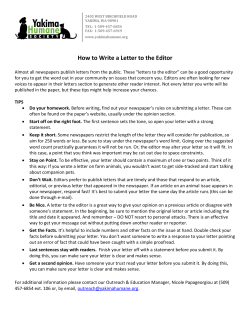
2.1 Example: HOME Variable
HOME is a user variable that defines
the location for your PCB Editor and
DE HDL environment settings. Since
16.6 capture.ini is also stored in
HOME folder. Every user needs its
own HOME folder.
To change the HOME variable, go to
Start -> Settings -> Control Panel > System -> Advanced ->
Environment Variables.
Application Note
PCB Site
Page 4 von 20
Because Home is a user variable every user needs his own variable. If only one users works
on the system you can also define it as system variable.
If you want to change the variable select it and click on Edit.
You can change the value to all existing folder where the user has full privileges.
Use the same steps to define CDS_SITE or Allegro_Site if necessary.
If you work with 2 different versions for example 15.7 and 16.5 it would be good to have two
different HOME folders. One for 15.7 and one for16.5 with different path definitions for library
because the binary code of 15.7 and 16.5 board files and symbols is different. The same is
for Site definitions. We recommend saving current SITE and HOME before release change to
have always a defined backup.
Application Note
PCB Site
Page 5 von 20
3 Read Order
Allegro PCB Editor searches for setting in the following order:
$cdsroot/share/pcb/text
(System level)
$CDS_SITE/
(Site level)
$HOME/pcbenv/
(User level)
Settings from HOME level have the highest priority, Site level middle priority and
system level lowest priority.
4 Global Content
All definitions in this chapter can be done in local user env file or global site.env. It depends,
if you want to set them for all users or if a single user works in a different way. Good
examples are Funckeys. They map a keyboard key with a function. You will have global
settings, unique for all users and every user will create its own Funckeys. He will use the
summary of all Funckey definitions. If the same key is mapped to different functions in user
env and site.env the user definition will win. Remember Read Order in chapter 3.
You can use Setup > User Preferences in PCB Editor to set the definitions you want and test
them. They are stored in your %HOME/pcbenv/env file. Later you can move the definitions
you want as unique to site.env in Site definition.
The env file contains all path and environment definitions which are different from the default
system settings. You can also change the env file by open it with a text editor, it’s written in
ASCII. Attached to this Application Note is a site definition with some example file. If you
want you can also get a Site with an example component library for PCB Editor Capture and
DE CIS. Please contact FlowCAD Support.
Here is an overview of the most used path and environment settings. We used the Setup >
User Preferences structure to list them.
2 important path settings are padpath and psmpath. If you work with your own component
library you have to set them first.
Application Note
PCB Site
Page 6 von 20
4.1 File_management > Output_dir
Ads_sdart
Ads_sdplot
Ads_sdreport
The subdirectory to which artwork files should be written
The subdirectory to which plot files should be written
The subdirectory to which report files should be written
These sub directories are automatically created in the project folder where the BRD file is
stored.
4.2 File_management > Versioning
ads_autosaverevs
ads_boardrevs
ads_logrevs
ads_textrevs
ext_artwork
ext_drill
Enables file versioning for AUTOSAVE database files. Value <n> =
number of versions you want maintained. Default is no versioning.
Enables file versioning for allegro layouts (.brd) and symbol (.*sm)
files. Value <n> = number of versions you want maintained. Default is
1 version.
Enables file versioning for Allegro log files. Value <n> = number of
versions you want maintained.
Enables file versioning of allegro files which are not .brd .*sm or .log
Value <n> = number of versions you want maintained.
File extension used for artwork (film) files. Default is .art.
Recommendation is to set this at the CDS_SITE level. Use caution
before changing the extension to ensure all your post-processing tools
can handle the new extension.
File extension used for ncdrill files. Default is .drl. Recommendation is
to set this at the CDS_SITE level. Use caution before changing the
extension to ensure all your post-processing tools can handle the new
extension.
4.3 Manufacture > NC_legend
nclegend_file
Application Note
PCB Site
Override the default filename convention for NC Drill Legend. By
default, NC Drill Legend uses a name of default-<units> where units
are the current board units. The override name should contain only the
filename not a PATH component.
Page 7 von 20
4.4 Paths > Config
Clippath
Dfaauditpath
Dfacnspath
Ipc2581attrpath
Ldfpath
Lstpath
Materialpath
Search path for sub-drawing files (.clp).
Search path for DFA Audit (.arl .rle).
Search path for dfa constraints spreadsheet files (dfa).
Search path for IPC2581 property configuration file(.atr).
Search path for Library definition file (.ldf).
Search path to locate list files (.lst).
Search path to locate materials.dat (Allegro) or mcmmat.dat
(APD) (.dat).
Search path for NC Drill files (.txt).
Search path for scripts.
Search path for extracta command files (.txt).
Search path for visibility schema files (.color).
Search path for Allegro templates (.brd .dra).
Ncdpath
Scriptpath
Textpath
Viewpath
wizard_template_path
4.5 Paths > Editor
Menupath
Search paths for menu files.
4.6 Paths > Library
Modulepath
Padpath
Parampath
Psmpath
Steppath
Techpath
Application Note
PCB Site
Search path for design reuse modules (.mdd).
Search path for library padstacks (.pad).
Search path for parameter files (.prm). These allow reuse of physical
design data option settings like text, visibility and grid settings.
Search path for library symbols (.psm .osm .bsm .ssm .fsm).
Search path for STEP files (.stp, .step)
Search path for technology files (.tech).
Page 8 von 20
4.7 Path Syntax
When you first open padpath after installation and enable Expand box you find these path
settings at the beginning.
.
symbols
..
../symbols
Application Note
PCB Site
Dot is for local folder. We recommend adding the dot at the beginning
of every path definition. PCB Editor “sees” all local file which make it
easier to test new configuration files or other new file.
Looks for the sub folder symbols and use it for search.
Looks one level above local folder
Looks for a sub folder one level above (parallel folder).
Page 9 von 20
4.8 Funckey
In the PCB Editor training you will learn how to define temporary Funckeys. To get a
permanent definition you have to define the funckeys in the env file. Here some examples for
Funckey definitions:
These funckeys switch layers on and off. It's similar to key functions of OrCAD Layout. They
use additional skill routines to run.
funckey 0 'settoggle lay all_layer all_layer_nil; $lay'
funckey 1 'settoggle lay lay_top lay_top_nil; $lay'
funckey 2 'settoggle lay lay_bot lay_bot_nil; $lay'
funckey 3 'settoggle lay lay_2 lay_2_nil; $lay'
funckey 4 'settoggle lay lay_3 lay_3_nil; $lay'
funckey 5 'settoggle lay lay_4 lay_4_nil; $lay'
funckey 6 'settoggle lay lay_5 lay_5_nil; $lay'
funckey 7 'settoggle lay lay_6 lay_6_nil; $lay'
funckey 8 'settoggle lay lay_7 lay_7_nil; $lay'
funckey 9 'settoggle lay lay_8 lay_8_nil; $lay'
funckey ~0 'settoggle lay lay_9 lay_9_nil; $lay'
funckey ~1 'settoggle lay lay_10 lay_10_nil; $lay'
funckey ~2 'settoggle lay lay_11 lay_11_nil; $lay'
funckey ~3 'settoggle lay lay_12 lay_12_nil; $lay'
funckey ~4 'settoggle lay lay_13 lay_13_nil; $lay'
funckey ~5 'settoggle lay lay_14 lay_14_nil; $lay'
funckey ~6 'settoggle lay lay_15 lay_15_nil; $lay'
funckey ~7 'settoggle lay solder_top solder_top_nil; $lay'
funckey ~8 'settoggle lay solder_bot solder_bot_nil; $lay'
funckey ~9 'settoggle lay paste_top paste_top_nil; $lay'
funckey ~A0 'settoggle lay paste_bot paste_bot_nil; $lay'
funckey ~A1 'settoggle lay silk_top silk_top_nil; $lay'
funckey ~A2 'settoggle lay silk_bot silk_bot_nil; $lay'
funckey ~A3 'settoggle lay assembly_top assembly_top_nil; $lay'
funckey ~A4 'settoggle lay assembly_bot assembly_bot_nil; $lay'
funckey ~A5 'settoggle lay drill drill_nil; $lay'
funckey ~A6 'settoggle lay test_top test_top_nil; $lay'
funckey ~A7 'settoggle lay test_bot test_bot_nil; $lay'
funckey ~A8 'settoggle lay dimension dimension_nil; $lay'
funckey ~A9 'settoggle lay drawing drawing_nil; $lay'
Funckeys for the standard functions of right mouse button
funckey Esc cancel
funckey u undo
funckey n next
funckey o oops
Application Note
PCB Site
Page 10 von 20
Funckeys for often used placement and routing funktions
funckey r "iangle 90"
funckey m "pop mirror"
funckey f "pop finish"
funckey w 'settoggle width 0.1 0.2 0.3 0.5 1 2; echo "Using width“ $width; options
acon_line_width $width'
funckey v 'settoggle grid_val 0.001 0.1 0.2 0.5 1 2; echo "Using grid" $grid_val; replay
$CDS_SITE\pcb\script\set_grid.scr'
Funckeys for managing the view
funckey a 'settoggle rats "rats all" "unrats all"; $rats; echo "Toggle Airlines"'
funckey q '"show element";echo "Query Element"'
funckey g 'grid toggle; redraw; echo "Toggle Grid"'
funckey d 'color -globvis on'
funckey c 'color -globvis off'
funckey z "zoom center"
funckey b "settoggle togfilm 'Film: TOP' 'Film: GND1' 'Film: I1' 'Film: POW1' 'Film: GND2'
'Film: I2' 'Film: POW2' 'Film: BOTTOM'; FORM vf_vis colorview_list $togfilm"
funckey h hilight
funckey j dehilight
funckey s 'shadow toggle'
funckey . drc update
funckey , "pick_to_grid -cursor;pick_to_grid -cursor"
Funckeys which are executed by mouse
button Swheel_up plus_global_transp
button Swheel_down minus_global_transp
button SCwheel_up plus_shape_transp
button SCwheel_down minus_shape_transp
button Cwheel_up plus_shadow
button Cwheel_down minus_shadow
Alias to move one grid unit with arrow keys, supported only in Placement Mode
alias SUp "move; ipick_to_gridunit 0 +1"
alias SDown "move; ipick_to_gridunit 0 -1"
alias SLeft "move; ipick_to_gridunit -1"
alias SRight "move; ipick_to_gridunit +1"
Every user can have its own set of Funckeys. Normally the System Administrator defines a
set of Funckeys for all users to get a unique handling of the tool.
We recommend don’t using i, x and y for funckeys. These characters are used to put in
coordinated and can confuse users.
Application Note
PCB Site
Page 11 von 20
5 Structures
In this chapter we describe the structure of the attached site example and additional files.
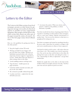
5.1 Site structure
The structure of attached example is:
You can modify the example, add or remove folders or create your own structure.
We will use the views folder as example, how it works.
In folder views you will find several views. A view contains the information which layers are
switched off or on. You can use them to quickly change the shows content on screen.
Site.env contains this row:
set viewpath = . $CDS_SITE/pcb/views
HOME env contains this row
set viewpath = $viewpath D:\Data\Home\166\pcbenv\views
Remember, HOME definition overwrites SITE definitions. That’s why you need $viewpath in
Home env. With this syntax PCB Editor reads local folder (.), $CDS_SITE/pcb/views and
D:\Data\Home\165\pcbenv\views to get the predefined views. Without $viewpath PCB Editor
will only look in Folder D:\Data\Home\165\pcbenv\views.
Application Note
PCB Site
Page 12 von 20
5.2 Skill and Allegro.ilinit
Skill is the PCB Editor internal programming language. You can define custom specific
menus and functions with Skill. The attached site includes 3 free skill routines and the
matching allegro.ilinit file.
At start up, Allegro PCB Editor looks for the allegro.ilinit file. This file contains the path of
SKILL files and loads the SKILL commands for use. The allegro.ilinit file is located in
$HOME/pcbenv folder and / or $CDS_SITE/pcb.
Example for an allegro.ilinit file:
load("./skill_data/cds2f.il")
load("./skill_data/layout.il")
load("./skill_data/display.il")
Skill can also be used in combination with funckey. Here are some examples of funckey
which start a skill routine to switch layers on or off.
funckey 0 'settoggle lay all_layer all_layer_nil; $lay'
funckey 1 'settoggle lay lay_top lay_top_nil; $lay'
5.3 PCBENV
PCBENV is a folder in the HOME definition and contains the user env file and additional user files.
These are the possible files:
Env
The User env file
allegro.ini
This file keeps track of the path where your working file is located. It keeps
track of the size and location of the main tool window. DO NOT EDIT THIS
FILE if you are having problems with PCB Editor. This file can be deleted as a
form of troubleshooting. It will be recreated automatically the next time you
start PCB Editor.
allegro.mru
This file records a list of the most recently used board files. DO NOT EDIT
THIS FILE!
allegro.geo
This file remembers where the forms last came up and places the same type
of form in the same location. DO NOT EDIT THIS FILE!
my_favorites
Favorites from Setup > User Preferences
myfavorites.txt
This file contains which class/subclass(es) to be displayed in the MyFavorites
folder of the Color Dialog form.
pad_designer.geo
This records the Pad Designer form location and size.
pad_designer.mru
This records a list of most recently used padstacks and paths.
Application Note
PCB Site
Page 13 von 20
6 Rollout
During rollout of PCB Editor it’s important to define structures and information which helps all
users to start quickly an efficient with PCB Editor. Many of the following configuration files
are explained in PCB Editor Training. Because PCB Editor is a complex system we always
recommend booking Cadence trainings.
6.1 Board Template
A Board template is a board file which has no netlist information. It includes all settings which
are uniform for all boards or a type of boards. These settings could be:
Setup > Design Parameter > Display
Setup > Design Parameter > Design
Setup > Design Parameter > Text
Application Note
PCB Site
Page 14 von 20
A template can also include dimensions, preplaced mechanical and format symbols you
need for documentation. If you have components which are always on the same position like
connectors you can place them as Package Symbol with dummy reference designator.
6.2 Symbol Template
A Symbol template is a symbol file (*.dra) which has no placed pins or any graphic
information. It includes all settings which are uniform for all symbols. These settings could be
Setup > Design Parameter > Display, Design and Text like in board file template.
A symbol template can also include preplaced labels.
You can switch between the different symbol type by using Setup > Design Parameter >
Design > Drawing Type.
Application Note
PCB Site
Page 15 von 20
6.3 Parameter Files
Parameter files contain all color settings and settings from Setup > Parameter menu.
6.4 Technology Files
Technology Files contain spacing, physical and electrical rule sets and layer stackup.
6.5 Views
A view contains the information which layers are switched off or on. You can use them to
quickly change the shows content on screen. It doesn’t contain color settings.
Application Note
PCB Site
Page 16 von 20
6.6 Scripts
Scripts contain repeating actions. You can record them with absolute coordinates or relative
coordinates (macro mode)
6.7 Drill Legends
An Ncdrill file defines context and view of drill legends.
6.8 Material
In Cross Section you can set all available materials from material file on conductor and
dielecticum layer to define the real stackup und use it to calculate impedances.
6.9 DFA
DFA stand for “Design For Assembly”. We use a spreadsheet to manage the different
minimum spaces between components to design boards with correct placement for
assembly.
7 CDSROOT - Working with different Software
Versions
CDSROOT is the system variable which defines the install-dir you use to start the tools.
During installation this variable is automatically set. If you only work with one software
version you don’t need to take care of it. But if you work with 2 or more software
versions it’s important to know which value is just set. You can modify CDSROOT
manually, with Cadence Switch Release or use Batch Files.
7.1 Cadence Switch Release
Cadence Switch Release sets CDSROOT and all necessary Path settings. You start it by
selecting Start -> Programs -> SPBxxx -> Cadence Switch Release. Use always Switch
Release of the highest software version.
Note: Cadence Switch Release does not change the HOME variable.
Application Note
PCB Site
Page 17 von 20
7.2 Batch Files
Batch Files are short script file which sets variables and starts programs. The Batch File
creates a local environment to start a tool. For example you work with 15.7 and have a test
installation for 16.6 it would be the best to set all variable to 15.7 and use Batch Files to start
16.6. In this environment you have no risk to open and save a 15.7 board file with 16.5
because you have total different settings.
Example:
echo off
set CDSROOT=D:\SPB_16.5
set HOME=E:\HOME\165
Path=
C:\WINDOWS\system32;
C:\WINDOWS;
C:\WINDOWS\System32\Wbem;
%CDSROOT%\tools\PSpice\Library;
%CDSROOT%\tools\Capture;
%CDSROOT%\tools\bin;
%CDSROOT%\tools\pcb\bin;
%CDSROOT%\tools\specctra\bin;
%CDSROOT%\tools\libutil\bin;
%CDSROOT%\tools\fet\bin;
%CDSROOT%\tools\dfII\bin;
%CDSROOT%\tools\PSpice
call allegro
Note: The path setting must be one row. It’s divided into different rows for a better overview.
With a Batch File you can set different HOME variables for different tools or versions. This
helps to manage different component libraries
8 Capture.ini
Capture.ini contains all setting for DE CIS / OrCAD Capture CIS. In 16.6 it’s located in
%HOME\cdssetup\OrCAD_Capture\16.6.0. In all earlier release it located in CDSROOT/tools
capture.
Like PCB Editor Capture CIS needs global settings like library paths and user settings like
colors. In default installation all settings are in one user capture.ini. This makes it difficult for
CAD administrators to change e.g. library path.
8.1 CIS Admin Tool
Application Note
PCB Site
Page 18 von 20
If your OrCAD Capture CIS designers work in a multi-user networked environment, you can
leverage CIS functionality for easier management of your group's part and footprint libraries
and files you can browse. Placing libraries and files in a designated location forces all
engineers to pull information from a central source. This not only promotes data integrity,
since all users are getting part information from a common source, but also eases the burden
of administrating libraries.
You can download the tool at:
http://www.cadence.com/products/orcad/pages/downloads.aspx#cis16
Unzip the file and start OrCADIni.exe.
Prepare a master capture.ini file with text editor. Define all global settings and delete all user
specific settings. Open this file in OrCAD Ini File Administrator window with File > Select
MasterIni File.
Use GUI to check or change master ini settings. Look all important setting and right side of
GUI. Then use File > Select local Ini to import user capture.ini. Check and modify local
settings. Save both capture.ini.
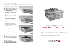
This is an example of master.ini. It has an additional section for lock settings.
Application Note
PCB Site
Page 19 von 20
Here are the same sections in user capture.ini.
You see that the section which are includes in master ini are empty in user ini.
For more information about CIS Admin Tool, look at OrCAD CIS User Guide, chapter
Additional CIS Utilities.
Application Note
PCB Site
Page 20 von 20


© Copyright 2026