
How to Properly Maintain Your UV Production System re tu
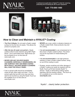
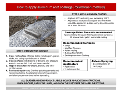
By Doug DeLong,
David Hagood and
Michael Kelly
Figure 1
Rotary atomizer
Key Goals: Eliminating Variability
in Your UV System
You have installed a UV coating
system. Now the question is, “how do
you intend to maintain your UV system
to insure your production throughput
is optimized?”
The goal of this article is to
provide you with an overview of the
industry’s best recommendations to
properly insure that your
UV coating system is
capable for the longterm. This feedback is
based on reviewing more
than 200 successful
UV applications in a
variety of markets and
customers, along with
consulting industry
experts in the UV
technology field. This
article also provides
best practices for effectively
maintaining your UV
production system.
Courtesy of Finishing Technology Solutions
QLighting
System:
• UV bulbs
• UV reflectors
• UV power supplies
• UV filters/materials
• UV blowers
QUV
Coating
Fluid Delivery System
Spray Equipment
Calibrating your spray equipment
(Figures 1 and 2) is an important
maintenance item and should be done
on a daily basis. First, you should run
a fluid flow check to determine if your
spray equipment is operating within
specification. The proper fluid flow rate
provides the right film build on your
parts. If the flow rate is too low, then
the film will be too low, thus creating
other problems such as poor corrosion
resistance, poor hiding power with
Figure 2
Overview of a UV System
HVLP guns spraying steel tube
Let’s start with a brief
review of the basic parts of a
UV coating system.
QFluid
Delivery System:
• Spray system (for this
example)
• Fluid monitoring system
• Coating heater
• Coating agitation
• Coating re-circulating
• Line purging and cleaning
18 RADTECH REPORT JANUARY/FEBRUARY/MARCH 2010
Courtesy of Finishing Technology Solutions
Feature
How to Properly Maintain
Your UV Production System
than required. Too much film build
simply wastes coating and costs dollars.
It can also affect the cure of the coating
which can cause other possible rejects.
Fluid Monitoring System
One simple way to know your fluid
delivery rate is to monitor or use closedloop flow rate control (Figure 4) using
a gear meter with a sensor and readout.
The open-loop flow monitoring system
(Figure 3) is designed to be installed
in the fluid stream that provides the
coating to the spray device. As the fluid
flows through the gear meter, a specific
amount passes through the teeth of
the gears. A sensor measures the rate
of gear movement and sends a signal
to an electronic unit that converts the
electrical pulses to a fluid flow rate. In
turn, the electrical unit displays the
flow rate on a readout unit.
For totally automatic control,
you can install a flow computer to
control a transducer that provides
an air signal to the fluid control
regulator. Once a flow rate is set, if the
monitoring system detects a different
flow rate than the set point, then it
sends a signal to the transducer to
automatically raise or lower the air
pilot pressure on the fluid regulator
to keep the flow rate within the set
point range. It is important to note that
some UV materials are not compatible
with a gear meter unit. The small fluid
passages between the teeth of the
gears create premature polymerization
of the coating. It is important to check
your coating for compatibility before
using this type of unit.
Figure 3
Other items to consider for a daily checklist:
• Check spray device for work
distance. It should always remain
consistent.
• Check spray pattern size to ensure
it is the same each day.
• If you are using electrostatic spray
equipment, perform an electrostatic
check to insure high-electrostatic
efficiency.
• Check to be sure the parts and work
holders are properly grounded.
• Perform an airflow check of
the spray booth to be sure it is
consistent from day to day.
• Monitor temperature and humidity
on a periodic basis throughout the
day and record.
All of these items will help ensure
a consistent running system. This will,
in turn, help provide a consistent finish
on the product day in and day out.
Open-loop flow monitoring
Coating Heater
It is critical to eliminate variability
Display
in the process, so heating the coating
to a specific temperature is very
Filter
Pressurized
Fluid Supply
Gear
Meter
Regulator
Spray Gun
important. There are a variety of
different methods to heat the coating
(See Figure 5).
Open Loop Flow Monitoring
• Hot water heating
This method typically involves
heating the coating lines with a blanket
of hot water (specifically dialed into
Figure 4
a specific temperature). This type of
heating uses special lines that jacket
Closed-loop flow monitoring
equipment. It uses a remote heating
Transducer
Flow
Computer
around the coating fluid lines and spray
system that heats the water and
circulates it through the special lines,
transferring the heat to the coating
Sensor
fluid lines.
Filter
Pressurized
Fluid Supply
Gear
Meter
Regulator
Spray Gun
• In-Line Coating Heater
This type of heater is thermostatically
controlled and uses an electric heating
Closed Loop Flow Control
element to heat a metal fluid housing
that typically has a spiral shape in which
the coating enters at the bottom of
the spiral and exits from the top of the
JANUARY/FEBRUARY/MARCH 2010 RADTECH REPORT 19
Feature
pigmented coatings and less protection
Courtesy of Finishing Technology Solutions
Examples of coating heating systems
spiral. As the coating passes through
the spiral, the heat is transferred to the
coating from the heating element. A
temperature readout indicates to the
operator the coating temperature as it
exits the heater.
In either case, the advantage of
heating most coatings is to reduce
the viscosity without having to use
solvents or monomers. A reduced
viscosity allows the coating applicator
to work more efficiently. The other
advantage of heat is to provide a
consistent temperature throughout
the course of a day and/or from
seasonal temperature changes. The
more consistent the coating viscosity,
the easier it is to control the fluid
delivery rate of the coating through
the spray device.
supply size (since most UV materials
are relatively high viscosity), a backgeared, air-motor driven agitator is
usually recommended. These are more
expensive than a simple air motor
agitator but are more consistent and
reliable. Figure 6 shows a back-geared
agitator system with an air-operated
elevator assembly for use with
55-gallon, open-top drums.
Coating Overspray Collection
and Reuse
100% solids UV coatings offer the
benefit of reclaiming any overspray,
filtering this material and reintroducing it back into the original
supply. This is a critical part of driving
toward maximum system efficiency
and offers a great return on investment
payback. There are many methods
Figure 6
Drum agitation systems
Coating Agitation
This should be a standard practice
for any UV coating installation.
Agitation of the coating eliminates
variability in your process and is
a best practice recommended by
UV-formulation suppliers.
The best way to agitate the coating
is to use an agitation blade, set for
an estimated 30-40 revolutions a
minute. Depending on the coating
20 RADTECH REPORT JANUARY/FEBRUARY/MARCH 2010
Coating agitator and coating drum heater.
Courtesy of Finishing Technology Solutions
Feature
Figure 5
is no need to open the pot to check the
coating level or, worse, to run out of
coating because of having to guess how
much coating is left.
Reclaim system
Courtesy of Finishing Technology Solutions
Maintaining UV Lights
Line Purging and Cleaning
When you have a coating system
with more than one coating (color or
clear), it is important to fully purge and
clean the UV coating lines. One simple
procedure is to mount a manifold block
as close to the actual spray guns and
run separate UV lines from each fluid
supply to the manifold block. You would
then have a separate fluid supply that
would contain a cleaning solvent, such
as alcohol or acetone.
This type of arrangement would
minimize color changeover and provide
a system that is fully maintainable
and simple. With a programmable
• Low-pressure UV fluorescent tubes
logic controller, a color change could
• LED-lamp technology
be achieved in 30 seconds or less.
• Medium-pressure UV arc lamps
Whether you use separate fluid supply
sources and lines to a manifold or
• Microwave-powered UV Lamps
simply use a single fluid supply to
• High-pressure short arc lamps
the spray devices, it is
important to flush the
coating from the lines and
through the fluid regulation
Pressure pot on scale
and spray equipment on a
regular basis. This keeps
the internal components
clean and working freely.
Figure 8
Best Practice Suggestion
Another good practice
(if you use pressure pots
for your fluid supply) is to
have your coating pressure
pots positioned on scales
(See Figure 8). When the
pressure pot is empty,
the scales are set to zero
pounds. Then, when the
coating is added, it will
provide a visual indicator
of the actual amount of
coating inside the pressure
pot. With this method, there
Courtesy of Finishing Technology Solutions
for achieving this. Most systems use
a reclaim baffle system that captures
a high percentage of the oversprayed
coating (See Figure 7).
It collects on the baffles and then
drains into a holding reservoir, where
it can be pumped through a bag filter
and back to the original fluid supply
for reuse. For multiple color systems,
one reclaim module is required for
each color. Many manufacturers use
individual reclaim modules for highvolume coatings and then have a single
module that may be used for many
colors that are small-volume users.
In this case, the coating may not be
reused, but by capturing it in the baffle
system, it keeps it from going into the
booth filters, thus extending the filter
life before changing them is required.
Question: When was the last time you
cleaned the reflector in your UV system?
Typically, it’s a simple question—
but it has a complex answer. Most
companies do not adequately maintain
their UV lighting systems (Figure 9). In
this section, we will provide a pictorial
overview to show the importance
of maintaining UV bulbs, reflectors,
power supplies, filters and blowers.
Greatly improved production uptime
will be achieved by the adequate and
thorough maintenance of a UV system.
There are many types of UV lamp
sources in use today:
JANUARY/FEBRUARY/MARCH 2010 RADTECH REPORT 21
Feature
Figure 7
Courtesy of DoctorUV.com
UV reflectors that have not been maintained
There are two primary types of UV
lamps installed in manufacturing today:
• Medium-pressure UV arc lamps
• Microwave-powered UV lamps
A clean bulb and reflector delivers
all the UV Spectrum in the ranges of
UVA, UVB, UVC and UVV. A dirty bulb
and reflector delivers very little of the
UV spectrum such as no UVB, no UVC
and reduced UVA and UVV (Figure 11).
Simple routine service intervals
and major maintenance intervals
should be followed.
• Measure the UV
lamp regularly.
• Record it in the
log book so you
know when the
bulb reflector is
bad or dirty.
• Clean the UV
lamp and reflector
regularly to
achieve consistent
UV output.
The above
three items are
recommended
monthly maintenance
Figure 10
UV lamps available today
Courtesy of DoctorUV.com
Figure 10 shows some examples of
UV lamps available today.
Figure 11
Clean UV spectrum versus dirty UV spectrum
Courtesy of DoctorUV.com
Feature
Figure 9
22 RADTECH REPORT JANUARY/FEBRUARY/MARCH 2010
Feature
Figure 12
Relative penetration where the UV goes in
UVC
UVB
UVA
UVV
Substrate Surface
UV Preventive Maintenance
Some typical questions regarding
UV preventive maintenance service:
• When should I do simple preventive
maintenance service?
• Is it when I measure the UV power
and it drops below the threshold of
my documented process window?
• How do I do measure this UV drop
with a calibrated UV radiometer
(Figure 13)?
UV Power Puck is a self-contained,
electro-optic instrument designed
to measure and display peak UV
irradiance and total UV energy density
used in the UV curing process.
Adhesion
Ink, coating, adhesive thickness
Ink, coating, adhesive thickness
items. Intervals any longer than a
month will raise the risk of having
production/quality issues.
UVA
Substrate Surface
A carefully designed optical sensing
system measures total UV energy
density on four different channels
simultaneously (Figure 12). These
four different channels represent four
different UV bandwidths of interest
for most curing applications—UVA
(320-390nm), UVB (280-320nm), UVC
(250-260nm) and UVV (395-445nm).
Establishing and Maintaining a UV
Process Window
By using the data provided by the
radiometer, true process control can
be achieved. At startup each day, the
operator exposes the radiometer to
the curing process, takes readings
and observes if the readings are
within the curing parameters for a
satisfactory cure for the particular
product to be run.
UVV
Adhesion
& Ti O2 cure
Courtesy of DoctorUV.com
UVC
UVB
Abrasion
Resistance Toughness
Process
The operator can make adjustments
by changing the length of exposure
time, cleaning reflectors or even
relamping in order to obtain the desired
UV levels, thereby assuring consistency
in the curing process. The radiometer
quantifies the UV curing system and
takes a great deal of guesswork out of
the overall curing process.
Another choice for measuring
UV is by using UV exposure tags.
The UV FastCheck1 is a tag that
provides UV-exposure dose monitoring
(including narrow web, difficult-toaccess, partially covered and threedimensional applications). FastCheck
tags provide good linearity color
change versus exposure dose; a large
dynamic range of exposure doses; and
Figure 13
Courtesy of EIT Inc.
Radiometer products
JANUARY/FEBRUARY/MARCH 2010 RADTECH REPORT 23
Process or cure window
Simple Preventive Maintenance
Service for Arc Lamps
• Start with a cool lamp system.
• Turn off the main power to the UV
lamp system.
a broad spectral. It also offers a good
comparison of multiple sources and is a
good quality control tool.
Process Window
• The process window is the range in
which a process will work to achieve
the desired results (adhesion,
hardness, flexibility, gloss, texture,
stain or scratch resistance, chemical
rub, cross-hatch, abrasion rub, color
ID and registration). See Figure 14.
• It is ideal if the process window is
forgiving and has a wide latitude. It
takes work and time.
• Invest before production and
confirm when things are working!
– Refer to the starting guidelines
from the formulator.
– Complete operator Training and
ISO/Procedure Documentation.
• Define your lower limits and
document the readings.
– Increase line speed/decrease
applied power until you
undercure, note readings and
cushion by 20%.
Figure 15
• Remove the lamp housing/reflector
assembly.
UV log book example
Keep a log book2 for each machine
and document the UV readings
(Figure 15). You will get a good feel for
the preventive maintenance schedule
needed for your unique operating
environment. Obviously, a dirty
environment will need more frequent
cleaning than a clean room application.
With cotton gloves, remove the bulb
being careful not to touch the bulb with
your bare hands. Clean with a Windextype glass cleaner and a lint-free cloth.
Alcohol (IPA) can also be used to clean
the UV bulbs and reflector. Important:
External deposits on the bulb are
difficult to remove and can eventually
Figure 16
Examples of clean versus dirty bulbs
• What are the upper limits?
• Monitor the readings by job,
hour, shift or day as required to
maintain quality.
• Establish the process window during
the design/development phase.
• Establish the process window when
things are working.
24 RADTECH REPORT JANUARY/FEBRUARY/MARCH 2010
Courtesy of DoctorUV.com
Feature
Dirty Versus Clean Arc Lamp Parts
Up to 70% of the UV light is bounced
off of the reflector, so a clean reflector is
critical to the maintaining the reliability
of the manufacturing system (Figures
16, 17 and 18).
Figure 14
This may be seen as a pitting of the
reflective surfaces, dark discoloration
on front face, top edges or at end of
reflectors. Replace entire reflector
assembly if any damage is observed.
Courtesy of DoctorUV.com
Reflector review
Simple Preventive Maintenance
Service for Microwave Lamps
Power Supply
There are no regular maintenance
procedures that apply to the power
supply except to check the cooling
fan(s) and replace filters, if so equipped.
Irradiator
There should be regular
maintenance at a minimum every 30
days of operation. (Dirty operating
environments may require more
frequent service.)
1. Remove the irradiator from its light
shield and place on a workbench
with the lamp cavity facing up.
2. Remove the radio frequency (RF)
screen assembly and inspect fine
tungsten mesh for any signs of
damage. Replace screen assembly if
there are any signs of damage (i.e.,
holes, tears, etc.).
3. Remove UV bulb and clean with
Windex-type glass cleaner and a
lint-free cloth. Alcohol (IPA) can
also be used to clean the UV bulbs
and reflector.
Important: External bulb deposits
are difficult to remove, and can
eventually contribute to a reduction
of UV energy at the irradiator
focal point.
4. Metal reflectors—Inspect the
reflector for signs of RF damage.
5. Reinstall UV bulb into lamp cavity,
being careful not to touch quartz
surface. If quartz bulb surface is
touched, clean with Windex-type
glass cleaner and a lint-free cloth.
6. Reinstall the RF screen over
irradiator lamp cavity and fasten
with screws provided. Hand tighten
all screws. Do not over tighten
these screws.
Note: Do not operate this
equipment with missing or damaged
hardware.
7. Reinstall UV irradiator into lightshield. (Be careful not to damage to
the RF screen mesh.)
Figure 18
Dirty versus clean reflectors
Courtesy of DoctorUV.com
contribute to a reduction of UV energy
at the focal point.
Metal reflectors—Inspect the
reflector for signs of deposits. Clean
the reflectors with Windex-type glass
cleaner or isopropyl alcohol (IPA) and
a lint-free cloth.
Note: The reflector should look like
a mirror. Can you look at it and shave
in the reflection? If you can’t see your
face in the reflector, it is time to
clean or replace that reflector.
Clean reflectors with Windex-type
glass cleaner or alcohol and a lintfree cloth. Retighten all reflector
screws. Normal irradiator operation
may cause these screws to loosen,
contributing to RF arcing or pitting
on the rear surface of the aluminum
reflector and wave-guides.
JANUARY/FEBRUARY/MARCH 2010 RADTECH REPORT 25
Feature
Figure 17
What is Major Service?
Major service includes replacing:
• Lamps (when power drops below
the set limit)
• Reflectors (every 2 to 3 bulb
changes)
• Magnetron on Microwave lamps
(as needed).
• Capacitors (if needed)
• Ballasts (if needed)
• Mercury contactor (if needed)
• Shutter Pneumatics (if needed)
These will generally restore
the lamp to like-new performance.
Remember to use common sense in
maintaining the UV production system.
Please set a company goal to:
• Measure the UV regularly
• Document the UV readings
• Routinely clean the bulb and
reflector for optimum performance
Measurement and Maintenance
Measurement and maintenance of
these systems is critical for optimizing
the UV coating system. In addition, it
is very important to use the correct
maintenance parts for all the systems
listed above. Production downtime and
product rework will be considerably
more costly to the operation than the
actual cost of maintenance parts.
One final area of consideration is
the use of written and pictorial work
instruction sheets for each of the
maintenance procedures. Outlined below
is a clip of an example work instruction
(Table 1).
Figure 19
Good lesson
Courtesy of EIT Inc.
Feature
8. Change lamp air supply filters on
a regular schedule to prevent the
buildup of foreign material on bulb,
reflector and magnetron assemblies.
UV Coating Material
It is critical to maintain the quality
control on all incoming UV materials.
UV materials are certified by the
supplier and have a Certificate of
Analysis (COA) that accompanies
each shipment.
Some Best Practices
• Inspect COA against previous
shipments to insure coating physical
characteristic consistency.
• Properly rotate all inventory—
insuring that older batches are
consumed first.
• Make sure the coating is being
agitated and held at a set
temperature.
• In some cases, it may be
appropriate to run a sample
drawdown on a specific substrate
and cure with UV lights.
• Then perform ASTM 3359D adhesion
test to insure correct adhesion.
Table 1
UV callibration work instructions
• Other specific ASTM-defined tests
can be completed at this time.
• Contact your coating supplier for a
list of specific ASTM tests that could
assist in the coating validation.
Conclusions
The key to maintaining a UV
production system is controlling
variability in the process. In this article,
three main areas were identified—fluid
delivery system, UV lighting system
and UV coating. Specific details and
recommendations/best practices were
explained with support documentation
and pictures. Z
Acknowledgements
The authors wish to thank Jim
Raymont at EIT for his contributions
to this article.
References
1. UV FastCheck is available from
UV Process Supply (www.uvps.com).
2. For a sample Excel Spreadsheet
example please visit
www.themiracleofUVlight.com
—Doug DeLong is president of DDU
Enterprises in Redondo Beach,
Calif. David Hagood is president
of Finishing Technology Solutions,
LLC, in Vermilion, Ohio. Michael
Kelly is CEO/president of Allied
PhotoChemical in Kimball, Mich.
Hagood and Kelly are members of
the RadTech Report Editorial Board
and serve as co-chairs of RadTech’s
Industrial Applications Focus Group.
26 RADTECH REPORT JANUARY/FEBRUARY/MARCH 2010


© Copyright 2026