
How to Manage Your Network with SPECTRUM Titlepage
Titlepage
How to Manage Your
Network with
SPECTRUM
SPECTRUM Enterprise Manager
Network Management
Notice
Aprisma Management Technologies, Inc. (Aprisma) reserves the right to make changes in
specifications and other information contained in this document without prior notice. The reader
should in all cases consult Aprisma to determine whether any such changes have been made.
The hardware, firmware, or software described in this manual is subject to change without notice.
IN NO EVENT SHALL APRISMA, ITS EMPLOYEES, OFFICERS, DIRECTORS, AGENTS, OR
AFFILIATES BE LIABLE FOR ANY INCIDENTAL, INDIRECT, SPECIAL, OR CONSEQUENTIAL
DAMAGES WHATSOEVER (INCLUDING BUT NOT LIMITED TO LOST PROFITS) ARISING OUT
OF OR RELATED TO THIS MANUAL OR THE INFORMATION CONTAINED IN IT, EVEN IF
APRISMA HAS BEEN ADVISED OF, KNOWN, OR SHOULD HAVE KNOWN, THE POSSIBILITY
OF SUCH DAMAGES.
Copyright © January 2001 by Aprisma Management Technologies, Inc. All rights reserved.
Printed in the United States of America.
Order Number: 9031909-02
Aprisma Management Technologies, Inc.
121 Technology Way
Durham NH 03824
SPECTRUM, the SPECTRUM IMT/VNM logo, DCM, IMT, and VNM are registered trademarks,
and SpectroGRAPH, SpectroSERVER, Inductive Modeling Technology, Device
Communications Manager, and Virtual Network Machine are trademarks of Aprisma or its
affiliates.
C++ is a trademark of American Telephone and Telegraph, Inc.
UNIX is a trademark of UNIX System Laboratories, Inc.
OSF/Motif and Motif are trademarks of the Open Software Foundation, Inc.
X Window System is a trademark of X Consortium, Inc.
Ethernet is a trademark of Xerox Corporation.
Virus Disclaimer
Aprisma makes no representations or warranties to the effect that the Licensed Software is virusfree.
Aprisma has tested its software with current virus checking technologies. However, because no
anti-virus system is 100% reliable, we strongly caution you to write protect and then verify that the
Licensed Software, prior to installing it, is virus-free with an anti-virus system in which you have
confidence.
How to Manage Your Network
Page 2
Restricted Rights Notice
(Applicable to licenses to the United States Government only.)
1. Use, duplication, or disclosure by the Government is subject to restrictions as set forth in
subparagraph (c) (1) (ii) of the Rights in Technical Data and Computer Software clause at
DFARS 252.227-7013.
Aprisma Management Technologies, Inc., 121 Technology Way,
Durham, New Hampshire 03824.
2. (a) This computer software is submitted with restricted rights. It may not be used, reproduced,
or disclosed by the Government except as provided in paragraph (b) of this Notice or as
otherwise expressly stated in the contract.
(b) This computer software may be:
(1) Used or copied for use in or with the computer or computers for which it was acquired,
including use at any Government installation to which such computer or computers may
be transferred;
(2) Used or copied for use in a backup computer if any computer for which it was acquired is
inoperative;
(3) Reproduced for archival or backup purposes;
(4) Modified, adapted, or combined with other computer software, provided that the modified,
combined, or adapted portions of the derivative software incorporating restricted
computer software are made subject to the same restricted rights;
(5) Disclosed to and reproduced for use by support service contractors in accordance with
subparagraphs (b) (1) through (4) of this clause, provided the Government makes such
disclosure or reproduction subject to these restricted rights; and
(6) Used or copied for use in or transferred to a replacement computer.
(c) Notwithstanding the foregoing, if this computer software is published copyrighted computer
software, it is licensed to the Government, without disclosure prohibitions, with the minimum
rights set forth in paragraph (b) of this clause.
(d) Any other rights or limitations regarding the use, duplication, or disclosure of this computer
software are to be expressly stated in, or incorporated in, the contract.
(e) This Notice shall be marked on any reproduction of this computer software, in whole or in part.
How to Manage Your Network
Page 3
Contents
Introduction
8
SPECTRUM Core and Network Management .............................................................9
Additional SPECTRUM Network Management ............................................................9
Optimizing Your Network Model
10
Before You Begin .......................................................................................................11
Optimizing Your Network Model .................................................................................12
Understanding Your Network Model .......................................................................12
Port Connection Representation .........................................................................15
Completing Your Network Model ............................................................................16
Generating an Inventory Report of Your Modeled Devices .................................17
Comparing the Inventory Report to Your Inventory List ......................................23
Modeling Devices Manually ................................................................................24
Resolving Port Connections ................................................................................25
The Device Topology View ..............................................................................25
Using the Device Topology View to Identify and Resolve Port Connections ...27
Rearranging Your Network Model ..........................................................................29
Management Capacity Options ..............................................................................33
Polling Intervals ...................................................................................................33
Setting Polling Intervals .......................................................................................35
Command Line Interface .................................................................................35
Model Information View ...................................................................................36
Setting Polling Intervals for Applications .............................................................36
Disabling Polling for Endpoints ...........................................................................37
Command Line Interface .................................................................................37
Model Information View ...................................................................................38
Customizing Your Network Model ..............................................................................39
Using the Annotation Toolbox ................................................................................40
Using the Change Background Option ...................................................................41
Changing Backgrounds ..........................................................................................41
Background Color ...............................................................................................42
Using Organizational Views ....................................................................................44
Maintaining Your Network Model ...............................................................................47
How to Manage Your Network
Page 4
Co n te nt s
Co n te nt s
Adding or Changing Devices on your Network .......................................................47
To remove a device model from your network model: ........................................47
To add a device model to your network model: ..................................................48
Scheduling Database Backups ...............................................................................48
To Backup Your Database From the Control Panel: ...........................................48
To Restore Your Database From the Control Panel: ..........................................49
To Schedule Regular Database Backups From the Control Panel: ....................49
Configuring for Fault Management
50
Setting Thresholds .....................................................................................................50
Alarm Thresholds ...................................................................................................50
Rollup Condition Thresholds and Significance Levels ............................................51
Configuring Traps .......................................................................................................53
Creating New Traps ................................................................................................54
Configuring Alarms .....................................................................................................60
Using SpectroWATCH ............................................................................................60
Configuring Redundancy ............................................................................................61
Redundant Paths ....................................................................................................61
Redundant SpectroSERVERs ................................................................................61
Fault Management
63
Fault Detection ...........................................................................................................66
What Does a Device Condition Color Indicate? .....................................................66
Contact Status Label Blue ...................................................................................67
Contact Status Label Green ................................................................................67
Contact Status Label Yellow ...............................................................................67
Contact Status Label Orange ..............................................................................67
Contact Status Label Red ...................................................................................68
Contact Status Label Gray ..................................................................................68
What Does a Rollup Condition Color Indicate? ......................................................68
How Is a Rollup Condition Detected? .....................................................................69
Audible Alarms .......................................................................................................71
Fault Isolation .............................................................................................................72
Enterprise Alarm Manager ......................................................................................72
Accessing the Enterprise Alarm Manager ...........................................................73
Using the Enterprise Alarm Manager ..................................................................75
Navigate In and Point and Click .............................................................................76
How to Manage Your Network
Page 5
Co n te nt s
Co n te nt s
Chassis Device View ..............................................................................................78
Accessing the Chassis Device View ...................................................................79
Device Topology View ............................................................................................80
Accessing the Device Topology View .................................................................80
Using the Device Topology View ........................................................................80
Performance View ..................................................................................................81
Accessing the Performance View .......................................................................82
Using the Performance View ...............................................................................82
What is in the Performance View? ..................................................................82
Pie Charts ........................................................................................................83
Troubleshooting with the Performance View ...................................................85
Beyond the Performance View ...............................................................................89
SPECTRUM Intelligence
90
Static Configuration of Device Models .......................................................................90
Dynamic Configuration of Device Models ..................................................................90
Model Status and Rollups ..........................................................................................92
Attributes Determining Condition and Rollup Condition .........................................94
Condition and Rollup Condition Sensitivity .............................................................97
Rollup Condition Flow .............................................................................................99
Example of Rollup Condition Propagation ............................................................101
Organization Models .............................................................................................106
Fault Isolation ...........................................................................................................106
Contact Status ......................................................................................................107
Models ..................................................................................................................109
Duplicate Addresses ................................................................................................118
Automatic Naming and Addressing in SPECTRUM .................................................120
Monitor Points ..........................................................................................................121
Monitor Point Statistics .........................................................................................122
Composite Monitor Point Statistics ...................................................................123
Discrete Monitor Point Statistics .......................................................................123
Monitor Point Calculations in SpectroWATCH ..................................................129
Detection of Firmware Problems ..............................................................................130
Device Threshold Events .........................................................................................130
Redundancy .............................................................................................................130
Alternate Path Repeater Management .....................................................................135
Device Lost and Found ............................................................................................136
How to Manage Your Network
Page 6
Co n te nt s
Co n te nt s
Device Type Verification ..........................................................................................136
Device Type Mismatch .........................................................................................137
In-Band Configuration of Device Alarms ..................................................................138
Interface Intelligence ................................................................................................138
Interface Alarms ...................................................................................................141
Interface Events ....................................................................................................142
Index
How to Manage Your Network
144
Page 7
Introduction
SPECTRUM is a powerful and flexible network management software
program that provides a network administrator with effective and reliable
network management tools. Reliable network management has become a
necessity to maintain a competitive edge in today’s market place.
SPECTRUM’s diversity of features and functionality can seem
intimidating to an administrator just beginning to use the product. Not
only does the SPECTRUM core* product provide a wide variety of features
and functionality, but an additional array of separately purchasable
Aprisma or third-party add-on components offers the means for further
customizing or extending SPECTRUM. Given these extensive management
capabilities, the need for a book describing the use of these network
management tools has become increasingly important.
This document is an attempt to address the need for a “how to” approach
in using SPECTRUM to effectively manage a network. The focus will be on
the management features included with the core product and how to use
them.
* Core product refers to those components included in the basic SPECTRUM
package.
How to Manage Your Network
Page 8
In tro d uc t i on
S P E CT R UM C o r e an d Ne t wo r k M an a ge m en t
SPECTRUM Core and Network Management
Using SPECTRUM to successfully manage your network involves reducing
network downtime, improving network performance, and maintaining a
clear and up-to-date model of your network. SPECTRUM functionality
allows you to optimize your network model, supports proactive fault
management and fault isolation, and provides network performance
enhancement capabilities. The flexibility of SPECTRUM allows an
administrator to:
• Customize the network model to optimize ease-of-use,
performance, and fault management.
• Keep the network model up-to-date as devices or subnets are
added or removed.
• Identify and isolate network faults down to a port level.
This document describes these management tasks and the management
techniques used to achieve them.
Additional SPECTRUM Network Management
Ethernet IEEE 802.3 is the network management standard that is used in
the SPECTRUM management examples described in this document.
Additional separately purchasable SPECTRUM network management
products provide management of other networking standards. Some of
these products are:
• Frame Relay Manager
• ATM Circuit Manager
• VLAN Fault Isolation
• Non-Persistent Connections Manager
• RMON
Contact Aprisma for more information about these products.
How to Manage Your Network
Page 9
Optimizing Your Network Model
This chapter describes how to refine an autodiscovered network model to
improve management capabilities. This process includes:
• Optimizing your network model
- Understanding the network model
- Completing your network model
- Rearranging your network model for optimal monitoring capabilities
- Optimizing management capacity
• Customizing your network model
- Using annotations and backgrounds to locate and identify your
network
- Creating SPECTRUM views for locating or grouping devices and
sub-nets based on your network needs
• Maintaining your network model
- Adding and/or changing devices in your network
- Saving, restoring, and automatically scheduling database backups
How to Manage Your Network
Page 10
Op ti m iz i n g Y ou r Ne tw ork M od e l
B ef or e Y o u B eg i n
Before You Begin
In order to properly model your network and facilitate the management
techniques described in this document, it is important that the following
prerequisites are met:
• Your network design meets all established Ethernet specifications (as
outlined by the IEEE 802.3 group).
• You have an accurate network diagram mapping the physical
placement of your devices, nodes, and cable.
• You have an inventory list of all the devices in your network.
(This network diagram and list will be used to verify that SPECTRUM’s
Autodiscovery has modeled all the devices and properly resolved all port
connections.)
• Your network has been autodiscovered initially to allow SPECTRUM to
identify and communicate with all the devices on your network.
When AutoDiscovery is run, SPECTRUM may not be able to identify
devices that are temporarily off the network or not allowing management
communication. Completing your network model will require some
subsequent manual modeling.
How to Manage Your Network
Page 11
Op ti m iz i n g Y ou r Ne tw ork M od e l
Op ti m i z i ng Y ou r Ne tw ork M od e l
Optimizing Your Network Model
Once your network has been autodiscovered, you may want to perform
the tasks described in this section to complete your network model as well
as optimize management capabilities.
Understanding Your Network Model
SPECTRUM’s representation is based on logical relationships and rules
and may not look exactly like your network diagram. AutoDiscovery uses
address tables and ICMP pings to identify subnet address ranges and
devices within those ranges. Once discovered, those devices and subnets
are modeled by SPECTRUM. Figure 1 and Figure 2 illustrate the
relationship between the actual devices, the network diagram, and
SPECTRUM’s network model. These figures show how your network is
represented by SPECTRUM.
How to Manage Your Network
Page 12
Op ti m iz i n g Y ou r Ne tw ork M od e l
Figure 1: Your Actual Network
WanLink
Router
IPClassBLAN
EMM-E6
EMM-E6
LAN 132.177.117.0
Fanout A
LAN 132.177.118.0
Your Actual Network
How to Manage Your Network
Page 13
Op ti m iz i n g Y ou r Ne tw ork M od e l
Figure 2: SPECTRUM Representation of Your Network
SpectroGRAPH: Topology: LAN
SpectroGRAPH: Topology: Universe
File
View
Tools
File
Help
Bookmarks
View
Tools
Bookmarks
Help
132.177.118.0
132.177.117.0
EMM-E6
LAN_802_3
LAN_802_3
132.177.118.0
VNM
EMM-E6
132.177.119.0
LAN_802_3
LAN_802_3
SpectroGRAPH: Topology: 132.177.117.0
File
View
Tools
Bookmarks
SpectroGRAPH: Topology: 132.177.118.0
File
View
Tools
Bookmarks
Workstation
Workstation
Workstation
Workstation
Bridge
CSIRptr
Bridge
Workstation
CSiRptr
Workstation
CSI Repeater
CSIRepeater
Workstation
Workstation
Fanout A
How to Manage Your Network
Page 14
Op ti m iz i n g Y ou r Ne tw ork M od e l
Port Connection Representation
SPECTRUM represents port level connections between devices in the
Device Topology views. The Device Topology view shows you the devices
that are connected to each port for the selected device. Figure 3 provides
an example of a Device Topology view for the EMM-E6 device.
Figure 3: Device Topology View for the EMME/EMM-E6
SpectroGRAPH: Device Topology: EMM_E6
File
View
Tools
Bookmarks
Help
M I
I
M
M I
1 M
0 F
u
n
k
n
o
F
O
R
M
I
M
E
M
M
l
E
6
BRtrCSIEMM-E6
LAN 802.3
LAN 802.3
LAN 802.3
Network A
Network B
Network C
CSIRptr
CSIRptr
CSIRptr
1
FWD
ETHERNET
2
FWD
ETHERNET
3
FWD
ETHERNET
0.0.2.1.0.5.1.A:BC
0.0.2.1.0.5.1.A:BC
0.0.2.1.0.5.1.A:BC
0
0
0
How to Manage Your Network
Page 15
Op ti m iz i n g Y ou r Ne tw ork M od e l
If SPECTRUM does not understand which port a device is connected to,
the device model will appear in the Off-Page Reference panel.
AutoDiscovery should correctly place all of these connections; if it does
not, you will need to refer to the Resolving Port Connections section of this
chapter to resolve the connections and allow SPECTRUM to properly
monitor the device.
Completing Your Network Model
When AutoDiscovery is initially run, SPECTRUM may not be able to
identify devices that are temporarily off the network or not allowing
management communication. Although you may have run AutoDiscovery
twice during a 48-hour period as recommended, some devices may not
have been identified by SPECTRUM. To identify and properly locate any
undiscovered devices or unresolved port connections, you must analyze
your network diagram. The process of completing your network is as
follows:
1
Generate an Inventory Report to identify all devices that have been
modeled with AutoDiscovery.
2
Compare the Inventory Report to your inventory list of network
devices to determine if any devices were not modeled.
3
Manually model any devices that were not modeled through
AutoDiscovery.
4
Use the Device Topology view to resolve any unresolved port
connections.
How to Manage Your Network
Page 16
Op ti m iz i n g Y ou r Ne tw ork M od e l
Generating an Inventory Report of Your Modeled Devices
Devices that were not contacted during the Autodiscovery process need to
be identified and discovered individually or within a range. To determine
what devices have been modeled, generate an Inventory Report as follows:
1
Select Reports then Generate from the Tools menu.
File
View
Tools
Bookmarks
Options...
Alarm Manager
AR System Gateway
AutoDiscovery
Client View
Data Export
Event Log
MibTools
MALT
Performance View
Reports
SANM Policy Administrator
Format...
Search Manager
Generate...
SpectroRx
Display...
User Editor
The SPECTRUM Report Generator view will appear Figure 4.
How to Manage Your Network
Page 17
Op ti m iz i n g Y ou r Ne tw ork M od e l
SPECTRUM Report Generator View
Figure 4:
SPECTRUM Report Generator
File
Applications
Help
Report Type
Alarm
Inventory
Statistical
Landscapes...
Event
Up/Down Time
Models
banshee
Report Format...
Event Filters
Output File...
Date Range
Day
Post Generate Script
Report Depth
Site Name
General
Output Format
Graphical
Tabular
Display (.GRF)
ASCII (.TAB)
Postscript (.ps)
pace/Spectrum/report.config/default.rptrc
GIF (.gif)
pace/Spectrum/report.config/default.rptrc
Postsricpt (.ps)
2
In the Report Type panel of the Report Generator view, select
Inventory.
3
Select ASCII (.TAB) under Tabular for the output format.
4
If applicable, deselect any Graphical selections.
5
To select the models to be included in the inventory list, click on the
Models button to open the Model Selection dialog box.
How to Manage Your Network
Page 18
Op ti m iz i n g Y ou r Ne tw ork M od e l
Landscapes...
Models Types...
banshee
Event Filters
Report Format...
Output File...
Date Range
Day
Post Generate Script
Report Depth
Site Name
General
The Model Selection Dialog Box appears Figure 5.
Figure 5: Model Selection Dialog Box
SRG: Model Types
Scope:
Under Landscape
Under Model
Landscapes
catapault
Model Types
2E253_49R
2E253_49R_Mdul
2E42_27
2E42_27_Module
2E43_47
2E43_47_Module
2E43_51
2E43_51_Module
2E48_27
2E48_27_Module
2E49_27
2E49_27_Module
2E50_28
2E50_28_Module
Select All
Case Sensitive
Deselect All
Search
OK
How to Manage Your Network
Cancel
Page 19
Op ti m iz i n g Y ou r Ne tw ork M od e l
6
For the purpose of identifying undiscovered devices, highlight your
landscape in the left-hand panel, and click on Select All at the
bottom of the right-hand panel to include all models within that
landscape. Click OK.
7
Select Detailed from the Report Depth button in the Report Generator
view.
Output File...
Date Range
Day
Post Generate Script
Site Name
8
Default Site
Report Depth
Detailed
Click on the Report Format button.
Landscapes...
Models Types...
banshee
Event Filters
Report Format...
Output File...
Date Range
Day
Post Generate Script
The SRG:Report Format Dialog box appears.Figure 6
How to Manage Your Network
Page 20
Op ti m iz i n g Y ou r Ne tw ork M od e l
Figure 6: Report Format Dialog box
Srg: Report Format
Filter
Ectrum/sg-support/csrib/*.rib*
Directories
Files
..
3comgenbdgapp
3omnetbld
3comnetbld2
3comsrcrteapp
Atmifport
Atm_network
Selection
Ace/spectrum/sg-support/csrib/*
Ok
9
Filter
Cancel
Select Invt_Det.rib file as the format. This report information block
file, located in the <SPECTRUM Installation Directory>/SG Support/CsRib/Inventory directory, provides a standard format for
a detailed inventory report. (You can customize these reports with the
Format option. See the SPECTRUM Report Generator User’s Guide.)
Click OK.
10 Click on the Output File button to select an output file directory (the
default directory is reports.output). Enter your output file name (e.g.,
inventory) and click OK.
How to Manage Your Network
Page 21
Op ti m iz i n g Y ou r Ne tw ork M od e l
Landscapes...
Models Types...
banshee
Report Format...
Event Filters
Output File...
Date Range
Day
Post Generate Script
11 Select Generate from the File menu of the Report Generator view.
12 The following dialog box will appear. Click OK.
SRG: Information
Report Generation Invoked
OK
13 Another dialog box appears when the report process has completed
successfully. Click OK.
How to Manage Your Network
Page 22
Op ti m iz i n g Y ou r Ne tw ork M od e l
14 Print the file located in the <SPECTRUM Installation
Directory>output.report/<your file name.TAB>.
Figure 7 provides an example of an inventory report.
Figure 7: Example Inventory Report
SPECTRUM Network Inventory Report
Date:
LandscapeID:
User Name:
Site Name:
Page: 1
06/10/96 8:52:00
0x400000
arlo_admin
Headquarters
Model Type
Model Name
IP Address
BdgCSINB30
Bridge #1
132.177.2.28
GnSNMPDev
tutor
132.177.1.7
GnSNMPDev
Workstation #2 132.177.1.5
GnSNMPDev
Workstation #3 132.177.1.6
GnSNMPDev
Workstation #4 132.177.2.18
GnSNMPDev
Workstation #6 132.177.2.24
GnSNMPDev
Workstation #8 132.177.2.42
IPClassB
Automapped LAN
LAN
Automapped LAN
LAN_802_3
Automapped LAN
Hub_CSI_IRM3 Hub #1
132.177.1.52
Hub_CSI_IRM3 Hub #2
132.177.2.14
Hub_CSI_MRXi Hub #3
132.177.2.36
Pingable
PsPrinter #1
132.177.1.44
Rtr_Cisco
Router #1
132.177.1.1
WS_SGI
Workstation #5 132.177.2.23
WS_SGI
Workstation #7 132.177.2.47
MAC Address Create Date
0.0.1D.3.4A.74
06/09/94
8.0.20.B.8B.56
06/09/94
8.0.20.45.89.4D 06/09/94
8.0.20.77.8.5
06/09/94
8.0.20.0.43.AC
06/09/94
8.0.20.CC.AA.BB 06/09/94
8.0.20.12.B2.32 06/09/94
06/09/94
06/09/94
06/09/94
0.0.1D.1B.3.6
06/09/94
0.0.1D.3.34.5A
06/09/94
0.0.1D.B.8B.56 06/09/94
0
06/09/94
0.0.C.80.1.26
06/09/94
8.0.69.B.8B.56
06/09/94
8.0.69.B.8B.56
06/09/94
Contact
ESTB
ESTB
ESTB
ESTB
ESTB
LOST
ESTB
ESTB
ESTB
ESTB
ESTB
ESTB
ESTB
ESTB
ESTB
ESTB
ESTB
Last Contacted Vendor Object ID
06/10/94 08:51 1.3.6.1.4.1.34
06/10/94 08:50 1.3.6.1.4.1.34
06/10/94 08:50 1.3.6.1.4.1.34
06/10/94 08:50 1.3.6.1.4.1.34
06/10/94 08:50 1.3.6.1.4.1.34
06/10/94 08:50 1.3.6.1.4.1.34
06/10/94 08:50 1.3.6.1.4.1.34
Undefined
Undefined
Undefined
08/20/93 08:50 1.3.6.1.4.1.34
06/10/94 08:50 1.3.6.1.4.1.34
06/10/94 08:50 1.3.6.1.4.1.34
06/10/94 08:50 1.3.6.1.4.1.34
06/10/94 08:51 1.3.6.1.4.1.34
06/10/94 08:50 1.3.6.1.4.1.34
06/10/94 08:50 1.3.6.1.4.1.34
Comparing the Inventory Report to Your Inventory List
The Inventory Report lists all models that have been discovered. This
includes LANs, applications, and device models. This list will be used in
conjunction with your inventory list to determine if any devices within
your network were not discovered. The applications that are listed in the
report are not represented in a Topology view. For the purpose of
completing your network, the applications are not needed for the
comparison process. However, you may need the inventory of application
models for a later section (Setting Polling Intervals for Applications on
page 36). Note the IP address or range of any missing device(s). This
information will be used in the following section to discover additional
devices if necessary.
How to Manage Your Network
Page 23
Op ti m iz i n g Y ou r Ne tw ork M od e l
If the initial Inventory Report contains LANs or Fanout models, you may
have to run inventory reports for each LAN or fanout to determine which
models are contained within them. The inventory report provides the
information shown in Figure 8.
Figure 8: Using the Inventory Report
The IP address for that device or LAN.
The unique name of the device or LAN.
SPECTRUM Network Inventory Report
Date:
LandscapeID:
User Name:
Site Name:
Page: 1
06/10/96 8:52:00
0x400000
arlo_admin
Headquarters
Model Type
Model Name
IP Address
MAC Address
BdgCSINB30
GnSNMPDev
GnSNMPDev
GnSNMPDev
GnSNMPDev
GnSNMPDev
GnSNMPDev
Bridge #1
tutor
Workstation #2
Workstation #3
Workstation #4
Workstation #6
Workstation #8
132.177.2.28
132.177.1.7
132.177.1.5
132.177.1.6
132.177.2.18
132.177.2.24
132.177.2.42
0.0.1D.3.4A.74
8.0.20.B.8B.56
8.0.20.45.89.4D
8.0.20.77.8.5
8.0.20.0.43.AC
8.0.20.CC.AA.BB
8.0.20.12.B2.32
Create Date Contact
06/09/94
06/09/94
06/09/94
06/09/94
06/09/94
06/09/94
06/09/94
ESTB
ESTB
ESTB
ESTB
ESTB
LOST
ESTB
Last Contacted
Vendor Object ID
06/10/94 08:51
06/10/94 08:50
06/10/94 08:50
06/10/94 08:50
06/10/94 08:50
06/10/94 08:50
06/10/94 08:50
1.3.6.1.4.1.34
1.3.6.1.4.1.34
1.3.6.1.4.1.34
1.3.6.1.4.1.34
1.3.6.1.4.1.34
1.3.6.1.4.1.34
1.3.6.1.4.1.34
The Model Type Name for that device or LAN.
Modeling Devices Manually
If you have identified any devices that need to be modeled to complete
your network model, they should be modeled manually. The following are
examples of devices that require some manual modeling to complete your
network:
• MMAC-Plus and its associated modules
• FDM Module
• ForeRunner ATM Switch Module
Refer to the specific management module guide for modeling instructions.
How to Manage Your Network
Page 24
Op ti m iz i n g Y ou r Ne tw ork M od e l
Resolving Port Connections
AutoDiscovery automatically identifies and resolves port connections
between devices. It may be necessary to resolve some port connections
manually to allow SPECTRUM to properly manage all devices on your
network. To resolve port connections the following must be done:
• Systematically go through all the Device Topology views to determine if
you have any unresolved port connections.
• Resolve each unresolved port connection.
The Device Topology View
The Device Topology view represents a device in terms of its ports and
port connections. You can use the Device Topology view to:
• Examine existing connections to a device.
• Make new connections to other devices.
• Navigate to other views via the icons displayed in the Device Topology
view.
• Access other views (Performance, Application, etc.) through the Device
Icon panel and the menu.
• Select which board’s ports are shown in the Connections Panel for a
multi-slot device, such as a hub (Figure 9).
• Resolve any undefined device connections represented by Off-Page
Reference icons shown in the Unresolved Off-Page Reference Icon
Panel.
• Add, copy, erase, cut, paste, and destroy icons.
You can access the Device Topology view using one of the following
methods:
• Highlight the icon and select DevTop from the Icon Subviews menu.
• Double-click on the Device Topology down arrow on the icon.
How to Manage Your Network
Page 25
Op ti m iz i n g Y ou r Ne tw ork M od e l
• Place the mouse pointer over the icon, click and hold the right mouse
button and select DevTop from the pop-up Icon Subviews menu.
Figure 8 provides an example of a Device Topology view.
Figure 9: Example Device Topology View
SpectroGRAPH: Device Topolog
File
View
Tools
Bookmarks
Unresolved Off-Page
Reference Icon
Network Icon that contains
the device connected to this port
Icons for models that are connected
to a specific port
LAN 802.3
LAN 802.3
Network A
Network B
Port Connections
CSIRptr
Interface Icons
1
FWD
ETHERNET
2
FWD
ETHERNET
0.0.2.1.0.5.1.A:BC
0.0.2.1.0.5.1.A:BC
0
How to Manage Your Network
CSIRptr
0
Page 26
Op ti m iz i n g Y ou r Ne tw ork M od e l
Using the Device Topology View to Identify and Resolve Port
Connections
The Device Topology view indicates unresolved port connections between
devices as Off-Page Reference icons in the Off-Page Reference Panel.
Resolve the port connections as follows:
1
Open the Device Topology view for the device to check for Off-Page
Reference icons in the Off-Page Reference Panel. If no Off-Page
Reference icons appear, continue to the next device.
2
If an Off-Page Reference icon appears in the Device Topology view, use
your network map to verify the physical connections between devices
to ensure proper port connections.
3
Select Edit from the File menu in the Device Topology view.
4
Highlight the Off-Page Reference icon (Figure 10) and drag it to the
proper port. You may have to scroll the Port Connections Panel to view
all the port connections. Release the mouse button when the icon is
placed over the correct port.
How to Manage Your Network
Page 27
Op ti m iz i n g Y ou r Ne tw ork M od e l
Figure 10: Resolving a Port Connection
SpectroGRAPH : Device Topology : 111.222.333.4
File
View
Tools
Help
Bookmarks
File > Edit
111.222.333.4
Highlight
C
A
Y
M
A
N
C
R
M
2
R
E
I
M
I
M
R
1
0
B
T
I
M
I
M
C
M
I
M
E
M
M
-
E
-
EMM-E6
Drag
Release
A
ON
ETHERNET
B
OFF
ETHERNET
C
OFF
ETHERNET
D
ETHE
0:0:1D:19:AC:52
0:0:1D:19:AC:53
0:0:1D:19:AC:54
0:0:1D:1
0:0:0:
111.222.333.4
0:0:0:0
0:0:0:0
5
Repeat step 4 for each Off-Page Reference icon in this view.
6
Select Close Edit from the File menu to exit the Edit mode.
7
Repeat steps 2 through 6 for each device with unresolved port
connections.
How to Manage Your Network
Page 28
Op ti m iz i n g Y ou r Ne tw ork M od e l
Rearranging Your Network Model
SPECTRUM flexibility allows you to group devices at any level within a
conceptual model to reduce the complexity of your topology views. This is
done by creating conceptual models, such as LAN, Fanout, Network,
FDDI, etc., and placing the groups of modeled devices within them.
SPECTRUM intelligence functions, such as rollup conditions, will still
apply and enable you to effectively manage those devices. In our example,
a LAN_802_3 Topology view displays a hub and its connected
workstations as shown in Figure 11. In this example, we create a Fanout
icon to represent the devices at the LAN_802_3 Topology level and cut and
paste the workstation icons into the Fanout model. The procedure below
can be used for all conceptual models.
Figure 11:
Example Network Topology View
SpectroGRAPH : Primary Landscape
File View Tools Bookmarks
Help
Router #1
Hub # 2
Hub_CSI_IRM3
1
Review your network and identify groups of devices that could
logically be placed in a group model. Note the Hub and connected
workstations in this example.
2
Select Edit from the File menu of the LAN_802_3 Topology view.
How to Manage Your Network
Page 29
Op ti m iz i n g Y ou r Ne tw ork M od e l
3
Select New Model... from the Edit menu.
4
Select Fanout from the Select Model Type dialog box and click OK.
5
Enter the name of the Fanout (TechPubs in Figure 12) and click OK in
the Creation dialog box.
6
Select Close Edit from the File menu to exit Edit mode.
7
Open the Fanout Cablewalk view by double-clicking on the down
arrow shown in Figure 12.
Figure 12:
Creating a Fanout Model
SpectroGRAPH : Primary Landscape
File View Tools Bookmarks
Help
Router #1
Hub # 2
Hub_CSI_IRM3
TechPubs
Down arrow
8
Select Edit from the File menu for the Fanout Cablewalk view
(Figure 13) and for the LAN_802_3 Topology view (Figure 11).
How to Manage Your Network
Page 30
Op ti m iz i n g Y ou r Ne tw ork M od e l
Figure 13: Fanout Cablewalk
SpectroGRAPH : Cable Walk : Fanout
File View Tools Bookmarks
Help
TechPubs
9
In the LAN_802_3 Topology view, hold down the shift key and use the
mouse pointer to highlight each workstation icon connected to the
hub (Figure 14).
Figure 14:
Selecting the Models to be Grouped
SpectroGRAPH : Primary Landscape
File View Tools Bookmarks
Help
Router #1
Hub # 2
Hub_CSI_IRM3
TechPubs
How to Manage Your Network
Page 31
Op ti m iz i n g Y ou r Ne tw ork M od e l
10 Select Cut from the Edit menu in the LAN_802_3 Topology view.
11 Click OK in the Confirm dialog box.
12 Select Paste from the Edit menu in the Fanout Cablewalk view.
13 Select Close Edit from the File menu in the Fanout Cablewalk view
and LAN_802_3 Topology views. These two views will appear as shown
in Figure 15.
Figure 15:
SpectroGRAPH : Cable Walk : Fanout
File View Tools Bookmarks
SpectroGRAPH :
File
View
Tools
New Grouped Views
Bookmarks
Help
Help
TechPubs
Router #1
Hub # 2
TechPubs
Hub_CSI_IRM3
How to Manage Your Network
Page 32
Op ti m iz i n g Y ou r Ne tw ork M od e l
Management Capacity Options
There are several options to alter SPECTRUM management capacity. Each
option is a trade-off between management level and SpectroSERVER
resources.
Polling Intervals
SPECTRUM polls devices at intervals to access management information.
You can change the polling interval for each device.
• If you increase the time between polls you will use less bandwidth for
management traffic. However, you will have less frequent updates of
device status.
• If you decrease the time between polls you will have more frequent
updates of device status. However, you will use more bandwidth for
management traffic.
You can set staggered polling intervals to reduce network management
traffic and at the same time enhance fault management capabilities as
shown in Figure 16.
If all the devices in the example were using the default polling interval of
60 seconds, they would all be using bandwidth every 60 seconds. By
setting the polling interval for the router at 60 seconds and all of the other
devices to 600 seconds, the SpectroSERVER resource utilization is
reduced. However, you will not lose management capabilities because if
anything happens to the devices downstream from the router, polling will
be interrupted and an alarm will be generated.
How to Manage Your Network
Page 33
Op ti m iz i n g Y ou r Ne tw ork M od e l
Figure 16: Staggering Polling Intervals
Polling Interval=60
WanLink
Router
Polling Intervals=600
Polling Interval=600
Polling Interval=600
How to Manage Your Network
Page 34
Op ti m iz i n g Y ou r Ne tw ork M od e l
Setting Polling Intervals
You may change the polling interval for each device in the Model
Information view for that model, or you may individually or globally
change the polling interval by model type using a Command Line
Interface (CLI) script.
Command Line Interface
The CLI script for this purpose and general directions for its use are in the
file <SPECTRUM Installation Directory>/vnmsh/sample_scripts/
update_mtype. You must enter three arguments for the script: the model
type name, the polling interval attribute ID, and the polling interval value
in seconds.
1
From the command line in the directory <SPECTRUM Installation
Directory>/vnmsh/sample_scripts, enter the following and press
return:
update_mtype <model type name> 0x10071 <new polling interval in seconds>
Example:
2
update_mtype Host_Sun 0x10071 30
At the prompt, select an individual model or all models of that type.
Example:
0x100001
<model>
0x60000
Host_Sun
0x100002
<model>
0x60000
Host_Sun
0x100003
<model>
0x60000
Host_Sun
0x100001 or <model> selects the individual model
0x60000 or Host_Sun selects all models of that type
3
Press return and the system will indicate success or failure and
disconnect you from CLI.
In the example, the polling interval for all the selected Host_Sun models
will be changed to 30 seconds.
How to Manage Your Network
Page 35
Op ti m iz i n g Y ou r Ne tw ork M od e l
Model Information View
You may alter the polling interval for each device individually in the Model
Information view of that model as follows:
1
Open the Model Information view for the endpoint model.
2
Enter new polling interval (in seconds) in the Poll Interval field.
3
Select Save All Changes from the file menu.
4
Click OK in the confirm dialog box.
Setting Polling Intervals for Applications
Application model types also have polling intervals. Some application
models initially have their polling interval set to zero. To set the polling
interval for these application models, use the same methods described in
the previous section.
Tip:
It is recommended that you check your inventory report for
application models and run the update_mtype script on each
global application model type to set a polling interval of 60
seconds.
How to Manage Your Network
Page 36
Op ti m iz i n g Y ou r Ne tw ork M od e l
Disabling Polling for Endpoints
Administrators may not want to see the models of endpoints because of
the alarms that may occur each time the endpoints, such as
workstations, are powered down. Some administrators do not model
endpoints for this reason. If you wish to have the endpoints modeled, but
do not wish to use bandwidth with network polling traffic, you can disable
polling to these models using one of the following methods:
Command Line Interface
The CLI script for this purpose and general directions for its use are in the
file <SPECTRUM Installation Directory>/vnmsh/sample_scripts/
update_mtype. You must enter three arguments for the script: the model
type name, the polling interval attribute ID, and the polling interval value
in seconds (0).
1
From the command line in the directory <SPECTRUM Installation
Directory>/vnmsh/sample_scripts, enter the following and press
return:
update_mtype <model type name> 0x10071 <new polling interval in
seconds>
Example:
2
update_mtype Host_Sun 0x10071 0
At the prompt, select an individual model or all models of that type.
Example:
0x100001
<model>
0x60000
Host_Sun
0x100002
<model>
0x60000
Host_Sun
0x100003
<model>
0x60000
Host_Sun
0x100001 or <model> selects the individual model
0x60000 or Host_Sun selects all models of that type
3
Press return and the system will indicate success or failure and
disconnect you from CLI.
How to Manage Your Network
Page 37
Op ti m iz i n g Y ou r Ne tw ork M od e l
In the example, the polling status for all the selected Host_Sun models
will be disabled.
Do not set the Polling Status flag to “False”. This can adversely
effect SPECTRUM’s fault isolation intelligence.
Caution:
Model Information View
You may disable polling for each device individually in the Model
Information view of that model as follows:
1
Open the Model Information view for the endpoint model.
2
Change the Poll Interval field to “0”.
3
Select Save All Changes from the file menu.
4
Click OK in the confirm dialog box.
Do not change the Polling Status button to False. This can
adversely effect SPECTRUM’s fault isolation intelligence.
Caution:
How to Manage Your Network
Page 38
Op ti m iz i n g Y ou r Ne tw ork M od e l
C us t om i z i ng Y ou r Ne tw ork M od e l
Customizing Your Network Model
SPECTRUM functionality provides such features as the Annotation
Toolbox, the Change Background option, and Organizational and
Location Views to customize your network model to enhance management
capabilities.
• Annotation Toolbox - provides a set of graphic tools that allow you to
annotate your SPECTRUM views such as:
- Labeling
- Drawing graphical images
- Changing background colors
• Change Background option - allows you to select an image to be used
as the background for the entire view such as:
- World map
- Aerial photographs
- Floor plans
• Organizational and Location Views - allow you to copy device models
into views that are created to group models based on location or
administrative responsibility of devices for ease of management.
How to Manage Your Network
Page 39
Op ti m iz i n g Y ou r Ne tw ork M od e l
Using the Annotation Toolbox
The Annotation toolbox gives you access to the color palette and drawing
tools (line, circle, box, and text). There are also a variety of options for
changing fonts, line width, and colors. The Annotation Options window is
described in more detail in Annotation Toolbox. Figure 17 provides an
example of how you might annotate a Topology view to help understand
SPECTRUM’s representation of your network.
Annotation of a Topology View
Figure 17:
SpectroGRAPH: Topology
File
View
Tools
132.177.117.0
Bookmarks
Wiring Closet
45 - 2nd
Help
132.177.118.0
EMM-E6
LAN_802_3
LAN_802_3
Technical
Documentation
Building 45 2nd
Manufacturing
Building 45 1st
132.177.118.0
LAN_802_3
How to Manage Your Network
Page 40
Op ti m iz i n g Y ou r Ne tw ork M od e l
Using the Change Background Option
This option allows you to change the background color and raster image,
and to set the maximum size of the window for the current GIB View. The
Background Color label button accesses the Color Selection palette, from
which you can select a color and corresponding color number. The
Background Raster button allows you to open the Select File dialog box
and choose a background raster image file. The image you select becomes
the background for the view. The window size will change to
accommodate the size of the raster image you select.
Changing Backgrounds
Use this menu option to change the dimensions and background color
and/or the background raster image for a GIB View. Select the Change
Background… option from the Edit menu. The Change Background
dialog box appears as in Figure 18.
Figure 18:
Change Background Dialog Box
Change Background
220
Background
Min Width = 1507
Min Height = 707
Height
Width = 1544
Screen Width = 1258
757
Screen Height = 985
Background Raster
OK
How to Manage Your Network
Cancel
Help
Page 41
Op ti m iz i n g Y ou r Ne tw ork M od e l
Background Color
To change the Background Color:
1
Enter the desired window dimensions, in pixels, into the Height and
Width fields of the Change Background dialog box. These entries
define the maximum window size; you cannot resize the window
beyond the selected size dimensions.
2
If you know the index number for the desired background color from
the color palette, you can enter the index number directly into the
Background Color field. Otherwise, click on the Background Color
button to open the Select Color Index dialog box (Figure 19).
SPECTRUM displays color index numbers 77 through 255 within the
individual color blocks of the SPECTRUM Color Palette. (Only these
colors are used by SPECTRUM).
Figure 19: Select Color Index Dialog Box
77
78
91
92
Select Color Index
SPECTRUM Color Palette
with Associated Index
Numbers
Click the left mouse button
on the desired color and
click OK to apply a color to
the view.
or
Double-click on any color in
the palette to select that
color and close the palette
dialog box.
How to Manage Your Network
Selected Color:
OK
247
Cancel
Page 42
Op ti m iz i n g Y ou r Ne tw ork M od e l
To change the background graphics, click the Background Raster button
on the Change Background dialog box. Raster is a term used to describe
the background graphics image in a view. The Select File dialog box lists
image files available in the CsImage/Background directory. Some of
these are solid color backgrounds and others are graphic images. The file
select dialog box permits selecting image files written in Aprisma graphics
file format (.csi) or Tagged Image File Format (TIFF). SPECTRUM
supports the most commonly used (non-compressed and PackBitscompressed) TIFF file formats. Image files used as a background image
must be placed in the SPECTRUM Installation Directory/SG-Support/
CsImage/Background directory.
Note:
Note:
The maximum size of the view is the size of the background
raster image. The window view may not be enlarged to be larger
than the size of the raster image selected.
To change the background to a raster image from the Change
Background dialog box:
1
Select the Background Raster button. The Select File dialog box
appears as in Figure 20.
Figure 20: Select File Dialog Box
Select File
Filter
/space/Spectrum/SG-Support/CsImage/Background/*
Directories
/Spectrum/SG-Support/CsImage/Background/.
/Spectrum/SG-Support/CsImage/Background/.
/Spectrum/SG-Support/CsImage/Background/.
Files
Bd_Genbd1.csi
Bd_Genbd2.csi
Bd_Genbd3.csi
Bk_DkBlue.csi
Bk_Oat.csi
Bk_LtOat.csi
Bk_MdBlue.csi
Default.csi
Selection
/space/Spectrum/SG-Support/CsImage/Background/
OK
How to Manage Your Network
Filter
Cancel
Help
Page 43
Op ti m iz i n g Y ou r Ne tw ork M od e l
2
Select the directory for the desired graphic file in the left-hand panel.
Apply a filter to file selections if necessary.
3
Select an image file by clicking on the file name in the right-hand
panel.
4
Click on OK to confirm your selection, or Cancel to leave the
background unchanged.
5
Click on OK in the Change Background dialog box, or Cancel to leave
the background unchanged.
If these are the only changes being made to the view at this time, use the
Close Edit option in the File menu to exit edit mode.
Using Organizational Views
The Organizational view (aka Org-Chart view) allows you to group subnets
and device models based on organizational considerations such as:
• Administrative responsibilities; for example, an operator has been
assigned responsibility for all routers in your network
• Corporate structure; for example, the finance department network
device models are grouped in their own organizational view
• Network critical devices; for example, devices that directly affect the
operations of a department or work group.
A variety of Org-Chart views are available to help you manage your
network based on your specific needs and network design. The procedure
described below is an example of how to create an Org-Chart view for
management of all routers in your network.
1
From the View menu of any Topology view, select New View > OrgChart.
2
Select Edit from the File menu in the Org-Chart view.
3
Select New Model from the Edit menu.
4
Select Org_Owns from the New Model dialog box and click OK.
How to Manage Your Network
Page 44
Op ti m iz i n g Y ou r Ne tw ork M od e l
5
Enter a unique name to best represent your Org_Owns model (for
example, NetRouters). The Org_Owns model icon will appear in the
Org-Chart view.
6
Select Close Edit from the File menu.
7
Double-click on the Org_Owns view button to open the view.
SpectroGRAPH: Org-Chart: TopOrg
File
View
Tools
Bookmarks
Help
Routers
Org_Owns
0
8
Select Edit from the File menu in the Org_Owns view.
9
Copy all routers in your network into this view as follows:
a Open the applicable Topology view and select Edit from the File
menu.
b Highlight all routers in the topology view to be copied into the
Org_Owns view.
c Select Copy from the Edit menu in the applicable Topology view.
Click OK in the Confirm dialog box.
d Select Paste from the File menu in the Org_Owns view. All routers
copied will appear in the view.
e You can arrange routers in the view as shown below.
How to Manage Your Network
Page 45
Op ti m iz i n g Y ou r Ne tw ork M od e l
SpectroGRAPH: OWN: Routers
File
View
Router 1
CiscoRtr
Building 35
f
Tools
Bookmarks
Router 2
CiscoRtr
Building 37
Help
Router 3
CiscoRtr
Building 38
Router 4
CiscoRtr
Manufacturing
Select Close Edit from the Topology views and the Org_Owns view
to return to view mode.
10 Using the Annotation Tool Box, label each router as to its location or
significance. This will allow identification of the router for
manageability.
How to Manage Your Network
Page 46
Op ti m iz i n g Y ou r Ne tw ork M od e l
M a i nt ai n i ng Y ou r Ne tw or k M od e l
Maintaining Your Network Model
Once you have completed optimizing your network model, you may find
the following procedures useful for maintaining your network:
• Adding or changing devices on your network
• Saving and restoring your database
Adding or Changing Devices on your Network
Whenever you add or change a device on your network, you will need to
alter your network model to keep it up-to-date. You must be sure to
destroy the model of the device being removed or the model will be put
into Lost and Found.
To remove a device model from your network model:
1
Navigate to the highest level topology view that contains the device
model.
2
Select Edit from the File menu to put the view in the edit mode.
3
Select the model to be removed by clicking on it to highlight it.
4
Select Destroy from the Edit menu.
5
Select Close Edit from the File menu to exit the edit mode and save
your changes.
How to Manage Your Network
Page 47
Op ti m iz i n g Y ou r Ne tw ork M od e l
M a i nt ai n i ng Y ou r Ne tw or k M od e l
To add a device model to your network model:
1
Navigate to the highest level topology view that should contain this
device model.
2
Select Edit from the File menu to put the view in the edit mode.
3
Select New Model (or New Model By IP) from the Edit menu.
4
In the Select Model Type dialog box, enter a model type in the Filter:
text box, click OK, enter a name and address in the Creation View
dialog box (or just an IP address in the Create Model By IP Address
dialog box).
5
Click OK.
6
Select Close Edit from the File menu.
Scheduling Database Backups
Once you have organized your SpectroGRAPH network model the way you
want, you should save your database and schedule a regular database
backup. A backup database will enable you to quickly return to your
optimized network model if something happens to corrupt your database.
This can save hours of work and should not be overlooked.
To Backup Your Database From the Control Panel:
1
Click on the Save button. If SpectroGRAPH is not running, a dialog
box will ask you what host you want to save the database against.
Select the default host to save the current database. The Online
Database Backup Configuration View opens.
2
Enable compression of files to save space.
3
Assign a prefix for the backup file name if desired. The default is db.
4
Assign a backup directory if one other than the default is desired. The
default is <SPECTRUM Installation Directory>/SS-DB-Backup.
5
The minimum disk space required is shown. Check to make sure you
have enough space to save the file.
How to Manage Your Network
Page 48
Op ti m iz i n g Y ou r Ne tw ork M od e l
M a i nt ai n i ng Y ou r Ne tw or k M od e l
6
Click the Begin Backup Now! button.
To Restore Your Database From the Control Panel:
1
Before restoring a database, it is always a good idea to backup the
current database (unless this is a corrupt file). Refer to the
instructions above on how to backup a database.
2
Click on the Restore button. A dialog box will ask if you want to
initialize the database. If you are recovering from a corrupt file, you
should choose the initialize option to add a further cleaning with the
restoration of the database. If you do not choose to initialize, it will
simply reload the backup database file. In either event, a dialog box
will prompt you for the directory and name of the database file to load.
3
Click on the directory and file name of the database file you wish to
load.
4
Click OK.
To Schedule Regular Database Backups From the
Control Panel:
1
Click on the Save button. The Online Database Backup Configuration
View opens.
2
In the bottom half of the view, there is a section on Automatic Backup
Setup. Click on the Enable button to enable automatic backups.
3
Enter the backup interval in hours and minutes.
4
Check the next backup date and time to make sure it is correct.
5
Check the top section of the view for the backup directory name and
whether compression is selected. Set these variables as desired (refer
to the section on how to backup a database).
6
Click the Begin Backup Now! button.
How to Manage Your Network
Page 49
Configuring for Fault
Management
SPECTRUM proactive fault management features provide you with the
ability to set thresholds and configure traps, events and alarms to alert
you before an actual fault occurs within your network. The following
proactive fault management features are described in this section.
•
•
•
•
•
Setting Thresholds (Page 50)
Configuring Traps (Page 53)
Configuring Alarms (Page 60)
Using SpectroWATCH (Page 60)
Configuring Redundancy (Page 61)
Setting Thresholds
SPECTRUM icons use color to indicate two types of status for the modeled
entities they represent. All models have a condition color that reflects the
current contact and/or alarm status of the model itself. Additionally,
“container” models, such as Networks and LANs, have a rollup condition
color that reflects the composite status of all the other models they
contain (i.e., their “children”). In other words, the status of a modeled
device “rolls up” to the “parent” container model. Both types of status rely
on threshold values to determine when and how the associated color will
change. Thresholds for condition and rollup condition are discussed
separately in the following two sections:
Alarm Thresholds
Alarm thresholds apply to individual devices. Based on your experience
with your network, you may want to set threshold critical values within
How to Manage Your Network
Page 50
Co n fi gu ri n g fo r F au l t Ma n ag e me n t
some or all devices that will generate an alarm condition if these values
are exceeded. For example, the alarm thresholds that can be set for
Cabletron’s EMM-E6 are defined as follows:
• Traffic - You can set a threshold value for the load per unit of time for
the repeaters and ports managed by the EMM-E6.
• Collisions- You can set a threshold value for the number of collisions
per unit of time for the repeaters and ports managed by the EMM-E6.
• Broadcasts- You can set a threshold value for the number of
broadcasts received within a period of time by the EMM-E6.
• Errors- You can set a threshold value for the number of errors per unit
of time for the repeaters and ports managed by the EMM-E6.
Alarm thresholds are generally set through one of the Configuration views
available for the modeled device. For specific information, consult the
documentation for the SPECTRUM management module used to model
the device for which you wish to set alarm thresholds.
Rollup Condition Thresholds and Significance
Levels
Rollup condition thresholds are set to display a rollup condition color
based on the sum of the significance levels for the alarms generated by
devices within the models that “Contain” them (Figure 1). If two devices
have a combined significance level of 7 and the rollup condition threshold
for the device that contains them is 3, then the containing model will be
orange. Set these thresholds and significance levels in the Model
Information View for each model in your network. The Significance Level
attributes define the numeric value for Yellow, Orange, and Red
Conditions and Rollup Conditions. Like Rollup Thresholds,
Significance Level values are administrator-defined values entered on a
model-by-model basis. Significance Level field labels begin with the words
“value when.” The default Significance Level values are:
Value_When_Yellow=1
Value_When_Orange=3
How to Manage Your Network
Page 51
Co n fi gu ri n g fo r F au l t Ma n ag e me n t
Value_When_Red=7
Typically, models (devices) are divided into two classes, “significant” or
“insignificant.” A significant device is any device that requires an
administrator’s attention for proper network operation. Insignificant
devices are typically endpoint devices, such as a PC or workstation.
Insignificant devices usually toggle between Green and Blue (Condition
Value = 0). Significant models can be made insignificant by changing their
Value_When_Red attribute value to 0 (zero). Many users do not change
the rollup thresholds from their default values because of the complexity
of options available.
Figure 21: Rollup Conditions
Information Alarm
Rollup Condition Color
is Yellow
Model Name
4
1
7
Landscape
With a yellow rollup threshold
set to 1 and the sum of the significance
levels for the “Contained” models equal to
3, the rollup condition color will be yellow.
Minor Alarm
Rollup Condition Color
is Orange
LAN 802.3
Device Failure
Device Condition Color
is Red
With an orange rollup threshold
set to 3 and the sum of the significance
levels for the “Contained” devices equal to
7, the rollup condition color will be orange.
A noncritical device with a significance
level of 7.
HubCSIEMME
How to Manage Your Network
Page 52
Co n fi gu ri n g fo r F au l t Ma n ag e me n t
C on f ig u ri ng Tra p s
Configuring Traps
Traps are used to generate rollup conditions, alarms, and event
messages. Some traps are automatically set by SPECTRUM. The Event
Configuration Editor allows you to define how SNMP traps (unsolicited
SNMP messages) are handled. You can specify how trap codes and their
associated parameters are mapped into SPECTRUM Events and Alarms.
Caution:
The procedures described in this section are intended to be used
by a SPECTRUM Network Administrator. You should have a
thorough understanding of SNMP Traps, Event and Alarm
formats, and Event to Alarm mapping prior to using this feature.
For more information on these subjects, refer to the Event
Configuration Editor User’s Guide and Modeling with the
GnSNMPDev Toolkit.
SNMP traps are received from specific devices that support the Simple
Network Management Protocol. Therefore all operations associated with
editing SNMP trap information begin by selecting a specific device (model
type).
Traps can be mapped to events. An event is an indication that something
has occurred on your network that SPECTRUM has noted. Events can be
configured to generate alarms and can be mapped to Alarm Probable
Cause messages which provide recommended actions regarding the
alarm. Events are generated when a trap is received if that trap is mapped
to an event.
How to Manage Your Network
Page 53
Co n fi gu ri n g fo r F au l t Ma n ag e me n t
Creating New Traps
If a trap for a particular model type does not exist, you can create and
map a new one with the Event Configuration Editor. Before you create a
new trap mapping, search through the trap list in the Configure Trap
Mappings window to see if the type of trap you are looking for already
exists. If not, follow the steps below to create a new trap mapping:
1
In the SPECTRUM Control Panel, select ECEditor from the Configure
menu.
2
Click on the Traps button or select Configure Mappings from the
Traps menu to open the Configure Trap Mappings window (Figure 2).
How to Manage Your Network
Page 54
Co n fi gu ri n g fo r F au l t Ma n ag e me n t
Figure 22:
The Configure Trap Mappings Window
ECEditor: Configure Trap Mappings
Developer
Model Type
Trap ID
3ComTokenRing
3ComTokenRing
3ComTokenRing
3ComTokenRing
Ctron_CAT
Ctron_CAT
Ctron_CAT
Ctron_CAT
Ctron_CAT
Ctron_CAT
Ctron_CAT
Hub3ComSSTR
Hub3ComSSTR
Hub3ComSSTR
Hub3ComSSTR
SwCat1200
SwCat1200
SwCat1200
SwCat1200
SwCat1200
SwCat1200
SwCat1200
0.0
1.0
2.0
3.0
1.0
1.3.6.1.4.1.9.5.6.1
1.3.6.1.4.1.9.5.6.1
1.3.6.1.4.1.9.5.6.2
1.3.6.1.4.1.9.5.6.2
1.3.6.1.4.1.9.5.6.3
1.3.6.1.4.1.9.5.6.4
Search
0x00010306
0x00010307
0x00010308
0x00010309
0x00010307
0x011c0000
0x011c0000
0x011c0001
0x011c0001
0x011c0002
0x011c0003
Prev
All
New
Edit
Trap Variable OID
Copy
Close
New
Copy
Next
Delete
Instance ID
Variable ID
Edit
3
Event Code
Delete
What’s This?
Click New in the Trap Action Area of the Configure Trap Mappings
window.
How to Manage Your Network
Page 55
Co n fi gu ri n g fo r F au l t Ma n ag e me n t
The New Trap Mapping dialog box opens. See Figure 23 below.
Figure 23:
New Trap Mapping Dialog Box
ECEditor: New Trap Mapping
Developer:
Browse
Model Type:
Browse
Trap ID:
Maps to
Event ID:
Browse
Disable Mapping
OK
How to Manage Your Network
Cancel
What’s This?
Page 56
Co n fi gu ri n g fo r F au l t Ma n ag e me n t
4
Select a developer by clicking the Browse button to open the Select a
Developer dialog box (Figure 24).
Figure 24: Example of the Select a Developer Dialog Box
Eceditor: Select A Developer
Cabletron
Calypso_softw1
Calypso_softw2
Calypso_softwa
Cascade_comm
Cayman_rtr
Chem_abstracts
Cinbelinfosys2
Cinbelinfosys3
Corning
Cross_comm
Next
Filter
Ok
Cancel
Text Box
How to Manage Your Network
Page 57
Co n fi gu ri n g fo r F au l t Ma n ag e me n t
5
Select a model type by clicking the Browse button to open the Select a
Model Type dialog box (Figure 25).
Figure 25: Example of the Select a Model Type Dialog Box
Eceditor: Select A Model Type
Bdg_csi_snb20
Bdg_csi_snb20
Bdg_csi_snb25
Icmppif
Na_nov_lanmim
Na_nov_lantern
Pc_csi_dnicard
Pc_csi_trdni
Pingable
Ss_api_pif
Snmppif
Data_relay_prt
Next
Filter
Ok
Cancel
Text Box
6
Enter the Trap ID from the MIB object ID for the trap.
This must be a dot-separated OID string.
Example:
7
1.3.6.1.4.1.52.6.264
Select an Event Code and to map the trap to by clicking the Browse
button to open the Select an Event dialog box ().
How to Manage Your Network
Page 58
Co n fi gu ri n g fo r F au l t Ma n ag e me n t
Figure 26: Select an Event Dialog Box
ECEditor: Select an Event
Event Code:
Event Message:
0x00e50002
0x00e50003
0x00e50004
0x00e50005
0x00e50006
0x00e50007
0x00e50008
Search
Gauge Threshold has been exceeded.
The port is {l 1}.{l 3}, with an error of
{l 5}, where 3=HiCollisionRate
5=HiCRCErrRate
6=HiAlignmentErrRate
7=HiTrafficRate 8=HiJabberErrRate
9=HiCarrierSenseErrRate. (event
Copy
Delete
Prev
Shown
Event Mapping
New
Next
Event Message Formats/Table Configuration
Event is mapped
Event Priority:
Event is logged
Event generates
Save
Undo
Alarm
Alarm Condition: Critical
Alarm Probable Cause ID: 0x00e50005
Alarm Probable Cause Description:
Browse
A GAUGE THRESHOLD HAS BEEN EXCEEDED
Alarm
SYMPTOMS:
A rate trap has been received from the device.
Trap
PROBABLE CAUSES:
Advanced
Select
Note:
Note:
8
Close
What’s This?
Although the Select an Event dialog box looks identical to the
Configure Event Messages dialog box you can only select an
event and then return to the New Trap Mapping dialog box.
Choose Configure Event Messages from the Event Configuration
Editor main window if you want to edit an event message.
Click Disable Mapping to prevent the creation of an event that would
be associated with this trap.
By turning Disable Mapping on (the button is recessed), the user can
selectively log events.
How to Manage Your Network
Page 59
Co n fi gu ri n g fo r F au l t Ma n ag e me n t
Co n fi gu r i n g A l a r m s
9
Click OK to save the changes and exit the New Trap Mapping dialog
box.
Note:
Note:
Traps can be edited in a similar fashion by clicking the Edit
button in the top half of the Configure Trap Mappings window.
Configuring Alarms
Alarms are generated by SPECTRUM to let you know when defined
thresholds have been exceeded. Each device reports to SPECTRUM when
an event occurs. Some events generate alarms automatically. With other
devices, such as Cabletron’s EMM-E6, you can configure alarms by
setting threshold values for traffic, collision, broadcast, and errors.
Alarms that are generated automatically by SPECTRUM are listed in
SPECTRUM’s SS/CsVendor directory for each device management
module. Probable cause files for these alarms are listed in the SGSupport/CsPCause directory. If these alarms are not sufficient for your
needs, you may create your own alarms with SpectroWATCH, as
described in the following section.
Using SpectroWATCH
You can use SpectroWATCH to monitor any attributes against thresholds
you set to generate events and alarms. SpectroWATCH allows you to do
the following:
• Select the attribute(s) that you think are important to monitor for fault
potential
• Set the threshold value for that attribute(s) so that when the threshold
is exceeded, an alarm is generated
• Select the alarm severity for each threshold
• Write the alarm message that will show up in the alarm view or alarm
script that will be executed when the alarm is generated
How to Manage Your Network
Page 60
Co n fi gu ri n g fo r F au l t Ma n ag e me n t
Co n fi g uri n g Re du n da n c y
• Monitor either a single attribute or a complex formula of attributes,
constant values, mathematical functions, and other existing formulas.
Example:
Two threshold watches could be set on a device’s packet
rate: one to generate a yellow alarm when the value
exceeds 10,000, which you have determined to be close to
critical, and another to generate a red alarm when the
value exceeds 15,000, which you have determined to be
critical.
For more information, refer to the SpectroWATCH Operator’s
Reference.
Configuring Redundancy
As explained in the following two sections, SPECTRUM allows you to
configure redundancy not only for paths between devices but for the
network management system itself:
• Redundant Paths (Page 61)
• Redundant SpectroSERVERs (Page 61)
Redundant Paths
Redundant paths are used in the case of a primary path failure or
overload. SPECTRUM will indicate that a failure has occurred and
automatically switch to the redundant path to continue network
operation. However, the ability of your network to handle a fault using
redundant paths depends on the devices in your network (not all devices
support redundancy) and how well redundant paths have been
established. For instructions on setting redundant paths, refer to the
management module guide for the particular device.
Redundant SpectroSERVERs
How to Manage Your Network
Page 61
Co n fi gu ri n g fo r F au l t Ma n ag e me n t
SPECTRUM provides for the loss of a critical server by allowing you to
have up to two backup servers. These backup SpectroSERVERs are ready
to go within minutes of the loss of the main server. The backup
SpectroSERVERs have the same landscape handles, but different
precedences, and do not actually poll any devices on the network until
they are made the primary server. Frequently scheduled on-line backups
ensure the database is as close as possible to the primary server’s
database. Any traps should be configured to be sent to all backup
SpectroSERVERs so that in the event of the loss of the primary
SpectroSERVER, traps will still be sent to the backup server as it is
operating.
How to Manage Your Network
Page 62
Fault Management
The following SPECTRUM features provide rapid fault detection and are
described in this chapter:
• Rollup Condition Colors
• Device Condition Colors
• Audible Alarms
This chapter also describes how to access SPECTRUM views to pinpoint a
fault’s location using the following methods:
• Point and Click on an icon’s double-click zones
• Navigate In feature
• Icon Subviews menu selections
A Fault Isolation Flow Chart (Figure 27) is included as an example for
using the detection and pinpointing features as described in this chapter
to isolate a fault. This flow chart is not intended to cover all
circumstances and fault conditions that may be experienced within your
network but is for example only. The following applications, views, and
navigational features can be useful in diagnosing network faults.
•
•
•
•
•
•
Alarm Views
Navigate In
Chassis Device View
Device Topology View
MAC Address Locator Tool
Performance Views.
How to Manage Your Network
Page 63
Figure 27: Fault Isolation Flow Chart
Rollup Condition Alarm
Generated
LAN/Landscape Icon indicates a rollup
condition. Refer to Fault Detection in the
previous section.
Open the LAN/Landscape Alarm Manager to identify the
device, read the probable cause and recommended action.
Refer to the Alarm View Section.
Use Navigate In to access the
LAN Topology containing the
faulty device. Refer to the
Navigate In section.
Yes
Is the alarm significant
enough to require
further investigation?
Is the fault
generating a
condition color on the
device?
No
Yes
Acknowledge the
alarm to silence it.
Open the Alarm Managerfor
the device and read the
probable cause and
recommended action for the
specific alarm. Refer to the
Alarm View section.
No
Continued
How to Manage Your Network
Page 64
Fa ul t M an a ge m en t
Continued
Open the Device View to
identify the faulty port or
module managed by the
device. Refer to the Device
View section.
No
Is there
a rollup
condition color on
any of the LANs
connected to the
device?
Yes
Access the Device Topology
View or open the LAN
Topology View to identify the
faulty device. Access the
Alarm Manager for the device
generating the alarm and
read the probable cause and
recommended action. Refer to
the Alarm Manager section.
Open the port or module
performance view. Refer
to the Performance View
section.
Is
the fault
caused by a device connected
No
to a port
(e.g., excessive %Load).
Access the Alarm Manager for the
device generating the alarm and read
the probable cause and recommended
action. Refer to the Alarm Manager
section. Disable the port from the
Device View. Check the physical device
for hardware, cable, or firmware
failure.
Yes
Use the source address
table, MALT, RMON,
or a LAN analyzer to
identify the offending
device. Shut down the
device if necessary.
How to Manage Your Network
Page 65
Fa ul t M an a ge m en t
Fa ul t De te c ti o n
Fault Detection
Faults are detected through traps received from the device or configured
through SPECTRUM. These traps are used to generate rollup conditions,
device conditions, alarms, and event messages for any active port and any
device.
What Does a Device Condition Color Indicate?
Device condition colors reflect the status of a model represented by an
icon. The colors appear in the contact status label as shown in Figure 28.
If an event caused the condition color to change, it is registered in the
Event Log. The Alarm Manager will indicate the Symptom/Probable
Cause and recommended actions for that event.
Figure 28: Device Condition Colors (Contact Status Label)
Device Condition Colors
Blue - No contact with device
Green - Contact established
Yellow - First level of marginal operation
or duplicate IP address
HubCSIEMME
Orange - Device is functioning but is unresponsive
to management requests
Red - Contact with this device has been lost
Gray - This device cannot be reached due to a known
error condition that exists on another device
How to Manage Your Network
Page 66
Fa ul t M an a ge m en t
Contact Status Label Blue
If SPECTRUM has not made contact with the device since the model was
created, the contact status label will be blue. If this condition continues,
ping (Packet Internet Groper) the device to see that it is alive as follows:
• Highlight the icon and select Ping from the Icon Subviews > Utilities
menu or click the Ping toolbar icon. The following message will appear
on your console indicating that pinging is in progress.
Pinging 132.177.118.24
PING 132.177.118.24 64 data bytes
Contact Status Label Green
If SPECTRUM has made contact and operation is normal, the contact
status label will be green.
Contact Status Label Yellow
If a situation has occurred that does not impact the overall network
operation, but SPECTRUM has received information, the contact status
label will turn yellow.
Example:
A module within this hub has been removed.
Example:
An IP (Internet Protocol) address or physical (Ethernet)
address has been assigned to this model that has already
been assigned to another model.
Contact Status Label Orange
If SPECTRUM cannot retrieve management information from a device, but
the devices connected to this device have a normal green contact status,
then the contact status label will turn orange.
Example:
A firmware problem exists in the device.
How to Manage Your Network
Page 67
Fa ul t M an a ge m en t
Contact Status Label Red
If SPECTRUM detects a complete failure of the device or has lost contact
with the device, the contact status label will be red.
Contact Status Label Gray
If the device status is unknown (suppressed), the contact status label will
be gray.
Example:
If contact is lost due to network problems on a device upstream (between the SpectroSERVER and the device), the
contact status label will turn gray. The problem could be
in the network or in the actual device. Any devices
connected downstream of the device are suppressed and
will also turn gray.
What Does a Rollup Condition Color Indicate?
When a fault occurs with a device, a trap is generated by the device or by
SPECTRUM for network management purposes. SPECTRUM receives the
trap and generates a device condition color which indicates the status of
the device. The importance of the device to your network determines the
significance value you have placed on the condition.
Figure 29 shows the location of the rollup condition color and defines the
relationship between the color and the severity.
Figure 29: Rollup Condition Colors
Yellow - Information Alarm
Orange - Minor System or Subsystem Failure
Red - Major System or Subsystem Failure
How to Manage Your Network
Page 68
Fa ul t M an a ge m en t
For example, a device that is critical to network performance would
generate a red condition color when the device failed a high significance
number associated with the condition would rollup a red rollup condition
to the model that contains that device. This would indicate that a critical
device or devices have failed within that model. This rolls up to the next
level in the hierarchy, as determined by the significance level of the alarm
and by the threshold level set for the next model in the hierarchy. For
details on configuring rollup condition colors, thresholds, and
significance levels, see Configuring for Fault Management on Page 50.
How Is a Rollup Condition Detected?
Rollup condition colors (Figure 30 and Figure 31) are used to indicate
that a fault has been detected as described in the following example:
How to Manage Your Network
Page 69
Fa ul t M an a ge m en t
Figure 30: Example Rollup Condition
File
View
Tools
Bookmarks
Help
The Red rollup color indicates that a critical system or subsystem failure
has been detected within
this landscape network.
Model Name
4
1
7
Landscape
Major alarm - rollup condition color is red.
File
View
Tools
Bookmarks
Help
IPClassB
LAN_802_3
Major alarm - rollup condition color is red.
File
View
Tools
Bookmarks
Help
Automapped_LAN
Bridge
LAN_802_3
Failed device generates a red condition color.
How to Manage Your Network
The rollup threshold
has been set for this
critical LAN to rollup a
major system or subsystem failure condition from the models it
contains.
This critical device
has failed and generated an alarm.
The significance
level assigned to
this device will
cause a rollup condition based on the
threshold set in the
LAN 802.3 that contains this device.
Page 70
Fa ul t M an a ge m en t
Figure 31: Example Rollup Condition Colors
Information Alarm
Rollup Condition Color
is Yellow
Model Name
4
1
7
Landscape
With a yellow rollup threshold
set to 3 and the sum of the significance
levels for the “Contained” models equal to
3, the rollup condition color will be yellow.
Minor Alarm
Rollup Condition Color
is Orange
LAN 802.3
Device Failure
Device Condition Color
is Red
With an orange rollup threshold
set to 3 and the sum of the significance
levels for the “Contained” devices equal to
4, the rollup condition color will be orange.
A noncritical device with a significance
level of 4.
HubCSIEMME
Audible Alarms
When new alarms occur, an audible sound indicates which severity of
alarms have entered the system. The default sound is a voice stating the
severity, e.g., “Critical Alarm,” or “Minor Alarm.” You can customize this
audible sound in the Enterprise Alarm Manager (see Enterprise Alarm
Manager (Page 72) Preferences dialog box using the Notification tabbed
page.
To learn how to customize audible alarms, refer to the Enterprise Alarm
Manager User’s Guide.
How to Manage Your Network
Page 71
Fa ul t M an a ge m en t
F au l t I s ol a ti o n
If you have the EAM view for your network open and minimized
(Figure 32), an audible alarm will sound to indicate an alarm has been
generated. If Auto Raise is selected from the Options menu, the EAM will
open automatically when an alarm is generated.
Figure 32: Minimized Alarm View
Fault Isolation
Fault detection is the first step in fault isolation. Utilizing the proactive
fault management features described in the previous section, SPECTRUM
detects that a fault has occurred and generates an alarm. Once the fault
has been detected, you can use the pinpointing features of SPECTRUM to
navigate to the view that indentifies the specific network, device, channel,
or port that generated the alarm.
Enterprise Alarm Manager
Enterprise Alarm Manager (EAM) views exist for the whole network, LAN
icons, and devices. It is recommended that you keep the views for models
essential to your network open and minimized at all times. The Enterprise
Alarm Manager provides the Symptom/Probable Cause of the alarm,
suggests actions to correct the error, and allows you to assign a repair
person to the task.
How to Manage Your Network
Page 72
Fa ul t M an a ge m en t
Accessing the Enterprise Alarm Manager
To access the EAM, choose Tools > Alarm Manager or, to view alarms on
a specific model, highlight the applicable model icon and select Model
Alarms from the Icon Subviews menu.
SPECTRUM provides a feature called Auto Raise which automatically
opens the EAM if it has been minimized on your work station. This
feature is enabled from the EAM Options menu (Figure 33).
How to Manage Your Network
Page 73
Fa ul t M an a ge m en t
Figure 33: Enterprise Alarm Manager
Tool Bar Buttons
(provide the same
functions as the menus)
Menu selections
Alarm Information Panel
Enterprise Alarm Manager: Main
File View Model Alarms Troubleshooter Options Help
Filter
Sort
Order
Select All
Ack
Unack
Clear
Assign Unassign
Ping
Telnet
MIB Tools What’sThis? Hints
System Probable Cause Events* History* Alarm Status Trouble TicketID Location Device Notes
111.222.3.4.
DIFFERENT TYPE MODEL
GnSNMPDev
SYMPTOMS:
Device may be missing some device-specific intelligence.
PROBABLE CAUSES:
Severity
Date/Time
Critical
Critical
Critical
Major
Major
Major
Minor
Minor
Minor
Model Name
Fri 12 May 2000 15:11:08
Wed 10 May 2000 15:11:08
Wed 3 May 200012:59:33
Sat 29 Apr 2000 16:28:34
Wed Apr 12 2000 17:00:00
Mon 15 May 200008:48:11
Thu 20 Apr 2000 11:34:23
Wed 19 Apr 2000 12:34:21
Wed 12 Apr 2000 17:00:00
Search
golem
golem
praetorius
praetorius
Administrator
AlarmMgmt
111.222.3.4
golem
praetorius
111.222.3.4
Model Class
Cabletron Systems Unknown
Model Type
GnSNMPDev
Prev
Shown
Next
Displayed 9 of 9
Filtered by: Severity
Critical: 3
Network Address Vendor Name
Major: 3
Minor: 3
Total: 6
Servers
Alarm List
How to Manage Your Network
Alarm Condition Panel
(totals of each severity)
Page 74
Fa ul t M an a ge m en t
Using the Enterprise Alarm Manager
Once an alarm has been generated, use the Enterprise Alarm Manager to
isolate the fault as follows:
1
If multiple alarms exist, click on an alarm from the list within the view
(Figure 34) to display that model’s alarm information and its icon in
the Alarm Information panel. The icon provides the double-click zones
and Icon Subviews menu selections for that model.
Figure 34: Selecting the Alarm to be Isolated
Severity
Critical
Critical
Critical
Major
Major
Major
Minor
Minor
Minor
2
Date/Time
Fri 12 May 2000 15:11:08
Wed 10 May 2000 15:11:08
Wed 3 May 200012:59:33
Sat 29 Apr 2000 16:28:34
Wed Apr 12 2000 17:00:00
Mon 15 May 200008:48:11
Thu 20 Apr 2000 11:34:23
Wed 19 Apr 2000 12:34:21
Wed 12 Apr 2000 17:00:00
Model Name
golem
golem
praetorius
praetorius
Administrator
AlarmMgmt
111.222.3.4
golem
praetorius
Network Address Vendor Name
111.222.3.4
Model Class
Cabletron Systems Unknown
Model Type
GnSNMPDev
In the Alarm Information panel, click on the Probable Cause tab
(Figure 35) to read a complete description for that alarm. This view
identifies the symptom, suggests a probable cause, recommends an
action, and provides the name of an assigned troubleshooter.
How to Manage Your Network
Page 75
Fa ul t M an a ge m en t
Figure 35:
Reading the Probable Cause for the Alarm
System Probable Cause Events* History* Alarm Status Trouble TicketID Location Device Notes
111.222.3.4.
DIFFERENT TYPE MODEL
GnSNMPDev
SYMPTOMS:
Device may be missing some device-specific intelligence.
PROBABLE CAUSES:
everity
Critical
Critical
Critical
Major
Major
Major
Minor
Minor
Minor
3
Date/Time
Fri 12 May 2000 15:11:08
Wed 10 May 2000 15:11:08
Wed 3 May 200012:59:33
Sat 29 Apr 2000 16:28:34
Wed Apr 12 2000 17:00:00
Mon 15 May 200008:48:11
Thu 20 Apr 2000 11:34:23
Wed 19 Apr 2000 12:34:21
Wed 12 Apr 2000 17:00:00
Model Name
golem
golem
praetorius
praetorius
Administrator
AlarmMgmt
111.222.3.4
golem
praetorius
Network Address Vendor Name
111.222.3.4
Model Class
Cabletron Systems Unknown
Model Type
GnSNMPDev
Depending on the type of fault and size of your network, you may
want to use one of the following pinpointing options to isolate the
fault.
• To see the impact the fault has on the network and other devices in
the network before proceeding directly to the fault, refer to the
Navigate In section for details.
• If the fault is related to an individual port, you can go directly to
the Chassis Device View to identify the port and view port-specific
performance information. Refer to Chassis Device View on Page 78
for more details.
Navigate In and Point and Click
There are two ways to navigate through the topology hierarchy to locate
the device that is generating the alarm. One way is to navigate through
the applicable LANs using the down arrows (point and click), the other is
to use the Navigate In feature.
Use the Point and click feature as shown in Figure 36:
How to Manage Your Network
Page 76
Fa ul t M an a ge m en t
Figure 36: Point and Click
SpectroGRAPH
File
View
Tools
Bookmarks
Help
Model Name
4
1
7
Landscape
Down Arrow
Double-click The Down Arrow
Double-click the down arrow
on any model that contains
a faulty network or device.
Use the Navigate In feature as follows:
1
Highlight the Landscape or LAN icon in a Topology view (Figure 37)
and select Navigate then Navigate In from the Icon Subviews menu.
2
Double-click the IP Address of type LAN_802_3 showing the rollup
condition to access its Navigate In list. Repeat this process until you
have opened the list containing the faulty device indicated by the
rollup condition colors. The LAN containing the device is listed at the
top.
3
From this Navigate In list you may do one of the following:
• Double-click the LAN containing the faulty device to access the
LAN topology view. This view will show the network affected by the
faulty device. The faulty device and any affected devices will be
indicated by rollup and device condition colors. Refer to the Fault
Detection section for details on condition colors.
• Double-click the faulty device listed to open the Device Topology
view for that device (see Device Topology View on Page 80).
How to Manage Your Network
Page 77
Fa ul t M an a ge m en t
Figure 37: Navigate In View
Step 1
Highlight the Landscape Icon with the
middle mouse button and select Navigate
and Navigate In.
Step 2
Double-click opens the
Navigate In view for that
LAN indicated by the arrow.
SpectroGRAPH: Topology: Universe
File
View
Tools
Help
Bookmarks
IP Address of type Landscape
IP Address of type IPClassB
Model Name
4
IP Address of type LAN_802_3
IP Address of type LAN_802_3
1
7
IP Address of type LAN
Landscape
IP Address of type LAN_802_3
IP Address of type HubCSIEMME
IP Address of type LAN_802_3
IP Address of type LAN_802_3
IP Address of type HubCSIEMM_E6
IP Address of type GnSNMPDev
LAN Containing the
devices and LANs listed
below
Step 3
Double-click opens the
Device Topology view for that
device.
Chassis Device View
Use the Chassis Device view (Figure 38) to identify the faulty module or
port. The Chassis Device view will provide you with port and module
information at a glance. Refer to the management module guide for the
particular device for Device view information.
How to Manage Your Network
Page 78
Fa ul t M an a ge m en t
Accessing the Chassis Device View
Access the Chassis Device view using one of the following methods:
• Click on the Device View button on the device icon.
• Highlight the device icon and select Device View/Chassis from the
Icon Subviews menu.
Figure 38:
Example Chassis Device View Logical Modules
Module Channel or Isolation Station
Module Number
Module Type
Port Number
Port Status
Frame Rate
2 Network A
1
FOM-22
1 SEG Pkts 0
2 LNK Pkts 0
3 LNK Pkts 0
4 LNK Pkts 0
5 SEG Pkts 0
6 ON Pkts 487
7 LNK Pkts 0
8 LNK Pkts 0
9 SEG Pkts 0
EMM-E6
10 SEG Pkts 0
11 ON Pkts 147
Bridge Port
Bridge Status
Bridging
A
FWD
B
FWD
C
FWD
D1
FWD
D2
OFF
Repeaters
A
UNLOCKED
B
UNLOCKED
C
UNLOCKED
Redundant Port
Repeater Ports
Network Port Security
FDDI
12 SEG Pkts 0
How to Manage Your Network
Page 79
Fa ul t M an a ge m en t
Device Topology View
The Device Topology view for a device provides you with port status and
access to specific port performance and error views.
Accessing the Device Topology View
There are several ways to access the Device Topology view:
• Double-click on the device in the Navigate In list.
• Double-click on the down arrow on any device icon.
• Highlight the icon and select DevTop view from the Icon Subviews
menu.
Using the Device Topology View
The Device Topology view can be used to isolate the fault to the port level.
For example, if a port on a device is bad the Device Topology view
(Figure 39) for the device will show the devices connected to a particular
port or interface. If the device connected to the port is gray (suppressed),
the port is bad and contact to the device connected to the port is lost.
How to Manage Your Network
Page 80
Fa ul t M an a ge m en t
Figure 39:
Using the Device Topology View
Click the module to display
its port connections below.
SpectroGRAPH : Device Topology : 111.222.333.4
The condition color status
label is gray indicating a
suppressed network down
stream of the device this
Device Topology view is
for.
1
0
B
T
I
R
M
3
The condition color status
label for the icon that
represents the device
connected to this port is
gray (suppressed)
indicating a bad port 4.1 on
the IRM 3.
A
Port Connections
ON
B
ON
C
ON
ETHERNET
ETHERNET
ETHERNET
0:0:1D:19:AC:52
0:0:1D:19:AC:53
0:0:1D:19:AC:54
0:0:0:0
0:0:0:0
111.222.333.4
Interface Icons
Performance View
The Performance view for a device models provides you with the following
general performance information for isolating faults:
•
•
•
•
Multi-Attribute Line Graph
Error Breakdown Pie Charts (some management modules)
Frame Breakdown Pie Charts (some management modules)
Port Frame Size Breakdown Pie Charts (some management modules)
How to Manage Your Network
Page 81
Fa ul t M an a ge m en t
• Protocol Breakdown Pie Charts (some management modules)
Accessing the Performance View
Access the Performance view using one of the following methods:
• Highlight the device icon and select Performance view from the Icon
Subviews menu.
• Double-click on the Performance View label on the device icon.
• Highlight the port icons and select Performance view from the Icon
Subviews menu.
Using the Performance View
The device, modules, and ports have individual Performance and Detail
views. A Performance view summarizes statistics corresponding to the
chosen primary application as color-coded entities, and gives a statistical
and graphical breakdown for current, average, and peak values.
What is in the Performance View?
The Performance view provides statistical and graphical information on
network, device, application, and port performance as follows:
Multi-Attribute Line Graph
The Multi-Attribute Line Graph will give you a quick indication of
problems (spikes) with load, frame rate, collision rate, error rate, and
channel packet errors, but for more detailed information, you must
access the Detail Views with error and frame breakdown pie charts.
The Multi-Attribute Line Graph (Figure 40) provides a general indication
of device or application activity. The attributes displayed are pre-selected
and use colors to represent different statistics. Buttons allow you to
modify the statistical presentation of the Multi-Attribute Line Graph. For
more information on the Multi-Attribute Line Graph, refer to SPECTRUM
Views.
Multi-Attribute Line Graphs also include three buttons described below.:
How to Manage Your Network
Page 82
Fa ul t M an a ge m en t
Lin/Log
This button toggles between a linear and logarithmic scale presentation of
the graph.
Scroll to Date-Time
This button allows you to set the viewing area of the graph to begin at a
specified date and time.
Change Time Scale
This button allows you to specify the Y axis time scale for the graph.
Figure 40: Multi-Attribute Graph
Graph Properties
Scroll to Date-Time
Detail
Pie Charts
Color-coded pie charts, accessed by clicking the Detail button, present
breakdowns of application statistics (Figure 41). Each statistic is
presented as a total amount since the device was initialized, and as a
percentage of overall traffic.The pie charts will show the current (total)
attribute values, the accumulated attribute values (accumulated from the
time the Accum button is clicked), or the difference (delta) between the
current and previous attribute values for each related model, depending
How to Manage Your Network
Page 83
Fa ul t M an a ge m en t
on which mode is selected. The models presented are determined by the
relation selected when the field is created or modified.
When Delta is selected, this pie chart can be used to compare the
difference between the previously polled value and the current value of an
attribute from several models, and shows each model’s contribution
(percentage) to the total of the delta values.
When Total is selected, this pie chart provides the current attribute
values for each of the related models and each model’s contribution
(percentage) to the total of values.
When Accum is selected, this pie chart provides the accumulated
attribute values for all related models since the Accum button was clicked
and each model’s contribution (percentage) to the total accumulation of
values. To restart the counter, select the Clear button. The values will
continue to accumulate until clear is selected or another presentation
mode is chosen.
Figure 41:
Pie Chart
Packet Breakdown
Delivered
1515660
73.85%
Forwarded
67818
3.30%
Transmitted
22398
1.09%
Errors
9996
0.49%
Discards
436528
21.27%
Total
2052400
Total
How to Manage Your Network
Delta
Accum
Clear
Page 84
Fa ul t M an a ge m en t
Error and Frame Breakdown Pie Charts
Error Breakdown pie charts can be useful for isolating problems. The
total errors will give you a general indication of performance, but the
accumulated errors can show you what is happening at the moment. To
see the accumulated errors follow these steps:
1
Access the Error or Frame Breakdown pie charts from the
performance view.
2
Click on the Accum button to start the accumulated count of errors
or frames.
3
Click on the Clear button to clear the errors and start at zero.
4
Wait for about 60 seconds and then look at the accumulated errors
(which will be the current errors from the time of zeroing).
Troubleshooting with the Performance View
When you begin to look at error rates and other traffic information, keep
in mind that most of the statistics provided have to do with usage levels,
packet formation problems, access problems, or network design
problems. Knowing which statistics indicate which sorts of problems can
help to narrow the search for your network troubles to one general area.
For example, high numbers of active users and high utilization rates may
explain why your net is experiencing high levels of collisions and may
indicate a need for bridging or routing to control traffic levels. Protocol
and framesize statistics can help you identify the portions of your network
that might best lend themselves to isolation. You may want to group users
by protocol, or provide a group of users with an appropriate server if they
are consistently using a server outside their network segment. An
evaluation of framesize statistics may tell you where and/or when big file
transfers are clogging up the cable, or where management packets make
up the bulk of traffic (indicating a need for a DLM or RMON device).
Error Rates are a function of frame rates. A high number of errors may
actually be a very small percentage of overall traffic, resulting in no
significant network disturbance. Looking at error rates as a function of
traffic levels can be a good way to detect errors that are occurring simply
because your network is getting busier.
How to Manage Your Network
Page 85
Fa ul t M an a ge m en t
The following descriptions will help to isolate the problem:
Collisions (and sometimes runts) are a natural byproduct of a busy
network; if you notice the levels of these two errors gradually increasing
over time, or suddenly increasing at certain times of the day
(accompanied by an increase in traffic levels), you may want to consider
using bridges or routers for traffic management. High collision counts can
also indicate other problems, such as a data loop (redundant active
network connections) or a bad NIC (someone transmitting without
listening first).
CRC and Alignment errors can indicate some MAC layer/packet
formation problem — either packets are not being properly formed in
units of 8 bits, or the element responsible for either the transmit or
receive CRC calculation is malfunctioning, causing perfectly good packets
to be discarded as errors. These error types can also indicate some
transmission medium problem — noisy or otherwise unreliable cable that
is corrupting the packet as it is transmitted. Remember, according to the
error priority schemes employed by Cabletron devices, packets counted as
alignment errors may also have CRC errors; packets counted as CRC
errors, however, do not contain truncated bytes.
Out-of-Window (OOW) Collisions can either indicate that some portion of
your network is out of spec — that is, the furthest distance between two
nodes exceeds the 51.2 µs collision window— or that you have a bad
transceiver which is transmitting without first listening for carrier sense
(either intermittently or consistently). If your network begins to
experience OOW collisions, use the port-level statistics screens to
determine which nodes are recording these errors. Note that these nodes
are not necessarily the ones which are the source of the problem: the only
node that will record an OOW collision is the one that was transmitting
for more than 51.2 µs before the collision occurred. If you have an
established network which suddenly begins to experience OOW collisions,
make sure the maximum propagation delay has not been violated and
that your network is still in spec; be especially sure to check the distance
between the node or nodes that are recording the errors and the nodes
furthest away from those, and between the nodes recording the errors
and the newest nodes.
How to Manage Your Network
Page 86
Fa ul t M an a ge m en t
If you find that your network does meet the propagation delay spec,
chances are you have a node which is transmitting without first listening
for carrier sense. This can be a more difficult problem to track, since the
malfunctioning node may only fail to listen occasionally, and since not all
of its failures to listen will result in OOW collisions — some may simply
result in collisions (if the 51.2 µs window has not closed), and some will
get through fine (if no one else happens to be transmitting). The best way
to track this kind of problem is to gradually bridge your network until you
have isolated the OOW collisions on one segment, then check each node
on that segment until you find the culprit. You might also look for a
segment which is experiencing both OOW collisions and a sudden
increase in regular collisions.
Runts and Giants can both be caused by packet formation problems or
by corrupted packets (packets being truncated or lengthened, or frame
size bits being corrupted); as stated above, runts can also result from
collisions. Most frequently, giant packets are the result of a jabbering
node — one that just transmits continuously, either for long periods of
time or only occasionally — and indicate a bad transmitter on a NIC.
Framesize Statistics Aside from runt and giant packets, which are
caused by errors, the sizes of the packets being transmitted on your
network can give you an indication of what kind of traffic your network is
seeing — many large packets can mean a lot of file transfers; small
packets can mean a lot of management traffic — and can also give you an
indication of the efficiency of your network — too many small packets
indicates an inefficient use of bandwidth (too much overhead for too little
data); too many large packets can slow your network down. You can use
the framesize data to effectively bridge and/or route your network for a
more evenly balanced flow of traffic.
% Load, Bytes, and Packets provide a good overall sense of network
usage. You can use these statistics to pinpoint peak usage times or
segments of your network where usage is particularly heavy, which in
turn can alert you to upcoming needs to expand, bridge, or route your
network. One thing to note about packet and byte counts: on the newer
Cabletron management devices (such as the EMME and the MRXI-24),
How to Manage Your Network
Page 87
Fa ul t M an a ge m en t
packet and byte counts include errors; on older devices (such as the IRM2
or IRM3), they do not.
High Broadcast packet counts can indicate the presence of a broadcast
storm — an unending flood of ARP and RARP packets transmitted by a
defective or improperly configured bridge or router. These storms are a
serious matter and can completely shut down your network by
monopolizing the bandwidth.
Packet Size data can provide valuable information about how efficiently
your network bandwidth is being used — too many small packets
indicates a high overhead cost for the data being transmitted; too many
large packets can clog your network and hurt performance. Packet size
statistics can also give you a general sense of the types of data being
transmitted: many large packets may indicate large file transfers; many
small packets may indicate high levels of management traffic. Many
packet size-related problems can be solved by bridging or routing to
isolate network segments with special needs.
Protocol Statistics breakdowns can be helpful if you are planning to add
bridges, routers, or gateways to your network; you may want to group
users by protocol so traffic needn’t pass through multiple segments to
reach a designated protocol server or to avoid any problems of
incompatibility. Also, different protocols have different overhead costs
and may tend to use either very large or very small packets, so protocol
statistics may give you some insight into other network performance
issues: You may discover, for example, that a protocol which tends to
have large packets also receives heavy use at a particular time of day or
on a particular network segment, causing a noticeable slowdown in
network traffic. Such problems can be solved by isolating those users on
their own bridge- or router-protected network segment.
Protocol Type data can be very useful in planning for bridges, routers,
gateways, and even additional servers; you may want to group and/or
isolate users based on protocol, especially if users are sending packets
beyond their own network segment to reach a specific protocol server on
another segment or if there are any issues of incompatibility. In addition,
different protocols have different overhead requirements and
How to Manage Your Network
Page 88
Fa ul t M an a ge m en t
transmission characteristics, which may have different effects on overall
network performance.
Beyond the Performance View
These views provide you with information on network, device, port activity
and application performance to be used to isolate a fault to a particular
network segment, module, port, and/or node. You may need to use
packet analyzers or other hardware-related diagnostic tools to isolate to
the packet level. Depending on the significance of the fault, you may
decide to disconnect that port, module, or segment to keep the rest of the
network operating or choose to acknowledge the alarm and continue
operation.
How to Manage Your Network
Page 89
SPECTRUM Intelligence
SPECTRUM comes with the patented Inductive Modeling Technology™
(IMTÒ), which consists of a suite of intelligence circuits that work with the
Virtual Network Machine to help configure, manage, and monitor your
network. Each intelligence circuit is a group of functions that together
perform a particular task. These circuits are referred to as intelligence or
intelligence functions.
Static Configuration of Device Models
Many network devices are configured during their manufacturing process
and are difficult to modify later. For SPECTRUM modeling purposes, these
devices are considered to have a static configuration—i.e., once
SPECTRUM intelligence models these devices, they are not reconfigured.
SPECTRUM creates models for the ports, matching the types of port
models to the types of ports on the device (such as T1 or Ethernet). For
each port model that is created, an association is established between the
port and the device via the “HASPART” relation and may be typically
viewed with the device model’s Application view. When the model is
destroyed, all of the port models associated with the device are also
destroyed.
Dynamic Configuration of Device Models
Some network devices can be configured dynamically by removing boards
and installing new boards without removing the device from the network.
SPECTRUM intelligence allows for automatic and dynamic modeling of
these selected devices, as represented in the database models. This
dynamic configuration allows for automatic modeling of these devices
upon their creation and verification after each VNM polling cycle.
How to Manage Your Network
Page 90
SPECTRUM continuously monitors and changes these models to match
the actual device on the network. To view the configuration of the model,
use the Device, Device Topology, or Application View for the model.
Whenever you create a model, SpectroSERVER polls the device and
creates an appropriate configuration, including the number, type, and
order of modules and ports. For each device model created, a relation
exists between that model and the parent device via the “HASPART”
model type relation rule. This relation also exists between the boards and
any ports on the boards. After each polling cycle, SpectroSERVER reexamines and, if necessary, changes the parent model and its related
models to match changes to the device configuration.
Whenever you add a new board to a dynamically configured device,
SPECTRUM creates a model to represent that board and each of the ports
on the board. If a board model is destroyed, all of the port models that
form part of the board are also destroyed.
Creating and destroying models is time consuming. When you remove a
board from the device, SPECTRUM does not destroy the board model, but
rather keeps a copy of the board model in a “pulled board list.” The board
model’s “HASPART” relation to the hub model is removed. SPECTRUM reassociates this model to the device if you re-install the old board. If you
add a new board to replace the old board, SPECTRUM associates the new
board model to the device and the old board model is placed in the Lost
and Found view. If you remove a board model from the pulled board list,
the board model is destroyed from the Lost and Found view and no longer
exists.
Here is a general list of pulled board list attributes:
Max_Pulled_Bd_Cnt
The maximum number of models allowed to exist
in the pulled board list. When the value is
exceeded, the oldest model in the list is removed
from the list.
Pulled_Bd_Cnt
The current number of models in the pulled
board list.
How to Manage Your Network
Page 91
S P EC TR UM I nt e ll i g en c e
M od e l S ta t us a nd Ro ll u p s
Pulled_Bd_List
The Pulled_Bd_List is not readable by the user. It
contains a list of board models that have been
pulled from a dynamically configured device.
When a board is re-installed in the device,
SPECTRUM removes the board model from the
Pulled_Bd_List.
Attributes for the pulled board list are usually displayed in the
Configuration View. If they are not present there, they can be added using
the Generic Information Block (GIB) Editor. To change the maximum
number of models allowed in the pulled board list, use the Update
feature. GIB Editor features are described in the GIB Editor User’s
Guide.
Model Status and Rollups
SPECTRUM provides intelligence circuits to visually inform you of
changes in your network devices and their performance. The status of all
models in SPECTRUM is represented by colors in two places on the icons.
This section describes the attributes, the status colors, as well as how
model status and device conditions are calculated and “roll up” through
the hierarchies.
SPECTRUM uses two areas on icons to indicate two types of status. These
are referred to as Condition and Rollup Condition. Condition reflects
the contact or alarm status of the model represented by the icon. Rollup
Condition is the composite status of models that are “children” of the
model represented by the icon. (Children models are related to parent
models through the “collects” relation in the Topology hierarchy and
through the “contains” relation in the Location hierarchy.)
The Rollup Condition generally changes as you move up in the hierarchy,
because at each level it reflects the blending of a greater number of
individual models’ Rollup Condition. The color that appears in these areas
on an icon indicates a specific condition, as defined by Table 1.
How to Manage Your Network
Page 92
S P EC TR UM I nt e ll i g en c e
The location of the Condition and Rollup Condition colors on various
icons is shown in Figure 42. For device and topology (LAN) icons,
Condition is displayed in the diagnostic double-click zone and the Rollup
Condition is displayed in the down arrow (Device Topology, Cablewalk,
Device, or Topology) double-click zone for the icon. The circle at the base
of location model icons displays either the Condition or the Rollup
Condition, whichever is more critical.
Figure 42:
Status Colors on Icons
Condition Color
Location
Flashing Condition colors
indicate a change in condition.
Model Name
Model Name
Model Name
Model Name
Model Type
Model Type
ModelType
Rollup Condition Color
When a model goes into an alarm state (yellow, orange, or red) its sticky
label flashes (unless you have changed the default setting of
SpectroGRAPH’s iconBlink resource, which is “True”—see Defining
SPECTRUM Resources for more information on the iconBlink resource.).
You can acknowledge the alarm, and stop it from flashing, by selecting
Acknowledge from the model’s Icon Subviews menu. When an alarm
automatically clears itself it is logged in the Event view and the sticky
label does not flash. If you need it to flash to indicate that it has cleared
an alarm, select Flash Green Enabled from the model’s Icon Subviews
menu. The model will then flash green when the alarm automatically
How to Manage Your Network
Page 93
S P EC TR UM I nt e ll i g en c e
clears, making it obvious that the model transitioned from an alarm state
to a normal state without any user interaction.
Alarm acknowledgements roll up to container models just as other status
changes do, but only if there is at least one other model with no alarms in
the same container. Note that the rolled-up alarm on the container will
only clear once you have acknowledged a sufficient number of models
within the container to add up to the threshold for the indicated color. In
other words, if your Red_Threshold is 10, and you only acknowledge one
red model whose Value_When_Red is 7, the container will continue to
flash. If you acknowledge a second red alarm, the flashing would stop.
All external models have at least one polled attribute, which is read by
SpectroSERVER, which then reads all polled attributes at the frequency
specified for the polling interval. If the polling interval is set to 0, the
model changes the rollup condition to gray and stops polling. A useful
way to turn off polling for all models in a network or subnet is by clicking
on the polling status button in a model’s Information View to toggle it to
FALSE. SpectroSERVER then stops polling the model, sets the model’s
condition to gray, and shuts off polling for all models below this model.
Toggling polling status to TRUE clears the gray alarm, enables polling,
and turns polling on for all models below this model.
Caution:
Setting the Polling Status flag to “False” effectively disables
SPECTRUM’s fault isolation intelligence for the network or
subnet.
Attributes Determining Condition and Rollup
Condition
A unique set of attributes are related to Condition and Rollup Condition.
Their values are used in determining Condition and Rollup Condition for
models:
How to Manage Your Network
Page 94
S P EC TR UM I nt e ll i g en c e
Condition
The Condition attribute value reflects the
contact status and alarm status for a device
model. This value determines the Condition color
on topology and location icons as explained in
Table 1.
Table 1:
Condition Color Definitions
Condition
Color
Meaning
Green
Good - Contact established/Normal operation.
Yellow
Minor Alarm - First level of marginal operation.
Orange
Major Alarm - Second level of marginal operation
(hubs only - firmware problem).
Red
Lost Contact - Contact with the device has been
lost.
Gray
Unknown (suppressed) - This device cannot be
reached due to a known error condition that exists
on another device.
Blue
Initial -No contact has ever been made with this
device since the model was created.
Brown
Maintenance
Condition_Value
The Condition Value is the numeric value,
representing a model’s overall condition. This
value is passed up to a parent model and
included in the Composite Condition. The
model’s overall condition is either the Condition
or the Rollup Condition, whichever is more
severe. (The Condition Value indirectly receives
the value of the (administrator defined)
How to Manage Your Network
Page 95
S P EC TR UM I nt e ll i g en c e
Significance Level corresponding to a model’s
overall condition.)
Composite_Condition The sum of all Condition Values for models that
are contained by a location model or collected by
a topology model.
Rollup Condition
SPECTRUM computes the Rollup Condition
attribute value using the (administrator defined)
Rollup Threshold and Composite Condition.
The resulting attribute value defines the color for
the overall condition of models that are
contained by a location model or collected by a
topology model. The Rollup Condition for a
model is displayed as a color on an icon, or the
dot in a Location View icon. If the iconBlink
resource is set to “True,” the condition color
flashes. Refer to Defining SPECTRUM
Resources for more information on the iconBlink
resource. The possible colors are described in
Table 2.
How to Manage Your Network
Page 96
S P EC TR UM I nt e ll i g en c e
Table 2:
Rollup Conditon Color Definitions
Rollup
Condition
Definition
Green
The Composite Condition Value for this model’s
children is less than the Yellow (Rollup Condition)
Threshold.
Yellow
The Composite Condition Value for this model’s
children equals or exceeds the Yellow Threshold but
is less than the Orange Threshold.
Orange
The Composite Condition Value for this model’s
children equals or exceeds the Orange Threshold
but is less than the Red Threshold.
Red
The Composite Condition Value for this model’s
children equals or exceeds the Red Threshold.
Condition and Rollup Condition Sensitivity
The following two attributes serve as parameters that can be used to
emphasize or diminish the impact on Rollup Condition from the Condition
Values of particular models. By adjusting these attribute values you can
control when the Rollup Condition color changes. These attributes are
typically found in the Information (GIB) View for a model. The values for
these attributes can be changed by the network administrator by
updating the value shown in each field.
Rollup Thresholds
The Rollup Thresholds are the three attributes
that control the Rollup Condition color (Yellow,
Orange, and Red) for a model. Rollup Thresholds
are administrator-defined values that are entered
on a model-by-model basis. The Composite
Condition value received from the model’s children
is compared with these attributes to determine a
Rollup Condition Color. For example, if a model’s
How to Manage Your Network
Page 97
S P EC TR UM I nt e ll i g en c e
Composite Condition value is equal to or greater
than its Orange Threshold (but less than its Red
Threshold) the model’s Rollup Condition Color is
Orange. The default values for Rollup Thresholds
are:
Yellow Threshold=3
Orange Threshold=6
Red Threshold=10
Significance Level
The Significance Level attributes define the
numeric value for Yellow, Orange, and Red
Conditions and Rollup Conditions. Like Rollup
Thresholds, Significance Level values are
administrator-defined values, entered on a
model-by-model basis.
Significance Level field labels begin with the
words “value when.” The default Significance
Level values are:
Value_When_Yellow=1
Value_When_Orange=3
Value_When_Red=7
Typically, models (devices) are divided into two
classes, “significant” or “insignificant.” A
significant device is any device that requires an
administrator’s attention for proper network
operation. Insignificant devices are typically endpoint devices, such as a PC or workstation.
Insignificant devices usually toggle between
Green and Blue (Condition Value = 0). Significant
models can be made insignificant by changing
their Value_When_Red attribute value to 0 (zero).
How to Manage Your Network
Page 98
S P EC TR UM I nt e ll i g en c e
Rollup Condition Flow
An overview of the Rollup Condition process is illustrated in Figure 43.
Read the flow from bottom to top, but keep in mind that it shows a single
path in the propagation of Rollup Condition and that there may be many
children passing Condition Values to a parent model.
How to Manage Your Network
Page 99
S P EC TR UM I nt e ll i g en c e
Figure 43:
Rollup Condition Process
To Parent model
Determine the Rollup Condition.
Compare the Composite Condition to
Rollup Thresholds.
Set the Rollup Condition Color on the icon.
Obtain the Significance
Level for the current
Condition of the device.
Set the Condition
Value to the
Significance Level.
Yes
Use the Condition
Values from children
to calculate the
Composite Condition
Determine the
Condition for the device.
Set the Condition
Color on the icon.
Condition
more severe than
Rollup Condition
?
No
Obtain the Significance
level for the current
Rollup Condition.
Condition Values
from other children
Determine the Rollup Condition.
Compare the Composite Condition to
Rollup Thresholds.
Set the Rollup Condition Color on the icon.
Obtain the Significance
Level for the current
Condition of the device.
Set the Condition
Value to the
Significance Level.
Yes
Use the Condition
Values from children
to calculate the
Composite Condition
Determine the
Condition for the device.
Set the Condition
Color on the icon.
Condition
more severe than
Rollup Condition
?
No
Obtain the Significance
level for the current
Rollup Condition.
Condition Values from
children of this model
How to Manage Your Network
Page 100
S P EC TR UM I nt e ll i g en c e
Example of Rollup Condition Propagation
An example of Propagating a Rollup Condition up the Topology hierarchy
is illustrated in Figure 44.
How to Manage Your Network
Page 101
S P EC TR UM I nt e ll i g en c e
Figure 44:
Rollup Condition Process
6. Determine the Rollup Condition.
Compare the Composite
Condition to Rollup Thresholds.
Yellow Threshold= 3
Orange Threshold=6
Red Threshold=10
7. Set the Rollup Condition color to
Orange on the icon (Composite
Condition > Orange Threshold but <
Red Threshold).
Rollup Condition:
OVERALL_ NET Condition:
Overall Net
Orange
1
5. Calculate the Composite
Condition (sum of the Condition
Values from children = 8).
Network
4. Apply the Significance level for
the current Rollup Condition to set
the Condition Value. (7)
No
Condition
more severe than
Rollup Condition
?
Green
Condition Values:
8= 7+1+0
Rollup Condition (Red)
is more severe than Rollup Conditions:
Condition (Green).
Yellow
Red
Yes
ENGRG
TWLAN
FINANCE
TW LAN
Engrg LAN
Finance LAN
LAN_802_3
LAN_802_3
LAN_802_3
Conditions:
Green
3. Set the Rollup Condition color to
Red on the icon (Composite
Condition > Red Threshold)
Green
(No Color)
Green
Green
Condition Values:
2. Determine the Rollup Condition
Compare the Composite
Condition to Rollup Thresholds.
Yellow Threshold= 3
Orange Threshold=6
Red Threshold=10
1. Calculate the Composite
Condition (sum of the Condition
Values from children = 11).
How to Manage Your Network
11 = 7 + 0 + 1 + 3 + 0
Rollup Conditions:
Red
Green
(No Color)
Conditions:
Green
Green
Yellow
Orange
Green
Green
Green
(No Color)
Green
Page 102
S P EC TR UM I nt e ll i g en c e
This example depicts two layers of a Topology hierarchy. The example
assumes the use of default Rollup Thresholds and Significance Levels.
The lowest view shown in the figure contains five devices: two hubs, a
router, and two end-point devices. These are collected by TWLAN of type
802_3_LAN. On the same level as TWLAN, are two other LANs: FINANCE
of type 802_3_LAN and ENGRG of type 802_3_LAN. The network group
model named OVERALL_NET collects three LAN_802_3 network group
models.
In the example the following Rollup Conditions and Conditions, at lower
levels, determine the top-level Rollup Condition for the network group
model named OVERALL_NET:
Devices collected by the network group model named TWLAN.
Hub#1
Condition = Green
Rollup Condition = Red
Condition Value = 7
Hub#2
Condition = Green
Rollup Condition = Orange
Condition Value = 3
Router#1
Condition = Green
Rollup Condition = Yellow
Condition Value = 1
End-Point Devices PC#1 & PC#2
Condition = Green
Rollup Condition = Green
Condition Value = 0
How to Manage Your Network
Page 103
S P EC TR UM I nt e ll i g en c e
Network group model named FINANCE.
Condition = Green
Rollup Condition = Green
Condition Value = 0
Network group model named ENGRG.
Condition = Green
Rollup Condition =Yellow
Condition Value = 1
Every model within a Topology View receives its Collects relation from the
model that it is collected by. Therefore, all models contribute to the Rollup
Condition of the network group model. The following steps provide a
detailed flow of condition values that contribute to the Rollup Condition
for the model named OVERALL _NET shown in the example of Figure 44.
1
Determine the Composite Condition for the TWLAN network group
model.
Composite Condition is the sum of the collected models’ Condition
Values.
In this case, the device models have Condition Values of:
“Orange” Condition hub model has a Condition Value of 3.
“Red” Condition hub model has a Condition Value of 7.
“Green” Condition PC#1 model has a Condition Value of 0.
“Yellow” Condition router model has a Condition Value of 1.
“Green” Condition PC#2 model has a Condition Value of 0.
Therefore, for the TWLAN model:
Composite Condition = (3 + 7 + 0 + 1 + 0) = 11
2
Determine the Rollup Condition for TWLAN.
In this case:
Composite Value = 11
TWLAN Yellow Threshold = 3
TWLAN Orange Threshold = 6
TWLAN Red Threshold = 10
Composite Value Š Red Threshold
How to Manage Your Network
Page 104
S P EC TR UM I nt e ll i g en c e
Therefore:
Rollup Condition for TWLAN = Red
3
Assign Significance Levels to TWLAN Condition and Rollup Condition.
In this case, Significance Levels are:
Value When Yellow = 1
Value When Orange = 3
Value When Red = 7
Therefore:
Rollup Condition = Red Condition = 7
4
Set Condition Value for TWLAN model.
In this case:
Rollup Condition more severe than Condition
Therefore:
Condition Value = Rollup Condition Significance Level = 7
The three network models, TWLAN, ENGRG, and FINANCE pass their
Condition Values up to the network group model named
OVERALL_NET. Changes in the Condition or Rollup Condition for the
device models at lower levels can produce changes in the topology
models further up in the Topology hierarchy. The Rollup Conditions
for these three networks produce the following Rollup Condition for
OVERALL_NET.
5
Determine the Composite Condition for the OVERALL_NET network
group model.
Composite Condition is the sum of the collected models’ Condition
Values.
In this case, the network models have Condition Values of:
Red Condition TWLAN model has a Condition Value of 7.
Green Condition FINANCE model has a Condition Value of 0.
Yellow Condition ENGRG model has a Condition Value of 1.
Therefore, for the TWLAN model:
Composite Condition = (7 + 0 + 1) = 8
6
Determine the Rollup Condition for OVERALL_NET.
How to Manage Your Network
Page 105
S P EC TR UM I nt e ll i g en c e
F au l t I s ol a ti o n
In this case:
Composite Value = 8
Yellow Threshold = 3
Orange Threshold = 6
Red Threshold = 10
Composite Value Š Orange Threshold, but < Red Threshold
Therefore:
Rollup Condition for OVERALL_NET = Orange
Organization Models
Unlike device, location, and network group icons that indicate status
using colors, icons that are unique to the Organization hierarchy do not
provide any visual status indication. However, device, location, and
network group icons can appear in the Organization hierarchy, and when
they do, they reflect the same Condition and Rollup Condition as that
displayed when they appear in the location and topology hierarchies.
Fault Isolation
This section deals with the fault-detection aspect of Fault Management—
one of the key requirements of network management. SPECTRUM
intelligence has the capability of isolating a network problem to the most
probable faulty component. A fault is different from an error in that it is
an abnormal condition whose repair requires management attention. The
problem conditions could be due to bad firmware, bad network, or bad
hardware. Each of these problems require a different response from the
network manager.
The goal is to determine the exact location of the faults and to get the
attention of the network administrators as quickly as possible. The first
device that fails causes SPECTRUM to query the status of neighboring
devices. The query is in the form of an Echo action, where the condition of
the failed model is determined by the echo response. Once a model’s
status changes, or the information available to SPECTRUM changes, a
How to Manage Your Network
Page 106
S P EC TR UM I nt e ll i g en c e
new assessment occurs. SPECTRUM intelligence keeps the
SpectroGRAPH presentation as up to date and accurate as possible.
SpectroSERVER depends on correct modeling to accurately assess the
contact status and determine device failures on the network. Correct
modeling includes placing your VNM model in proper relation to other
devices on the network and connected only to a properly modeled hub
model. For example, upon losing contact a model will turn either Gray,
Orange or Red, which helps the network administrators to locate the
faults immediately.
To speed up the fault isolation and to reduce the unnecessary SNMP
traffic (ping requests), two actions occur:
Are-You-Down Action
Upon losing contact status, a model sends the Are-You-Down action to
its neighbors to determine its own status condition. Upon receiving
this action a model will return TRUE if it has a lost contact status,
otherwise it will ping the device and return the response.
Are-You-Up Action
Upon establishing contact status, a model sends this action to its
neighbors to speed up the fault isolation. On this action a model will
return TRUE if it has an established contact status. If the model has
lost contact status, and the next-time-to-poll is more than 60 seconds, then the model pings the device for quicker fault isolation.
Contact Status
Each fault is associated with different status condition values, and they
are represented by different colors on the respective model icons. During
fault isolation SPECTRUM intelligence asserts the conditions listed in
Table 3.
How to Manage Your Network
Page 107
S P EC TR UM I nt e ll i g en c e
Table 3:
Color
Color and Status Definitions
Definitions
BLUE
This condition indicates that the model is in either
an initial state that hasn’t established contact with
it’s respective device, or an insignificant device
with lost contact status.
GREEN
This condition indicates that the model has
successfully established contact with it’s
respective device, and the device is functioning
normally.
RED
This condition indicates a total failure of the device
and requires management’s attention to repair or
replace it.
ORANGE
This condition indicates that the managementagent on the device has failed and is not
responding to any model requests, however the
device is relaying the data to it’s down-stream
devices. This condition occurs only on data-relay
type devices (i.e. hubs) and is typical of a firmware
failure.
GRAY
This condition indicates that the model has lost
contact with the device, probably due to network
problems. There is no way to verify the device’s
connection to the network, so the problem could
be in the network (between SpectroSERVER and
the device) or in the actual device. In this condition
all the up-stream models will also have the lost
contact status.
BROWN
This condition indicates that the model requires
maintenance
How to Manage Your Network
Page 108
S P EC TR UM I nt e ll i g en c e
Models
The descriptions below describe some of the models that can be modeled
on the network. They are followed by Table 4, a summarization of how a
model’s connections with its neighbors influences its contact status.
Significant Device Models
Any device that requires an administrator’s attention for the smooth
operation of the network is called a significant device. To change an
insignificant model into a significant model change the value of the
attribute Value_When_Red (0x01000e) to Seven.
Insignificant Device Models
An insignificant device (e.g., end user PC) toggles between Blue and
Green contact states and does not generate alarms or event messages
to get the attention of the administrator. To change a significant
model into an insignificant model change the value of the attribute
Value_When_Red (0x01000e) to Zero.
Inferred Connectors
These are dumb models that do not poll, but keep track of a list of
their Data Relay neighbors. Possible inferred connectors are:
WA_Segment, Fanout, MT800, Coax-Cable, etc. The contact status of
these models is determined from the Internal Port Link Status (IPLS)
of its connected port models.
Composite and Discrete Topology Models
The contact status of LAN, LAN 802.3, LAN 802.5 etc. models is determined by the contact status of its collected children. A LAN model
with lost contact status will turn either Red or Grey, depending on the
condition of its collected models.
Wide Area Links
In SPECTRUM, Wide Area Links (WA_Links) are modeled using fanout
or wide area segment (WA_Segment) model types. This allows for
proper roll-up of the Wide Area Link condition. For instance in using a
fanout, devices at either end of the WA_Link are connected to the
How to Manage Your Network
Page 109
S P EC TR UM I nt e ll i g en c e
fanout model. You can view this by navigating into the fanout’s cablewalk view. In turn, the fanout model must be connected to the appropriate port of the device model. This cross connection is very
important for fault isolation to work.
How to Manage Your Network
Page 110
S P EC TR UM I nt e ll i g en c e
Table 4:
Synopsis of Contact Status and Associated Colors
Model’s Neighbors
(connected models)
Model Type
Significant Devices
(Modeling Hub-types
only.)
connected to a VNM...
Significant Devices
with no connections to
other models (a zero
connector count)...
Significant Devices
connected to an
established Data Relay
neighbor...
Composite and
Discrete Topologies
in which all of the collected
children have a lost
contact status and at least
one of those collected
children is Red...
Inferred Connectors
where the fanout model has
lost contact but one of its
neighbors is good and the
associated port has bad
port link status, then it...
Significant Devices,
Inferred Connectors,
and WA_Links
where all neighbors have
also lost contact status...
Composite and
Discrete Topologies
in which all of the collected
children have a lost
contact status and none of
those collected children
are Red...
How to Manage Your Network
Contact Status Color
turn Red after losing
contact.
turn Gray after losing
contact.
Page 111
S P EC TR UM I nt e ll i g en c e
Model’s Neighbors
(connected models)
Model Type
Contact Status Color
Significant Devices
(Modeling Hub-types
only.)
connected to an end-point turn Orange after
neighbor (e.g., PC) that has losing contact.
established contact
status...
WA_Links
WA_Segment (or fanout) is
good and one of the
routers is lost then...
Significant Devices
connected to a model with turn Green.
an Established contact
status...
Composite/Discrete
Topologies and
WA_Links
in which any of the
collected children has
established contact status,
then the LAN will also...
Inferred Connectors
connected to a model with
an established contact
status where at least one
of its neighbors is Good
and its associated port
(port connected to the
Fanout) status is Good...
Significant and
Insignificant Devices
not yet connected to other turn Blue.
devices...
Composite/Discrete
Topologies and
WA_Links
when all collected children
of a LAN have initial
contact status, then the
LAN will also have the
initial contact status...
How to Manage Your Network
Page 112
S P EC TR UM I nt e ll i g en c e
Example 1:
This example demonstrates that fault isolation is a pro-active mechanism,
and does not depend upon polling all of the connected models.
Consider a simple network topology as shown in Figure 45. The device H1
is connected to the VNM model. Devices H1, H2 and H3 poll every 3
minutes. H4 polls every 5 minutes. The PC polls every 30 minutes.
Figure 45:
Network Topology Example
3
H1
VNM
3
3
H3
H2
5
30
H4
PC
Assume H2 is BAD. As a result H2 would turn red, H4 would turn gray,
PC (insignificant model) would turn blue, while H1 and H3 should remain
green.
Fault isolation is initiated as soon as H2, H4 or PC polls. If H4 is lost, it
sends an Are-You-Down action to H2. If H2 is lost by then, it sends TRUE
to H4, otherwise it pings itself and then sends the response to H4. This
causes H4 to turn gray.
Now H2 is lost, and it sends Are-You-Down action to H1. Since H1 is
established, H2 has to decide between orange and red conditions. H2
pings PC. Since PC can not respond H2 will turn red. The ping from H2
puts PC in a lost state. Since PC is an insignificant device it will turn blue.
How to Manage Your Network
Page 113
S P EC TR UM I nt e ll i g en c e
Note:
Note:
H1 and H2 are connected by dragging H2 onto a port of H1 and
H1 onto a port of H2.
Example 2:
This example demonstrates fault isolation when modeling a fanout.
Assume fanout is red, D2 and D3 are gray, and then D3 polls
successfully. Figure 46 depicts this scenario.
Figure 46:
Network Topology with a Fanout
2
D1
VNM
P1
Fanout
P2
4
D2
P3
4
D3
30
PC
D3 will have an established contact status and turn Green. Then D3 will
send an Are You Up action to the fanout. The fanout reads device P3’s
(D3’s port connection to the fanout) internal link port status. Assuming
the port has good status the fanout will turn green with established
contact status. This means that as long as P1 (D1’s port connection to the
fanout) has good internal link port status, the contact status of the
inferred connector will remain good.
How to Manage Your Network
Page 114
S P EC TR UM I nt e ll i g en c e
What if: D2 goes bad?
D2 will lose it’s contact status and sends an Are-You-Down action to the
Fanout. The Fanout will ping D1, and finds D1 to be good. The
intelligence then examines the status of P1. Assuming Link-Status of P1
is good, the Fanout will return FALSE to model D2. This causes D2 to
turn Red.
What if: P1 is bad?
This is the same case as disconnecting the network connection to the
Fanout. If D3 polls first, it will lose its contact status and sends an areyou-down action to the Fanout. The Fanout will ping D1 as finds it as a
good neighbor. Fanout then reads the internal-port-link-status of the port
P1. Since P1 is bad, the Fanout will lose its contact status and turns Red.
The Fanout will return TRUE to the model D3. This causes D3 to turn
Gray. D2 will also turn Gray in the same way as D3. PC being the
insignificant device will turn Blue immediately after losing its contact
status.
Example 3:
This example shows how SPECTRUM manages devices using other
redundant paths if a link is shutdown administratively (i.e., admin-status
equals down).
Figure 47 depicts a network with redundant WA Links. Here VNM
manages Rtr3 through link WL-1 and Rtr2 using link WL-2. Now let us
assume that the network administrator shuts down the WL-1 link. This
causes WL-1 to turn gray. Rtr3 will turn red because VNM can not talk to
it through WL-1. The redundancy intelligence of Rtr3 will modify its agent
address, so that VNM can talk to it using links WL-2 and WL-3. This
causes Rtr3 to turn green again. The link WL-1 will still have the gray
condition.
How to Manage Your Network
Page 115
S P EC TR UM I nt e ll i g en c e
Figure 47:
Redundant Wide Area Links
New York
VNM
Rtr1
WL-1
London
Rtr3
WL-2
WL-3
Rtr2
San Francisco
Example 4:
This example demonstrates that fault isolation for an Inferred Connector
requires specific modeling. Let us assume that two routing devices, Rtr1
and Rtr2, are connected at both ends of the WA_Link and that their ports
are P1 and P2 respectively.
In SPECTRUM WA_Links are modeled using a WA_Segment (or fanout)
model for the proper roll-up of the WA_Link condition. The devices at
either end of the WA_Link need to be connected to the WA_Segment
model. You do this by navigating into the device’s Device Topology view
and resolving the WA_Segment off-page reference icon to the appropriate
port. You can view the connections by navigating into the WA_Segment’s
Cablewalk view. This cross connection is very important for fault isolation
to work, as shown in Figure 48.
How to Manage Your Network
Page 116
S P EC TR UM I nt e ll i g en c e
Figure 48:
Network Topology
P2
P1
Rtr1
VNM
Rtr2
WA_Link
Rtr1
WA_Segment
Rtr2
WA_Link
Assume P1 is the port on Rtr1 and P2 is the port on Rtr2. The routers
connected to the WA_Segment will cause it to behave as described in the
following table.
Table 5:
Rtr1
WA_Segment Conditions
P1
Rtr2
P2
WA_Segment
blue
unknown
blue
unknown
initial/blue
green
good
green
good
good/green
green
bad
gray
unknown
lost/red
green
good
red
unknown
good/orange
red
unknown
gray
unknown
lost/gray
How to Manage Your Network
Page 117
S P EC TR UM I nt e ll i g en c e
Du p li c a te A d dre s s e s
Duplicate Addresses
SPECTRUM intelligence automatically detects when duplicate Internet
Protocol (IP) addresses are entered in the SpectroSERVER database.
Although some devices are allowed to have a duplicate IP address,
Cabletron hub devices should be configured with only one IP address per
device. Alarm condition colors warn you of duplication, as shown in the
following table.
Table 6:
Duplicate Address Alarms and Color Status
Alarm
Same MAC Address & Different IP Address
Color
Yellow
This alarm occurs when there are two or more
Models with the same MAC address and at
least one model with a different IP address.
Same IP Address & Different MAC Address
Orange
This alarm occurs when there are two or more
models with the same IP address and at least
one model with a different MAC address.
Same IP Address & Same MAC Address
Yellow
This alarm occurs when there are two or more
models with the same IP address and the
same MAC address (duplicate addresses).
How to Manage Your Network
Page 118
S P EC TR UM I nt e ll i g en c e
Alarm
Duplicate MAC Address
Color
Yellow
The special case alarm for duplicate models
where at least one of the models does not
have an IP address. There is only one model
that has this characteristic: Physical_Address
model type.
To get these alarms a model type needs both the MAC address and the IP
address. For example, the model types Pingable and PhysicalAddress do
not have both addresses so you will not see the above alarms.
To manually clear a duplicate address:
1
Open the Enterprise Alarm View.
2
Select the model that has the duplicate IP address alarm so that its
icon is visible in the Alarm View. Determine if you want to allow two
devices to have the same IP address. If not, you will need to change
one of the devices to a unique IP address, and then use the Update
feature to change the IP address within SPECTRUM.
3
To clear the duplicate, select the Clear button in the Alarm View. The
alarm is removed.
Once the duplicate IP address alarm clears, the status color on the
model’s icon returns to a normal green condition, unless another alarm is
present for the model. For detailed information on the Enterprise Alarm
Manager, refer to the Enterprise Alarm Manager User’s Guide. For
more information on the Update feature, refer to the SPECTRUM GIB
Editor Guide.
How to Manage Your Network
Page 119
S P EC TR UM I nt e ll i g en c e
A ut o ma ti c Na m i ng an d A d d res s i n g i n SP E C TRU M
Automatic Naming and Addressing in
SPECTRUM
When you create a new model, you can identify the new model using only
the IP address and SPECTRUM automatically attempts to retrieve the
name for the model from the device by using NIS or DNS to get the name
associated with the model’s IP address. Likewise, if you create a new
model and identify it using only the model name, SPECTRUM uses NIS,
DNS, or the local /etc/hosts file, and attempts to retrieve the IP address
for the device being modeled. In either case, if there is a change the new
name or IP address will be searched for.
The AutoName (0x00011979) attribute for model types controls
automatic naming. The default value for the AutoName is “TRUE.” The
automatic naming feature can be disabled by setting the attribute
AutoName to “FALSE” using the Model Type Editor (MTE).
As long as the value for AutoName is TRUE for a particular model type,
SPECTRUM automatically maintains the names for models created using
that model type. If the IP address for a model is changed and AutoName is
enabled, SPECTRUM invokes NIS or DNS again to attempt to retrieve the
name associated with the new IP address.
Similarly, boards and ports are automatically named. Each board and
port is named for the Device Model and appended by the board/port
Instance ID. For example, model type Hub_CSI_IRM2 is named IRM2_UK
and has a port with the Instance ID of 2.5, the name of the port is
IRM2_UK.2.5. If the device name is changed to IRM2_US then the name of
the port becomes IRM2_US.2.5. If the name is user specified and the port
name is changed from IRM2_US.2.5 to LAB_PORT, then the automatic
naming is not used for that port. Boards (mainly standalone MIMs)
contain this intelligence and may not want to be named this way. If they
want to be named using the IP_HOSTNAME method of naming, setting
AUTO_NAME to FALSE as previously described disables the autonaming
intelligence and allows the alternate intelligence to work.
How to Manage Your Network
Page 120
S P EC TR UM I nt e ll i g en c e
M on i to r P o in t s
Monitor Points
Network group models (BroadBand_Net, LAN, Network, Universe,
WA_Link, FDDI, LAN_802_3, or LAN_802_5) are conceptual models that
represent a logical collection of actual devices and/or other network
groups. Statistical information associated with a network group is
gathered by a specific device, called a Monitor Point, within the network
group. Statistics, such as Packet Rate and Bits Per Second, are gathered
by a Monitor Point and used to calculate total network activity.
The specific Monitor Point device is selected by SPECTRUM based on the
value of its Monitor Precedence attribute (0x11a44). Within a network, the
device model having the highest Monitor Precedence value becomes the
monitor point for that network group. If more than one device has the
same Monitor Precedence value, the first device seen is chosen. Typically,
the highest precedence is for network analyzing devices, followed by
successively less intelligent devices. (Default precedence values can be
altered by updating them in a Network’s Information View.)
How to Manage Your Network
Page 121
S P EC TR UM I nt e ll i g en c e
Monitor Point Statistics
The collection, rollup and calculation of monitor point statistics is
determined by two base model types: Composite (model type handle =
0x1002c) and Discrete (model type handle = 0x102e1). Each of these
model types provide the intelligence (inference handlers) that produce a
specific set of monitor point statistics. Model types that inherit these
model types, inherit the ability to gather and calculate the monitor point
statistics. Figure 49 shows the monitor point model type hierarchy and an
example of model type inheritance by network group model types.
Figure 49: Monitor Point Model Type Hierarchy
Entity_Types
Composite
Network
Topology
Discrete
LAN_Types
LAN_802_3
Collects
Monitors
HUB
HUB
LAN_802_3
PC
Lantern
PC
HUB
Potential Monitor Points
In general, monitor point calculations, for model types derived from the
Discrete model type, consist of reading attribute values from a Monitor
Point device model, then using those values to establish the attribute
values of a Discrete network group model (WA_Link, FDDI, LAN_802_3,
LAN_802_5).
How to Manage Your Network
Page 122
S P EC TR UM I nt e ll i g en c e
Discrete network group models (derived from the Discrete model type) are,
in turn, collected by a composite network group model (derived from the
Composite model type). Composite model types use the statistics gathered
in the Discrete model types to calculate their own statistics.
Composite Monitor Point Statistics
Five model types are derived from the Composite model type:
•
•
•
•
•
BroadBand_Net
LAN
Network
Universe
WAN
The Composite model type calculates it’s monitor point statistics by
comparing or summing attribute values from each of the models that it
COLLECTS. Four attributes are calculated by finding the corresponding
maximum value in each of the collected models:
•
•
•
•
Load
Loadx100
PacketRate
SoftErrorRate
One attribute is found by summing the values of the corresponding
attribute from each of the collected models:
• Hard_Error_Count
Discrete Monitor Point Statistics
The model types derived from the Discrete model type use a more
sophisticated calculation. These calculations are performed by inference
handlers attached at the respective model types derived from the Discrete
model type. Four network group model types are derived from the
Discrete model type:
• WA_Link
How to Manage Your Network
Page 123
S P EC TR UM I nt e ll i g en c e
• LAN_Types
- LAN_802_3
- LAN_802_5
- FDDI
Each of these models calculates its Monitor Point statistics a little
differently. The following sections show the equations used by the
inference handlers for each model type to calculate attribute values.
In the WA_Link/LAN_Types model types described in the following
sections, the calculations performed in the inference handlers are shown
as equations. The values on the left are the attributes of the LAN_Types/
WA_Link level. The values on the right are values read from the Monitor
Point device model.
The calculation of Load is multiplied by a factor of 100 to show Load as a
percentage.
In certain models, where Load is a relatively small value, the Loadx100
attribute is used to obtain a better graphical presentation of the actual
value. Loadx100 multiplies the value of Load by another factor of 100.
WA_Link (model type handle = 0x102e2)
The Wide Area Link (WA_Link) model type is used to model a connection
between the interfaces of two connected routers. The monitor point
calculations are computed using one of the two interfaces that are
connected to this model. Figure 50 shows how the interfaces are
connected to the WA_Link model and illustrates the MONITORS
association.
How to Manage Your Network
Page 124
S P EC TR UM I nt e ll i g en c e
Figure 50:
WA_Link Relations
WA_link
Router 1
Interface
Router 2
Interface
fanout
Monitors
Connects
Collects
HASPART
The monitor point calculations that are performed for this model use
information calculated from the data_relay_prt model type. The
data_relay_prt model type is the base model type for router interfaces.
WA_Bandwith is calculated by an inference handler attached to the
WA_Link and is set to the if_speed of the data_relay_prt model. If this
value is zero, then the default of 1540000 (T1 interface) is used. The
following table shows monitor point calculations for the WA_Link.
Table 7:
WA_Link Monitor Point Calculations
Attribute = Formula
Attribute = Formula
WAMonMaxBitsPerSecIn ´ 100
Load = --------------------------------------------------------------------------WABandwidth
WAMonMaxBitsUsedPerSecIn ´ 100 ´ 100
Loadx100 = -----------------------------------------------------------------------------------------------------WABandwidth
SoftErrorRateIn = WAMonSoftErrorRateIn
PacketRateOut = WAMonPacketRateOut
How to Manage Your Network
Page 125
S P EC TR UM I nt e ll i g en c e
Table 7:
WA_Link Monitor Point Calculations
Attribute = Formula
Attribute = Formula
WAMonBitsUsedPerSecOut ´ 100
LoadOut = --------------------------------------------------------------------------------WABandwidth
WAMonBitsUsedPerSecIn ´ 100
LoadIn = ----------------------------------------------------------------------------WABandwidth
Lan_MP_SysUpTime = MonSysUptime
SoftErrorRate = WAMon_Max_SoftError_Rate
PacketRateIn = WAMonPacketRateIn
PacketRate = WAMon_Max_Packet_Rate
SoftErrorRateOut = WAMonSoftErrorRateOut
WAMonBitsUsedPerSecOut ´ 100
LoadOut = --------------------------------------------------------------------------------WABandwidth
How to Manage Your Network
WAMonBitsUsedPerSecIn ´ 100
LoadIn = ----------------------------------------------------------------------------WABandwidth
Page 126
S P EC TR UM I nt e ll i g en c e
Lan_MP_SysUpTime = MonSysUptime
PacketRateIn = WAMonPacketRateIn
SoftErrorRate = WAMon_Max_SoftError_Rate
PacketRate = WAMon_Max_Packet_Rate
SoftErrorRateOut = WAMonSoftErrorRateOut
FDDI (model type handle = 0x10032)
The FDDI model type is used to model an FDDI network. The monitor
point calculations for this model type are computed using the model that
is associated to the LAN model with the MONITORS relation. The following
table shows the monitor point calculations performed for this model type
Table 8: FDDI Monitor Point Calculations
Attribute = Formula
Attribute = Formula
Load = UtilizationRate
LAN_MP_SysUpTime = Uptime
Packet_Rate = FrameRate
RingStatus = RingStatus
Soft_Error_Rate = ErrorRate
Note: Loadx100 is not calculated for the FDDI model type.
How to Manage Your Network
Page 127
S P EC TR UM I nt e ll i g en c e
LAN_802_5 (model type handle = 0x1003d)
The LAN_802_5 model type is used to model a Token Ring network. The
monitor point calculations for this model type are computed using the
model with the highest precedence that is associated to the LAN_802_5
model with the MONITORS relation. The following table shows the
monitor point calculations performed for this model type.
Table 9:
LAN_802_5 Monitor Point Calculations
Attribute = Formula
LAN_Bandwidth = Mon_Bandwidth
TR_Band_Util = TR_Mon_Utilization
TR_Bytes_Per_Second =
TR_Mon_Bytes_Per_Second
Attribute = Formula
TR_Errs_Per_MFrame = TR_Mon_Errs_Per_MPacket
LAN_MP_SysUpTime = Mon_Sys_Uptime
TR_Active_Stations = TR_Mon_Active_Stations
TR_Frame_Rate = TR_Mon_Frame_Rate
Soft_Error_Rate = TR_Mon_Errs_Per_MFrame
TR_Ring_Speed = TR_Mon_Ring_Speed
HardErrorCou n t = TRMonHardErrorCount
Note: Packet_Rate is not calculated for the LAN_802_5 model type.
How to Manage Your Network
Page 128
S P EC TR UM I nt e ll i g en c e
LAN_802_3 (model type handle = 0x1003c)
The LAN_802_3 model type is used to model an Ethernet network. The
monitor point calculations for this model type are computed using the
model with the highest precedence that is associated to the LAN_802_3
model with the MONITORS relation. LAN_Bandwidth is an attribute in the
LAN_802_3 model type. This attribute is set to 10,000,000. The following
table shows the monitor point calculations performed for this model type.
Table 10:
LAN_802_3 Monitor Point Calculations
Attribute = Formula
Attribute = Formula
CollisionRate = CollisionRate
HardErrorRate = MonHardErrorRate
LAN_MP_SysUpTime = Mon_Sys_Uptime
PacketRate = MonPacketRate
MonBitsUsedPerSec ´ 100
Load = ---------------------------------------------------------------MonBandwidth
MonBitsUsedPerSec ´ 100 ´ 100
Loadx100 = ------------------------------------------------------------------------------MonBandwidth
SoftErrorRate = MonErrorRate
HardErrorCount = MonHardErrorCount
Monitor Point Calculations in SpectroWATCH
SpectroWATCH is an intelligent data collection system used to manage
networks. Many of the monitor point calculations for SPECTRUM are now
in watches in SpectroWATCH. This makes it easier to view the existing
formulas and add new ones. The monitor point calculations in the
preceding sections require reading attributes from other models within
the database and are not yet implemented as watches in SpectroWATCH.
However, in a future release, even these will be moved to SpectroWATCH,
and all of the monitor point calculations will reside in watches, making
them more readily accessible. Refer to your SpectroWATCH Operator’s
Reference for a list of monitor point calculations performed in
SpectroWATCH.
How to Manage Your Network
Page 129
S P EC TR UM I nt e ll i g en c e
D e te c ti o n o f Fi r m wa r e P r o bl e m s
Detection of Firmware Problems
SPECTRUM allows for automatic detection of problems in some device
firmware. Using the “connects_to” and “collects” model type relations
formed via the Device Topology view, SPECTRUM detects if a network
management firmware problem exists in the hub device. The connects_to
relation denotes that one model is attached or connected to another (for
example, a PC model connects to a hub model via a port on the hub). The
collects relation denotes that one model collects information from another
model (for example, the Topology view model collects information from the
hub devices contained within that view). If SPECTRUM cannot retrieve
management information from a hub device, but can still contact devices
connected to this hub, then a hub firmware management problem can be
deduced and the hub icon’s condition color is set to orange. You should
then use the Alarm View along with the Diagnostic View and the
Performance View to help isolate and correct this problem.
Device Threshold Events
When a device’s internal threshold values are exceeded, the device’s
firmware generates an unsolicited alert message, or trap. SPECTRUM
intelligence evaluates these trap messages and generates an appropriate
message in the Event Log View and/or Alarm View. Additionally, this
process also sets the device icon’s condition to yellow or orange indicating
a minor alarm. For information on alarms and events refer to the
SPECTRUM management module guide for the specific device.
Redundancy
Devices that have more than one way of being reached have redundancy.
When the direct route for reaching a device is unavailable then
redundancy provides an alternate way to reach it. Device failure, or link
failure, in the direct route of a router forces a connection over a
redundant route. If a device can not be reached directly, then an attempt
How to Manage Your Network
Page 130
S P EC TR UM I nt e ll i g en c e
is made to reach the device using the IP addresses of the device’s other
interfaces. If SPECTRUM cannot reach the device, the device model’s icon
becomes condition red (contact lost) and the alarm is recorded in the
Alarm View. The Redundancy feature can be turned off on a per model
basis by changing the value of the “RedundancyEnabled” (0x00011d2c)
attribute to FALSE. The default value is TRUE.
Each router model in SPECTRUM has the following attributes:
• Primary Address (PA): (0x00011d2a) - This is the IP address of the
intended interface used to communicate with the device. This address
is initially used to model the device.
• Agent ID or Network Address: (0x0001027f) - This is the IP address of
the interface through which communication with the device is active.
Initially the network address and the PA are the same, but later may
be different from the PA at a given time when redundancy
determination is in progress.
• Redundancy Preferred Addresses (RPA): (0x00011d2b) - This is a list of
the IP addresses of the device’s interfaces to use in determining
redundancy. The PA is always in the RPA.
When contact with the device is lost, redundancy is activated in two ways.
One way is that the addresses in the RPA list are checked every polling
interval to determine their availability. Once an address from the RPA is
reached, this stops. The other way is that a timer is started and attempts
to reach the PA upon its expiration. When the PA is reached, this second
action stops.
Redundancy is configured from the router model’s Configuration View. In
this view there are two fields related to redundancy; the Primary Address
field and the Preferred Addresses button. Click the Preferred Addresses
button to display the Preferred Addresses View (e.g., Figure 51). Following
is a list of fields and their definitions as found in the Preferred Addresses
View.
How to Manage Your Network
Page 131
S P EC TR UM I nt e ll i g en c e
Figure 51:
Preferred Addresses View
Preferred Addresses
Available Interface IP Addresses
132.177.118.24
132.177.122.24
132.177.124.24
Insert At...
Add
Redundancy Preferred Addresses
1. 132.177.118.24
2. 132.177.124.24
Delete
Primary Address
Move...
Update
132.177.118.24
Cancel
OK
Available Interface IP Addresses
This panel shows the available addresses, assuming that contact with the
device is established.
Add
Highlight an address in the Available Interface IP Addresses panel and
click on this button to add an address to the preferred addresses at the
How to Manage Your Network
Page 132
S P EC TR UM I nt e ll i g en c e
end of the RPA list. Addresses that are already part of the bottom panel
cannot be added again.
Insert At...
Highlight an address in the Available Interface IP Addresses panel and
click on this button to insert a selected address at a given position. Enter
the appropriate information in the dialog box that appears. Error
checking makes sure that index positions are handled correctly.
Redundancy Preferred Addresses
When the router model is first created, the bottom panel shows the
available addresses in the RPA list. Filter these addresses based on the
topology and configuration of your network. The number in the left most
column of the bottom half indicates the order in which the corresponding
IP address will be used in determining redundancy.
Delete
Highlight an address in the RPA panel and click on this button to remove
a selected address from the RPA.
Move
Click on this button to change the order of the addresses used in
redundancy. In the dialog box that appears, enter the source and
destination positions for the address that you want moved in the RPA
panel.
Update
Click on this button to have your modifications to the RPA attribute take
effect.
Cancel
Click on this button to exit the Preferred Addresses View. If you click on
cancel without updating, your changes will not be saved.
How to Manage Your Network
Page 133
S P EC TR UM I nt e ll i g en c e
Primary Address
This field can be changed and is committed as the PA attribute through a
carriage return or a mouse click on OK. If one of the available addresses
that is not listed in the preferred list is provided as the PA, then that
address is automatically added to the RPA list. The PA is always listed in
the RPA panel and cannot be deleted.
OK
Click on this button to save the new PA attribute. Remember that if the
router/interface configuration changes you should click on the
appropriate reconfigure button to update the router tables.
Events are logged in the Event Log when a redundancy related action
occurs. They are generated when:
• A Primary Address that is in use has been determined to be no longer
valid and the Network Address, which is valid, becomes the new
Primary Address (0x00010914).
• It is determined that a preferred address in the RPA list is no longer
valid and thus deleted from the RPA (0x00010914).
• A given Primary Address is not reachable and does not belong to the
device modeled (0x00010915).
• The Network Address differs from the Primary Address (0x00010916).
• A model is incapable of redundancy, which happens when the PA used
to model the device can be reached but the agent on the device does
not provide the necessary MIB-II information to be able to determine
redundancy (0x00010917).
How to Manage Your Network
Page 134
S P EC TR UM I nt e ll i g en c e
A lt e rna te P at h R ep e at er M an a ge m en t
Alternate Path Repeater Management
Alternate Path Repeater Management (APRM) prevents loss of contact
with repeater models caused by the activation of router redundancy.
APRM is designed for devices capable of functioning as IP routers and
that contain the following repeater models types: CSIRptr, FddiSMT, and
MMACPlusRptr. You can enable/disable APRM from the Alternate Path
Repeater Mgmt. button in the Model Information View of the repeating
application. The default state for APRM is disabled.
Note:
Note:
As the repeater model types of bridges and other non-routing
devices do not inherit router redundancy there is no need to
enable APRM for them.
When contact with a device is lost and router redundancy activates,
SPECTRUM attempts to recontact the device through one of the model’s
preferred addresses. The address used to successfully recontact the
device becomes the model’s network address. When APRM is enabled for
the relevant repeater models their network addresses change to match
the device model’s. This insures contact with the repeaters as long as
there is contact with the device. When APRM is disabled the new network
address is not rolled down to the device’s repeater models, which causes
SPECTRUM to lose contact with the relevant repeater models. APRM has
three possible states: enabled, disabled or activated. Should the APRM
state change for a repeater model an event is generated and logged to that
repeater’s Event Log.
How to Manage Your Network
Page 135
S P EC TR UM I nt e ll i g en c e
D e vi c e Lo s t a nd Fo un d
Device Lost and Found
SPECTRUM has a lost/found intelligence circuit which automatically
detects a device that does not relate to any Location, Topology, or
Organization View. Whenever an existing device becomes unrelated to any
view, the lost/found intelligence sends it to Lost and Found. This can
happen when a device has been erased from a view but never pasted into
another view, or when the exact physical location of the device is
unknown.
Device Type Verification
SPECTRUM intelligence automatically verifies the device type for any
SNMP device that you add to your network via the Edit menu’s New
Model option, or by AutoDiscovery. The SNMP device verification process
follows the following steps:
1
SPECTRUM communicates with the newly modeled device to read the
device’s SysObjectID and SysDesc attributes.
2
SPECTRUM intelligence goes through several identification methods
to identify the device.
• Identify Device by OID Method - If the value of SysObjectID
contains the DeviceID, then this method is used. This method
relies on the SysObjectID being a unique identifier for a device
type.
• Identify Device by System Descriptor Method - If the SysObjectID
does not contain the DeviceID, then this method is used. This
method searches the SPECTRUM database for the model type(s)
whose System_Desc_Verify attribute (0x110c6) matches the value
of SysDesc that was returned from the device.
How to Manage Your Network
Page 136
S P EC TR UM I nt e ll i g en c e
• Identify Device by Keyword Method - If the Identify Device by System
Descriptor and Identify Device by OID methods fail to identify the
device, then this method is used. This method uses both the
SysObjectID and SysDesc values from the device to identify it.
• If the device has not been identified by any of these methods then
it is modeled as a generic snmp device (given that the SNMP
Management Module is installed).
3
If multiple model type handles are returned then SPECTRUM
intelligence uses the following method to choose the appropriate
model type.
• The Disposable_Precedence attributes of each model type is
compared and the one with the highest Disposable_Precedence is
selected as the model type to be used.
• If no model type has a greater Disposable_Precedence, an event
(event code 0x10644) is generated containing the IP Address and
two model type names. Should this occur you should use MTE
(Model Type Editor) to modify the Disposable_Precedence attribute
of one of the two model types so that one of the values is larger.
Then, the next time the model type with the highest
Disposable_Precedence will be selected.
Device Type Mismatch
If the device type can be determined from these attributes, it is compared
against the device type selected when the new model (New Icon) was
added to the database. If the device is not the same as the new device, the
device icon’s condition is set to yellow and an entry is recorded in the
Alarm View and Event Log.
When the SPECTRUM administrator is issued a device mismatch alarm,
there are two things to check. Check the IP address of the device that is
being modeled. If the wrong IP address was given, use the Update feature
to correct the IP address for your new device model. Secondly, check the
actual device type to make sure that the correct model was chosen from
the given list of models. If the wrong model type was selected, select the
How to Manage Your Network
Page 137
S P EC TR UM I nt e ll i g en c e
I n -B an d Co n fi g ura ti o n o f D e v ic e A l a rm s
mismatched model and choose the Destroy option from the edit menu
and then re-create the correct model.
The Model Mismatch intelligence circuit can be enabled or disabled by
modifying attribute Verify_Model_Mismatch(0x00011197c). To disable the
feature for a given model type, set Verify_Model_Mismatch to FALSE using
MTE. To turn the intelligence circuit on, set it to TRUE.
In-Band Configuration of Device Alarms
SPECTRUM lets you manually configure alarm thresholds for many
device models. Normally this is done via a GIB View. For some devices this
is a Config Alarms View, accessed through the model’s Configuration
View. Refer to the appropriate SPECTRUM management module guide for
your device for more information on the configuration process. For more
information on alarm thresholds, refer to your device’s hardware/
software manuals.
Interface Intelligence
Interfaces are ports that have both a physical address and a network
address. These type of ports would be found on routers and bridges where
network identity is important, unlike the ports on a repeater that may
have a physical address, but do not have network addresses. The
following diagram shows the derivation of the interface port:
How to Manage Your Network
Page 138
S P EC TR UM I nt e ll i g en c e
Port
(0x1001c)
SnmpPif
(0x1006b)
Inet_If_Port
(0x1001e)
CSI_Rptr_Port
(0x1001f)
(other ports)
data_relay_prt
(0x10256)
cisco_If_Port
(0x100cb)
(other data_relay_prts)
Port is the base model type for all ports. Derived from Port are two basic
types of ports, repeater ports and interface ports.
• Inet_If_Port is derived from Port and Enet Monitor model types.
Inet_If_Port is the base class for all interface ports that are potential
monitor points for network statistics.
• Data_relay_prt is derived from Inet_If_Port and SnmpPIf. SnmpPIf is
the base class for all model types that communicate with SNMP
agents. Data_relay_prt is the base model type for all interface ports
that do their own reading and polling. It is an instantiable model type
and is used to model a generic interface port. More specific types of
interface ports, such as Cisco_If_Port, are derived from data_relay_prt.
The inference handler CsIHInterfaceIntLinkStatus, which computes
InternalPortLinkStatus, is attached at Inet_If_Port so all interfaces will
inherit the desired functionality.
The intelligence for interfaces use ifAdminStatus and ifOperStatus
defined in the MIB-II definition of the interface group in RFC 1158. These
variables can have the state of ON or OFF, and are defined below:
How to Manage Your Network
Page 139
S P EC TR UM I nt e ll i g en c e
• ifAdminStatus: desired interface state - This is the state that the
administrator wants the interface to be in. This attribute shows
whether or not the interface has been shut off. The values of this
attribute are ON and OFF.
• ifOperStatus: current interface state - This attribute shows the
actual state of the interface. The values of this attribute are UP and
DOWN. UP means that the interface is communicating with the
network properly. DOWN means the interface has lost connection with
the network.
These two variables are used to calculate a SPECTRUM internal attribute
named INTERNAL_PORT_LINK_STATUS (IPLS - 0x101fb) This attribute’s
possible values are LINK_STATUS_GOOD (LSG)), LINK_STATUS_BAD
(LSB), and LINK_STATUS_UNKNOWN (LSU). This attribute is used to
create and clear alarms, both on the interface and the device it is part of.
It is also used to generate events concerning the attempt to reach of the
interface. Table 11 shows how these variables are calculated.
How to Manage Your Network
Page 140
S P EC TR UM I nt e ll i g en c e
Table 11:
IfAdminStatus
Internal Port Link Status Conditions
IfOperStatus INTERNAL_PORT_LINK_STATUS
ON
ON
LINK_STATUS_GOOD
ON
OFF
LINK_STATUS_BAD
OFF
ON
LINK_STATUS_UNKNOWN
OFF
OFF
LINK_STATUS_UNKNOWN
The interfaces IPLS is set to LSU when SPECTRUM has lost contact with
the device.
Interface Alarms
IPLS (Internal Port Link Status) is used to generate alarms for both the
device model and the interface model. The only interface alarm is GRAY.
These alarms can only be seen by going into the Detailed Alarm View of
an interface model. It is interesting to note that the alarm for an interface
with an IPLS of LSB will have a gray alarm. All models with alarms are
displayed in the General Alarm View. This is undesirable for interfaces.
Interfaces are considered to be a part of a larger device such as a router.
When a router goes down, all of its interfaces goes down as well. A red
alarm is generated for the router. It would be confusing to have all of the
interfaces producing red alarms as well, cluttering the Alarm View and
making it difficult to locate the router.
A device will watch the IPLS of each of its interfaces. If any of the
interfaces has an IPLS of LSB, then the device will generate a YELLOW
alarm with a probable cause of
CS_ALARM_CAUSE_PORT_LINK_STATUS_BAD. This alarm, once set, will
not be reasserted until it is cleared. Only one alarm will be asserted for all
ports. The first interface with an IPLS of LSB creates an alarm. The
second and successive interfaces with an IPLS of LSB are put into a bad
port list. Once the list is clear the YELLOW alarm is dissasserted.
How to Manage Your Network
Page 141
S P EC TR UM I nt e ll i g en c e
Each of the interfaces watches its own IPLS. Whenever the interface has
an IPLS of LSB or LSU it will generate a GRAY alarm. This alarm will only
show up in the interfaces Alarm View.
When the device becomes unreachable the interface’s IPLS is set to LSU.
A GRAY alarm with a probable cause of
CS_ALARM_CAUSE_DEV_CONTACT_STATUS_LOST is generated.
When the interface has been administratively shut off the interface’s
IPLS is set to LSU. A GRAY alarm with a probable cause of
CS_ALARM_CAUSE_ADMIN_SHUT_OFF is generated.
When the interface becomes unreachable, its IPLS is set to LSB. A GRAY
alarm with a probable cause of
CS_ALARM_CAUSE_PORT_LINK_STATUS_BAD is generated.
Interface Events
The interface generates two events that deal with its status. The events
contain information about the attempts to reach the interface. These
events will be generated when a device has a YELLOW alarm due to a bad
interface. Each event message contains the interface number and IP
address. For example:
Tue 20 Jul, 1994 - 13:31:50 Interface 2 (IP address =
129.128.127.2, type = Gen_IF_Port) on device cisco1 of
type Rtr_CiscoMIM is unreachable. - (event [00010623])
As stated before, IPLS has three possible values. This makes it important
to know the last two states of an interface’s IPLS to make a proper
judgement about its current state. If the interface IPLS is LSB, and it was
previously LSU, it is important to know if it was previously LSB or LSG.
Due to this, each interface keeps the values of the last two states of IPLS.
Events are generated based on these two saved values, and the current
value. Table 12 shows which states generate events based on the IPLS.
How to Manage Your Network
Page 142
S P EC TR UM I nt e ll i g en c e
Table 12:
2 Previous
Events Generated from IPLS States
Previous
Current
Event
GOOD
UNKNOWN
GOOD
none
GOOD
UNKNOWN
BAD
UNREACHABLE
GOOD
BAD
GOOD
REACHABLE
GOOD
BAD
UNKNOWN
none
BAD
GOOD
BAD
UNREACHABLE
BAD
GOOD
UNKNOWN
none
BAD
UNKNOWN
GOOD
REACHABLE
BAD
UNKNOWN
BAD
none
UNKNOWN
GOOD
BAD
UNREACHABLE
UNKNOWN
GOOD
UNKNOWN
none
UNKNOWN
BAD
GOOD
REACHABLE
UNKNOWN
BAD
UNOWNN
none
How to Manage Your Network
Page 143
Index
Symbols
C
% Load, Bytes, and Packets 87
.csi files used in backgrounds 43
Change
Background
Dialog Box 41
Time Scale Button 83
Changing Backgrounds 41
channel packet errors 82
Chassis Device View 78
Clear Button 84
collision rate 82
Collisions 51, 86
Completing Your Network Model 16
Composite_Condition 96
Condition
adjusting 97
attributes 94
device model 92
icon color display areas 93
Organization Models 106
Rollup 92
Condition_Value 95
Configuring Alarms 60
Configuring Traps 53
Contact Status Label
Blue 67
Gray 68
Green 67
Orange 67
Red 68
Yellow 67
core 8
CRC and Alignment 86
Create
trap mapping 54
A
Accum Button 84
acknowledgement rollups 94
Adding or Changing Devices on your
Network 47
address tables 12
Addresses
duplicate 118
Alarm
Symptom/Probable Cause 72
Alarm Thresholds 50
Audible Alarms 71
colors 71
Autodiscovery 11, 16
Automatic Naming
of models 120
Automotic Addressing 120
B
Background
Color 42
Raster 41, 42
backup servers 62
Broadcasts 51
How to Manage Your Network
Page 144
In d ex
In de x
D
H
Delta Button 84
Device
View 8, 10, 50, 63
Device Condition Color 66
Device Models
dynamic configuration 90
insignificant 109
significant 109
static configuration 90
Device Topology (DevTop) View 15, 80
Disposable_Precedence 137
Duplicate Addresses 118
Height 42
High Broadcast 88
E
Enterprise Alarm Manager 72
error rate 82
Error Rates 85
Errors 51
F
fanout 109
Fault Detection 66
Fault Isolation 72, 106
Firmware
detecting problems 130
frame rate 82
Framesize Statistics 87
G
Generating an Inventory Report 17
GIB View 41
group subnets 44
How to Manage Your Network
I
ICMP pings 12
Identify Device Methods 136
IEEE 802.3 11
IMT 90
In-Band Configuration of Device
Alarms 138
Inductive Modeling Technology 90
Inferred Connectors 109
insignificant models 52
Intelligence
alarm thresholds 138
device type OID verification 136
duplicate address detection 118
firmware problem detection 130
lost and found 136
Interface
events 142
Intelligence 138
inventory list 11
Inventory Report 16
IP Address 77
L
landscape handles 62
Lin Button 83
Linear Scale 83
load 82
Log
Button 83
Logarithmic Scale 83
Page 145
In d ex
logical relationships 12
Lost & Found 47
M
Maintaining Your Network Model 47
Max_Pulled_Bd_Cnt 91
Monitoring Points 121
Multi-Attribute
Graph
Example 83
Multi-Attribute Line Graph 82
In de x
Pie Charts 83
Point and Click 76
Port
Rollup Status Conditions 66
Port Connection Representation 15
port level connections 15
Protocol Statistics 88
Protocol Type 88
Pulled Board List 91
Pulled_Bd_Cnt 91
Pulled_Bd_List 92
R
N
Navigate In 76
network diagram 11
network model 12
O
Off-Page Reference panel 16
Online Database Backup
Configuration
view 48
Optimizing Your Network Model 12
Org_Owns model 44
Out-of-Window (OOW) Collisions 86
P
Packet Size 88
Performance View 81
Pie Chart
Relation with Instance ID
Example 84
How to Manage Your Network
Redundancy 130
Report
Depth 20
Format 20
Generator 17
Type 18
Restricted Rights Notice 3
Rollup Condition 96
adjusting 97
example 101
process flow 99
See also Condition 94
Rollup Condition Color
Orange 68
Red 68
Yellow 68
Rollup Condition Thresholds 51
Rollup Thresholds 97
Runts and Giants 87
S
Scheduling Database Backups 48
Scroll to Date-Time Button 83
Page 146
In d ex
Select Color Index Dialog Box 42
Select File Dialog Box 43
Significance Level 98
Significance Levels 51
significant models 52
Simple Network Management
Protocol 53
SpectroWATCH 60
SPECTRUM
intelligence 90
subnet address range 12
SysDesc 136
SysObjectID 136
In de x
WA_Segment 109, 116
Wide Area Links 109
Width 42
T
Threshold Events
device internal threshold 130
TIFF files used in backgrounds 43
Topology Models
composite 109
discrete 109
Total Button 84
trademarks 2
Traffic 51
Trap Mapping
Create 54
Troubleshooting 85
U
Using Organizational Views 44
Using SpectroWATCH 60
W
WA_Links 109, 116
How to Manage Your Network
Page 147


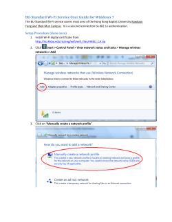


© Copyright 2026