
How to implement an IP telephony-enabled mobile infrastructure Published: 1 August 2007
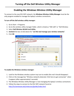
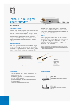
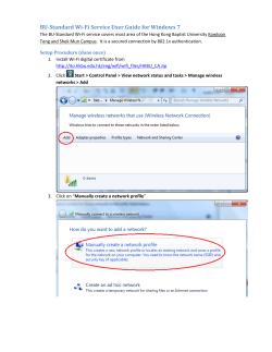
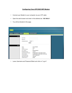
How to implement an IP telephony-enabled mobile infrastructure Published: 1 August 2007 © 2007 SAS Global Communications Limited. Reproduction of this publication in any form without express permission is forbidden. The information contained herein has been obtained from sources believed to be reliable. SAS does not accept liability for errors, omissions or inadequacies in the information or its interpretation. The opinions expressed in this document are based on judgements at the date of publication and are subject to change without notice. All Rights Reserved. Table of contents Introduction ............................................................................................................................... 3 Glossary ................................................................................................................................... 3 What you need to know about mobility ..................................................................................... 4 Autonomous access points ................................................................................................... 4 Lightweight access points ..................................................................................................... 4 Access point deployment – general considerations .............................................................. 5 Voice coverage .................................................................................................................. 5 Signal and bandwidth performance. .................................................................................. 5 Battery life ......................................................................................................................... 5 Integrating mobile users with the network ......................................................................... 5 Quality of service ............................................................................................................... 6 Technology comparisons ...................................................................................................... 8 Implementing a mobile infrastructure ........................................................................................ 9 RF audit and channel management ...................................................................................... 9 Security ............................................................................................................................. 9 Access point deployment................................................................................................. 10 Structured cabling; route planning ................................................................................... 10 Guest access................................................................................................................... 10 The MOS test .................................................................................................................. 11 How to monitor and manage the infrastructure ....................................................................... 13 Dead-zone coverage ........................................................................................................... 13 Roaming.............................................................................................................................. 13 Appliance location detection ............................................................................................... 14 Rogue device detection ...................................................................................................... 14 AP monitoring ..................................................................................................................... 15 Monitoring QoS ................................................................................................................... 16 Fixed mobile convergence - now and in the future ................................................................. 18 Conclusion .............................................................................................................................. 19 About SAS .............................................................................................................................. 20 List of Figures Figure 1-1 WLAN ............................................................................................................................................... 4 Figure 1-2 Routers............................................................................................................................................. 6 Figure 1-3 Mobile infrastructure ......................................................................................................................... 7 Figure 1-4 Technology comparisons.................................................................................................................. 8 Figure 1-5 RF audit and channel management .................................................................................................. 9 Figure 1-6 Upgrading a data WLAN to a converged WLAN ............................................................................. 11 Figure 1-7 MOS test ........................................................................................................................................ 11 Figure 1-8 RF coverage and signal strength .................................................................................................... 13 Figure 1-9 Appliance location detection ........................................................................................................... 14 Figure 2-1 Rogue device detection .................................................................................................................. 14 Figure 2-2 AP monitoring ................................................................................................................................. 15 Figure 2-3 Monitoring QoS .............................................................................................................................. 16 Figure 2-4 Seamless connectivity between fixed and wireless networks ......................................................... 18 Published: 1 August 2007 © SAS Global Communications Limited Page 2 of 20 Introduction Enterprises are becoming increasingly aware of the business benefits to be gained from mobility; greater productivity, cost savings and flexible working. Mobility projects, however, invariably raise concerns about reliability, security and support, particularly when they herald the introduction of voice, video and other QoS-dependent applications. This white paper provides advice on avoiding the common pitfalls of mobility through following a best-practice approach to planning, installing and integrating an IP telephony-enabled mobile network. It also focuses on the main priorities for supporting a mobile infrastructure and outlines proven techniques for proactive network management. Glossary FMC – Fixed/ mobile convergence GPRS – General packet radio services GSM – Global system for mobile communications LWAPP – Lightweight access point protocol MAC address – Media access control Nanocell – Localised cell phone network QoS/CoS - Quality of service/ class of service (AF/EF/standard) RF – Radio frequency rd UMTS – Universal mobile telecommunications service is a 3 generation VoIP - Voice over IP – analogue traffic converted to IP at the router. VoWLAN – Voice over WLAN WAP – Wireless access point WiFi – Wireless fidelity WiMAX – Worldwide interoperability for microwave access WLAN – Wireless local area network Published: 1 August 2007 © SAS Global Communications Limited Page 3 of 20 What you need to know about mobility Configuration of a wireless LAN requires deployment of specialised technology to deliver wireless voice connectivity within any current IT infrastructure. The first area of consideration is enabling wireless network connectivity by use of access WiFi point technology. Figure 1-1 WLAN WAN service Carrier router PSTN / BRI / PRI Firewall VPN Voice gateway router WAN router Web server Application server SAN Default gateway Application server Printer Switch gateway Email server Switch WiFi switch Work station WIP phone UM server Call control server Switch gateway IP phone Laptop Figure 1-1 shows a common configuration of local area network components found in most office environments. Wireless access points (note the WiFi switch highlighted) effectively perform the same task as a standard LAN switch, connecting wireless devices into the core network. Considerable versatility can be gained through utilisation of different types of access point units: internal, external, and those that support directional aerials or antennae when booster coverage is required. Most importantly, however, is the consideration that needs to be given to the differences between autonomous and lightweight access points and how these differences affect network capability and long-term management. (WiMAX, also known as radio broadband, should not be confused with WiFi or WLAN access points. This is the system for point-to-point connectivity over large distances, used mostly by carriers and ISPs where a fixed-line broadband service is unavailable). Autonomous access points Autonomous access points proliferate at the lower end of the market, commonly in use in domestic or standalone situations where the access point itself comprises the configuration and control settings for wireless connectivity. Lightweight access points Lightweight access points, on the other hand, are centrally controlled and managed and, in effect, create a single WLAN over multiple APs. Each AP works in tandem with other APs to deliver a single hotspot. Lightweight access points are controlled by a central wireless LAN controller, a separate switched device sitting on the network. Published: 1 August 2007 © SAS Global Communications Limited Page 4 of 20 When access points are used for voice traffic, or in large areas across multiple offices, increased demands are placed upon their performance. Advanced usage requirements such as voice and video militate in favour of lightweight intelligent access points, as opposed to standalone autonomous access points. Lightweight intelligent access points join together to form one wireless cell and enable users to roam seamlessly between different access points whilst making voice calls. In addition, the central controller adjusts the access point’s power up or down depending on utilisation and coverage required. It also allows a level of intelligence whereby traffic can be switched between access points; the controller enables connection to access points depending on the aggregate level of traffic on the network rather than the proximity of the device to the individual user. Autonomous access points will not work together in the same way. Access point deployment – general considerations Voice coverage Access points provide a lower range of coverage for voice traffic than they do for data. When deploying the protocols required for voice on an existing wireless network, it is frequently the case that coverage is insufficient, even though it may have been faultless for data. In this situation, further configuration may be required in the form of additional access points or directional aerials to ensure the requisite coverage and create a seamless cell. Signal and bandwidth performance. Bandwidth performance suffers as the signal drops; the greater the distance from the access point, the lower the amount of bandwidth available. This may not be of great concern, since many applications, including IP telephony, require only a small amount of bandwidth, so users encounter no problems since their service utilises the available bandwidth, even though it may be minimised. Battery life Devices, such as PDAs or dual-mode devices, which use access points, consume more battery life than traditional devices that connect through the GSM GPRS cellular network. It may therefore be necessary to replace existing devices or upgrade their power supply to maximise running time. Integrating mobile users with the network Mobile users, who sit outside the core internal network, will be connecting through other security and communication gateways for remote access. Traffic going to any external mobile users will pass through the LAN default gateway, where it is directed to the correct remote access communication route. Published: 1 August 2007 © SAS Global Communications Limited Page 5 of 20 Figure 1-2 Routers WAN service Carrier router PSTN / BRI / PRI VPN Firewall WAN router Voice gateway router Web server Application server SAN Switch gateway Default gateway Application server Printer Email server Switch WiFi switch Work station WIP phone UM server Call control server Switch gateway IP phone Laptop The wide area network router, shown on the left in Figure 1-2, takes traffic out through an MPLS network to other sites on the WAN. These can be other company offices or home offices. Through deployment of lightweight access points, it is possible to configure a wireless network to include additional access points in offices other than just the head office. These can all be controlled and configured through a central wireless LAN (WLAN) controller to create a standard WLAN across geographically diverse sites. This allows staff who move between offices to use a standard wireless authentication configuration to gain access to the corporate network and resources. Connectivity would be provided to the mobile devices even though they are at remote locations, routed through the wide area network and back to the central site. Regardless of which office mobile users visit they would always enjoy the same functionality as staff with fixed connectivity to the core internal network. Quality of service Even with the correct configuration and sufficient bandwidth to support all applications, when voice is involved, quality of service must be maintained throughout the network. This will entail the configuration of quality of service, by introducing parameters such as expedited forwarding (EF) used for voice. Expedited forwarding ensures that voice quality is maintained across every device that makes up the local area network and wide area network. The voice gateway router, shown on the right in Figure 1-2, provides PSTN connectivity to the outside world, including mobile devices. The voice gateway router connects to the outside world through a PSTN dial network, using an ISDN 30 (primary rate) or an ISDN 2 (basic rate) line. At this point, as management of the call is handed off to the carrier PSTN network, so control over quality of service is relinquished to the carrier. Carrier networks invariably ensure that quality of service is maintained. The mobile device, if outside the office environment, will be connected through the base transceiver station system (BTS); the latter being the most likely route for mobile traffic. The Published: 1 August 2007 © SAS Global Communications Limited Page 6 of 20 BTS is the national network of mobile masts which house the antennae providing the cellular network. The BTS identifies the GSM, GPRS or 3G device and ensures that the call is delivered to the end node. With some mobile devices using GSM/GPRS/3G and IP they are always connected to the corporate network through the Internet or through a VPN rather than through the voice gateway router that connects to the carrier PSTN network. It is likely that, in the future, significant benefits will accrue from using a single carrier for both Internet connectivity, or landline connectivity, and mobile GSM or GPRS services also known as fixed mobile convergence (FMC). This will be at the point when carriers are able to recognise exactly where devices are located and the medium through which they are connected. This will also signify the arrival of presence. Presence offers connection to the user regardless of location. The network shown in Figure 1-3 shows office users connecting through an IP telephony system, connected to the IP backbone. For internal calls the signal runs across the LAN and is delivered to the user’s IP handset. Figure 1-3 Mobile infrastructure The head office user does not need to track down the number for the mobile device that a remote user may happen to be using at any particular point in time. Simply by dialling the extension number of the intended call recipient, presence will identify the best mode of contact and, if the call recipient is not immediately available, will send a message to the appropriate data device. Published: 1 August 2007 © SAS Global Communications Limited Page 7 of 20 Technology comparisons Figure 1-4 Technology comparisons Feature / benefit GSM GPRS PSTN ISDN 2 UMTS/3G DSL WiFi - 802.11a WiFi - 802.11b WiFi - 802.11g WiFi - 802.11n WiMAX - 802.16 Ethernet - Cat5e - 802.3 - 10BaseT Ethernet - Fibre - 802.3 - 10BaseF Speed 9kbps 56kbps 56kbps 64kps 385kbps 2mbps 54Mbps 11Mbps 54Mbps 100Mbps+ 70Mbps 10/100/1000Mbps 1000Mbps+ Signal distance Cell dependent Cell dependent 33.5Km 33.5Km Cell dependent 7.5Km WAP dependent WAP dependent WAP dependent WAP dependent 51.5Km 165Km 12Km QoS enabled No No No Yes No Yes Yes Yes Yes Yes Yes Yes Yes Figure 1-4 shows the different speed and signal distances available from each of the communication technologies that can be used in creating a mobile network. GSM is fairly restricted, at 9.6 kbps. Whilst certain data applications are possible, they are limited to basic text. Data applications have never been fully developed over GSM networks due to this speed restriction. GPRS constitutes a significant improvement on GSM, increasing the bandwidth up to 56kbps. This is the level at which the last generation of typical modems over PSTN analogue dial networks were able to connect. 56K is adequate for delivery of email text messages, basic screen shots and basic images. This bandwidth is insufficient, however, for feature-rich Internet browsing experiences and use of online applications. Moving further up the scale, in the UK, DSL capability now goes up to 8MB, with even higher bandwidth services soon to be available. WiFi currently offers three technologies: 802.11a, b and g. all of which offer point to multipoint connectivity. In the near future 802.11n is expected to be the next specification ratified for WiFi, with a significant jump up to 100Mbps+. Some access points currently enable the combined use of 802.11a and 802.11g, providing 108 kbps throughput by using both specifications. WiMAX offers high capability at 70Mbps over a very large distance, 5l.5 kilometres. This is purely for node-to-node connectivity; access to data services for a rural community location, for example, or a location not connected to the current DSL infrastructure. Structured cabling, in particular fibre, still provides significant bandwidth improvements over all other scenarios in a local office point-to-point environment. Published: 1 August 2007 © SAS Global Communications Limited Page 8 of 20 Implementing a mobile infrastructure RF audit and channel management The first step in implementing a mobile infrastructure is to undertake an RF (radio frequency) audit of the building or site. Figure 1-5 RF audit and channel management Coverage assessment Figure 1-5 shows a CAD image of one floor of a multiple tenancy office building, overlaid with the results of the RF audit for the floor. At the top end of the building there is no coverage whilst at the bottom there is a high range of cover. This information is invaluable in itself when implementing a mobile infrastructure, but RF audits can be used for more than simply revealing the building’s coverage. Security Understanding the arrangements that need to be made for security is one of the prime benefits of an RF audit. On the right in Figure 1-5 is a table of different access points in use on the site. An apparent anomaly is highlighted in the number of channels in use, focussing particularly on the number of devices using channel 6. In all WiFi protocols there are a limited number of channels available for use. This means that in multiple tenancy buildings there can be WLAN availability issues as WLANs from each floor compete for the limited channels available. In Published: 1 August 2007 © SAS Global Communications Limited Page 9 of 20 this example 18 APs are using channel 6. The impact of this will be that users will experience loss of the WLAN as the APs compete for the same channel. In a shared office environment, or a busy urban area, a number of access points will be in use and it is necessary for a company to determine which access points are its own and which relate to other businesses. This then facilitates access point configuration on a separate channel that is both available and secure from other users. It may be that in office environments tenants will have to agree a combined channel usage strategy to ensure that all their WLANs operate without conflict. Investigation of such anomalies leads to greater precision in access point deployment and eradication of any potential security and WLAN availability issues. Access points can then be fine-tuned to ensure minimum bleed into other tenant areas where coverage is not required; achieved by use of directional aerials and LWAPP controllers to direct access points internally into the building. Access point deployment Fundamentally, an RF audit is essential from a practical perspective; providing an essential appreciation of where and how access points should be deployed. These audits are cheap and cost-effective and will often recoup their investment by reducing the number of access points required for deployment or, perhaps, reducing the need for additional wireless LAN controllers. This in itself would be a cost benefit, not least because the process results in good documentation of exactly what coverage is available, and where (see Figure 1-5). Structured cabling; route planning As well as helping to decide upon optimum locations for access points, the RF audit, through the CAD image and the details of the office building, facilitates route planning for the structured cabling that serves them. Delivering power to the access points is another consideration. If power sockets are not available then a decision might be taken to use power over Ethernet switches to inject power into the structured cabling to keep the devices configured. This allows for a much cleaner and simpler WLAN deployment, quicker moves, adds and changes of APs, as well as providing business continuity options such as enabling the WLAN to be available during power outages. Guest access In terms of providing Internet access for guest users, the options are to give blanket coverage to an entire office area, through an open or password protected WLAN that both staff and guests use (not advised), or as a better option, to provide a secondary password protected network for guests, in the reception area or selected meeting rooms. This second network can be delivered either through additional separate access points, a completely separate WLAN secure from the corporate WLAN, or simply through using the existing corporate WLAN, and using VLANs to create a separate password protected guest network. An RF audit makes it possible to fine-tune and adjust the devices within a network to deliver services down to users. It also assists in the introduction of VoWLAN where existing data WLANs need to be reviewed to assess their suitability to carry voice traffic. Published: 1 August 2007 © SAS Global Communications Limited Page 10 of 20 Figure 1-6 Upgrading a data WLAN to a converged WLAN In Figure 1-6, the left side shows how four access points were initially deployed to provide access point coverage or WiFi access coverage throughout a building. The shading shows the strength of signal that was found in each of the offices at the initial audit. On the right it can be seen that the number of access points has been reduced to three. By using directional aerials and re-tuning the configuration, significantly better coverage and significantly higher bandwidth have been provided throughout the building. The MOS test Quality of service is critical to delivery of voice over a wireless network or VoWLAN. The most effective way to determine the quality of service availability on a network is through a testing system known as mean opinion score (the MOS test) covering all aspects of the network infrastructure, not just individual devices or components or the wireless network. The MOS test monitors the delay, jitter and packet loss across any path, whether a structured network, wireless network or a hybrid. A MOS test will test each network segment to assess its ability to support QoS and identify any device along the intended voice path which may not be fit for the purpose. Figure 1-7 MOS test Published: 1 August 2007 © SAS Global Communications Limited Page 11 of 20 The rankings range from 5 for ‘excellent’ to 1 for ‘bad’; these are used to judge voice quality. 4.34 is judged to be ‘carrier quality’ and users are always very satisfied with this level of service. 3.6 is judged to be ‘business quality’ but some users might be dissatisfied with this quality. 3.1 is where users are really dissatisfied. Figure 1-7 details the results from a MOS test report for a company with six offices, each of which has an IP address, shown on the left, which represents the wide area network router and the local area network core switch. In this test, the overall network was let down by the IP address, 10.8.1.240, second from bottom, as the jitter and data loss were unacceptable. Due to that one address, the whole network failed the test (although 10.8.1.253 also showed considerable loss but this was owing to the 10.8.1.240). In this instance there were two issues affecting the network, the WAN router being set to half duplex instead of full duplex and an incorrect QoS setting on the carrier network. Important to remember is that the MOS test is not specific to the network devices (e.g. access points or to individual mobile devices), it tests each network segment to see if it can support voice traffic. In effect it covers the voice path (i.e. the route a voice call would travel over the WAN and LAN) across every segment of the network; across local area network switches, into the IP telephony device and through the routers. If traffic is to be routed across a wide area network, the quality of service requested must be consistent to maintain the quality of the call and support the optimum number of calls being made. Published: 1 August 2007 © SAS Global Communications Limited Page 12 of 20 How to monitor and manage the infrastructure A number of parameters are taken into account when monitoring and managing the infrastructure. These range from RF coverage and signal strength, through to monitoring bandwidth and application performance and QoS. Dead-zone coverage Close infrastructure monitoring provides the best guarantee of availability for access points connecting to the network, particularly when WLANs are supporting business critical applications or voice services. Figure 1-8 RF coverage and signal strength Figure 1-8 represents the network map of a live infrastructure and shows access points deployed in an office. It also shows how data can be displayed by channel, power level, MAC address or users connected. A large amount of data can be collected from a WLAN for precise management. By virtue of the deployment of lightweight access points there are many benefits. One of the main benefits is that a fault-tolerant WLAN is created. For example, when one access point fails or is not available for maintenance purposes, the other access points located within its vicinity can increase their signal strength to compensate for the dead zone. Roaming It is also important to ensure continuity of service when staff are moving between APs – particularly when using voice applications such as IPT. Should a user walk around the building he or she needs to be able to move from cell to cell without interruption or loss of the call. In the case of data applications, in an autonomous scenario where wireless LAN controllers are not deployed, there will be a small jump in the data as it passes from one access point to another while the data or the connection is re-configured. With most applications the jump may be indiscernible or may take the form of a small pause. Such a jump would not be acceptable on a voice call. This is another major benefit of LWAPP controllers – the hand-off of the voice call between APs. Published: 1 August 2007 © SAS Global Communications Limited Page 13 of 20 Appliance location detection Appliance location detection is a monitoring parameter which facilitates not only precise identification of the location of the access points but also the location of the individual users connected to the network. Figure 1-9 Appliance location detection Overlaid on the same network map as shown in Figure 1-8 are the devices, within the network, which utilise the access point configuration. In a lightweight access point system, the system will re-configure itself to spread additional user connections across access points, should a cluster of users access one particular access point; their demand on the WLAN can be load-balanced. Users will not be accommodated simply by the nearest available access point with the strongest signal. The network will be spread to deliver services via a number of access points available in the area. Appliance location detection also enables the identification of rogue devices. Rogue device detection Figure 2-1 Rogue device detection Published: 1 August 2007 © SAS Global Communications Limited Page 14 of 20 The device indicated in Figure 2-1 is transmitting on the WiFi network, and has been introduced outside the scope of the internal corporate network. Identifying rogue devices is important for a number of reasons: Through this process, access points can be traced that may have been configured in the office area without approval as well as staff members using their laptops to share the corporate WLAN. As an example, there was a hotel chain which had a central agreement with a carrier for deployment of hot spots at each location. The management team was aware that individual hotels had in the past signed up to different agreements with different carriers on an individual basis. For consistency of presentation to customers and guests it was important for the management team to ascertain if the group was offering more than one scenario or more than one access point configuration so that the standalone hot spots could be identified and removed. Whilst offering a uniform message to a selected target audience is important to companies operating within certain sectors, there is one area of rogue device detection of concern to all businesses and organisations: security. In the corporate environment potential security risks, posed by rogue devices, have to be investigated. It may simply be a case of a device on another floor in the building over which the company or organisation has no jurisdiction that may be affecting WLAN availability. A company needs to be able to locate the access point and identify who is responsible for the AP in order to reach a resolution. Companies in multiple-tenancy buildings will need to discuss a channel management strategy with other tenants to ensure that all their respective WLANs operate without issue. AP monitoring Figure 2-2 AP monitoring Access point monitoring is not only an invaluable trouble-shooting mechanism, identifying problems and opportunities as dealt with in this section, but can also provide input for trending and capacity planning. It can help identify the need for office relocation, expansion, contraction or simply employee relocation, whilst, at the same time, enabling an organisation to assess the impact of such adjustments. Published: 1 August 2007 © SAS Global Communications Limited Page 15 of 20 Access point monitoring can also help ensure a level of change control and policy enforcement, particularly concerning lightweight access points. Whilst this will be coordinated through the wireless LAN controller it can also accommodate changes such as software upgrades to ensure consistent levels of service, offering seamless levels of connectivity, regardless of which access point users connect into. Understanding the utilisation levels of different devices is an additional benefit that comes from the process of monitoring the access points and ensures adequate end user performance. Although the fundamental logic of access point deployment may initially have been sound, organisations and users are dynamic, and usage patterns change over time. Redeployment of access points is necessitated most commonly by office refurbishments, staff changes or application changes. It is a common occurrence that some access points are then under-utilised whilst others are stretched. Monitoring QoS The prime objective of monitoring quality of service is to ensure that it is maintained long-term and understand the average as well as peak QoS demands. Figure 2-3 Monitoring QoS The test shown in Figure 2-3 was conducted to monitor the quality of service across an international wide area network infrastructure over a three-day period (from 27 April). At the start of the period, the system failed, dropping below the acceptable threshold for quality of service delivery At the top, in blue, is the overall MOS test result. Peaks and troughs are in evidence throughout at any period of time. The quality of service is varied and as the peak shown on the far top right-hand side shows where quality of service reached the threshold beyond which voice quality is affected. The MOS test shows the average utilisation and performance as well as peak demand and shows that both were being accommodated within the QoS parameters on the WAN and LAN.. Published: 1 August 2007 © SAS Global Communications Limited Page 16 of 20 Configuration changes were made through the first day, with demonstrable improvements; packet loss, jitter and delay were all reduced and an acceptable level of service was established. In this example, these issues were caused by incorrect router configuration, i.e. where some legacy routers did not support QoS and incorrect WAN configuration. Nonetheless there were still peaks, outside the threshold parameters. On the afternoon of the 28th there was a spike, a peak in the delay, above and beyond the threshold. Again, in this example, the peaks were caused by testing that was being undertaken on the video conference units in order to set the correct QoS parameters. By monitoring such occurrences longer term, user’s expectations can be managed; interim adjustments can be made to correct problem issues before the overall quality of service is lost on the network. Ongoing monitoring also permits time-stamped remedial investigations if users complain of voice quality problems after implementation and any changes to the voice path on any segment of the corporate network. Published: 1 August 2007 © SAS Global Communications Limited Page 17 of 20 Fixed mobile convergence - now and in the future Figure 2-4 Seamless connectivity between fixed and wireless networks Fixed mobile convergence (FMC) is the phrase used to describe seamless connectivity between the fixed and wireless network. This is now a dominant trend within the telecommunications industry. FMC takes place when a mobile device can access corporate data or applications irrespective of whether it is connected via a fixed or wireless network within or outside the office premises. This is increasingly being achieved through dual-mode (GSM and IP) mobile handsets. Dualmode is now commonly advertised as a feature of PDA devices and mobile phones; meaning they are capable of GSM, GPRS 3G and WiFi connectivity and can hop from one network to another. The ultimate goal of fixed mobile convergence is to optimise transmission of all voice, video, and standard data communications, across any device or location, and over any available network. It is likely that, in the very near future, devices will appear on the market that can connect and be switched between wired and wireless networks without any user intervention. Such devices will not only make life easier for mobile workers and people generally on the move but they will also facilitate the use of presence. Presence is where the systems can not only determine the multiple ways in which a user is able to communicate, but will also work out the best mode of communication with another user by assessing the communication status of the other user. If a user is not in the office when another user dials their extension number, the telephone system will automatically recognise that they are not available at that time and select the best contact medium, which may be a call to their mobile or home phone or an email. Presence assesses a user’s availability from data entered in their ‘diary’ to determine the best method by which to communicate with them at any given point in time. The user may pick up a telephone to make the call but the core system will automatically recognise that the person being called is not available and determine the best method to communicate with them in the quickest possible form, that most likely to elicit a response. Published: 1 August 2007 © SAS Global Communications Limited Page 18 of 20 Conclusion Currently, there is no single technology solution designed to facilitate mobility in every scenario. The market is characterised by combinations of different technologies being used to produce combined solutions. Seamless connectivity in different mobile scenarios is thus available and deployable. The decision whether or not to implement an IPT-enabled mobile infrastructure should be informed by a number of well-considered steps: Review business drivers and demands for IP telephony-enabled mobility; identifying what is really driving the need for mobility to be connected through the internal IP telephony system. Identify and test solution components and their interdependencies. It is important to assess the entire network infrastructure for quality of service and not simply the individual mobility solution, whether that is the wireless LAN, a PDA or connectivity through a GPRS device. The MOS test is the perfect benchmarking assessment for network readiness for mobile voice. Conduct user group trials to test and develop the solution before it is finally deployed. Set limited expectations for the deliverables from fixed mobile convergence. Whilst perfect anywhere-anytime connectivity will be available in the near future, being the goal of the industry, it is yet to arrive and expectations should be managed accordingly. Ascertain whether or not the existing carrier used by the company is able to support fixed mobile convergence and gain an understanding of the road map to which they are working. It will become increasingly important to work with a single carrier who can support the many demands that may be put upon a converged network infrastructure. From wireless hot spots, to the Internet, and onto the cellular dial network, the ability to provide seamless connectivity will militate strongly in favour of single carrier agreements. Understand the current carrier hardware and application limitations. With a wide variety of connectivity options comes a huge variation in bandwidth and signal distancing. Ensure ease of use. Currently the solution is not easy to use and this could create a barrier to adoption amongst intended users. The launch of the Blackberry created immense excitement since users could simply turn on the device and receive emails instantly. They would send an email and it would go just as instantly, with no need to invoke a third party package or try to synchronise or connect to another system such as a VPN, before they could actually use the system. Ease of use means instant adoption and this could be the deciding success factor when an IPT enabled mobile infrastructure is implemented. This is very, very important to remember. Published: 1 August 2007 © SAS Global Communications Limited Page 19 of 20 About SAS SAS Global Communications is a major provider of managed and professional network services. The company provides consultancy and implementation services to design, build and manage converged IP networks for enterprises of all sizes. Since its inception in 1989, the company has successfully delivered more than 2000 highly commended solutions, to a broad spectrum of clients including many renowned brands, such as Coca Cola Enterprises, The Body Shop International and Millennium and Copthorne Hotels. For more information contact: SAS Global Communications Limited SAS House Blackhouse Road Colgate, Horsham West Sussex RH13 6HS Tel: +44 (0) 1293 851951 Fax: +44 (0) 1293 852200 Email: [email protected] www.sas.co.uk Published: 1 August 2007 © SAS Global Communications Limited Page 20 of 20


© Copyright 2026