
HANDLING! What It Is And How To Get it TRIES INC ADDCO INDUS
HANDLING!
What It Is And How To Get it
ADDCO INDUSTRIES INC.
Roland de Marcellus
1596 Linville Falls Hwy
PO Box 217
Linville, NC 28646
1-800-338-7015
ABOUT THE AUTHOR
Roland de Marcellus, founder
of ADDCO Industries is a
graduate of Georgia Institute
of Technology and has been in
the car suspension business
since 1960. Some of the passages in this book have been
taken from technical articles
he has written for car
magazines over the years.
© copyright 2005
FOREWORD
Learning is the way we have advanced since our hunting and
gathering days, but what many lose sight of in the worlds of
Modern Academia is that, regardless of the diplomas you may
earn, if you only learn what others teach there can he no
progress.
Too often impressive titles, corporate logos, and academic
recognition make the individual feel he must only follow, as his
mind surely cannot create beyond what the great established
institutions that surround him have done. But while they
exchange, copy, and formalize knowledge, it is the individual’s
ability to think that creates and pushes forward the frontiers of
man’s knowledge.
I trust that the following work will give you the will and
encouragement to use your mind to add to our wisdom and
accomplishments.
“If I have seen further than others, it is because I have stood
on the shoulder of giants.” - Sir Isaac Newton
INTRODUCTION
Chapter I
Where is the problem?…………………………..2
On the strait-away
Passing
Cornering
Acceleration
Braking
Ride
Road Feel
Chapter II
Your Goal………………………...………….....6
Highway Sedan
Town Car
The Hot Street Cars
Ralley
Grand Touring
Sports Road Racer
Slaloms
High Powered Sports Classes
Van and Motor Home
Ambulance
Chapter III
Dynamics of Cornering………………………10
Experiment
Geometric Steering Effects
Roll Axis
Throttle Braking Effects
Cause and Effect Summary
Chapter IV
The Equipment………………………………..31
Tires
Wheels
Spoilers
Anti-sway Bars
Urethane Bushing End-links
Adjustable Anti-Sway Bar Systems
Urethane Mid-section Bushings
Traction Bars
Camber Compensators
Panhard Rods
Shock Absorber
Spring Boosters
Ballast
Springs & Lowering
Chapter V
How stiff?……………………………………. .64
Calculations of Body Roll
Tire Overloading
Chapter VI
Choosing a Chassis…………………..………….72
Chapter VII
High-Speed Driving……………………….…….80
Chapter VIII
Active Handling and ABS
Chapter IX
Off-Road
Chapter X
In Summary……………………………..………89
HANDLING
What It Is – And How To Get It
Handling is control, and the more control you have of your
vehicle, especially in adverse conditions, the better the “handling.” If
run slowly enough, any vehicle will negotiate almost any adverse
conditions whether it be bumps, curves, or what have you; for this
reason SPEED must be a basic assumption in discussing handling.
Thus, if car “A” does any given maneuver quicker than car “B,” it
will be credited with having better handling. Inversely – at any given
speed, the better handling car is the safer – frequently much safer.
This is undeniable. Although engine power is definitely a part of
handling, it is such a separate and distinctive part of a car’s nature
that it is not treated herein except where it relates directly to its effect
on chassis performance, due to its weight, or to its effect on driven
wheel adhesion.
The popular, yet much maligned, “soft ride,” is also a part or
handling. Although taken to an extreme in many cars, one can
visualize a situation in which a softly sprung car could be driven at a
higher speed across an extremely rough road than a hard sprung
sports car, which would not only bounce out of control, but would
be more likely to damage itself or put an unacceptable strain on the
driver.
A Firebird owner called me once and said he had done
“everything” he could to his car; stiffer springs, extra large swaybars,
stiffer shocks, big tires with 30 some lbs. Of pressure, but his wife’s
Buick could still beat him into town and on a winding old country
road. I explained that if the car’s suspension resiliency is greatly
reduced, the car can no longer absorb rough or uneven surfaces, thus
greatly reducing the ability of the tires to stick to the road.
Obviously, handling must be a compromise among many
facets of automobile behavior; and no two people, given their exact
choice, would choose the same combination of virtues and
weaknesses in their own car. For this reason, we will outline the most
important areas of handling and show the effects of the various
modifications available on the market. In this way owners can weigh
their personal preference in modifying their car so as to have it
perform just the way they want it to.
1
CHAPTER I
Where Is The Problem?
ON THE STRAIGHT-AWAY
This is one time when you want nothing new to happen; you want
to just go on zipping straight down the freeway steadily and comfortably.
With our ever increasing freeway system, this is becoming increasingly
Important to many people, even though it may not be too much fun.
Unfortunately, many cars don’t just keep zipping down the freeway. They
wander, float up and down, pitch fore and aft like a see-saw, vibrate, or need
constant corrections to keep them in their lane. Perhaps the most
unfortunate aspects of modern cars is the false sense of security they give,
when in actuality their high speed maneuverability in an emergency is
extremely low.
PASSING
We list this separately, as it is a unique type of maneuver; from a
fairly high constant speed; you open the throttle as you execute a tight “S”
curve. In many of today’s cars, this can be an unnerving event; just as you
establish overlap on the other car, your vehicle seems to want to continue its
pivoting effect set up in the “S” curve. You must apply a little correction,
then quickly correct so you will not leave the road or hit the passed car.
Many highway accidents are caused by loss of control when trying to pass.
CORNERING
This is the first thing most enthusiasts think of when you mention
“HANDLING.” Poor cornering is always unpleasant and, not infrequently,
dangerous. When you steer the wheels, you would like the car to follow
them with no fuss. Only a few of the special-order performance cars sold
today will do this. For this reason, salesmen on demonstration rides will seek
out railroad tracks to show the soft. Ride, straight-aways to show off power,
but never a sharp corner to push it through! Body lean, tire squeal,
understeer, wheel spin, etc., are so much a part of today’s cars that most of
the population simply consider them due to “driving too fast.” Thus, there
is little incentive to invest the extra few dollars to correct it. Things have
improved somewhat since 1974-75. They include extra stable suspensions
with better shocks and anti-sway bars on their top-of-the-line models.
Regrettably, these are installed only on luxury models.
2
Since the early 80’s handling has become worse with most cars going to
front-wheel-drive. The problem is more insidious as many of these cars handle
relatively flat, and accelerating in a curve no longer spins a wheel, and the newer
tires do not start to sing as you approach the adhesion point. If pushed too hard
though, there is suddenly massive understeer, as the front tires slide. If the brakes
are hit, the light rear comes around, and it’s gone.
If you look at the skid marks on the interstate, you will now see many marks
made by small cars where the tire marks cross one another, indicating the car was
spinning, all wheels on the pavement and no other marks in the area. Indicating a
sudden braking or passing maneuver caused the driver to simply lose it.
Statistically most interstate deaths are single car accidents. Many accidents
that start as single car accidents, involve others as they cross the median. There is
no excuse for any car to lose control on an interstate at any speed (except for
drivers that fall asleep), but it happens more and more often, simply because the
cars are not stable enough to retain control after a sudden swerve or braking
maneuver. Mini-vans, one would expect to be handier and more nimble, than the
older larger vans, but the handling is not any better, but a great deal worse. Some
are out right dangerous even in everyday driving, due to its lack of stability.
ACCELERATION
Because the car body is accelerated, not by the engine, but by the
suspension, it causes some strange effects. On corners, the car body is being
acted on by the weight of the car, the thrust of the tires, the lateral side thrust of
the cornering force and the torque of the engine. On rough pavement, the
wheels can hop, break traction, grip again and hop, and so on, giving a
hammering effect; and on corners can cause the rear end to slide.
BRAKING
Here we have the same problems as in accelerating, except that the drive
axles want to drag and rotate with the wheels instead of against them. As one
usually has less choice about whether to continue braking or not, than to
continue accelerating, the consequences can be worse. Dive, an unpleasant
feeling puts more weight than ever on the front tires, thereby, reducing braking
and steering efficiency.
RIDE
Many people feel that the stiffer the springs, the better the handling. Not so.
In the extreme case in which the frames are welded to the axles (like in many
Dragsters), everything will be fine if the track is perfectly smooth (as for
Dragsters); but if you drove such a car on the road, every little bump would
break the tires loose from the pavement, breaking the adhesion. In effect, your
3
whole car is “unsprung weight.” Furthermore, on uneven pavement only
three tires would ever be on the ground. This explains the expensive and
carefully built independent suspensions on the all-out racers, such as the
Formula cars.
ROAD FEEL
Basically, this is experiencing the sensations of driving. Naturally,
the enthusiasts like it, and the family man {and especially women} who
think a good car should feel like his favorite TV armchair, dislike it. As the
enthusiasts are outnumbered (what is the ratio – 50 to 1?), manufacturers go
to great lengths to do away with road feel. This is tragic, for one can feel
impending danger long before one sees it start to happen – if you are
allowed to sense what is happening, as well as just sit there and look out of
the windshield. Slicker pavement, a failing tire, uneven drift, poor surface,
failing brakes, or poor steering, the safety margin on curves – all are sensed
by way of the steering response, the brake sensitivity, the seat itself, and the
visual awareness of small, but telltale movements, of the front of the car.
(This is the purpose of racing stripes in front of the driver on the hood. So
now, they put them on the roof, or even worse, on the rocker panels, or
around the trunk.) In most of today’s cars, there is so much irrelevant
movement in he car body on its mushy suspension, and so little feel in the
power steering and power brakes, that only the sudden movement of the
countryside tells one that something bad has already started to happen.
It matters not if you own a large luxury sedan or a sports car; any
of the foregoing problems exist to one degree or another. And they can all
be improved a little, or a great deal, with a little ingenuity and a few dollars. I
said a few dollars. If you go buying all the most expensive accessories, tires,
etc., available without carefully weighing your initial problems, the most
direct cure, and your own goals and compromises, hen the sky is the limit.
Production cars are not that bad; they are just built for people that neither,
know nor care about handling. Of course, the builders are reluctant to spend
any money on things that will not help the cars sell, and which, even in a
small way, might detract from the ultra-soft “sitting in a tin cloud” ride that
sells so many cars to the intrepid.
Remember, that an extra dollar spent on building a car would cost
the producer $1,000,000 or more per year. In an earlier edition of this book
I said, “If handling were less nebulous, and could be measured on a machine
like horsepower, and then advertised in a neat competitive number, things
might change.” This has actually come to pass, and most car reviews now
give the “G” factor of skid pad tests. Many of these are in the 80’s. These
tell you that it stuck up to that reading but does not tell how out of shape
and difficult to control, or how uncomfortable it was, but at least it gives
some indication what to expect. A year or two ago, some well set up, low
4
priced sedans were raced against a number of big engine Corvettes on a well
known West Coast race track. It was a toss-up. The sedans cornered “at
least as well” and had almost as much acceleration. So, there it is. That’s
what you can do by knowing what to do and what equipment to use.
So much for what you wish would happen and what, on the other
hand, usually does happen. The next step is to honestly evaluate how good
or bad your car is in these various areas of handling. Despite the ads, the
different suspensions used, and what the respective fans say, cars are all built
to compete in the same markets, and must sell at competitive prices; it is no
surprise that they have the same handling weaknesses. In varying degrees to
be sure, but the difference is not as great as you might think. A little work
on the worst would make it handle much better than the best.
5
CHAPTER II
Your Goal
Now decide what kind of a machine you want. More specifically,
how do you want to be able to use it? There are a number of car types, one
of which represents an enthusiast’s objective. Frequently, it is a blendcompromise if you will – of two or more kinds. Detroit merchandisers have
a field day every year dreaming up what they feel are exciting new image
names that relate to one type or another – and their penchant for putting the
wrong name on the wrong car is uncanny. A Cadillac is a comfortable car
for long distance trips; so, why do they call it a “Coupe de Ville” (French for
town coupe)? Try driving one in a French town! I can think of more suitable
cars to name after the French road race, Le Mans, than a middle of the line
Tempest and now a bottom-of-the-line, entry-level oriental import. But to
most knowledgeable car buffs, cars do fall into some common sense
categories that are good to think about in the light of one’s own taste. Most
cars will fall into one of these groups – Highway Sedan, Town Car, Grand
Touring, Hot Street Car, RaIly, Sports Road Racer, Slalom, High-powered
Race Cars, Oval Track Cars, and the like, are not discussed here, due to their
special left-hand-only turns, they are never set up to be all-round good
handling cars, which is our goal.
HIGHWAY SEDAN
This is the intermediate to large size cars used primarily for long
distance driving. This is the type of car that Detroit has prided itself in until
the gas shortage came on the scene. They do their job very well, and yet,
many show up with obvious handling problems. For this type of driving
there are a number of important requirements. Directional stability is the
most important due to the fact that nearly all one’s life is spent riding at high
speed on straight or gently curving highways. Resistance to cross winds is
essential.
Powerful engines are not as important as they used to be, as the
time of two-lane highways full of underpowered trucks that had to be
constantly passed, is now seldom encountered. Sufficient power for
acceleration ramps and good gas mileage is the best compromise now. Antisway bars and shocks are the most important here.
TOWN CAR
A comfortable and usually an intermediate size vehicle in which I
good acceleration and handling are the sought after elements. An unstable
car becomes very tiring to drive in urban areas, as the constant corners
require slowing to as little as 8 m.p.h. to avoid uncomfortable lurch and tire
6
squeal. The accompanying front tire wear is another important problem.
There are other factors also if the car’s poor handling requires slowing from
30 to 10 m.p.h. for a typical city block turn instead of being able to take it at
20 m.p.h. You will use twice the gas accelerating back to 30 m.p.h. as you
would if your car handled well-and in so doing, you will, thus, cause twice
the pollution also! Another little asset is that you look like you’re in control.
I saw a young driver make a turn onto State Street in Chicago’s downtown
Loop district. He was not going fast – 10 or 12 m.p.h. at most – but he
cranked the wheel over especially fast to give clearance to an oncoming wall
of pedestrians. His Rambler, equipped with light duty tires and no anti- sway
bars, lurched precariously and looked so out of shape, a traffic cop signaled
him over for “reckless driving.” It helps your case a great deal if an officer
must admit that he did not hear your tires squeal. The section on anti-sway
bars is the most pertinent for the city driver.
THE HOT STREET CARS
Perhaps those are the most sought after type of car by the young
enthusiast. These small or intermediate size cars are set up to be as powerful
as possible with numerically high rear end ratios to give the fastest
acceleration possible. These drivers frequently did not care about handling,
but with cars like the Olds 442 introduced in 1965, the trend was set to
power-plus-handling capabilities. In the 70’s the finest example of this type
was the highly successful Firebird and Camaro. Available with a full range of
engines and special suspensions, it offered the best sport chassis for the
enthusiast to work with. Regrettably, it was destined to fall victim to the
down-sizing program required by the gasoline mileage goals of the
government. For this type vehicle, special attention should be paid to the
section on traction bars and anti-sway bars. In the case of engine swaps
where heavy engines have been put into light chassis, rear anti-sway bars,
front shocks, and springs are where there one’s attention should be given.
RALLY
Whether it is a small sedan or sports car, no exceptional demands
are placed on the vehicle itself, but if it is not fun and rewarding to drive, it
has failed. Your personal driving taste should be the guide here.
GRAND TOURING
One visualizes a fast, extremely good handling car used for high
speed cross-country touring; a car that must maintain speed comfortably on
narrow, rough, and winding roads. Spreading suburbia, super highways,
speed traps and the 55 m.p.h. limit on back roads, have relegated this –
perhaps the most thoroughly rewarding type of driving – to those fortunate
enough to afford insurance that escalates with every new speeding citation.
7
The grand touring type car would be set up similarly to the next
classification.
SPORTS ROAD RACER
These are sports cars or intermediate sports-sedans. Set up
primarily for racing on road courses. Typical of these are the SCCA
production racer. As they are highly competitive and safety oriented, they
become ill-suited for street driving due to the elimination of lights, etc. Of
only moderate power the winning cars are the cars that handle the best and
that have the needed endurance. As these races are frequently long, engines,
tires and drive-trains must stand up to all-out racing for hours at a time.
Tires, anti-away bars, shocks, and other suspension components, must be
delicately balanced.
SLALOMS
The competition of cars against the clock in a short tight circuit is
not only challenging for the driver but quickly separates the good handling
cars from the bad. Usually laid out about pylons in an unused airstrip or
parking lot, the cars’ suspensions are wrung out more thoroughly in a good
slalom course than on many road courses. As cars are run usually only one
at a time and comers are marked by plastic pylons instead of the trees,
gullies, and other “natural hazards” of a road course, cars are frequently
pushed to and past their adhesion points. As a misjudgment means only lost
points, rather then a demolished car or personal injury, even the neophyte
can push his car to its limit; thus, the demand for handling is perhaps more
pertinent in a good slalom contest then in a sports road course where engine
power, endurance, and the interference of other contestants all become
factors.
An unusual set up for these cars favored by some drivers is extra
firm rear anti-sway bars. The purpose is to cause oversteer and the ability to
slide the rear out. Thus, pylons may be passed close by with the front wheel,
and the rear will oversteer clear of it. Thus, part of the steering is done with
the rear of the car.
One important feature of slalom cars is that most can and are
driven on the street also. Shock absorbers are less important than in the
sports road racers, as speeds are never as high; the surface is usually regular.
Panhard-rods and anti-sway bars are more important in this case.
HIGHER POWERED SPORTS CLASSES
These are sports road course racers. With the reworked or special
engines, these cars are light with a lot of power and are set up differently
from the lower sports classes. With a lot of power fed consistently to the
drive wheels, oversteer would be a constant problem; so, the trend here is to
8
put more and more of the cornering effort on the front wheel. For these
cars the importance is for front anti-sway bars, Z-bars, and Panhard-rods.
This set up would make a clumsy streetcar at best.
VAN AND MOTOR HOME
Less exciting, maybe, but more important from a practical point of
view are these everyday workhorses. As their drivers use them for long
periods traveling on the highway, it is important that they not be unpleasant
or tiring to drive. Their large size and higher C.G. give these vehicles
inherently inferior handling characteristics; thus, extra care must be taken to
make them handle well. Poor highway tracking and clumsy cornering are
their problems. Anti-sway bars and good shocks are what they need the
most.
AMBULANCE
Although usually based on van and small truck chassis, they are
listed separately, as they are used so differently – usually heavily loaded with
extra body and equipment. They are driven as fast and as hard as possible –
well above legal speeds most of the time. The best handling possible is an
absolute essential: It not only increases safety, but also increases the possible
speed that it can be driven. A reasonably good ride must be retained for the
comfort of the patient being transported.
With the foregoing groups in mind, as you read on pay particular
attention to the section that applies the most directly to the type of car in
which you are interested. Even if you are setting up an H production sports
car, you will still want to make your go-to-work sedan a pleasant car to
drive. So first, we will see what can be done with a typical car as it comes
from the showroom.
9
CHAPTER III
Dynamics Of Cornering
Before one can understand why a car handles badly, or before one
can understand what will improve it, one must be able to visualize in one’s
mind every force that is developed and how every part of the car reacts to it.
Thus, as one experiences certain undesirable characteristics of the car’s
behavior, one can easily reason out both the cause and the cure. The reason
that there is so much misinformation and, to be frank, ignorance, on the
subject even among people in the parts and mechanics business, is that they
have never bothered to think through the mechanics of the thing; and thus,
they can only repeat the rumors, tales, and erroneous ideas they hear from
others or that are pushed by car merchants or specialty equipment salesmen.
Think it through step-by-step and come to your own logical solutions and
act on them: you will develop a better car for less money than your
competition that relies on grease-monkey hearsay.
The terms “Understeer”
and “Over steer” and “Drift” must
be completely understood and
visualized in order to understand
any discussion of automobile
handling. The terms deal with the
phenomenon of a tire creeping
sideways as it rolls if there is a
lateral force pushing it from the
side. The speed of this creep or
“drift” as it is called, depends on
the amount of lateral force, the type
of tire carcass and its rigidity, the
tread compound, the air pressure,
and the load bearing down on the
tire. The greater the load the more
the distortion and, therefore, drift.
This all assumes one has not
reached the adhesion point. The
adhesion point is the point at which the lateral force pushing the tire is equal
to the friction between the tread and the road surface. If more lateral force
is added, then in addition to the drift, you have slide. The more weight you
have on the tire, the higher the friction and, therefore, the higher the
adhesion point. Extra weight on any given tire will increase both drift and
adhesion force.
Obviously the tire adhesion patch is motionless on the pavement,
anyway, up to the adhesion point at which time it slides. But obviously also,
the rear end of the patch is constantly being picked up and the front is
constantly being laid down. This is more visually evident when one watches
10
a tank-tread in motion. The principle is the same, but in corner the rim and
thus most of the tire is pushed outward of the adhesion patch. As the tire
rolls the adhesion patch is laid down, not in front of the previous location of
the adhesion patch, but a little further out more in line with the forward part
of the tire which is centered on the rim. This is where the new tread that is
being laid down is coming from. A gust of wind that pushes the front of a
car to one side, although acting just briefly, causes the same effect and
requires steering correction. Waggle the rear of a sedan with your hands as
you watch the rim over the adhesion patch; see how much the rim can
move.
Figure No. 1 shows the various forces working to distort the
portion of the tire near the adhesion patch. The rim, and thus the car, will
follow the direction in which the patch is being laid down just as your body
follows the direction in which you place your next step when you walk.
Flexy sidewall radials will have greater drift, sometimes referred to
as slip angles, than will hard multi-ply bias tires. More air pressure makes the
tire less distortable and thus the rim can move out away from the adhesion
patch less. This extra air pressure reduces tire drift.
Understeer and oversteer refer to the relationship of front versus
rear drift. If the front tires have a higher drift speed than the rear tires, the
front of the car is led out of the turn; therefore, making the car describe a
larger radius curve than was steered by the driver and indicated by the angle
of the front wheels, this is understeer. If the rear tires drift faster than the
front tires, thereby bringing the rear of the car out and pointing the front of
it in toward the center of the curve, one has an oversteer condition which
will make the car describe a smaller radius curve than was steered. The
foregoing assumes the tires were not sliding, but only drifting. If the front
had started sliding, it would e referred to as “mushing out” or some other
such term, or to “spin-out” if the rear tires had slid. The terms give the idea
that the front slide is more gradual than the rear slide. It is, and for an
obvious reason: as the front slides out, it increases the radius described by
the car, thus, decreasing the lateral centrifugal force; thus, reducing the slide
tendency so it can teeter along just beyond the adhesion point in a kind of
equilibrium. Whereas, when the rear starts to slide out, it decreases the
radius of the path of the car throwing it into an even tighter turn. Thus,
greatly increasing lateral G forces that cause it to slide even faster. Only fast
steering out of the front end by the driver will avoid the car from spinning
out. It is this fact that the Detroit designers use (in the name of safety) to
justify building of the clumsy, nose-heavy vehicles for which they have been
known. The black marks of sliding front tires over the outer curbs of almost
every clover leaf is ample evidence of the foolishness of this philosophy
when carried to some of the present extremes.
In the case of a sudden turn, the front tires can easily be heard to
squeal as they become temporarily overloaded as they try to snap the front
of the vehicle around. As this docs not happen without some
11
additional drift outward from the direction in which the front tires are
pointed, understeer is experienced until the pivoting speed of the chassis has
caught up with the function of the speed and angle of the front tires. At this
point, the car will continue to circle around and around at a given number of
circles per minute; and, incidentally, it will be doing the same number of
pivots per minute. To better visualize this, imagine this circling car in space.
It would be referred to as a “tumbling in orbit.” The orbit is the circles it is
doing on the parking lot, and the tumbling is the constant pivoting of the
car necessary to keep its front end leading. In this case, the car “orbits” in
the same manner as the moon with its orbits coinciding with its rotational
speed. Thus, both the moon and the car keep the same side toward the
center of the circle all the time.
On coming out of the curve, the reverse happens. The front tires
are steered out of the curve, and the pivotal inertia of the chassis tries to
push them sideways into the turn. As this force is in opposition to the
centrifugal force of curve, front tire drift is suddenly reduced, and an effect
called terminal oversteer occurs. These effects are not the fault of tires, or
other aspects of the suspension, and cannot be cured by them, but they are
magnified or minimized by the dynamic weight distribution discussed later.
These ill effects can, though, be absorbed by a well set up car through large
capacity, low-drift tires, etc. Let’s study dynamic weight distribution, or
more correctly, the mass distribution and how it affects initial understeer
and terminal oversteer.
As can be seen from the fact that vehicle weight increases a tire’s
drift and decreases its sliding, drift and sliding; and therefore, oversteer and
spin-out (and understeer and mush-out) are caused by different effects and
have different cures. Remember though, that as weight is increased, so is the
mass of the vehicle; so, it develops more centrifugal force for any given
radius and speed. Theoretically, this will increase at the same rate as the
increased adhesion; but other things enter into it, such as the weight-tounsprung-weight ratio, etc., that will effect the result.
EXPERIMENT
In the middle of an empty parking lot, crank in a one-half turn on
the steering wheel. Put the car in gear, and drive it five miles an hour and
when car completes the circle, you will have returned to your original
position. Have someone measure the approximate diameter of the circle.
Try it again with the same amount or steering turn at 20 m.p.h. and 30
m.p.h. being sure to use a steady gentle throttle. If your car describes a larger
circle as you increase the speed, it understeer; if it describes a smaller circle,
and you end up closer to the center than where you started, it is
oversteering. If it is set up to steer neutral, you will still end up slightly
12
further out than you started because the car still drifted, but it drifted evenly
front and rear; thus, the difference was not magnified by the car being
pointed inward or outward by the drift. If it is set up to oversteer slightly –
just enough to offset the drift- you will end up just where you started. This
slight oversteer condition is what most drivers seek; it means that the car
goes exactly where it is steered. Try this experiment again in the rain; at slow
speeds the results will be the same due to the fact that the slicker pavement
is reducing the adhesion, but not the drift in the tire. At high speeds you will
easily pass the adhesion point, mush-out, or spinout, or slide out-sideways.
13
People are always concerned about their car’s weight ratio in
relation to cornering: a 50/50 weight ratio being considered ideal. Actually it
is only an advantage in that the same tires and pressures can be used front
and rear which, of course, simplifies the tire rotation. Furthermore, many
racing clubs require equal size tires on all wheels in the sports car classes. If
a car is engineered out completely (and very few are it seems), and the
weight distribution, track width, roll stiffness, tire size and pressures, spring
rates and other factors are all taken into consideration and are proportioned
correctly, then weight distribution need not be balanced, and in itself is not
important.
An early example of this is the Citroen DS with engine,
transmission and drive train weight all over the front wheels and no rear
overhang. The percentage of weight on the front wheels is far greater than
on any domestic car, and yet, it is a beautifully balanced car in a really hard,
high-speed turn. This has been done by wider front track than rear, heavy
proportioned, front and rear anti-sway bars, hydraulically proportioned
“Spring Rates” (It is an entirely hydro-pneumatic system.), and increased
front tire pressures (although the tire size is the same).
The EI Dorados of the time on the other hand, had the extra
front-end weight of the front-wheel drive layout. A heavy front anti-sway
bar, similar track and tires (front and rear), and at speed in sharp corners,
develops what even broad-minded magazine test drivers refer to as
“massive” understeer. This is an excellent example of two similar types cars,
one engineered out for handling performance and the other built with no
special regard given to its control capability. The heavier a car, or end of a
car, the greater is the centrifugal force generated on any given radius corner
at any given speed, but so is the weight of the car forcing the tread
compound against the road surface. Thus, weight -or lack of it – in itself is
not harmful to cornering provided all parts of the car, or that end of the car,
are proportioned properly.
The Delorean that has 65% of its weight on its rear wheels was
equipped with 15” X 8” wide rear rims. Its front had 13” X 6” rims. This
gave it excellent balance. The Lotus Elise, which is mid-engine, had less
weight bias than the Delorean, but nonetheless, had larger tires fitted to the
rear to balance it. The balance is so good you just can’t “lose it.” These cars
are not only more fun, but safer then any Ho-Hum Sedan.
In the foregoing, we are speaking of weight as ascertained by
placing first the front wheels and then the rear wheels on a truck scale. As
the car runs in a circle, this weight, acting as mass, develops the same ratio
of lateral thrust pushing the tires sideways as it pushes them downward
against the pavement; thus, other things being equal, front and rear, equal
drift and adhesion are attained, front and rear. In this instance, it matters
not if the weight is located over each axle or between them. Regrettably, cars
are not driven in continuous circles; they go into curves and then come out
of them again. This is where the trouble begins and where dynamic weight
distribution becomes so important.
14
As a car is steered into a curve, the front tires are placed at an angle
to the chassis, and they thus derive energy from the forward motion of the
car to start the chassis pivoting about the rear axles and in so doing, change
the path of motion of the car into a new direction. Tire and bearing friction
aside, running a car in a circle requires no extra energy (on the same
principle that a perfectly elastic ball will bounce forever or that an orbiting
satellite will orbit forever, even though constantly changing direction), but
pivoting the car to face toward the new direction does require a considerable
amount of energy, as it absorbs energy to acquire a rotational speed in
addition to its forward speed. If no extra gas is fed to the engine, energy is
taken instead from part of its forward speed. This is often referred to as
“scrubbing off speed.”
As the car is steered into the curve, the front tires are given an
extra load. As the front of the car is pushed into the turn, and the whole car
is accelerated rotationally until the car reaches its fastest rate of turn. This
extra load, which is in addition to the centrifugal force developed during the
curve, is placed on the front tires at the beginning of the curve and is never
experienced by the rear tires – it causes what is known as initial understeer.
To appreciate the effort the front tires must put out to start the car turning;
think of a sports car on a skid-pad 100 feet in diameter at about 50 m.p.h.;
sufficient speed so that it makes a complete circle every eight seconds. The
car, in addition to its forward speed of 50 m.p.h. must have been given a
rotational speed of one revolution about its rear axle every eight seconds (or
at about 7.5 r.p.m.). If the car is well balanced with an adequate tire
adhesion/force ratio, the car will continue to turn its circle without further
steering input.
15
Figure 3 represents the track a car would have to make if it were to
execute a continuous-radius 180° curve from a straight line course and then
return to a straight line path, such as if a driver tried to follow exactly the
wall of an oval track. Actually this would be impossible for the person or the
vehicle to do for two reasons:
1)
2)
At the moment he decided to start the turn, he would have to
instantaneously crank-in his full steering angle for the radius
involved which he could not do instantaneously; and
If he did so, his front tires could not accelerate the front of his car
into the turn instantaneously anyway, and they would start to slide.
Figure 4 shows a more realistic turn that would be executed in everyday
driving or on a road course. To negotiate the same 180° turn (in this
example in four seconds), one would be turning the steering wheel sharper
and sharper for maybe two seconds and then straightening out the wheels
for another two seconds. Thus, in two seconds one must accelerate the
center of mass of the car through 90° in two seconds. For a car of 12-foot
length, with center of mass 6’ from rear axle, this would equal 2,500 pounds
accelerated through 9.5’ in two seconds, or a little over 21 horsepower. See
Figure 5.
16
If this had been a mid-engine car with perhaps a 2’ center of mass
to pivot distance, it would have taken a one third less horsepower (7) from
the forward speed. Actually the reduction in pivotal inertia are somewhat
less than the indicated above as the car has width also. Thus the left side of
the car must be pivoted backwards and the right side pivoted forward 90°,
but if this factor is regarded as a constant the advantages or shortening the
mass-to-pivot distance is obvious. Naturally, if you decrease it toward zero
you would have no weight left on the front wheels to grip the road and start
the pivoted movement to begin with. To actually feel the forgoing, take a
well balanced, stable car and coast at 30 m.p.h. into a 90° street corner
keeping just below the tire squeal point (the start of tire slide point), as the
car emerges from the corner it will only be traveling about 15 m.p.h. Most
of this speed was lost due to its kinetic energy being used up in pivoting and
then stopping the pivoting motion. Of course, some was lost in tire and air
friction losses, etc.
To better visualize the foregoing, note Figure 6. Assume the car is
mounted on a pivot placed under the center of the rear axle, which is the
pivot point of a four-wheel vehicle. Imagine instead of the front tire’s action
to pull the car’s front around, that a man is doing the work. As the car is
pivoted around toward its new direction, the man must push against the
front end. As the car nears its half-way point towards its new direction (thus,
it has moved through 90°), he must then pull on it to slow down this
pivoting action; so, by the time the car is facing in its newly desired direction
(180°), the pivoting action will have halted.
A. It will be far easier for the man if he accelerates the front of the car
around at a steady acceleration rate until the half-way point and
then de-accelerates the front end at a comparable rate. Thus,
smooth steering prevents sudden lateral loads that may
momentarily overcome front tire adhesion throwing the car out of
control.
17
B.
There is, though, no lateral thrust on the pivot (i.e., rear
tires) regardless of how suddenly the front is pulled around. Now
consider the mass distribution of the vehicle. Referring to the mass
distribution diagrams, Figure 7:
C.
Front drive cars have the most Polar inertia due to the
concentration of weight of both the cross-wise engine and the
transmission, and differential gears and drive trains. They will show
the most initial and overall understeer.
D.
Front-engined rear drive cars, such as a Corvette or the
traditional sedans with less weight in the nose than front drive cars,
will show less understeer. Initial understeer and terminal oversteer
will always be noticeable.
E.
Mid-engined cars (Lotus Elise, Celica, etc.) will experience
only mild effects of this phenomenon.
F.
Rear-engined cars (Porsche 911, Delorean, V.W. Bug,
etc.) develop slightly different effect. As the front wheels (or the
man in Figure 6.) push the front into the corner the engine mass
that is to the rear of the pivot point is accelerated to the outside
and thus, the opposing force is to push the rear wheel toward the
inside of the curve. More on this following the paragraph below.
G.
Assuming the same wheel base in the above cars, the
mechanical leverage of the front tires pulling the front around is
the same although the inertial mass to be rotated about the rear
axle; i.e. Polar inertia or P.M. (as measured in foot pounds)
decreases as the dimension between the mass and rear axle
decreases. Therefore quicker response and less initial understeer or
terminal oversteer.
H.
As the mass, therefore weight, of the car is moved to the
rear, there is less weight on the front tires also. This reduces the
tire’s ability to adhere to the pavement and pull the front around.
This phenomenon was most obviously demonstrated once when I
watched a Volkswagen in a road course race. At one end of the
track was a sweeping 200-foot radius, 180° curve. The front wheels
had to be turned in at full-lock on the turn to keep this rearengined car on the track as the front tires had insufficient bite to
pull it around.
I.
Moving some weight (batteries, ballast, gas tanks, etc.) out
to the rear of the rear axle in an attempt to balance out a noseheavy car will balance it out, but it will also have another effect. As
the front tires pull the forward mass into the turn through distance
A, it must also throw the rear mass outward through distance B.
This car may have the same weight distribution as the rnid-engined
car, and it may be 50/50, but its polar inertia may well be twice as
great (A plus B) compared to a mid-engined car, even for two cars
18
of the same weight. See figure 7(1).
The popular patrol-car chases staged on television show how easy it is
for the typical domestic long-overhang sedan to spin out.
Keep it clear in your mind the difference in the case of initial over
and understeer and what you might encounter on a skid pad. On a skid
pad polar moment or polar inertia means nothing, as the car is not
being accelerated or decelerated pivotally. Remember too that we are
speaking of concentrated weight such as engines and transmissions, but
all the same principles apply to any weight, such as bumpers, coach
19
work, etc.
Cars with rear overhang, whether they be rear-engined or
front-engined, with a large sedan style trunk hanging out at the
back will have greatly magnified initial understeer and terminal
oversteer for still another reason. Returning for a moment to our
example of the man pushing the front of the car around with the
rear on a pivot: When the man accelerates the front of the car into
a rotational speed, the inertia of the rear weight will cause a lateral
thrust on the pivot (i.e., rear tires); it will push them inward toward
the direction of the turn, thereby, counteracting part of the
centrifugal force of the turn causing less rear tire drift and
increasing the effect of initial understeer. More serious though is
the reverse effect that develops as the car is steered out of the
curve. As the front of the car is steered out of the curve, the inertia
of the rear overhang continues to try to pivot outward, and this
force working together with the centerfugal corning force, both
pull the rear tires outward adding to their drift and not infrequently
causing them to slide. This rear weight will cause oversteer even in
a steady state (skid pad) curve as it is pushing the front-tires inward
and rear outward and at the same time it is lightening the load on
the front tires and increasing the load on the rear tires by more
than its actual weight due to its canterleavered position. These are
good reasons for avoiding rear overhang in a race or sports car. In
a sedan it is the poorest place for load carrying, as it is the location
of the car that causes the greatest detriment to handling and load
support capability pound carried. Its only justification is to reduce
wheelbase on very long vehicles so as to increase low speed
maneuverability.
For rear-engined cars this effect must be considered in
balancing the car. The 911 & 912’s always had the oversteer
problem as did the Corvair. The light air cooled engine of the VW
lessened its effect, and on the Delorean, the much larger rear tires
and rims on the rear, overcame most of the problem.
Go back to the sketch of the man pushing around the
front of the pivoted car that has the weight out behind. Once he
has it pivoting fast, and he suddenly holds onto the front and stops
it, the rear weight will try to pull off the pivot and come around
and hit him in the back. If he does this with the car with no weight
to the rear, it has absolutely no tendency to swing around off the
pivot. Look at the average intermediate sedan, and add up the
weight to the rear of the rear axle: frames, sheet metal, tank full of
gas, spare tire and rear bumper, (especially the 2.25 m.p.h. crash
bumpers, as it is heavy and being far to the rear has a more
damaging effect), and you can see a good percentage of the chassis
weight is doing its best to spin you out as you come out of a turn.
20
Adding overhang to the front will not counteract it but will
increase the pivotal inertia and its attendant initial understeer and
terminal oversteer problem.
Thus, it can be seen that the basic layout of a car’s chassis
determines its inherent handling characteristics. But surprisingly, these
inherent characteristics can be balanced, compensated, and overcome
by other factors to the point that the different types may all be equally
fun to drive and on the racetrack, may be truly competitive with one
another.
GEOMETRIC STEERING EFFECT
The foregoing discussion of a car’s basic design tendencies when
steered into a curve was assuming the driver was actually steering the
vehicle into a turn. The car’s suspension design also will affect its
sensitivity to cross winds, truck suction, and uneven or crowned roads,
all of which cause most cars to develop suspension geometry-induced
steering effect. This is usually most noticeable on straight highways and
causes needless steering corrections and driver fatigue. The effect is
sometimes used intentionally in some chassis set ups, though. The
phenomenon of steering effect is when one of the above-mentioned
conditions causes body roll or the road (i.e. bump steer) to actually
deflect the front or rear wheels away from the direction of travel.
One common cause for a car’s wandering in its lane is lack of toein. Normally; the front wheels of a car are adjusted so that they point
slightly inward. This sets up a balance of pressure between the front
tires for steadier tracking by preventing minor road ridges, etc., from
causing wheel deflections. When steered into a corner, though. The
outside tires take on more than half the load and will, thus, drift more
easily and “lose” its balance with the inner tire; therefore, a slight
increase in understeer results. Excessive toe-in causes, not only more
understeer, but also excessive tire wear. Suspension steering effect is
more noticeable and more troublesome when it is caused by the rear
suspension, particularly on straight highways; and regrettably it is built
into many rear suspensions.
In the case of the “live” or solid axle rear suspension, cross winds,
pavement undulations, truck-wash, or maybe just a driver’s normal
slight steering correction causes the body to roll on its suspension
slightly. Assume that the suspension strut (or the forward part of a leaf
spring suspension - the principle is the same) slopes up at 15° from the
axle to the frame and is 20 inches long.
21
If the frame moves down one inch on one side and up one inch on
the other due to a pavement undulation (or gust of wind, etc.), we have
the following happen:
The resulting arcs made by the struts (or springs) will cause the low
aide of the car to push the axle back 2/10 of an inch and the high side
of the car to pull the axle forward about 3/10 of an inch. On a 40”
wide suspension this gives a trigonometric function resulting in 35
minutes or a little over 1/2 of a degree. After the car has run its length,
of say 100 inches, it results in the rear axle running off to the side an
inch.
This is more than enough to require a quick steering correction. In
practice, the shock absorbers will slow down this action helping it to
blend in with the next undulation which may well be the opposite
direction; so, the whole steering effect blurs together in just a rather
mushy, uncertain control sensation. Watch the wheel well against the
wheel of a car at 65 m.p.h. in the next lane; you will see one inch of
vertical movement is common even on good expressways.
An example of rear steering effect was that of a friend who had a
Cadillac that always pulled to one side of the highway. Unable to locate
the cause, an enterprising mechanic offset it by putting rubber spacers
between the coils in one of the rear springs; thus, introducing a
constant steering effect that offset the tendency to pull to one side.
Later he installed an ADDCO Industries’ rear sway bar. He was
very pleased with the improved stability and control but said that some
or the pulling tendency had returned. The rear anti-sway bar was
reducing the rear steering effect by offsetting the mechanic’s
improvisation. He finally traded the Cadillac for a newer model and
22
transferred the rear sway bar to the new car!
Independent rear suspensions also can cause rear steering effect. In
fact, most do. The rear suspensions that do not cause rear geometric
steering effect are those that pivot on either longitudinal arms or
longitudinally mounted A-arms. An example of the first would be a
Mini-Cooper which has a pivoted tubular arm that leads back to the
rear wheel. Thus, the wheel remains true toward the front of the car no
matter how high or low it moves on its arc. Furthermore, there is no lateral
pull either. That is to say, the tire does not try to move inward or outward
against the pavement as it drops or rises. An example of the longitudinally
mounted A-arms type would be the 260Z; although this type will pull
laterally as the A-arm makes its arc, it does not steer the tire to one side.
A rear suspension, such as the BMWs, the Audi Quatro, many
Datsuns or TR-6s, uses a rear A-arm that is mounted to a cross-member
that runs at an angle across the bottom of the car. If you visualize pivoted all
the way down (as if you removed the spring and shock absorber, and let the
wheel hang straight down), you can see that it will “toe-out” as it moves
down. This effect will cause only mild steering effect, as unlike the solid axle
car described earlier, as one side goes up it effects only one rear wheel, as far
as steering effect is concerned.
Another cause of rear steering effect is the Panhard-rod. This
device at is used on the full-sized Fords, Chevrolets (until 1970), Fiats,
Opels, Volvos and a number of other makes is in reality a lateral locator link.
It is pivoted at one end of the axle and crosses the car, and the other end
pivots on the opposite frame. This keeps the car body laterally located over
the rear axle. The problem is that as the car moves up and down, it makes
an arc, thus, pulling the rear of the car body sideways. This is most obvious
if you follow a large Ford or older Chevrolet driven slowly across railroad
tracks (or if you just ride in the back seat). The rear of the car is actually
shaken sideways as the wheel near the axle-end of the pivoted Panhard-rod
moves up and down. Making the rod as long as possible and as horizontal as
possible minimizes this effect. This reduces the side thrust between
23
the body and axle, and, thus, reduces the resulting rear tire drift but does not
eliminate it. The same effect is caused by upper struts that are angled sharply
to act as lateral locator links as on most GM rear drive cars.
Panhard-rods are often added to regular leaf spring rear
suspensions on hard-raced sports cars to prevent lateral flexing of the leaf
springs on very hard cornering. Any steering effect induced is negligible due
to the short suspension travel of most modified sports cars. See Figure 10.
An improvement of the Panhard-rod is the type of locator link
used on the later Alfas called Watts links. In this linkage there is a vertical
link about four inches long, pivoted at its center on a pivot attached to the
differential housing. The top of the link is connected by a rod and pivots to
one frame, and the bottom is connected to the opposite frame via pivots.
Thus, as the frames rise and fall relative to the axle, the extra reach of the
rods is provided for by the vertical link by simply being pulled out of the
vertical. In the case of lateral force, though, as one frame rod is pushing on
the top and the other is pulling on the bottom, the vertical link locks up, and
no movement results. This type of linkage gives the lateral location without
the drawbacks of rear shake and deflection of the simpler Panhard-rod. It is,
though, more complex to build. See Figure 11.
Rear suspension steering effect is especially noticeable and
troublesome on large sedans and vans. On the large sedan, any rear steering
is greatly magnified by the rear overhang as outlined earlier in the discussion
on cornering dynamics. Vans are the most vulnerable for three reasons: The
first is their especially large “sail area” making them rock in cross winds and
truck-wash. Secondly, their high center of gravity causes more body roll on
pavement undulations; and thirdly, most are built on virtually straight
frames, without the “kick-up” over the axle. Although the springs are usually
mounted on top of the axle instead of below it, the spring still must lead up
at a steeper angle from the axle to the forward frame attaching point than on
a car. Thus, the arcs made by the springs holding the axle develop larger
thrust forward and back on the axle as the body rolls, particularly when not
24
carrying a load. The slope of arc-producing spring A is more horizontal than
slope of B on the van; thus, the steering effect is less pronounced. The most
direct and most used cure is the addition of anti-sway bars, but this must be
carefully done if the car in question has a steep roll axis.
ROLL AXIS
There is a point about which suspension geometry will allow a car
body assembly to rotate as it leans under centrifugal force on a corner. This
is the roll center. It can be thought of as the point of the car structure that
does not move up, down or sideways when the body is rolled. On most
front suspensions this is at a point between the oil pan and the pavement.
On a solid axle car this point is about midway between the rear springs –
that is to say, at a height, which is approximately averaged between the front
end and rear end of the spring or about a point above the differential.
Naturally, the body is a fairly rigid unit; therefore, front and rear
rolls together, pivoting on an axis that passes through the rear and front
suspension roll centers. On an old type rigid front axle van or early 30’s
coupe, the roll points are about the same height; therefore, the body roll axis
is horizontal, and the car will roll purely sideways like a boat in a beam sea.
With the lower front roll point and high rear roll point of the typical
independent front/rigid rear axle car, the roll axis is steeply inclined down to
the front. The rear roll center height may be one foot higher than the front
giving a roll axis of seven or more degrees inclination on a 90” wheel base
sedan. A typical car of this type is illustrated. On a 120” wheel base sedan
with the roll height kept approximately the same, the roll axis angle is
considerably less, due to the long wheelbase.
The drawback of steep roll axis is that as the body roll develops,
weight is thrown not only outward, but also forward like a tipping tricycle.
This aggravates understeer, particularly on a front-engined small car. The
shorter the wheelbase and the higher the center of gravity of the car, the
worse this becomes. Frequently this body mass movement away from the
inner rear wheel causes rear wheel spin (under power) or lift.
25
Some of the worst examples of this are the small imported sedans,
Datsuns, Toyotas, and similar cars. Mini-Coopers and some rearengined cars have the reverse problem – front wheel lift. As any one
thing that is done to prevent understeer, which usually plagues these
small sedans, will also aggravate rear wheel lift, both ends of the car
must be worked on for a balanced, tractable vehicle.
Another unnerving phenomenon is a surge of oversteer when one
lets up off the throttle. This is unnoticeable in an ordinary sedan, but
with a large high compression engine, straight transmission and high
(numerically) rear end gears, the breaking action of the engine can
produce enough resistance to the rear wheel’s rotation to cause highly
increased rear tire drift as though one were accelerating hard. In
addition, worn suspension bushings, especially in independent rear
suspensions, can allow rear steering effect to develop when forward
thrust of the wheel suddenly becomes a hard drag.
To summarize, handling is affected by numerous factors that
contribute to over or understeer, breakaway, slide or drift, body roll,
wheel hop, loss of adhesion, etc. The following list summarizes the
major problems:
UNDERSTEER
· Too heavy front vs. rear anti-sway bar
· Too small front tires and/or rims
· Heavy front weight bias
· Too narrow front track
· Too stiff front springs
· Too low pressure in front tires
· Steep roll axis
· Oversize rear tires
26
OVERSTEER
· Too heavy a rear vs. front sway bar
· Raised rear end
· Rear weight bias
· Undersized tires, rims, or too low tire pressure at rear
· Rear overhang
· Too stiff rear springs
REAR BREAK-AWAY
· Stiff springs and/or shocks on rough corners
· Rear overhang
· Lack of rear anti-sway bar to “coordinate” road shock between
both rear wheels
· Too high tire pressure
SLIDE (Four-wheel)
· Wrong tire compound or tire design
· Excessive speed for conditions
EXCESSIVE BODY ROLL
· High C.G.
· Undersized anti-sway bars
· Narrow suspension base
· Overloaded springs and tires
WHEEL HOP
· Lack of rear bar to coordinate rear wheel control on bumps
· Lack of traction bars or worn link bushings
· Poor shocks
WHEEL LIFT
· Poor weight distribution
· Steep roll axis
· Too light of an anti-sway bar on opposite end of car
ADHESION LOSS
· Too rigid springs
· Too narrow a tire patch
· Too high a tire pressure
· Too stiff or incorrectly calibrated shock absorbers
27
HlGHWAY WANDER
· Play in steering
· Incorrect toe-in or alignment
· Large “sail area”
· Rear Steering effect
· Worn shocks and suspension bushings
· Insufficient sway bars
BOTTOMING
· Worn shocks
· Overloaded springs
· Lack of travel distance due to lowering
HIGH SPEED INSTABILITY
· Aerodynamic lift
· Too mild shocks
· Too mild anti-sway bars
CORNERING SHAKE (racing)
· Panhard-rod needed
· Too rigid suspension
ACCELERATION SHAKE
· Traction Bars
· Firmer rear shocks
SWERVING ON DE-ACCELERATION
· High engine drag
· Worn suspension bushings
In order to work to correct these problems, you should pick out
the worst trait of your car and correct that first. In correcting this, it
may correct other problems as well. For instance, correcting body roll
will eliminate undesirable geometric steering effect also. Keep in mind
that if you eliminate all these problems almost completely, you would
have a grand prix racer except for the blueprinted 500 h.p. engine. This
may not be your goal, of course, but your taste can be your guide to
know how far to go to get the car you want.
28
Two words of caution:
1)
2)
A chain is only as strong as its weakest link; tires and rims that
can develop .75 G-cornering force are a waste of money if at
.50 G, your rocker panels are dragging the ground
If your original shocks (or tires) are still good. Work on other
things while they wear out; no use throwing away equipment
with good miles left.
29
CHAPTER IV
The Equipment
As the final path of a driven car is determined by the relationship
between the tires and the pavement, we will start by discussing tires.
TIRES
Until 1968, unless you ordered special tires, your car came with
two-ply bias rayon tires. Three main reasons were: They are cheap, they
have more flexible walls, and they can be run at lower pressures without
overheating (because the wall is more flexible). The first is selfexplanatory, the second and third are to give an even smoother ride.
Unfortunately, these tires are marginal as far as the weight that they can
carry. They are not suitable for more than a three-passenger load.
Furthermore, the thin constructions that give a good ride are too
flexible to retain their shape in hard cornering. The “slip angles” (i.e.,
the creep or sideways drift) of these tires is very large especially if
inflated only to the recommended pressures. This accounts, in part, for
some of the wander and unsteady feel of the cars so equipped. With the
lawmakers in Washington finally becoming aware of this, things have
improved. By the 90’s the buyers were flooded with alternatives and a
great array of tires of every description. Enough public awareness has
been developed so that really good tires can be ordered and are now
part or the sales approach.
When buying a new vehicle check the tires that come with it. I
have noticed some of the ’92 mini vans come with single ply polyester
sidewalls. These are very flexy and even the most stable chassis will
wobble around on them, and blowout resistance must be marginal.
If you request better tires the dealers will install them at a
reasonable price as they sell the originals as new “take-offs”.
The “belted” tires, that were basically the old “bias” two-ply with
an extra two-plies running around the circumference under the tread
were somewhat of a compromise between the radial and the bias cord
tire. By the 90’s they had been replaced by radials.
In both the regular bias cord and the belted tires, the bias cord
carcass tries to distort the tread as the cord passes through the adhesion
patch area. As the sidewalls bend outward on either side of the
adhesion area, their bias running cords pull in the sidewall ahead and to
the rear of the patch causing an “S” curve in the sidewall. At high speed
this generates a “standing wave” to the rear of the patch similar to the
lateral waves that follow the stern of a motorboat. This causes heat
build-up and great stress inside the fabric. In the belted version of these
tires, the two plies running around the circumference of the tire are
supposed to “fight” this wave or “squirm” as the manufacturers like to
30
call it. Undoubtedly, it does, but the stress is still there.
With the true radial tire, the cords run at right angles to the tire,
instead of at an angle to it. This makes a great difference in how the tires
flex at the adhesion patch. As the cords cannot pull the tire wall in forward
and to the rear of the patch, it flexes more easily and only the cords directly
alongside the patch flex. This means there is less of a tendency for the
standing wave to follow the patch, and thus, tire stress and fatigue is
reduced. It also means that the tire looks under inflated compared to a bias
cord tire as the more localized tire flex is more obvious. Around the
circumference of the radial tire are additional plies of either synthetic cord
or steel plies that also protect from tire cuts.
Radial ply tires’ greatest
virtue, though, is in their behavior
under lateral stress during hard
cornering
In a hard corner, the rim
of the wheel moves outward so
that it is no longer directly over the
adhesion patch. How far it moves
in any given cornering situation
depends on the firmness of the
tire wall, the inflation pressure, and
the type of tire construction. In
the case of a bias cord tire as it
moves out, the inner sidewall tends
to roll the tread up off the road.
This throws more of the weight
and cornering force onto the outer
side of the tire as it greatly distorts
the shape of the adhesion patch.
This not only increases tire drift
and lowers the breakaway point, but also greatly increases tire squeal.
A radial cord tire, on the other hand, may allow the rim to move
out a little further than a comparable bias tire but in the case of the radial,
the sidewall does not tend to pull the inner edge of the tire tread up off of
the road as can be seen in the diagram.
It is for this reason that radials give very little warning as one
approaches the point of maximum adhesion. As there is little tire noise, an
inexperienced driver not used to the radial tire’s characteristics can easily
exceed the adhesion point by cornering too fast. Then, as the centrifugal
force of the car exceeds the friction of the tread on the road surface, the car
“lets go” and slides with far less warning than one would get from bias tires;
although the speed at which this would take place, would most likely be
higher in the case of the radial tire.
If your car is about evenly balanced, you can put 32 lbs. or other
recommenced maximum pressures all around. If it is not very evenly
31
distributed (and if you have an intermediate with a big mill, or a front
wheel drive car, you know it isn’t), you will need either more pressure
or larger capacity tires in front or at whichever end has the most weight.
Although this can be partially compensated, as far as cornering is
concerned by juggling roll stiffness, as we will discuss later, the thing is,
tire slip angles (drift in corners) depends on the load it is supporting
and the pressure it is running. Thus, the greater the load, the higher the
pressure must be to give the same drift angle (or drift speed.) Our goal
is, of course, to have approximately the same drift in front as in rear. If
the front drifts faster, you have an UNDERSTEER situation in which
you could eventually go off the outside of the curve. If the rear drifts
faster than the front, you have an OVERSTEER situation in which you
wind up running off the inside of the curve – unless it is corrected via
the steering wheel.
Increasing tire size above what was recommended or installed by
the manufacturer will usually prove beneficial. Naturally, rim diameter
cannot be altered unless larger diameter wheels are installed. A
moderately larger tire cross-section, though, can be used without other
alterations. The larger cross-section will increase the carrying and
cornering capacity as well as longevity of the tire. Even more effective
is installing wide-rim wheels. This gives the tire a wider base and
increases its geometric resistance to cornering distortion. A tire can be
installed on a slightly wider rim than what was originally intended, but
for the extra wide rims now on the market, you need the specially
designed wide-tread tires.
To further complicate matters, on rear-drive cars the rear tires
must have a margin of adhesion to supply forward thrust. Whereas, the
front tires must also have a margin of adhesion as they are being
pushed sideways by the thrust of the drive wheels. On front-drive cars,
the front tires must do both. Thus, this must all be worked out
experimentally for your car and your driving technique. This all assumes
the car remains almost flat during the cornering maneuver. In stock
form, most cars lean a great deal, including those with “heavy duty”
suspension packages. Street sports cars also suffer from this. This
would throw all our calculations off unless we first reduce this body
lean by 80 percent or better. This will be taken up under the section on
anti-sway bars.
The old “6.55-14” or “8.55-15” designations had become so
confused with the addition of “low profiles,” “super-low profiles,” and
the old cotton-cord-ply, numbers had given way to rayon and nylon and
polyesters. Thus, “three-ply” meant little as to the strength of a tire.
This led manufacturers using such terminology as “four-ply rating” for
a strong “two-ply tire.”
The whole system was changed to a more logical order where tires
were given a “Load Rating” in pounds, as determined by the
32
Department of Transportation (DOT); thus, “Load Rating,” A, B, C,
D, etc.,: A-Light Duty; B-Average Good; C-Heavy Duty Tire; D-Truck
Type, etc. The letters represent a weight maximum for each class.
Furthermore, the size description was changed to better describe
the cross-section. Thus, H-70 gives the cross-section size group by the letter
and the number (60 or 70, etc.); the percent of the tire’s tread width
compared to its height (bead to tread). Thus, a G-60 will be higher in profile
than a G-70. For truck and some van sizes the old higher “7.50-17” size
terminology is still used. Many tires are now “metric” to fit metric size rims,
thus further confusing the size & proportion comparisons.
One has only to look at some of the cars on the street to realize
that there are many drivers who will put on the widest tire they can find,
even if it means jacking up the rear end several inches or cutting up the
fenders. A 500 hp. car will need wide low pressure tires for traction on the
drag strip, but you often see these 10-inch treads on Volkswagens and
Pintos that could not brake traction on their factory originals.
One must choose between the type of structures, bias, bias-belted,
radial (always belted), and a number of new materials in addition to rayon
and nylon (Polyester and trade names for Polyester), rayon and steel and
nylon combinations and mixtures.
The most expensive top-of-the-line tires are not necessarily the
best or the toughest. The famous “Firestone 500” scandal of the 70’s, an
example of a large old-line tire companies “best” tire, was dangerously
inferior to its cheaper tires.
Of course, the main thing some people look for in tires is tread
width - the more the merrier, and this is their attitude even if it means
cutting off sheet metal, jacking the rear up, or using reversed wheels.
As to wide tires, if you ever see writers make comments, as I have
seen, such as, “It comes with nine-inch wide tires which put plenty of
rubber on the road,” you might as well quit reading, as he knows nothing of
tires; let alone the laws of physics. No matter what diameter, width, or style
is on the car, the “rubber on the road” will remain identica1 providing the
vehicle weight and tire pressure are the same. Archimedes’ law stated that a
floating body will immerse itself in a liquid until it displaces a volume of
water equal to its own weight. There is a corollary here, which 1 am sure
Archimedes would have stated if he had been concerned with pneumatic
tires in his day: A tire adhesion patch will continue to enlarge (as the vehicle
sinks down) until the adhesion patches are large enough so that the internal
tire pressure against the patch(s) equals the weight of the vehicle.
This is not because of the pressure in the tire pressing down
against the patch; no way could this downward pressure hold up the car. It is
the equal and opposite reaction (as stated in Newton’s Law) that is holding
up the car.
Imagine an inflated tire lying on the floor.
33
You push against one side, and the wheel and tire skids away from
you. Why? As it lies on the floor, the internal pressure is balanced all
around the rim, sidewalls, and tread. As you push on the tread, you
relieve the tire in the area where you are pushing of the internal
pressure as this force is now taken by your foot or hand. Therefore, the
area of the tire on the opposite side is no longer balanced; and the tire
is, therefore, pushed away by this unbalanced pressure on the inside of
the tire tread on the opposite side from you.
Therefore: A vehicle will sink down until the force pushing up in
the TOP of the tire which is no longer balanced by the pressure in the
bottom of the tire (because the pavement is taking the pressure force
through the tread and the sidewalls are no longer pulling down) is equal
to the vehicle weight. Thus, it makes no difference if the tires are wide,
narrow, large diameter or small, high or low profile: The tire patch size
in square inches will be the same for any given vehicle weight and tire
pressure.
Why wide tires then?
You may recall a demonstration in Physics class where a brick is
pulled along a board with a tension (fish) scale: It made no difference if
the brick were on its wide side, narrow side or standing on end; it took
the same effort to pull it. The explanation was that as the coefficient of
friction of the board and the brick remains the same, and the brick
remained the same weight – on end more weight per square inch, on its
side less weight per square inch, but more square inches; and as the area
and weight per square inch varied proportionately, there was no change
in friction.
Thus, theoretically, any given tire tread compound on any given
pavement will give the same adhesion regardless of tire design. But
there are some other considerations that come into it.
34
The above illustrates the tire patches of 18 square inches each:
One on a four-inch wide tread and the other on an eight-inch wide tread.
Consider:
- Tire “A” hits a four-inch-wide hole; its adhesion (or traction) will
be momentarily lost; while tire “B” still has four inches of tread
left on the road.
- Tire “A” hits a four-inch-wide bump; it will be completely
affected while only half of tire “B” will and, therefore, is more
likely to absorb the object than to bounce up on it.
- Tire “A” in an emergency braking situation (or under hard
acceleration) has the same rubber in contact twice as long as with
tire “B” resulting in more heated compound and less friction.
A narrow tire must have high side-walls (or extra large diameter) in
order to have a large patch (or the rim will have insufficient clearance above
the road). High sidewalls generate more sidewall flex and cornering
distortion.
- Tire “B” can develop its 18 square inch of patch area with far
less side-wall flex; thus, far less hear built up.
- Tire “B” will have less tendency to dig itself into sand; is,
therefore, universally used on dune buggies.
-Tire “B” will encounter twice as much water film in wet weather
and unless carefully compensated for in the tread design, will have
a definitely higher tendency to hydroplane, as the edges where the
water escapes to the sides are further apart.
Many wide tires are bought simply to look sporty by those who
have no idea of what they are really doing. I have often seen streetcars with
10-inch wide tires running only 10 pounds of air in them – with about an
eight-inch-long patch giving them the 800 pounds support needed. It is
hard to visualize a little bump or washboard effect surface breaking it loose
though. It is also hard to visualize being able to mount this tire on the front,
also, without greatly reduced turning radius and heavier and rougher
steering. Thus, with such different tires on the front and rear, one may have
a real problem juggling other factors to get a car to really corner well. It can
be done though, as nearly all the open wheel racers use larger and wider rear
tires.
In choosing tires, buy what you feel your driving and your car
needs, and forget the latest fads and status brands – so what if your tires
don’t have “TIGER – CLAWS” in white letters on them!
Light duty two-ply are not recommended for highway use; four-ply
bias are strong and firm and give top directional stability but are hard to find
nowadays; radials will give the best cornering, and best gas mileage, but may
give less steady steering on the highway; belted bias have not proven to offer
35
advantages over the other types; and some have proven dangerous due
to
sudden disintegration caused by the bias trying to flex diagonally and
the belt trying to flex laterally. Check with publications such as
Consumer Reports. In a recent article they tested various makes of tires
for tire wear. One well-known brand of steel belted radials fell apart
consistently to the point they were unable to give it a mileage figure!
A WORD OF CAUTION
After many perplexing experiences with high-speed vibrations, and
low speed “limping” on new, expertly balanced tires, I started to make
investigations. I was totally surprised, - shocked actually, to find out
that many of the tires sold by the leading, best-known tire companies
are in reality seconds! We have all been offered “seconds” at tire stores
and then been assured that the only thing wrong with them is a slightly
marred whitewall or lettering; and that is probably true, but if it is a
defect that you cannot see, like being hopelessly out-of round or are
beyond balance tolerance, are thrown into the aftermarket, and the
good ones are sent to the O.E.M. accounts and are mounted on the
new cars.
As a businessman I cannot understand a company putting its name
on merchandise it knows to be defective, but this is done by many, if
not, most of the large manufacturers.
The symptoms are a limping sensation at 15 m.p.h. and a vibration
or shimmy at 45 to 50 m.p.h. The high-speed vibration feels like a
balance problem, but the low speed limp is distinctive. Out-of-round
tires can also be easily spotted simply by turning the mounted tire with
a quick push of the hand and looking at the tread surface against a fixed
spot. If the tread surface rises and falls visibly, then it should be
rejected. The cure for out-of-round tires is to “true” them. This
consists of turning the tire with a slow running electric motor and the
approaching the tire tread with a spinning razor-sharp disc. It simply
shaves off the larger side of the tire tread. As one-eighth or more of
the out-of-round is common, you end up with half your tread lost. In
any case, very few dealers even have truing equipment.
The only real solution is to get an agreement that they will change
any out-of-round tire before you buy. Remember: a lope, waddling, or
limp at slow speeds; a tread surface that moves ever so slightly when
the tire is spun, or a vibration in a balanced tire at 45 to 55 m.p.h. will
tell you that you have been sold a second. As one tire official told me,
“…and if it is out-of-round, it means it has other problems too…”
Look also for pull-ins in the sidewall. These are depressions that
follow the radial fibers and run from the bead to the shoulder. These
are caused by poorly laid radial fibers that are shorter than those next to
them. They are visible when the tire is mounted and inflated. They too
36
should be cause for rejection, as they are not only visually objectionable but
cause stress points in the tire wall.
WHEELS
One of the best-merchandised fads to hit the auto aftermarket
since the steering wheel knobs of the 30’s was the “Mag” wheel. The idea
of magnesium wheels is sound enough, but once again, the facts were soon
lost in the dust raised by the “image makers” and the outright distortions
that the sales efforts led to. What had sprung up as a profitable innovation
soon became a very competitive selling conflict.
Lightness in any vehicle is important, particularly if acceleration is
an important factor. Lightness in wheels, tires, and unsprung drive train
parts is important when accelerating, as these parts must be accelerated, not
only forward with the rest of the car, but also rotationally accelerated.
Therefore, the saving of 10 pounds in the rim of a wheel is equal to many
times this figure in ordinary chassis weight. Thus, magnesium or even
aluminum wheels are advantageous, particularly for the drag racer.
But, it was very soon that “Mags” were not magnesium, or even
aluminum alloy, but were steel – often weighing more than original
equipment wheels; or they had aluminum centers and steel rims – and of
course, it is at the rim that the weight should be saved to attain the greatest
advantage. But, so well and competitively merchandised were these “Mags,”
that almost everyone felt that they had to buy a set – at between $120 to
$300 – although most of them were no better, and many were less safe than
the original wheels. Many of them failed to even include the inner “safety
rim” ridge that prevents blown-out tires from leaving the rim that is
standard on many Detroit original wheels. Others were found to fail due to
lack of strength at the hub or rim.
Their one advantage – on most of them – was additional rim width
giving the tire a more stable configuration when cornering and enabling
wider tires to be fitted. Some of these special wheels were simply stock type
wheels with wider rims – probably a good investment. The inner fender
wall, springs, steering gear or other parts often prohibited the rim from
being much wider than stock, so the “reversed” or “dished” wheel was
developed. This, in effect, moved the whole wheel and tire centerline
outward. Sometimes, the same was accomplished by using spacers or
adapters that would go between the wheel center and the brake drum. A
minor drawback on most cars was the need to either flair the fenders, cut
them out, or raise the car to prevent fenders from hitting the tires. But a far
greater drawback from a serious view is the fact that a wheel is designed so
that the load is proportionately distributed between the wheel bearings. A
dished or reversed wheel moves the load center outward; thus, placing more
load on the outer bearing and less on the inner bearing as well as more
leverage on the axle. As most cars’ wheel bearings are only just sufficient
for normal service (heavy loads or trailer towing are enough to burn many
out), these reversed wheels can easily cause bearing failure.
37
Our recommendation is to use the widest rim your car can
take – font and rear – without going to the reversed type, and to keep the
same width front and rear, unless you purposely use a rim width difference
to balance your drift. A difference between front and rear rim width will
require different size tires, front and rear, which complicates tire rotation.
SPOILERS
These were originally designed for high-speed sports cars. The object
is to combat aerodynamic lift of the front end, introduce downward
pressure to increase adhesion, or to decrease turbulence. In specially built
all-out racers, these features are simply built-in to the body shape,
frequently with a “wing” that can be controlled like a wing-flap so as to
give either negative lift or an air brake effect. Most of these do, though,
introduce wind drag, so they should not be hung on unless their beneficial
effects are positively known. As most of these “spoilers” are only
effective at speeds well above those normally driven on highways, they
should be used only on road-course cars where speeds are high – a
possible exception to this is the “air-dam” that is placed across the front
of the car to prevent air pressure build up under the front end. The
design of your car will determine whether this is a tendency with your car,
and if not, the dam will do more harm than good. Don’t just put them on
“for looks.” The knowledgeable enthusiasts will think you’re pretty dumb
if you hang a rear spoiler on the tail of a car used only in slalom courses
where speeds seldom go over 50 m.p.h.
ANTI-SWAY BARS
These are sometimes referred to as “Stabilizer Bars,” “Anti-Roll
Bars,” or just “Sway Bars.” They should not be confused with
38
reinforcements to protect the driver in case of a rollover, nor should they
be confused with “Panhard-rods”, “Watt’s links” or “Lateral Locator Links”,
nor with “Track Bars” which will be discussed later. Panhard-rods and Track
bars are often referred to by article writers as “stabilizers” or “sway-bars,” but
they cannot in anyway reduce the body lean.
The basic principle of anti-sway bars is that they allow the axle (or
wheel assemblies) to move up or down together over dips, etc., but do not
let one wheel go up by itself unless it twists the bar. For one wheel to go up
and the other down – as they try to do, relative to the body, on a hard
corner – the bar must be twisted a great deal. These bars are made in
various thicknesses of high-grade spring steel and can take this torsional
force; but in so doing, they eliminate a large portion of the body roll, thus,
giving stability without harshness. Ferdinand Porsche was credited with first
using anti-sway bars, and from the thirties through the fifties, nearly all cars
came from the factory with meld front bars and no rear bars. The first
notable exception to this was the very popular ’55 to ’57 Chevrolet that
came with no sway-bars whatsoever except for their “Police Package.” The
next exception was the ’65 Olds 442 and the Avanti – the first production
cars to come stock with front and rear anti-sway bars. Regrettably, it was in
the Mid-Sixties that many of the cheaper intermediates – Chevy II, Dart,
Barracuda, etc., - started to come without even a front bar; later followed by
the Pinto, Ventura, and other small cars. Even though the front, and even
rear, bars are available when ordered on the expensive version of these cars,
it is not as simple as just ordering the parts and putting them on. On many
makes the welded-on brackets are missing, and the dealers will tell you that
you have an additional cost of $200 or so to replace the whole A-arm.
Welding on brackets may damage ball joints or other parts or cause A-arms
to warp.
The bars are available for almost all cars from ADDCO (and for a
few models, other aftermarket manufacturers) complete with the needed
clamps and brackets, etc., that enable an easy and effective installation to be
made without welding.
39
On the “hot” cars from Detroit, the manufacturers often add an extra
thick, sometimes good and thick, front bar. This can be a mixed blessing
even to the point of being treacherous. The addition of an extra heavy
motor and the extra firm front bar to a chassis that originally had a small V8, light front bar (or none at all, as in the case of some of the Dodge Darts
and Barracudas) end up giving a very seriously “understeering” car. It is
treacherous because the extra heavy front bar holds the car reasonably flat.
If the car has good radials or other firm tires, the driver is not aware of the
extra load the heavy engine and extra thick front bar is throwing on the
outer front tire. Only when the adhesion point is passed, and the car
mushes off the road, does the uneven tire without being aware of how the
car will “let go” when the hairy edge is approached.
So much for what the manufacturer did or did not do. What can we do
to improve the handling of our car?
When we were discussing tires, you will recall, we mentioned the
relationship of roll stiffness – in front versus in rear – to tire drift; and also
the tilting effect the body roll has on the front wheels and the resulting loss
of adhesion and difficult steering. Now all theses effects must be weighed,
along with steering and riding considerations. Our biggest and most serious
problem with body roll is not just that it’s unpleasant, but it literally plays
havoc with the front suspension geometry. The illustration shows the front
suspension geometry of the average car, and what happens to it as the roll
angle of the body increases. In the case of a solid rear axle, as the car rolls
on its suspension, the rear tires continue to bite the road in normal fashion
with only a moderate weight shift to the outer tire. But, as the body roll
increases, the front tires are tilted further outward, and the tires grip even
less. Furthermore, because the roll axis of the car is on a slant down toward
the front, the weight of the car is actually tilted forward onto the already
heavily loaded front outer tire. The rear tires continue to bite fairly well as
they remain upright, whereas the front tires “mush out” as they become
overloaded and tilted toward. Thus, heavy understeer builds up. This
requires even more steering into the turn, and this results in accelerating the
process described above.
40
The foregoing is just the opposite in some rear-engined cars. In
the VW, for example, particularly up through the ’68 models, as the body
roll causes the rear suspension to tilt the rear tires, the front tires remain
upright; thus the process accelerates and oversteer condition. In an old car
from the 30’s where the front suspension was a beam axle, the front and
rear suspensions acted similarly under hard cornering. It is for this reason
that many of the best “Sportsman” racers used these old chassis.
Recently, some of the sports car builders have been improving
independent rear geometry, that will react similar to the front independent
geometry so that they will get the adhesion and riding qualities of the
independent suspension principle with the balanced and predictable
cornering characteristics of the old beam axle set up.
To get a good idea of why a car can be such a handful when
pushed in a corner, consider these points:
A.
B.
C.
D.
E.
It has a big engine that puts more load on the front tires than
the back, although all the tires are the same size and have
equal pressure. This is even worse on front wheel drive cars.
It has a front stabilizer that throws extra load on the outer
front tire.
The large degree of body roll is tilting the front wheels 15 to
20 degrees OUTWARD toward the outer side of the curve.
The rolling motion of the body has moved the center of
gravity outward, there by putting even more load on the outer
tires.
Due to the front wheel tilt, steering, unless assisted, becomes
heavy.
The most unfortunate thing is that the first three points ALL work with
one another to INCREASE the understeer. It is little wonder that most cars
feel clumsy and hard to handle on a hard corner. All these points must be
corrected in order to make your car handle.
If it is a front wheel drive car, things are even worse because the weight
of the transmission is also all on the front and any engine induced traction
or drag further taxes the front tires.
We will assume that A, above, has been corrected through the
installation of the correct tires, properly inflated. As to B, C, C, and E, these
must be corrected through the use of anti-sway bars or stiffer springs.
The first impulse of many drivers is to beef the springs to get rid of the
soft ride. They have ridden in sports cars that ride harshly and have seen
cars offer optional “stiffer springs,’ and they feel that the stiffer the springs,
the better she will handle. But, wait a minute: springs do more than just
make the driver comfortable. It is the resiliency of the suspension that
keeps the four wheels on the ground, gripping. A car that has very stiff
springs will tend to support itself on three wheels should one wheel be over
a dip in the pavement. Let’s think a moment of the much discussed and
41
little understood subject of sprung versus unsprung weight. The idea here is
that the more weight you have leaping up and down with the wheels, the
harder it will be to keep it moving exactly with the road surface; thereby,
maintaining adhesion; and obviously, the more it will bump the body up and
down via the springs and shocks.
Now imagine stiffening the springs more and more. In effect as
the spring resiliency disappears, your whole car becomes unsprung weight,
bouncing up and down with every bump. This had become a problem with
many stock car racers; they are fine on smooth pavement, but they simply
bounce off the pavement if they hit a bump. See Figure 19.
The softer the suspension, the better the adhesion, provided body
roll and rebound are controlled via anti-sway bars and shocks. This, let’s
only stiffen the springs as a last resort – it should not be necessary. This
leaves us with anti-sway bars as the best source for body stability. Although
anti-sway bars do cut down on single wheel suspension resiliency (They
have no effect on simultaneous movement – up or down – of both wheels.),
they offer many times the body toll resistance of stiffer springs in relation to
the loss of resiliency.
If we install a heavier front anti-sway bar, we will increase the load
on the outer front tire and, thereby, increase understeer in this manner. It
will, though, decrease the body roll, thus, reducing the front tire tilt, thus,
decreasing understeer. Whether it will end up increasing or decreasing total
understeer will depend on the car in question.
By the addition of a firm rear bar, we effectively balance the drift
and eliminate 50 to 70 percent of the body roll. For a car to be set up for
slaloms, ovals, or road racing, or enthusiastic street use, the front bar
diameter should be increased as well as the addition of the firm rear bar.
On the old Sting Ray, for instance, if it is ordered with the heavy
427 or 454 cubic inch engine, it comes equipped with an extra thick front
bar and a rear anti-sway bar as part of the package. This is to offset the
extra understeering effect caused by the heavier than standard engine. The
rear bar takes some of the cornering inertia roll force in the body rather than
leaving it all up to the front stabilizer bar to counteract it. Although in the
case of the Sting Ray, the rear bar they supplied was very light. Many hot
rodders forget that the stability must be added at the opposite end from
42
where the extra load is added to keep things balanced on the bends.
It is for this reason ADDCO discourages 1.5” diameter front bars
some drivers ask for. A firm front bar and firm rear bar will give, not only
flatter cornering, but balanced cornering as well, with near equal front and
rear drift. When a car is balanced and held flat in a corner, which a good
front and rear bar combination will do, there is nothing more to be gained
from increasing the stiffness further. In fact, after this point, a thicker front
bar simply reduces the resiliency and adhesion; to say nothing of riding
comfort.
How heavy a rear bar should we use? The amount of added roll
stiffness we need depends on the weight of the car; how softly it is sprung;
and how much understeer we have to overcome. One often reads in toad
test “technical data,” the diameter of anti-sway bar. Unless you are
comparing it to another diameter bar mounted on the same model car in the
same manner, it is practically meaningless. The anti-roll properties that any
given sway bar will deliver depend, not only on its diameter, but also on the
length of the torsional portion between the bends, as well as the length of
the lever arms working on it. Naturally, the longer the torsional part (the
width across the car) or the bar, the less the stiffness it can deliver. How far
out the end-links attached on the suspension, also, indicates the firmness of
the car’s action.
Small cars with independent front suspension and solid rear axles
usually have a steep roll axis, and particularly with the driver aboard, a front
weight bias. These cars – the smaller Toyotas, Datsuns, Colts, Pintos, etc. –
are particularly hard to balance. Although they suffer from understeer,
which the addition of the rear bar will help, it will at the same time aggravate
rear wheel lift to which they are prone due to their forward pitch on corners.
As one cannot change the angle of the roll axis, the only solution is to
eliminate the roll. The front wheel drive versions are often more stable but
usually have even more understeer even after rear bars are added. Thus, on
these cars the replacement of the front factory bar with a firmer bar, and
balancing it out with a good rear bar is the only way to overcome the worst
of the problem. Once most of the roll is gone, one has eliminated the
43
largest cause of wheel lift and balanced out most of the understeer. As
mentioned earlier, when discussing basic automobile designs, one is not
correcting the inherent flaw in the design, simply compensating for it
and therefore, reducing it as much as possible. Thus, one can see
photographs of these small cars, although professionally set up and
driven, showing mild signs of simultaneous rear wheel lift and
understeer.
As far as riding qualities are concerned, the addition of a moderate
rear bar to a car with a front bar actually improves the ride. With only
the front bar, the car’s chassis has to follow the irregularities in the road
as encountered by the front suspension, whereas if a rear bar is added,
the chassis movement is averaged out between what the front wheels
are running over and what the rear wheels are running over. Thus, the
car has a much more gentle motion entering driveways and similar
surfaces. In highway use, no ride difference will be noticed, but the
directional stability will be greatly improved as described in the section
on Geometric Steering Effect.
The installation of a fairly firm rear bar will make itself known on
single-wheel bumps in the form of a little extra thump, although not
what could be called harsh. The exchange of the front bar for an extra
firm diameter bar is a little more noticeable due to the more sensitive
independent front suspension. It will, though, prevent some of the
shock of a pothole by preventing the wheel from falling into it as hard.
There are other advantages to cornering on an even keel in
addition to better control and higher speeds; front tire wear is
completely different, as they are no longer run on their sides on curves,
they wear flat in a similar manner to the rear tires, provided adequate air
is kept in them. The high-pitched squeal from the front tires is gone.
Instead, there comes an even growl front and rear, and this only at a
much higher speed on the some corner. Steering is lighter as the rolling
resistance of the front tires now remains under the steering pivot point
of the wheels instead of moving towards the outside on the curve, thus
pulling against the steering effort. See Figure 18.
On the rear, there are two similar problems that can be overcome
by the judicious use of anti-sway bars; wheel hop and wheel lift. These
two problems have two completely different causes and the cure is the
exact reverse of one another. Both of these, wheel lift and wheel hop,
are most frequent under acceleration and affect the inner rear wheel on
turns. In the case of wheel hop, the addition of a rear anti-sway bar will
prevent it as the wheel cannot hop as it would have to twist the bar to
do it. Wheel lift is not caused by the road but by the car’s unbalanced
roll stiffness and roll axis. If there is a lot more roll stiffness on the rear
of a car than on the front, the rear wheel will tend to lift off the road on
a hard turn. This would happen if a heavy bar were installed on the rear
of a car that had no front bar. If the front has a great deal more roll
44
stiffness than on the rear, then the front wheel will lift on a hard turn. This
is the case with the Mini-Cooper or Porsche and some of other
rear engine cars that are given a lot of front stiffness to try and compensate
for inadequate rear suspensions.
Thus, it is important to find out the exact cause when wheel spin is
encountered on hard turns. Wheel lift is only obvious under racing
conditions but is noticed on the street when accelerating on sharp turns.
The cure is to add anti-sway stiffness to the OPPOSITE end of the car.
Wheel hop, noticeable at the rear under bumpy street conditions is
overcome best by a firm rear anti-sway bar. While adequate shock absorbers
will prevent wheel hop – shock absorbers will not help wheel lift.
Now, specifically what anti-sway bars should you get for your car?
FIRST
Decide on the projected use for your car. Is it for primarily street
use, street and an occasional slalom, or is it to be used solely to race in
slaloms, road courses, etc?
SECOND
What is your car now equipped with – no bars, front or rear, a light
diameter front bar, a heavy front bar, or front and rear bars? With so many
enthusiasts returning to the older cars, finding more potential and more fun
than the models offered in the showrooms of the 90’s, let’s review some of
them. Among domestic cars, Darts, Valiants, older Barracudas, Satellites,
Coronets, older Chevy II’s and Falcons, normally come with no bars. For
these cars, one should add a heavy front and a heavy rear bar. On the other
end of the scale, the special cars such as the Mustang Mach I, Dodge R/T,
Super Bee, Road Runner, and the GM Intermediates, etc., usually come with
a good heavy front bar and heavy front weight bias. Only a few come with a
rear bar. For these cars further increasing of the front bar’s diameter could
do more harm than good unless a firm rear bar is added also. In the middle
of the scale are the regular Mustangs, Cudas, older Camaros, Firebirds, etc.
These cars should take a firmer front bar and an added rear bar to make
them both fun and secure to drive. As to the smaller cars, the MGA, older
MGB Sprites, Midgets, TR-3, TR-4, TR-4A, TR4-A independent rear
suspension, Jenson Healey, Opel GT, Pintos, etc., unless specially ordered,
come with no bars front or rear. Therefore, a front and rear bar should be
added at the same time. These bars should be comparable in anti-roll
stiffness after the difference in mounting geometry has been considered.
The Austin Healey, Alpine, Tiger, Datsuns, Spitfire, Toyotas,
MGB(69-74), come with light front bars. These should be equipped with
rear bars and an extra firm front bar. Recently, many people are racing or
just improving the handling of imports that were built originally as plain
45
passenger cars. The VW, Fiat, Volvo, BMW, and the like lend
themselves to great improvements when equipped with the correct
firmness of front and rear anti-sway bars. The older VW (pre-69)
benefits especially from the addition of the bars as it not only reduces
body roll but also eliminates most of the “tuck-under” of the outer rear
wheel. By keeping the rear wheels square with the road, rear adhesion
is greatly improved. This, according to many VW campaigners, more
than compensates for the theoretical increase in rear tire drift. A
thicker front bar improves control further. Volvo’s and BMW’s simply
are too unstable for serious driving without the addition of a firmer
front bar and a rear bar in suitable diameters depending on the
anticipated use (many older BMW’s have no stock front bar at all).
Despite the flood of nameplates and models, the later 80’s and the
90’s greatly reduced the variety of new car types one could buy. The
only conventional front engine-rear drive models left were the Mustang
and the Camaro/Firebird plus the held over LTD and Caprice types.
Of the imports only the BMW and other luxury models are available.
Most of the small or intermediate size cars now are front-wheel drive,
and these all desperately need rear bars to reduce their inherent
understeer. Most of them need heavier front bars also to prevent rear
wheel lift, especially when fitted with the rear bars they need so badly.
Some of them if they are the top-of-the-line performance models, come
with heavy front bars. These can be made to handle well just with the
addition of a firm rear bar.
Strangely, the only two front-wheel drive pick-ups, the Dodge
Rampage and VW pick-up, sold poorly and were discontinued. Pickups need to have front and rear bars due to their inherent front weight
bias. A firm rear bar without a beefed-up front bar will cause rear
wheel lift if pushed hard.
Regardless of what type car you are setting up, remember: The
correct anti-sway bars will make a far greater improvement in handling
than any other improvement and at less cost. So, they should be the
first modification made to the suspension of a car as no other handling
improvement – shocks, tires, springs, or what have you – can be
realistically evaluated and adjusted until the anti-sway bars have been
installed and the car is reasonable steady on its suspension. Remember
also: Anti-sway bars are extremely effective. If you have a passenger car
for normal, though enthusiastic driving, do not be tempted to put on
the stiffest anti-sway bars you can find. ADDCO has paired its front
and rear sway bars carefully drawing upon many years of feedback and
experience, and you can depend on this recommendation.
Now will your car have the much sought after “4-wheel drift?”
Maybe and maybe not. But, at least you are close to it and with the car
near-balanced and flat, you can start to fine-tune the chassis.
It is hard to have perfect handling in a passenger car, as varying
46
weight distribution, due to passengers, etc., will change the relative drift
on the front and rear. Don’t forget the spare tire in the trunk. Leave it
home, and your car will handle a little differently again, and even harder
to keep track of is the gas load. Twenty gallons of gas way back under
the trunk makes a lot of difference.
URETHANE BUSHING END-LINKS
End links serve three purposes:
A. Makes up for differences in arcs described by the suspension
member and frame attachment point.
B. Makes up for the differences in arcs described by the suspension
member and the anti-sway bar as the suspension works.
C. Insulate body from vibration and noise in the suspension member.
“A” should be modified by either lengthening or shortening the
center bolt and tube spacer to accommodate any ride-height change due
to lowering or rising of the chassis height relative to the suspension.
Such replacement end-links (with urethane extra heavy duty bushings)
are available at the ADDCO display in leading performance stores.
“B” must be allowed to happen to avoid stresses in the bar
attachments or the suspension arm chassis attachments. The end-links
must not be over tightened, as this will cause failure.
“C” Urethane (or even harder substances) will transmit more
vibration, such as that caused by gravel roads, but they will also act
quicker and more positively in stabilizing the chassis.
For instance, typical rubber end-link bushings have a compression
rate of approximately 100 lbs./in. for the first inch. This cushions out
vibrations and sudden movements to promote a comfortable ride.
However, at about 190 lbs. They have collapsed 1.75”. After this point
they collapse very little and the bar then delivers close to its rated
lbs./in. This appears to be more than a 2” roll further outboard as
viewed at the fender. No matter whether the bar is stiff or mild, the
end-link “give” is always added to the bar’s “give” to detract from the
initial crisp response and the “on rail” feeling that good anti-sway bars
can deliver. Without modification, the urethane bushing end-links can
be used on any sway bar installation that uses regular rubber bushed
end-link. Under a typical heavy load, a standard GM rubber bushing
would lose 53% of its height; whereas the similar standard urethane
bushing would lose 33% of its height and the ADDCO heavy-duty type
would lose 11% of its height. Vibration and noise transfer up from the
wheels to the body is somewhat increased on gravel type surfaces.
Eliminating the rubber from end-links doubles the effectiveness of the
average heavy duty sway bar, not only mathematically, but also for the
47
“seat-of-the-pants” driving feel. A study of the graph shows this clearly.
The graph (Figure 21) depicts “roll stiffness” of a sway bar with pounds
of roll resistance plotted against the inches of “give.” Note the initial give of
the rubber end-links. All installations eventually deliver the bar’s full force,
but doing this before the body has rolled far is required for a top-handling
car. The sway bar illustrated in the graph is rated at 200 lbs./in.
The graph shows the extra give in inches that can be eliminated by
using urethane bushings. Note that at the 60 lb. Level the bushings will of
course have crushed the same for both bars, but the total body roll will be
1” for the 200 lb. and 3” for the 30 lb. Bar. Note further that the body roll
eliminated is less than .5” by using urethane on the 30 lb. Bar, but is over
1.5” for the 200 lb. Bar in a hard corner. From this one can see that on light
original bars that do not crush the rubber bushings much anyway, replacing
them with urethane does not help much. Heavy bars that can crush rubber
an inch at only moderate degrees of roll show marked improvement when
used with urethane.
48
Urethane bushings can be used on the street on most applications.
On applications where there is a great amount of suspension travel (such as
on the rear suspension of cars, suspensions that are subject to extra load or
for off-road use) rubber bushings should be retained at the bar eyes. One
can mix rubber & urethane bushings for an intermediate effect.
ADJUSTABLE ANTI-SWAY BAR SYSTEMS
As anti-sway bars were found to be so pertinent to a car’s handling,
racers developed adjustable bars long before the idea of even adjustable
shocks were toyed with. Once the correct stiffness of anti-sway bar had
been selected they found that by adjusting the front against the rear or
softening both, they could fine-tune the suspension to compensate for track
surfaces, tire changes, driver technique and other little variations.
They accomplished this by one of two means: sliding attachments
on the bar arms or multiple holes on the bar arm. See Figure 22. In both of
these methods the lever arm of the bar could be lengthened to decrease the
stiffness. Moving the attach point on the bar arm results in tilting of the
end-links, and thus, requires multiple locations on the suspension ends also,
unless the end-link is unusually tall and an inch or so of movement results in
only a modest end-link inclinations out of vertical. As multiple suspension
end-links locations are usually awkward and multiple holes in the sway bar
arms must, for strength reasons, be small horizontal holes, both systems
require the use of rod-ends or small steel pivots. These work well for racing
where mileage is low and where vibration insulation is not important. These
systems are not satisfactory when applied to street driven cars as the rodends last only 10 to 15 thousand miles, and the absence of any vibration
insulation bring up unnecessary vibrations. For the driver that wants to be
able to tune his car for weekend racing but wants a dependable and
comfortable car for daily use the adjustable end-link is a good solution.
These can be used with most sway bars that use conventional end-links.
You can get the sway bars maximum strength by using the normal tube
spacer and urethane bushings. To soften the system one can drop back to
rubber bushings. To further soften the action, a 120 lb./in. spring can be
substituted in place of the tube spacer. It can be further fine-tuned by preloading the spring. Thus any degree of initial bar effectiveness can be
realized from soft to the bars maximum rating.
49
URETHANE MIDSECTION BUSHINGS
By substituting urethane bushings for the usual rubber, some improvement
in crisp response of an anti-sway bar can be realized. The competitive driver will
want these, especially when used on heavy-duty bars that can distort normal
rubber bushings. They may also be used at the ends of some bars that use
rubber “D” bushings such as in the rear of the ’70 to ’82 Camaro/Firebirds.
Regrettably, there are engineers at GM, Chrysler, Audi, and VW, that either failed
to understand the geometries they were working with or were over-ruled by costcontrol types and as a result they came up with such poor geometry in their antisway bars that care must be taken in substituting urethane. Urethane “D”
bushings are not recommended if the ends of the gars are mounted in “D”
bushings where there is a prying action during chassis vertical motion, as they
may not allow sufficient movement without causing damaging stresses on their
brackets or on the suspension arm bushings where the arm attaches to the
chassis.
The midsection urethane bushings will not, though, make as greater
improvement as the urethane end-link bushings will due to the fact that the
rubber wall is far thinner than the rubber in two end-link bushings, thus there is
not much give to eliminate. For my own daily use cars I use the rubber
bushings, but for that extra performance edge, go with urethane.
TRACTION BARS
These are primarily for use on leaf-spring cars that have poor bite when
dragging. Leaf-spring rear suspensions normally have no locator links as do coil
spring rear suspensions. The leaves keep the rear axle in place laterally and
longitudinally. This works fine except for extreme conditions.
When the clutch is popped on a revving 300-cubic inch engine, there is a
tremendous amount of torque generated on the axle housing. It tries to rotate in
opposite direction to the wheels deforming the springs as in Figure 23. If the
wheels break traction, the springs suddenly straighten out only to warp up again
as soon as the wheels grab the pavement. This results in a harsh shaking
sensation and poor traction. The same thing happens when the brakes are
slammed on and the rear wheels try to lock. The rolling effect of the wheels
takes the rear axle housing with it wrapping up the rear springs as it rotates. As
the wheels grab and break traction, it produces the same shaking sensation as
with hard acceleration.
Traction bars work similarly to the lower links or suspension arms on most
coil spring cars. They run from the top or bottom of the axle housing forward
(or in some cases back) to the car frame. Thus, it ends the shaking, grabbing
action. Most manufacturers that use leaf springs rather than add traction bars
have overcome most of these problems by two means. For one, they have
moved the axle forward from the center of the spring and firmed up the shorter
front portion as well. Thus, this front portion is fairly rigid and prevents the axle
50
from winding up as much. The other point – and an excellent one – is to
bolt an extension on the front of the differential housing, equipped with a
rubber snubber. Thus, when heavy throttle is applied, this snubber contacts
the bottom of the floor pan and prevents any serious spring windup. These
developments, popularized in ’57, have reduced the need for traction bars
for most streetcars; now traction bars are more valuable in giving good
traction when braking than when accelerating. Traction bars are used on
cars strictly for dragging for another reason also. That is to keep as much
weight on the rear wheels as possible. These are usually massive “lift” bars
well below the rear axle housing and reach far forward so as to lift the front.
As the name implies, traction bars are used on leaf spring cars
where the layout of the springs does not control axle wind-up effectively.
The first traction bars on the market were well made of steel rods
with rubber-bushed pivots at both ends. Later, many companies got into
the field and cane out with cheaper built units which simply clamped to the
spring near the axle and had an extension leading forward with a rubber
snubber just under the spring that upon acceleration raises up against the
spring and prevents further wrap-up. Very effective on acceleration, but
useless in the more important function of good braking traction as the
spring can still wrap in the opposite direction. They are commonly referred
to as “slap bars.”
Cars set up for high speed driving would normally have a
numerically low rear end ratio that will limit low speed torque, and thus,
traction bars are not as needed on the typical “GT” or highway automobile
51
CAMBER COMPENSATORS
“Camber compensators” are leaf springs transversely mounted that can
either push the wheel assemblies up against their springs or down extending the
springs. Their most frequent use is on independent swing axle rear suspension.
Actually, they are simply another spring and increase the rear spring rate of the
car. This is a help when towing a trailer with heavy tongue weight, or when
carrying a load. It will decrease adhesion as it increases ride harshness. They add
only mild stability. They were once popular with the swing-axle pre-’69 VW’s, to
control tuck-under. The appearance on the market of rear anti-sway bars for the
VW gave a more effective alternative to the tuck-under problem.
PANHARD-RODS
Traction bars must not be confused with “Panhard” rods, named after the
French auto designer, that are actually lateral locator links. Some people
confusedly refer to them as “Sway Bars” also. These are horizontal bars that run
parallel and just in front or behind the rear axle. One end is pivoted to the axle
housing and the other end to the frame. They serve simply to keep the body
more or less above the rear axle. These are normally part of the suspension in
coil spring cars that do not have four-link or other lateral locator control. Full
size Fords, Mustangs and semi-rigid axle cars such as, Audi’s and K-Cars use
them, note Figure 10.
With cars now built with lower center of gravity and people expecting an
even softer ride, designers have been able to soften the springs considerable.
This has lead to the problem of the rear leaf springs not having sufficient lateral
rigidity to deep the axle securely located in relation to the car. The leaf spring
actually bends sideways under stress. Thus Panhard-rods are used on some leaf
spring cars to relieve the side stresses on the springs.
SHOCK ABSORBERS
Many people are confused as to just what “shocks” are supposed to do.
They do not affect spring rates (stiffness) nor do they effectively cut down on
body lean, they simply slow down and damp the movement of the body on the
wheels. Their basic construction consists of a piston in a cylinder full of oil with
certain orifices supplied so that as the piston is moved, it has t force the oil
through these orifices, thereby slowing up the motion and dissipating the energy.
It will not, though, control how far the piston can move. Thus they cannot stop
your car from squatting with a load or leaning on a corner, as these effects act on
the car long enough to fully activate the shock absorbers, whether they be large
heavy duty ones or small ones.
52
The real function of shock absorbers is to:
A)
B)
C)
Prevent bottoming if high speed bumps are encountered by
slowing down how fast the springs can compress and
momentarily transmit the lifting force of the wheel directly to
the frame.
Prevent the tire from bouncing the wheel violently up and
down on little bumps. They in effect make the tire absorb
pebbles, etc.
Dampen out rebound. If a car did not have shock absorbers,
one bump on the highway would cause it to heave up and
down on its springs five or six times before it settled down.
There has been a push by some of the manufacturers of H.D. Shocks
to offer manually adjustable shocks. These are nice if one is
experimenting on car set-up or if one has large variation in load such as
a pick-up that is used with a heavy slide-in camper on summer trips –
they can be unbolted at the bottom and turned up for the trip helping
to prevent bottoming or some types can be adjusted with a screwdriver.
Other than the above-mentioned situation, the adjustable feature is of
little importance provided that the shock installed is properly calibrated
for the weight of the vehicle in question.
Of more importance is the nitrogen gas hi-pressure shock. In
these the fluid instead of passing into a reservoir (usually in an outer
part of the double-walled tube) on shock compression, it compresses
compressed nitrogen. As the fluid is thus constantly under
compression (even on the extension stroke), it cannot either suck in air
bubbles at the shaft seal or cause vapor bubbles within the fluid. Thus,
nitrogen shocks don’t become mush on rough roads as result of the
fluid becoming emulsified with bubbles.
Most shock absorbers have one or more small passages for low
intensity movements and a spring-loaded valve that unseats for high
intensity movements. If they are “Heavy Duty” shocks, the passages
are smaller and the case larger for added cooling. To give a “firm
action” feel, the spring controlling the value is stiffer so the resistance
“tops out” at a firmer level. This system works, but it only roughly
approximates the damping action ideally required. The problem of
shock absorber valving is magnified by the fact that the resistance to
the flow of fluid through a passage or orifice increases the square of its
velocity. Thus, unless one has an infinitely self-adjusting orifice, any
orifice small enough to give suitable damping action on low intensity
movements becomes much too harsh on faster movements.
To solve this problem, a patent was obtained by Dr. deCarbon.
The Dr. deCarbon system uses flexing spring-discs that deflect further
and further under increasing pressures under the compression stroke of
the shock. As they deflect away from the piston rim on which they are
53
located, more and more fluid can escape in a continuously increasing rate
but only in a carefully calculated ratio to the PSI of the fluid. Thus, one has
a shock that controls the suspension with damping pressures that are near
ideal for almost any shock impact instead of ideal at only three impact
speeds as dictated by the fixed orifice, valve spring, and top out rate of the
ordinary shocks.
The extension resistance of the deCarbon shock is controlled by
two orifices of fixed size. This may be fixed as the force extending the
shock (when the axle moves down) can never by greater than that dictated
by the weight of the axle and wheel accelerated downward by the car’s
springs. Thus, the “ratio” of this type of shock is not fixed, such as 50/50
or 60/40. It is 50/50 on gentle conditions but under harder use
progressively changes to almost an infinite relationship. These shocks have
the exceptional characteristics of optimum damping action for boulevard
surfaces so as to prevent rhythmic wheel oscillations due to minor balance
or out-of-round problems as well as the capacity to open up its valving on a
continuous basis as needed to accommodate the roughest surface and
highest speed so as to retain control that would otherwise suffer due to
unnecessary harshness.
Makes that incorporate this disc valve and nitrogen gas
combination are the types sold by BILSTEIN, KYB and GIRLING.
Another type shock on the market features a piston that’s orifice
slides on a stationary pin that is formed with a waist like a coke bottle.
Thus, more fluid can pass at the normal or static ride height, but as the
suspension compresses (or extends), the flow is more restricted. This type
of arrangement gives a “soft” ride, but it does tighten up to prevent
bottoming. The problem is it cannot adjust itself to the piston rod stroke
speed (only the stroke length) and thus, does not adapt itself as well to a
broad range of driving conditions. Furthermore, if a car has been raised an
inch, or lowered, it will upset the shock’s calibration.
In addition to the design and operating principles of a shock, the
actual quality of the materials and workmanship is more important than
most people would think. One has only to go to a new car dealer lot and
look under new unsold cars to find shock absorber shaft rods already
rusting. A rough, rusty shaft passing repeatedly through the seal will soon
cause loss of fluid and the introduction of dirt and grit to the interior
mechanism. I have had the end rings on shocks actually come off after only
15,000 miles.
Another type of shock is the Air-Shock. These are for the most
part a standard type shock that has internal rubber air chambers that may be
inflated as desired. These are discussed in detail under “Spring Boosters”
below.
54
Now, do we need new or larger capacity shocks on our car?
Test No. 1
Push you weight down on the front fender and quickly release it.
The car should bounce up, and then settle down in its normal position.
If it bounces three or four times by itself when released, the shocks are
worn out and should be replaced.
Test No. 2
Drive it about 20 m.p.h. over a one to two inch high bump of
earth with one front wheel. The car should lift slightly to it, but you
should not hear the wheel bottom with a thud on its rubber snubber.
As the front wheel has two inches or so of rebound distance, a wellcontrolled wheel should not bottom on a one to two inch bump.
Test No. 3
Note the motion of the car on a secondary highway. At 60 m.p.h.
the car should rise and fall quickly over or into a dip but should
stabilize itself after two rebounds. If it does not, it will retain a floating
motion from one bump to the next, which makes it uncomfortable and
hard to steer accurately. It is this motion that often leads to
carsickness.
Test No. 4
On rough stretches of highway does your car seem to vibrate and
shake worse after the first few bumps? If so, this is caused by the
emulsification (aeration) of the shock fluid that allows bubbles to mix in
the fluid – a definite sign that you need a nitrogen gas pressured shock
absorber.
If your car fails any of these tests, your shocks are either worn out
or are mismatched to your car or to your use of it. Good shock
absorbers are not the cure-all that some advertisers would like you to
think, but if they are incorrect for your car, or your use, they can spoil
the handling of an otherwise well set-up car.
SPRING BOOSTERS
The value of these is to enable your car to carry more load. If they
are to be effective though, most of them will make the car sit high on
its rear wheels, which is not desirable from a handling viewpoint due to
the increased height of the center of gravity. They also, of course,
55
add harshness to the ride. Some of them can be adjusted in such a manner
that hey only come into action after the car is partially loaded. If you carry
heavy loads, these would be the ones to get if they add enough boost for
your needs. The air-inflated type can be filled and emptied as needed.
Avoid the type that insert between coils from the side, as they tend to put
uneven stress on the springs and could cause breakage.
There are “overload” springs that usually come attached to a shock
absorber. These too have the drawback of making the rear end sit higher
and add ride harshness. Furthermore, one may not be getting the best
shocks with them, which adds another drawback.
Another version of the booster springs is the “4 way” spring
booster. It is similar to regular boosters except that it is attached so that it
exerts force on extension also, so it in effect, increases your car’s overall
spring rate, changing it from purely linear (in the case of coil) to a
progressive rate.
Having to compromise on the shock that comes with the booster
is also a problem with air shocks. The inflatable feature to get added
support when needed is a good feature, but a better arrangement that does
not make a compromise on the shocks is to use top quality shocks and add
air bladder supports. Air bags lift directly between the axle or suspension
arm and the frame, whereas many shocks are angled inward or forward and
back, and thus, the lifting force exerts lateral thrust on the suspension and is
less efficient than if it lifted vertically. As air shocks are small in diameter
compared to an air bladder, the pressure in them must be very high to give
effective support which not only leads to the shock bowing out. But the
high pressure required means it cannot be hand inflated. Air bladders are
large in cross-section and thus, operate effectively on low pressure. Another
advantage of the air bladder over the air shock is that moisture than can be
introduced in the air from the service station tank can cause corrosion in the
shock absorber. This is not the case with the bladder, which has no metal
internal parts.
Although shocks and air bladders may be a little more expensive
initially, the cost is saved later when the shocks are replaced – as air shocks
or booster shocks are not usually sold with a life of ownership guarantee,
and replacing the whole unit, as in the case of air-shocks, is expensive.
The air bladder is fitted either inside the suspension’s regular coil
or spring or, in the case of leaf spring suspension, inside a light coil spring
that is included in the kit. They are easily inflated for more carrying capacity
and deflated afterwards.
BALLAST
Basically, don’t. People refer to the rear end or what have you, as
“feeling light.” It is not that it is physically light that causes it to be
unsteady. It is that the stability, tires, or suspension itself is of inadequate
capacity. Remember, the last time you drove a big load in the back –
56
handling on corners was worse than ever, not better. Ballast will only
overload already marginal springs and tires. You never hear of ballast
in a racer. These terrific handling cars weigh about one-half as much as
a passenger car.
SPRINGS & LOWERING
When up grading of a suspension is planned, often the OEM
springs are questioned. Either they are thought of as too light (too low
rate) or it is desired to lower the car for handling or appearance reasons.
Often times older cars, 12-15 years old, for instance, have lowered
themselves as the springs have sagged. In these cases sometimes it
suffices to simply balance it out by lowering the end that sagged the
least. Contrary to what is sometimes thought, springs do not lose their
stiffness. As steel is “worked” it will, if anything, become harder. This
is the principle of cold-drawn rods. Have you ever tried to break a
piece of light wire by twisting it around and around with your hands?
Notice how stiff the wire gets at the ends where it finally breaks. You
broke it by work hardening it to the point where it could break. Springs
will settle some over time as the crystals of the steel eventually offset
themselves against one another, but that does not make them slide
against one another more (leading to faster sag) or disturb more easily
(leading to softer spring rate). If you have swapped a 6-cylinder engine
for an 8-cylinder, it is simple to swap the 6-cylinder spring for the 8, or
sometimes station wagon springs were firmer than the sedan’s springs.
These though will not lower the car in most cases and may even raise it.
Thus one would have to resort to cutting of coils which can be done on
non-taper wound springs. Heating the spring with an acetylene torch
until it settles a little is another technique used but it can leave you with
a spring that may settle too far over a little more time or could break.
These steps are non-reversible, short of buying new springs, and
depending on the chassis type may cause difficult to cure alignment
problems if overdone.
After-market “lowering springs” have problems of their own.
ADDCO has received many complaints of after market springs sagging
after only six months. Furthermore, in tests that ADDCO has
conducted, many of these springs vary in rate from on to another as
much as 10%. Thus a successful installation on one car may not be as
successful on another similar car. The large OEM producers can test,
categorize and code production batches and use them appropriately,
but small aftermarket producers can’t do this.
Perhaps the greatest problem in buying aftermarket springs is the
fact that cars vary in weight depending on engines, transmissions, A.C.,
and other options. The’84 Mustang had five different front springs, the
Camaro had four. Despite the ads promising a specific lowering
57
amount, unless they offer four or five stock numbers per name plate/year,
you might be disappointed.
Another problem is that many of these springs are a lot firmer – a
nice way to make the customer feel he got something for his hefty
investment. In reality these stiffer springs can, as often as not, actually harm
the handling of the car on anything but smooth pavement.
Another method that is used is spring clamps. These are notched
stampings that go over one coil and under another and are squeezed
together by two bolts one inside and one outside the spring. The advantage
is that you can pull together the spring to varying degrees giving a fine rideheight adjustment. This also increases the initial spring rate proportionately.
The drawback is that these notched stampings’ sharp edges can cause stress
points on the spring and breakage. Another problem is that they can’t be
used on coils that have the shock or struts inside them, unless it is a very
wide diameter spring.
For most suspension upgrades, where a moderate lowering (and
proportional increase in firmness to prevent more frequent bottoming) is
desired, these spring tuners should be considered due to their fine
adjustability, ease of installation, economy, and reversibility should the car
have to be returned to near stock height for any reason.
On leaf spring suspensions, lowering blocks are easy to use and
they do not change the roll-steer relationship, whereas changing the shackle
length, or forward frame mounting height, will alter slightly the roll steer.
Due to their progressive nature, stiffening the rate will most likely be
undesirable.
58
CHAPTER V
How stiff?
All too often, the resiliency of a suspension is regarded as
something to be eliminated. But this characteristic should be regarded as
the most valuable attribute to be preserved. It is this resiliency that enables
a four-wheeled vehicle to remain under control on a typical roadway. Antisway bars are important because they are very effective in controlling
instability with a minimum loss of resiliency. Correctly sized anti-sway bars
should, therefore, make possible the use of more resilient (softer) springs in
the suspension.
The most commonly perceived use of anti-sway bars is to increase
a car’s cornering stability. Cornering instability, or body roll, is the result of
centrifugal force acting on the vehicle’s body mass so that the mass is no
longer evenly distributed on the springs.
The following formula can be used to measure body roll:
Body roll = 2 x g x (susp.height/susp.width) x (spring load/spring rate)
Body roll = 2 x .75 x (12”/48”) x (800/100) = 3”
In this formula, the suspension height is the distance between the
axle and the center of gravity, and the suspension width is the distance
between the spring centers (see Figure 25). Note the importance of keeping
the center of gravity low and the suspension width wide. The above car
would actually seem to have 4” of body roll as seen at the fender rather than
the spring center. Usually anti-sway bars, shocks and springs have similar
suspension widths on an axle, but the effectiveness of each should be
individually calculated. The above assumes .75 G. cornering force.
59
In the foregoing example, the body rolled until the compressing
outer spring and the decompressing inner spring were finally able to
neutralize the centrifugally displaced mass.
This body roll (3” on a width of 48”) is 3.5° or so (3 x 48 = .0625
= sin 3.5°). This body roll will additionally induce a little more body roll:
tan 3.5° x (12/48) x 2 x (800/100) = .246”
This formula shown that body roll itself – at least in a car with a
reasonable low center of gravity – contributes to weight transfer less than
one would expect. To better realize this effect, park you car across a 3.5°
slope and measure from the two sides of the bumper to the ground; a
quarter of an inch of difference should be about all you find.
The far greater harm to cornering performance is caused by the
effect of the body roll on suspension geometry. Now, the height above the
road has no effect on the foregoing: if 16” wheels were substituted for 13”
wheels, nothing would have changed in the equation. Tire loading would be
affected, but not body roll.
But suppose that 100 lbs./in. anti-sway bars are added to the car
used in the preceding example:
Body roll = 2 x .75 x (12/48) x (800/100 +(100 x 2)) = 1”
Note: The initial numeral 2 is to divide the stabilizing effect of the
spring in half (as the unloaded inner spring pushes up). The second 2
cancels this out as far as the anti-sway bar rate goes, as the entire amount of
body roll tries to torque the bar.
The formula demonstrates that the addition of a fairly mild bar of
100 lbs./in. will reduce the body roll from three inches to one. This clearly
shows the effectiveness of anti-sway bars in stabilizing body roll.
Just where this body roll, or loading, is directed is even more
important than the amount of the load. The sway bar very effectively
dumps its load on the outer tire to which it is connected, unloading the
inner tire. Not only does a bar connected to the front dump no load on the
rear tire; it also actually relieves the load on the rear by limiting the body roll
that would have caused additional spring compression (loading) of the rear
spring. One need go no further than this to understand the inadvisability of
installing a sway bar on only one end of a car.
Since we have now established the effectiveness of anti-sway bars,
the next question might well be “why not do more good with a 200 or a 400
lb./in. bar?” Well, if we installed the 200 lb./in. bar, we would have:
Body roll = 2 x .75 x (12/48) x (800/100 + (200 x 2)) = .6”
or, for the 400 lb./in. bar:
Body roll = 2 x .75 x (12/48) x (800/100 + (400 x 2)) = .33”
60
Note: one must add body roll due to tire distortion and bushing
compression to the above figures.
These equations show that as we increased roll stiffness from 50
lb./in. (with just the springs) to 150, 250, and 450 lb./in., we progressed
from 3.25” of body roll to approximately one inch, to .6” and then to
.33” of body roll. It is easy to see the pattern of diminishing returns.
Three inches of roll will seriously distort most of the independent
suspensions used today, causing longitudinal weight shift (tipping
forward like a tricycle), radical camber changes and resulting
degradation of tire adhesion, heavy steering, and steering deflection
(similar to bump steer). Since many of these problems will affect front
and rear suspensions differently due to dissimilar geometries, their ill
effects are magnified as far as directional control is concerned.
If we reduce the body roll from three inches to one inch, we will
reduce these ill effects by a lot more than one-third. This is because
most suspensions operate through arcs, as you can see in the illustration
of unequal length upper and lower A-arm suspensions. See Figure 26.
When we moved from the 100 lb./in. bar to the 200 lb./in. unit,
we reduced the body roll by an additional .4”, but this reduction would
not make an important reduction in the amount of geometric
distortion; there was already very little distortion left at one inch of
body roll, and the difference in mass displacement between 1” and .6”
of body roll would be inconsequential.
But while it would not significantly reduce suspension distortion,
the heavier bar would materially reduce the independent resiliency of
each wheel. The result would be an increased possibility of tire
overloading and its opposite, sliding. On even pavement, these effects
would be unimportant. The car might perform very well on an oval, or
on a flat track similar to those used in autocrosses and magazine testing
sessions. The problems would arise on road courses or in driving on
secondary roads.
61
The drawing below shows bow a car negotiates a curve on a road
that has a crown at the side. If the car has 100 lb./in. springs and no antisway bar, centrifugal loading will add 150 lbs. to both front and rear outside
tires (not 300 lbs., because the 3” body roll is 50% the result of the inner
springs pushing up). To this we must add 200 lbs. – since we’ll assume that
the crown pushes up 2” – plus the body roll loading of .25” or 12.5 lbs. (one
eighth of the 100 lb. spring rate). So the front tire (A in the drawing) would
have then been loaded to 1162.5 lbs. (800 + 150 + 200 + 12.5).
However – and this is where things get more complex – the 2” lift
caused by the crown is not fully absorbed by that front right suspension
assembly. The 2” lift will also tip the chassis in a diagonal direction,
compressing the suspension at wheel D. Thus, leaving out the effects of
shocks and inertial delays, the 362 lbs. of loading will be shared between the
spring A compressing and spring D compressing. Spring C & B will
decompress proportionally (all spring/tire loads must still equal the 3,200
lbs. weight of the car). The unloading ratio between C & B will depend on
the proportion of length to width of the car; the wheel closest to the lift will
unload more.
But if we add anti-sway bars to this car, things will change. The
centrifugal loading will not change, since it remains the same regardless of
roll stability. But two other things will happen: The increased roll stiffness
will increase the loading of A as it goes over the crown, and since anti-sway
bars unite two specific wheels, the loading and unloading ratios will be
altered.
What if, in the foregoing example, a 100 lb./in. sway bar is added
to the front of our car? The 2” crown still pushes A up 2”; but the 200 lbs.
of torque that this puts into the bar will lift B an extra 1” (since the bar will
deflect 1” and the spring will compress 1”). This will result in an extra 100
lbs. of load on the outer tire, or 1,250 and 100 lbs. less on the inner tire,
which is not on the crown. The sway bar also affects the rear tire loading:
The body will now be tipped away from the crown by one inch less, the
inner rear spring D will be compressed less, and the outer spring C will
decompress less.
62
Thus the addition of the front bar reduces body roll, but increases
the uneven loading of the tires as the car moves over the side crown of
the road. The addition of a front bar only would also crease the loading
of the front outer tire due to centrifugal mass shift resulting from the
higher roll resistance.
Putting a rear bar on this car will also make the tire loading more
acute. As the wheel A rises over the crown, the body can’t be tipped
away from the crown by 1” as before, because it would have to torque
the rear bar. It can now tip away by only .5”. That means more tire
load at A, more lift at B, less lift at C, and less compression at D. Now
we’re up to 1,300 lbs. of load on A, and 300 lbs. at B (1,600-1,300 lbs.).
The uneven loading of the tires is clearly magnified.
What if we added 200 lb./in. anti-sway bars, instead of 100 lb./in.
units? Tire A would then carry 1,475 lbs. of load and B would be at
125 lbs. Obviously, at 1,475 lbs. the overloaded outer tire A will be
drifting fast under the centrifugal force of the corner, and inner tire B
will have so little weight on it that it will be easily dragged, sliding as A
drifts. A moment later, the front of the car will have passed the crown
and the rear outer wheel will climb onto it. Now the front will track the
curve as the rear is drifting out. The driver, having steered more
sharply to maintain his line, must steer out of the curve momentarily,
then resume his original steering input. The car will feel twitchy.
Firm shock absorber would have increased the tire loading and
unloading rates greatly, making the car feel even worse. High speeds
would have introduced and additional inertial loading over the crown of
the side road. To accurately compute tire loading rather than
suspension loading, we would have to re-input our formula, eliminating
the spring rate and using the center of gravity height divided by the
width of the track, and adding in the static tire load. Thus:
Tire load = (Center of Gravity/2 x g x Track Width) x (Height/Tire
Static Load) + T.S. load
Keep in mind the example of a four-legged stool: It will rock on
two logs unless the floor is perfectly flat. Driving on only two of four
tires is equally unnerving.
So what can we learn from studying all these figures? The best way
to go is to have a car that is designed with a low center of gravity and a
wide suspension, with a reasonably soft spring rate that doesn’t permit
too much body roll.
One problem we must consider in choosing spring, anti-sway bar
and shock absorber rates is that if the rates are too low, the wheel can
be easily thrown. If the rates are too high, then the whole car will be
thrown up from the pavement and adhesion will again be lost. Thus
adhesion will be best somewhere in between the two extremes. The
sprung-to-unsprung weight ratio is critical in this balance. See Figure
63
19.
If you are thinking of preparing a car for autocross or just for some
fast, fun driving, you must come up with a concept of the type of driving
you plan to do. Smooth or rough pavement, high speed or tight turns?
Your driving style should be also be considered, since the balance of
understeer or oversteer should be tailored to it.
To be competitive, even these high-priced, limited production
sports cars need the chassis tuning and stability of moderate anti-sway bars.
Cars with narrower, higher chassis need anti-sway bars even more,
particularly since their suspension geometries work reasonably well under
only small body roll angles.
Since increasing suspension stiffness can create as many handling
problems as it cures, sway bar selection should be made with knowledge and
deliberation. The difference between the cost of making .75” diameter bar
and 1.25” diameter bar is only about $6.00, so manufacturers can offer
hopelessly rigid bars for about the same price as well-engineered units. One
manufacturer offers bars that are rated at 5,600 lbs./in. – for a car that
weighs only 3,500 lbs.! It is easy for the ill informed to fall prey to the hype
from these companies.
But choosing the correct sway bar is no easy matter. In our
preceding calculations, we used a hypothetical car that carried 800 lbs. on
each tire, had a level roll axis, and had similar suspension and chassis design
at the front and rear. A chassis like the one used in our formulas would be
similar to the axle cars of the early thirties, long prized for use in some of
the “sportsman” modified classes. Those formulas looked complex, but
were actually much simpler than appropriate formulas for today’s more
complex cars.
Today’s cars are more of a challenge. The manufacturers
frequently include anti-sway bars that are added on as an afterthought in an
attempt to correct handling problems that emerged somewhere on the early
prototypes. These bars are snaked in around tail pipes, as filler pipes, spare
tire wells, and all kinds of other non-dynamic stuff. I can’t recall seeing a tail
pipe that has been bent to avoid a sway bar; it seems that it is always the
other way around.
So, short of becoming a mathematical genius, how are you to know
how to choose the proper sway bar? Here are some points to consider
regarding the firmness of different anti-sway bars.
• A typical front A-arm suspension, compared to a solid axle,
needs twice the firmness of bar for the same result (tire
loading/anti-roll effect) due to the rapid loss of “action” as one
moves in from the wheel hub on the A-arm to avoid turning
interference, and other factors.
• If the frame mounts on the front bar are closer together than
those of the rear bar, the bar must be proportionally thicker to
64
obtain the same result.
• As the torsional length (distance between the bends)
increases, the firmness of the bar decreases proportionately.
• As the angle of the bar arm widens from 90° towards 180°,
the firmness will decrease as the sway bar’s arms become
partially torsional.
• Although bends in the arms to avoid interference have little
effect, bends in the torsional part reduce the firmness.
• A bar’s firmness increases as the square of its cross-section.
Thus a ¾” 100lb./in. bar would put out 185 lbs./in. if
diameter was increased to 7/8”.
One should also consider how the car handles before deciding how to
use sway bars to locate firmness:
• On a well-balanced car, add the same firmness to both
ends.
• On an understeering car, add more firmness to the rear than
the front.
• On an oversteering car, add more firmness to the front than
the rear.
• On vehicles with a high center of gravity, sufficient firmness
is more important than where it is placed.
• On cars with a steep roll-axis (short wheelbase, independent
front, solid axle rear) add extra firmness to both ends to stop
the steep axis from developing.
• On front wheel drive cars, add firm front and rear bars
(since the rear wheel will lift anyway) and balance the heavy
understeer with the highest capacity front tires that will fit. If
adding only one bar to a front-wheel drive car, add the rear
bar.
• On vehicles that will be run on smooth tracks you may
install firmer bars. Vehicles that will run on rougher or more
uneven surfaces must be fitted with moderate anti-sway bars
65
(like high performance street bars).
• Off-road vehicles should be fitted with moderate sway bars only
– otherwise, you might be thrown from the car!
• Pick-up trucks that are normally run empty (nothing in the bed)
should be fitted with moderate rear bars.
These are only rough guidelines. Since aftermarket anti-sway bars
are available for over 300 chassis types representing a thousand-plus
nameplates, the only way to get the correct bars for your particular car and
your particular driving style is to consult with a manufacturer who designs
anti-sway bars. The manufacturer should be as interested in cars as you, and
willing to spend the time on your handling problem. Then his experience
and knowledge can prove invaluable.
66
CHAPTER VI
Choosing a Chassis
The foregoing discussions have outlined the steps one can take to
get the best out of whatever chassis one has – whether it be a classic
sports car or a mother’s hand-me-down. If though, one has the
opportunity to go out looking for a car, sports car, van, four-wheel
drive, or R.V., one can save oneself a lot of hassle, expense, and end up
with a far nicer vehicle if one knows what to look for and what to
avoid.
Although there are many various attributes that one looks for in a
vehicle; looks, comfort, size, price, mileage, safety and so on, everyone
appreciates good handling and good power, as that is what makes a car
fun to drive. The power can usually be supplied by an engine option, a
turbo or super charger or an engine swap, but handling is more evasive.
Although as we have seen, dramatic improvements in handling can be
made in almost any vehicle, it makes sense to look for a vehicle that has
the basics needed for a really fine handling chassis, or at least one that
will be easy to work on.
WEIGHT DISTRIBUTION
Very little can be done in this department once the chassis has
been chosen; so obviously this is the first consideration to be made
before buying.
1.
2.
3.
Mid-engined. This is the best, of course. Unfortunately this
engine location uses up the prime space in the car limiting its use
to all-out, two-sear sports cars. All the mid-engined sports cars
available as of this writing have excellent handling and can be made
outstanding with very little effort.
Rear-engined. These also have been sports cars except for the
Corvair and the VW bug. The rear engine weight bias must be
catered to as outlined previously, but they have the advantage of
better lay out of trunk and passenger areas, and they have the
lightest steering. Their traction in snow and mud is unsurpassed,
but the relatively lightweight on the front tires can cause the front
to slide out in poor conditions.
Front-Wheel Drive. These are probably the best, next to fourwheel drive, for snow traction; anyway at low speeds where frontend inertia is not important. As the drive wheels pull in the
direction steered and there is plenty of weight on them, they can
pull you out of icy parking spots better than any rear driver can.
The layout is excellent as far as passenger and luggage space goes,
and it has no driveline hump. If you are looking for serious
67
4.
driving though, the mass of engine and transmission weight
concentrated so far forward will create an inertia load that will always
make it slower and clumsier for the front tires to throw it into a corner.
Industry hucksters, undaunted by the laws of physics, promise “frontwheel drive handling.” Yeah! Right! Don’t rule them out all together
though. With all aluminum alloy blocks, turbos, and multi-valve
cylinder heads, some engines are putting out an awful lot of power for
their weight, despite emission controls; thus, making their front weight
bias less condemning. Another front-wheel drive problem than can be
downright dangerous in the higher-powered front-wheel cars is the
phenomenon of torque-steer. This can produce near violent steering
pull to one side under full throttle starts. This was particularly bad in
the Dodge Colt (read as Mitsubishi); while it is unnoticeable in the
heavier front-wheel drive Cadillac, despite generous torque.
Front-engine, Rear-drive. When Henry Ford was asked why he put the
engine in the front of his cars, he replied, “… because that is where the
horse was.” In reality, it is illogical. It is particularly impractical when
carried to the extreme in 40-foot motor homes with the engine at one
end and the drive wheels 30 feet back; and the space, friction and
rotating inertia of the long drive train is all waste. These chassis coast at
half the speed of a rear-engined version and as you would expect, they
use a good 12% more fuel.
The traditional front-engined, rear-drive sports car can be made to
handle well quite easily; good anti-sway bars, wider rims, and upgraded
tires and better shocks and you have it! – a car that can be driven at its
adhesion point quite securely. Where the front-engine/rear-drive
becomes a compromise is when one gets into either the little sedans or
the muscle cars.
In the case of a small import coupe, they come with a steep roll-axis.
This is true of both the older solid-axle rear type or the independent
type. With a relatively high C.G. and narrow track, they rolled badly
when pushed. They roll not like a boat, but tip forward as they go like a
tricycle. Adding a heavy font anti-sway bar increases an already heavy
understeer. Adding a heavy rear bar would cause wheel lift and spin at
the rear. The only solution is to add both and reduce the body roll by,
say 80 percent; and thus, the ill effects of the inclined roll-axis.
Although the car will feel, perform, and corner a great deal better, the
underlying drawbacks of its mismatched suspension lay-out are still
there. Thus, you can see photographs of these cars, albeit
professionally set up, cornering hard; and you can see the rear wheel
light, or off the pavement altogether, while the car is obviously still
understeering. The old Datsun 510, (circa 1968-73) was an exception.
Its excellent independent rear suspension makes it sought after for
sedan racing events even today.
68
5.
Four-Wheel Drive. There are a number of four-wheel drive
Coupes, sedans, and wagons being offered now; all following the
lead of the American Motors Eagle, which originated the idea of a
sedan-type car with four-wheel drive capabilities in the late 70’s. It
is a great idea if one lives in snowfall areas or even on muddy
farms, and one does not want to drive a high boxy utility vehicle.
Unfortunately the auto promoters are now making claims for the
advantages of their “four-wheel handling.” On the Eagle, the front
wheels only cut in when it senses traction loss at the rear. It was a
nice, smooth system. Some, such as the Subaru Legacy, advertise
“full-time,” four-wheel drive. If you have ever driven a real fourwheel drive, you would know the jerky awkward motion it gives
during sharp turns. For full time 4WD to work smoothly and not
force traction loss in tight turns, there must be either a fluid
coupling or regular free turning differentials, and thus, no great
difference between 2WD handling. I would avoid anything where
there is talk of a “computer controlled” anything. That sounds too
much like getting stuck down the road in more ways than one.
Where 4WD could be a help, as far as dry weather handling goes, is
in very high powered cars where high torque can break loose two
tires. There have been some experimental racecars set up this way.
Compared to 2WD drive cars though, they have the disadvantage
of more drive line friction and a great deal more rotational inertia.
During acceleration, a typical driveline has enough rotational
inertia that a shift into the next gear is the equivalent of throwing
500 pounds out the window. None of the 4WD cars now offered
comes even close to the power range where the 4WD feature could
be needed to spread the torque in dry conditions, except for some
of the 4WD new turbo pick ups that due to their light rear ends
can use the four wheel traction effectively. One of the most
expensive and most promoted for its 4WD handing is the Audi
Quatro. Its owners complain that its handling is really bad, and it
desperately “needs something.” Once again, the image-makers
masquerading as engineers. One look under the rear end explains
everything; rear A-arms mounted on 45° pivot axis’s promising
bump-roll steer problems.
So much for where the engine is and where it is sending its power.
There are some other items that the promoters are pushing that are
more hype than mechanics. “Active suspensions” – a term given
to shocks that can have their valving adjusted from the dash, or
even a computer that “senses the road ahead” and adjusts the
suspension “automatically.” I put these gimmicks in the same
69
category as the expensive Japanese import “that is so advanced it uses
the wind.” They must be referring to the promoter’s breath.
When considering the pros and cons of various chassis types that you
may be interested in, keep alert as you watch cars in everyday traffic.
Check the rear camber next time you see a BMW with four adults in it.
One can almost see the bump-steer. Notice the amazing front camber
changes as you cruise next to a Ford van – even on a smooth interstate.
Watch its front wheel angles at steering lock. This is a good check for
any chassis; crank the wheels all the way over and look at what happens
to the toe-in and camber angles. Look especially to compare the angles
of the wheels. Many of the best handling cars are going to “AntiAckerman” steering. This refers to little toe-in change when wheels are
steered. A mild amount has been traditionally used so that the outer
tire that is describing an arc with five feet more radius than the inner
tire will steer the larger arc. The more parallel tire alignment develops
less understeer. This “Anti-Ackerman” steering is achieved by having
the arm on the wheel assembly aligned front-to-rear, parallel to the
wheel rather than canting it in at an angle to the for-and-aft of the car.
A moment’s thought on this, and it will become apparent how this
works.
Watch cars turning sharply in parking lots or cul-de-sacs. Many of
them look “out of shape” at five m.p.h. Is the top of the rear fenderwell hovering up and down over the rear tire? Do the front tire angles
look awkward? Does it leave heavy tire tracks on concrete driveways?
Watch and analyze. You learn a lot. Notice cars up on frame hoists in
garages. Are their tires hanging plumb? Are the front tires in line with
the rear? If not, you can expect wander on the highway, needless tire
wear, and inferior cornering.
Don’t be fooled by the styling. The Mitsubishi 300 (also known as the
Dodge Stealth) is about as sleek and dramatic looking as a sports car
can be. It is wide and powerful – available with up to 300+ horsepower
and 2WD or 4WD drive. Dodge sent a racing team down to run a
small stock-prepared race in Florida. ADDCO received a call two days
before the race asking for help. The car was so unstable that they were
not even going to be able to qualify it. ADDCO made up a 1 1/8”
front and 1” rear, replacing the ¾” and 3/8” bars that were o the car.
They not only qualified but placed 11 th and 13 th , and they were more
than happy. The message here is – don’t assume a high powered, sleek
little car is a sports car just because it looks like one and the salesman
says that it is. Before buying, drive the car and push it till it tells you
something. In the case of the Stealth/3000, $300.00 worth of sway bars
would have cured the problem, and you would end up with a real car.
Other supposed sports cars may have needed anti-sway bars would
P
70
P
P
P
have cured the problem, and you would end up with a real car.
Other supposed sports cars may have needed anti-sway bars, wider
rims, new tires, performance brake pads, shocks, etc., and you
would have to add $2,000 or more to its total cost. Worst yet,
what if it needed all the above, but the struts are so close to the
stock wheels that they could not accept wider rims? What if
performance shocks were not available? I have had many a call
from shrewd buyers that inquire as to if we have anti-sway bars for
a new model before they even buy the car. The first step though is
the road test; it is better to scare a salesman than to get stuck with
a dog you can’t fix.
Just looking under a car in a showroom can tell you a lot.
Regrettably, very few people do it before signing for a $20,000 $30,000 investment. So few in fact that on many occasions, I
have been asked, “Is anything wrong?” and even, “Are you feeling
all right?” when looking under a new car in a showroom. They
would rather you only gaze through the window at the upholstery.
Things to look for: Are the steering rod-ends horizontal? Are the
rear axle locators horizontal? If independent suspension, are the
suspension arms pivoted or hinged along an axis that is 90° to the
direction of travel or aligned front-to-rear? If not, any of the
above can cause the car to wander on the highway.
One of the most important items to note is the suspension width –
not the track width – but the suspension width. Visualize it thus: if
the body is pushed down an inch, it will compress the springs an
inch; but if the body is rolled an inch, will it still compress one
spring one-half an inch and stretch one-half an inch? If it has a
wide suspension width, it will. If it has a narrow suspension width,
it will not. What you must look for is how far out the “give point”
of the springs are and does this give point apply equally to roll and
load? A load-to-roll rate of one-to-one is excellent. The most
striking example of this comparison is found in looking at different
motor home suspensions, as this type of vehicle demands a lot of
stability due to its high C.G., and the suspensions vary widely.
The old Dodge and new Ford motor home chassis and some of
the other manufacturers of large chassis, (Class A’s) are built on
the 1920’s truck technology involving the use of simple
longitudinal leaf springs. The popular P-30 Chevy chassis also uses
this outdated system on the rear. The problem stems from the fact
that the springs are mounted on the sides of the frames that are
only three feet apart; the spring centers are only about 44 inches
apart. On the front to make room for the inset wheels turning
71
space, they are set under the frames on 36” centers. The ratio of
suspension width to body width is 2.18+.1; or in other words, only
45.8% of the springing applies itself to stability. This is referred to as
the stability to support ratio. This means that if the body is rolled an
inch down at the side, it will only bend the spring less than one-half
inch; whereas, a one-inch bump will till bend both springs on inch!
Thus, the inherent stability that one would normally get from the
springs at any given spring rate, is divided by 2.18. Thus, the spring
rates are increased a great deal more than needed for support, and a
jarring ride results. On the P-30 chassis they put on an 1 ¾” diameter
rear anti-sway bar so they could reduce the spring rate, but this also
tends to negate the advantage of the softer spring. Some of the
manufacturers on their higher priced units substitute air bags for the
leaf springs (and add locator rods), but as they do not move them
further out from the vehicle centerline, the problem remains and is
actually made a little worse due to the fact that the leaf springs are
progressive rate while air bags are not. Another disadvantage of solid
axle/leaf spring type suspensions is that they have a lot of unsprung
weight leaping up and down under the chassis, which further
deteriorates the ride and adhesion.
In the early 70’s the Food Machinery Corporation (FMC) designed a
motor home chassis that combined great stability, very good ride, and it
was very simple. The dual rear wheels were simply mounted on an arm
that lead forward, where it attached to a transverse tube with a torsion
bar mounted inside it and anchored in the chassis at the rocker panel.
Obviously the torsion bar is twisted a given amount as the chassis is
pressed down an inch, but if you study the diagram, you can see that if
the body rolls an inch, the torsion bar is twisted just as much. See
Figures 29 & 30. Thus, a one-to-one stability to support ratio. An
72
added benefit was the fact that the massive differential was sprung
weight, its torque fed to the wheels via half shafts. On the front it had
a transverse leaf spring that had its give-point three inches from the
brake backing plat. All simple enough, but it gave a real sports car
feel and super-flat handling to a 30-foot motor home as well as a
super smooth ride. It did not even have anti-sway bars. This shows
the spectacular combination of stability and ride that one can get if
good engineers are given clean paper, and no marketing committees
are trying to do their work for them. This exceptional chassis was
later stretched to 35 feet and used as the MCC and Barth Regency
motor homes until the late 80’s, when it was found to be “simpler” to
just use the commonly available mass produced leaf spring or air bag
chassis.
The GMC Motorhome that was built during the 70’s also had a well
thought out rear suspension. It had two rear tires a side, but in
tandem, one behind the other. The rear one pivoted on an arm
leading to the rear, and the front wheel was on an arm leading
forward. An air bag was fitted on two uprights from the arms. The
force from the air bag pushed apart the uprights causing the wheels
to push down and raising the coach. It had a number of good points:
each wheel could react independently as they encountered bumps; by
inflating the bag on one side more than the other one could level the
motorhome when parked across a slope or by inflating them above
or below normal, one could level the vehicle front to rear. The
drawbacks were that they needed more maintenance, and as it was an
air system the spring rate was not progressive, making the addition of
rear anti-sway bars desirable.
73
Another example of using a wide suspension width can be seen in the
newer 2000-2005 Monoco motorcoaches. The air springs are located just
in front and rear of the wheels gaining stability at the full width of the
coach thus giving great stability even at mild air pressure, and thus
assuring a soft ride. The un-sprung weight is increased by the large
framework but the increase stability is worth the slight decrease of ride
quality.
Then some “engineers” come up with excellent systems, and they do not
even know how they got there, A well known manufacturer of a rubberblock suspension that substitutes for the leaf springs on motor homes
advertises that it gives better stability and ride because, unlike a leaf spring
that is progressive, its resistance is a straight line function (They even
show a little graph depicting a curved and a straight line.). Well, a rubberblock in sheer is VERY progressive due to the fact that the rubber cells
swing in an arc, thus, compressing themselves at an ever increasing rate;
and progressive rate suspensions are far better for stability/ride
combinations (hence, the new “progressive coil” wound coil springs.)
The real reason that these rubber block suspensions give better
stability/ride results is that, THEY ARE OUT IN FRONT AND IN
BACK OF THE DUALS, out near the rocker panels, not jammed
between the duals on 36” centers. Furthermore, they are lighter than the
multi-leaf springs. Study the illustrations if all of the above is not clear to
you.
Once again, it is the wide suspension width that gets the results.
Independent suspensions, such as the typical A-arms, are in some ways
inefficient. Due to their short length, much of the wheel vertical
movement is lost as one moves in along the A-arm towards the chassis.
As it is difficult to attach the springs, anti-sway bars or shocks out at the
74
ball joint, they commonly attach half or two-thirds the way in
towards the chassis pivot. Thus, the leverage against them is double
or more the actual rate that would be needed if the spring or antisway bar were out at the wheel center. Thus, a live-axle rear
suspension on a car with a typical “A-arm” front suspension is
usually about a half or a third of the front spring rate, even if the car
has a 50/50 weight distribution. As the same type of ratio affects the
anti-sway bar and shock, these also will have to be at least twice the
firmness of the rear bar and shock. This relationship effects both
body-roll compression and load compression; thus, it does not enter
into the “give-point”reasoning. The give-point in this type of
suspension is the distance out toward the wheel of the upper spring
seat.
As the sequence for designing a “platform”, as Auto Execs like to
refer to their chassis, seems to place anti-sway bars at the end of the
layout process, if they are not just added on later when the prototype
proves unsteady, they are often the worst designed part of the
suspension.
Look at the anti-sway bar on the front of the Ford Aerostar mini-van
of the early 90’s Although the A-arms are well built and have
reasonably good geometry, the anti-sway bar, which is hollow and
contains needless bends and very out-of-plumb end-links, attaches to
a part of the A-arm that moves very little when the van rolls. The
Isuzu Trooper’s anti-sway bar midsection is only 14” long, picking up
75
very little relative movement, and it attaches only about 4” from the
chassis end of the A-arm. The original hollow bar did virtually nothing,
but even replaced with a thick 1 ¼” solid bar it does little, as there is so
little movement even though the body may be rolling heavily.
In ’92 the full size Ford eliminated this anti-sway bar efficiency loss by
attaching the top of the bars end-links directly to the top of the spindle.
It gives the bar near 100% efficiency but to it they had to lean the endlink sideways at about 60°. The stresses this generates
are very high especially considering the light welded-rod end-links.
The typical “strut” suspension can be very efficient in regard to the givepoint. The bottom of the “shock-tower” acts as the ball-joint and is far
out next to the actual spindle base. The shock tower leans in slightly
avoiding the upper inside wall of the tire. Above the tire is the flair for the
bottom spring seat, and this puts the tip of the spring seat actually
overlapping the tire. With the give-point this far out, the stability of these
type of struts are very good and a lot better than the spring-sitting-on-anA-arm type. Not also that as there is no leverage against the spring be the
portion of an A-arm outboard of the spring; the spring rates are less. You
can easily see that the wire gauge in these springs is smaller. It is this
leverage effect that has surprised many a soul when they have mounted
deep-dished wheels on their cars only to find they exhibit a negative
camber stance when they jack them down onto their new wheels.
The drawback to these strut-type
suspensions is that they are
difficult to work with. What you
see is what you get. When time
comes to replace the shock
absorber, on many, the whole
strut must be replaced at a parts
cost of over $200, and you have
little choice of alternate shock
rates. If the shock part can
replaced with a cartridge, it is still
more expensive, more work, and
you have less choice of shock
rates and characteristics than with
a separate shock. Another
drawback is that on many of these
front suspensions, the front-toback location of the wheel is
achieved by using the anti-sway
bar. Eliminating two strut rods
76
could be a good idea, but again, it locks you into a hard-to-work-with
situation. To get a long arc for smooth wheel movement over bumps, the
strut rods, in this case the anti-sway bar arms, are relatively long. This
reduces the effectiveness of a typically ¾” bar to the point of inadequacy.
Replacing it with a heavier locator/sway bar is impractical as the hole in
the suspension arm (that is usually a forging) that receives the bar end will
not accommodate the larger bar. Thus, the bar end must be turned down
on a lathe which will cause a stress concentration at that point. That is
made more critical by the much higher vertical forces placed upon it by
the thicker bar mid-section. Add to this the fact that an anti-sway bar
must be made of hardened steel to give it its torsional springiness; if the
end becomes overstressed, it is likely to break, rather than to bend, as it
would if it were made of milder steel as a regular strut rod would be. The
most workable solution is to simply add another complete anti-sway bar.
Some strut front suspensions have separate anti-sway bars, such as many
of the Mazdas. Some of these anti-sway bars are so buried behind the
engine that they are difficult to remove and replace; on the Eclipse you
must remove the transmission to remove the sway-bar. On some strut
set-ups the strut tube only clears the top of the tire by an inch or less,
ruling out much wider rims, unless you go to offset wheels with their
attendant bearing problems. Another problem with struts is that is you
lower the car, even moderately, the top of the strut does not have
sufficient adjustability, and some modifications must be made to reestablish the camber.
Torsion bar suspensions of the type developed by Chrysler in the MidFifties have some unique advantages. By simply having a longitudinal bar
paralleling the frame, the bulky spring is gone; facilitating drive shafts,
wider engine space, etc. Also, the car can be raised or lowered simply by
adjusting the stationary end of the torsion bar via a handy adjustment
screw. Visualizing the give-point in this type suspension is not easy. The
depression of the car on its suspension does not progressively move down
on the top of a spring at a fixed location on the car platform from which
one could calculate the load-to-roll spring compression ratio. As the car
is forced down, the A-arm changes the angle of the torsion bar-end. The
same thing happens when the body rolls except it torques the bar from
the stationary end, just as though you momentarily tightened up on the
adjustment screw. To look at it another way, the “L” made by the torsion
bar and A-arm all try to move with the body roll; thus, the give-point
becomes the end of the A-arm, giving you a one-to-one-roll ratio.
As you check under these suspensions, you will notice that some are halfbreeds. The Camaro/Firebird front end developed for the ’82 models has
a strut tower, but uses the A-arm at the bottom. You may well wonder
why any one company, the Japanese companies in particular, design
77
different suspensions for several similar sized cars, and then three years
later re-design them all over again; and after many cycles of this, there
seems to be no obvious improvement, and all the parts would almost
interchange, but not quite. I have been told that there is a special tax put
on over three year old chassis platform designs in Japan, thus forcing
redesigns – it sounds unbelievable, but it could be. Maybe nobody knows.
As most of the manufacturers went to front-wheel drive in their
smaller cars, it left them with the opportunity to simplify the rear
suspensions, and simplify they did. Ford and GM went to independent
suspensions using lower A-arms and struts, GM using a transverse fiber
spring on their intermediate cars. It seems that they forgot about antisway bars and tacked them on later as an afterthought. You would have
to see the Escort bars to appreciate the contortions they went through to
tack one on. Honda and Toyota used dual suspension arms and a strut
rod forward. Chrysler’s K-car and the Audis and the Mitsubishi/Chrysler,
Talon/Eclipse, GM’s X-body and VW’s Dasher and Jetta opted for a
flexible axle set-up. The axle consists of an inverted U-shaped axle that
looks like a half a split pipe. Inside it usually has a piece of tube welded in
to give it additional stiffness. It is connected to the chassis by two long
steel plates bolted rigidly to the axle (this has an approximate 4”
dimension in the vertical plane) and pivoted at the frame near the rear of
the rocker panel. As this arrangement has no lateral rigidity, a Panhardrod is added, either behind it or in front. The spring is either in front on a
welded-on seat or on top or the axle. The drawbacks are modest ground
clearance, considerable unsprung weight, and the lateral shake caused by
the Panhard-rod on the movement of the left wheel of chassis.
The Rabbit was the first out with a flexible cross-member, followed by
such cars as the Pontiac 6000, Beretta, Cavalier, Horizon-Omni, and Golf.
Basically, this is the same arrangement as the flexible axle described
above, but it is the other way around. The cross-member is made of
either a U- or V-shaped beam; or in the case of the Rabbit, a welded up Tsection. This is pivoted in the rear of the rocker-panel area. From it the
suspension arms lead back to the wheel spindle and shock/spring tower.
On a corner the cross-member twists. It generally gives more rear-roll
stiffness than the flexible axle type but are often beefed up with clamped
on anti-sway bars (in the top-of-the-line models) that follow the contour
of the welded-up assembly. These cross-member types are easier to work
with; don’t have the rather low-slung axle; don’t have the drawback of a
Panhard-rod (The whole assembly is welded together and has inherent
lateral stability.) and has low unsprung weight. Neither of the above are
in anyway “high-tech;” in fact, they look quite crude, but they get the job
done with little or no alignment or maintenance problems.
78
Subaru’s, Dodge Colt ’79-’84, Porsche 924/944 and some others have a
similar looking arrangement; except in place of the cross-member they have
two slipped together tubes that house torsion bars. This gives true
independent suspension action but also makes rear anti-sway bars more
needed.
As to “clean” wheel movement with no steering effect on dips or corners,
the last two are excellent. The flexible axle type can generate mild bumpsteer or rear steering effect.
Rear-steering-effect, normally is something most drivers dislike, as it gives
the same uncertain feel that a rear tire going flat gives one. But it was seized
by the Japanese auto industry in the late 80’s as a new angle to ballyhoo
“high-tech engineering.” It is nothing new; in fact, truck manufacturers have
used it for 40 years or more. They sloped the springs that locate the rear axle
down towards the front, as the truck was loaded, they bent down even more.
Thus, as the body rolled in a corner, the outer spring draws the axle forward;
while the inner spring would push its end of the axle back. This steers the
axle into the turn and helps offset the high drift of the loaded rear tires. The
old idea now has been glamorized.
The ’86 Mazda RX-7 was the first to tout “4-wheel steering.” This system
used the centrifugal force to distort a bushing on the front of the suspension
arm. Honda then came out with an actual rear steering hydraulic piston
operated from the power steering system that activated the rear alignment
tie-rods to steer the rear wheels in the opposite direction from the front; and
at low speeds it reversed its action so one old theoretically crab-wise into
parallel parking spots; not that one parallel parks much any more in this age
of shopping malls. Personally I would rather steer the car as I see fit without
strange and uncontrollable mechanisms moving the rear end around. If they
were really so interested in making the car handle better, they and only to put
on some decent anti-sway bars and tires that would have given them
infinitely better handling than all that steering stuff. But of course, it would
not have had the same potential for TV commercial graphics. I don’t think
that there in a serious future for this type of rear-steer in passenger cars.
Another trend of the late 80’s was a movement towards hollow or tubular
anti-sway bars. This concept is not new; they have been used for many years
on racecars. Their advantage is that they can be made lighter. As the
torsional stiffness of a bar increases, as the square of cross-section, 1 1/8”
bar will put out about 65 percent of what an 1 ¼: bar will put out. If the bar
is a hollow 1 ¼” bar with a 1/16: wall, then the ID is 1 1/8”. Visualize that
the 1 1/8” bar at the center of the hollow 1 ¼” bar is missing; thus, the 1 ¼”
hollow bar will put out 65 percent less than if it were solid. Or, to put it in
simple figures:
79
IF: a 1 ¼” bar puts out…………400 lbs./in.
a 1 1/8” puts out……………262 lbs./in.
a 1 ¼” hollow bar puts out….138 lbs./in.
a 1” solid bar puts out………164 lbs./in.
As a 1/16”-wall is realistic for most of these hollow bars, this gives you a
rough idea of what to expect. As the eyes at the end of hollow bars are
usually made by simply flattening the tube and punching a hole in it, one
can easily find the wall thickness by measuring the eye thickness and
dividing by two.
Keep in mind that although the torsion rate increases as the square of the
cross-section, the weight only increases as the cross-section. Thus, the
hollow 1 ¼: bar would weigh a little over a pound per foot, while the 1”
solid bar would weigh about 2.68 lbs. per foot. The drawback to making
heavy duty hollow bars is that they not only get very large in diameter,
reducing all clearances and negating the use of the original tapped frame
holes, but these large hollow bars cannot be bent on tight radii, thus,
further increasing the clearance problem under congested front ends.
Note also that many of the hollow bars are flattened at their ends in a
vertical plane, because if they were flattened in the horizontal plane, the
end would not be strong enough in the vertical direction to take the force
without bending. This means further awkwardness in adapting an endlink.
I further question the engineering wisdom that was used in selecting these
hollow bars. For instance, the ’88 ford LTD had a solid bar in about 7/8”
diameter. In ’89 the same car came with a hollow bar of the same
diameter. The ’90 Camaro six-cylinder came with a 1 1/8: solid bar, but
the V-8 came with a similar bar, except hollow.
In conclusion, take any opportunity you can to drive different cars. If
you’re looking for a sports car, mid-engine are the best balanced and most
naturally nimble. Front wheel drives all feel secure initially, but will never
handle well due to front-end inertia and understeer that suddenly becomes
massive as the car is pushed harder in a curve. Front engine rear drives
can be made to handle well and are by far the easiest to work on. The
suspension of a car is what gives a car its personality and the driving it’s
fun. If you are considering a car, but it doesn’t handle well, check under it
and see if it can be easily upgraded. Can it take wider rims? Can the antisway bars and shocks be easily swapped out? Is the suspension geometry
clean and simple? If not, it will be impossible to improve. If you plan to
lower it (or raise it), will it be easy? Torsion bars and leaf springs are the
easiest. Be sure to look under both ends and take the time to think out
exactly how everything moves in a corner or on a bump. If it doesn’t
make sense to you it probably won’t work to you satisfaction.
80
Chapter VII
HIGH SPEED DRIVING
All of us who appreciate good handling, high performance cars
that can safely cruise at higher than average speeds, to put it mildly, like to
feel our steeds do their thing on the highway, even if we are in no great
hurry to get where we are going. Naturally when speed is mentioned,
many good souls who do not understand cars, and who only use them for
needed transportation, worry about the danger caused by “speeders” –
and with some justification. All too many young bucks that have little
experience, climb into their stock econo-boxes and take off on the
interstates at full tilt, and yes, they are both a nuisance and a danger to
others. The real car enthusiast, more than most drivers, wants to drive
accident-free for he does not want to damage his prize possession nor
lose the right to drive it. Fast and safe; yes you can have it both ways.
Statistically, you are as likely to have an accident driving 20 mph below the
speed limit, as you are 20 mph over. A good driver at 100 mph has 40%
less time exposure to the klutzes out there, than the 60 mph driver on the
same trip. A good road car at almost any speed could negotiate most of
our interstates, with their broad lanes and mild curves, but the limiting
factor is of course the behavior of the other drivers. This is where things
get interesting!
The real car connoisseur not only selects a solid car with good
handling and control, but then he goes to work on it: better rims, high
speed rated tires, heavier anti-sway bars and up-graded shocks as a first
step, and also very important, an engine and transmission that can still
deliver good acceleration at 100 mph.
Having a sure-footed and powerful car is just the beginning.
Secure high speed driving is more than just stepping on the gas: it takes
experience, thought, knowledge, and concentration.
EXPERIENCE –
Our newspapers are all too full of accounts of young drivers
involved in deadly crashes. Driving is not only more complex than it first
appears to be, but it requires muscle-memory reaction. This is the same
muscle-memory training that allows acrobats, skaters, dancers, and even
piano virtuosos to perform, execute, and react far faster than the thought
process ever could. Reaction time through the thought process is near a
half second; muscle-memory is virtually instantaneous, the only delay is
the actual time of foot or hand movement. To realize how long your
thought-reaction time is, try playing the parlor game where one person
81
dangles a dollar bill between thumb and forefinger. Directly below the
dollar bill you place your thumb and forefinger ready to grab it as it falls.
Although you know it is about to fall and you are ready, and watching it, it
will fall through your fingers every time. An experienced driver will brake,
get off the brake to steer evasively, get back on the brake and do it all
before he has the time to think. And of course, these instantaneous
reactions must be the correct ones for the situation. It only comes with
training and repetition. I hear many people complain about “those
dangerous trucks.” Actually these drivers have the training and the
experience that makes them very predictable. Despite their size, tendency
to jack-knife and poor acceleration, 70% of truck/4-wheeler accidents are
shown to be the fault of the 4-wheelers.
Even in non-emergency situations, such as changing lanes,
checking your mirror MUST be fully automatic, so you never miss it.
How often, this year, have people blown their horns as you started to
change lanes? Are you ready?
There is a saying that “the two things all men think they are good
at are driving and making love.” You know that isn’t true. Ask any
woman.
THOUGHT
It is apparent that many drivers simply haven’t the presence of
mind to think rationally about what they are doing. Just this afternoon I
was in a 45 mph zone running down a steep grade and a yuppie type in a
new top-of-the-line beamer was on my tail following not more than
twenty feet behind. I tapped my brake; I waved him back, nothing doing.
At this point an old pick-up loaded with wood pulled out in front of me.
I had to brake hard. He got himself stopped in time but then continued
to tailgate. If he had observed the “two second rule” he would have got
to town less than 2 seconds later and not risked his 50K car. I saw two
young girls do the same behind a semi on the same hill, where they could
see nothing, only to stop at the Holiday Inn. I wondered why they were
in such a hurry to save 2 seconds. Young girls, it has been my
observation, are the worst tail-gaters. See if you notice the same thing.
On the interstate this thoughtlessness is obvious when one is in a
long line of traffic in the hammer lane with only marginal following
distance behind the next vehicle, and some one passes one on the right
and then tries to cut-in in front reducing one’s following distance to a car
length forcing one to brake back. Why do they think they should be there
instead of you? Are they special? Or just a jerk that would cut in line at
the checkout counter as well? These people may well be just jerks or may
be nice guys that just are not THINKING.
82
Hammer lane dawdlers, without a doubt the greatest aggravation to
the go-fast driver, are part of this absent-minded crowd. Even on an uncrowded interstate they will run next to a car in the right lane for miles as
the traffic accumulates behind. Flashing you lights, even blowing your
horn goes unheeded. These drivers are so out of it that they fear if they
accelerate to 3 mph over the speed limit to pass the car next to them they
might get a ticket! I do NOT recommend close tailgating to scare them
over, as these types are too unpredictable, and may just hit their brakes in
panic or belligerency. If there is a semi behind you, pull over to the right
lane and let the semi tailgate him. Their size is very intimidating and they
will clear the lane for you.
Another hazard that these non-thinkers present you with is their
lack of understanding of merging principles. They fail to understand why
the last part of an on-ramp is called an “acceleration lane.” They will
often accelerate all right, you see them and throttle back to give them
space – and they hit the brakes despite having a clear shot on. Be ready to
shift lanes or do a hard stop. Why do they think it is easier to merge with
a 50 mph speed differential than 5 or 10 mph or zero mph if they have a
car with good acceleration? No, they don’t think that; they just don’t
think.
Confident high-speed drivers are often the cause of merging
problems, though, in that they try to pass at on-ramps, thus blocking right
lane traffic from shifting lanes to let on merging traffic. This can be
serious when involving trucks that not only have to merge at lower speeds
due to their lower power-to-weight ratio, but also are so much longer than
cars that they block off more lanes to the merging traffic. Truck drivers
are very good about moving over to allow on merging traffic; they will do
it every time, so don’t get in their way as they can not accelerate quickly or
easily slow, to otherwise make room for mergers.
These mindless actions are bad enough for average drivers running
errands, but the high-speed driver must reason out all his actions if he is
to enjoy his drive, arrive at his destination, and not be regarded as rude
half-wit.
KNOWLEDGE
It is scary to realize how little one need know to get a drivers
license. This dismal fact helps account for the fact that 80% of new
drivers have a wreck within two years. Experience will help, but statistics
from the insurance industry show that experience in itself is not enough.
Drivers who have never had a wreck, are most unlikely to have one in the
next 10 years; those who have had one are slightly more likely to; but
83
those who have had three or four wrecks in the last few years are almost
certain to have another one. The government, never one to help, creates
insurance pools that insurance companies are force to subsidize (at our
expense) so as to keep these turkeys on the road.
First of all, know your car. The insurance industry has known for
a long time that cars that are two years old or less are twice as likely to be
wrecked than older cars. They have never been able to explain this fact,
but I would suggest that the drivers of new cars do not know them yet
and push them into situations they cannot handle. Any changes you
make, such as new tires, should be followed up with a period of careful
testing and experimental driving until you have satisfied yourself that you
know your car’s new capabilities.
Don’t take car industry hype, or salesmen’s assurances for granted.
ABS brakes, for instance was hyped as being a real life-save as far back as
the early 70’s. Now mandated by government edict, these systems have
not lived up to expectations, and for obvious reasons. I had the
opportunity to observe a demonstration of ABS brakes in operation at the
GM proving ground. Having wet down a large skid pad, a Suburban was
brought up and it’s ABS disconnected. It entered the pad at 40 mph and
the brakes hit. It stopped in about 4 lengths having slewed 90 degrees.
Next, the ABS was reconnected and the Suburban ran again. With much
enthusiasm it was pointed out that it stopped in a straight line; but it was
two lengths further down the pad! Obviously as ABS brakes interrupt the
braking function the stopping distance is increased. This is the reason
that recent insurance analysis showed that cars equipped with ABS brakes
had a slightly HIGHER incidence of highway crashes. In 1968 I patented
an all hydraulic anti-lock brake system which did not pump the brakes as
the present ABS do, but would back off the brake line pressure to a point
where the wheels could just not lock. This system would have maintained
the shorter stopping distance, but would have been more expensive to
build.
The faster one drives, the more aware one must be of one’s
stopping distance. The “two second rule” which says that two seconds
must elapse before one passes a point just passed by the car in front, or
the “one car length for every ten miles of speed” rule work well at regular
urban speeds, but these are both straight line formulas that, for instance,
simply double the distance needed if you double the speed. The laws of
inertia that control acceleration and deceleration are not straight line but
work on the square of the speed. Thus if a car has a 100 hp engine and
can do the quarter in 16 seconds, swapping the engine for a 200 hp engine
will not give you an 8 second time. At 5mph a car can stop in a foot or
so; at 10 mph, about 4 feet, and so on. At 100 mph, you may need 500
feet or more especially considering that with that length of stopping
84
distance you will have to momentarily back off the brake to maintain
directional control, or with ABS even longer distances.
The “two second rule” will give you only 176 feet to stop at 60
mph, which may be enough to stop when you see brake lights come on
the car ahead of you, as you will have your following distance plus his, but
if the car in front suddenly loses control, or tangles with another vehicle
or obstacle, you will have only your following distance to stop in. The
“one car length per 10 mph” rule would only give you 102 feet at 60 mph!
You no doubt have seen two cars cruising together at 100 or better, with
only 3 or 4 car lengths apart. Not smart.
The reality is that often one will not be able to relax with 500 feet
of clear highway ahead. For example, every over-pass limits your vision
to 100 feet or so, so your muscle-memory must always be ready to take
control. It can only do so correctly if as you drive you keep aware of all
your surroundings. Is someone on your tail? Is the lane next to you
clear? Is the shoulder sound? Is the pavement slick, muddy, or good?
Were there some slowpokes ahead in the right lane that might suddenly
shift over to your lane? As you pass these facts into your mind, they will
be there for instantaneous use in an emergency, when you do not have the
time for thought. The fast driver more than anyone must be conscious of
his surroundings at all times. Ever look in your rear view mirror and see a
car you were not aware of, especially if it is a highway trooper’s cruiser,
right behind you? You were goofing off! You should have been aware of
him long before. Once, as I crested on an over-pass, doing about 70 mph
towing a car, there, stopped in the hammer lane, was a line of cars! Only
when the smoke and smell of rubber cleared did I realize what the
situation had been.
A very important fact that every high-speed driver must be
constantly aware of, is that if you are cruising a lot faster than the
surrounding traffic, you will turn up in places that the other drivers are
not expecting you to be in. For example, a driver in the right lane is
contemplating passing the car in front of him: He checks his side mirror
and sees you 400 feet back; he checks his speedometer to double check
whether he should pass; he checks his rear mirror and sees the grill of a
semi; yes he had better pass, and he starts to pull out. He assumed you
were doing 75 mph like most of the fast-lane cars were doing and the 400
foot distance would have been ample, but if you were doing 120 mph and
he is doing 60, you will be on him in 4.5 seconds and he had spent 3
seconds making up his mind to pass since he last checked on you. It
would be hard to slow your car from 120 to 60 in 1.5 seconds. This is a
very common scenario that the fast driver finds himself in and helps
explain why the faster you drive the more unpredictable other drivers
seem to be. You must expect other drivers to assume you are not driving
85
faster than 10 mph over the speed limit, which is the norm for the fast
lane.
As hazardous as other drivers are, 46% of interstate fatal wrecks
are single car accidents. As many accidents start out as single car events
that turn into multiple car accidents as the out of control car careens into
on-coming or adjacent traffic, it is obvious that most accidents start out
simply by someone losing control, unassisted. Why?
Drivers dozing off explains some, but it does not explain the black
skid marks one sees every other mile or so on the interstates. Most of
these only show one vehicle’s marks and frequently their marks cross on
another indicating a car that is doing a 180 or more as it slid. As higher
speeds obviously make the end result of a loss-of-control wreck far worse,
what can the high-speed driver do to better his odds? High speeds will
reduce the likelihood of going to sleep at the wheel by reducing the time it
takes to get where you are going, as well as by keeping your adrenalin
pumping, and avoiding boredom. As mentioned earlier, drive a car
intended and set up for high-speed driving. Needless to say, an SUV is
not it. These vehicles have better than twice the rollover death rate
compared to sedans. SUV should stand for “Shopping Utility Vehicle,”
not “sport” as in “sports car.”
It is obvious that most of these single vehicle crashes start by a
minor emergency that is mishandled. A moment of inattention and a
wheel drops off the pavement edge; a sudden jerk reaction on the wheel
and an unbalanced car can start a spin. The knowledgeable driver will
have trained himself to calmly wait while watching for a smooth spot to
regain the pavement. The shorter the wheel-base, the more likely the loss
of control as any deflection of one end of the car inputs a larger degree of
deflection over a short wheel-base distance, and a light rear-end is more
easily deflected than a heavier one. If one cannot have the ideal car, at
least be aware of its shortcomings. A minor emergency can often start as
a reaction to another car’s operation although no contact is made. This is
particularly true as many of the drivers out there are uneasy already just
being on the interstate. A semi, hounding behind such a driver, can cause
them to cut in too quick causing them to lose control or cut off another
vehicle. Remember that 90% of the cars out there with you are not
designed for, and cannot execute, fast emergency maneuvers. An elderly
relative of mine, who knows little of cars, (he was a banker) was doing 60
mph in the fast lane in a 65 zone. A driver, obviously frustrated, finally
was able to pass him on the right, and then cut in short to “show him.”
The poor old guy reacted by jerking the wheel to the left, and the little
rental car did a full 360! Somehow he stayed in lane and got it under
control without even stopping. I trust that no one reading this book
would be as crass and as heartless as to treat someone like that no matter
86
how aggravating their driving.
Inclement weather changes everything. A snowstorm scares
drivers and makes them cautious; rain does not for some reason and the
ensuing crashes are blamed on “slick pavement” rather than driver
ignorance. On a 500 mile run on the southern part of I-95 you may see
one accident. I drove this as the remnants of a gulf storm blew across
Georgia and South Carolina and I saw five wrecks – all single car crashes:
A small sedan on its side that was headed north now pointing south; a
small pick-up with a tree where its radiator had been, others hopelessly
buried in the brush by the road or mired in the median. There were
doubtless many others occupying the tow-trucks and police as these
wrecks were left totally unattended. Once again these drivers simply did
not have the necessary knowledge, or equipment to handle the situation to
successfully get the most speed for the conditions.
If quizzed, all drivers will acknowledge that wet pavement is slicker
than dry. But one must recognize that it is at least three times slicker;
more on asphalt and a little less on concrete. Other factors make it worse;
mud, or road film after a rainless period, and rough pavement all make
sudden loss of control more likely. A rough paved country road and a still
damp surface sent me into a 360 in my early driving days; it can make one
a believer! Another frequent error of “cautious” drivers that one must be
on guard for is their braking on turns. With the lower available adhesion
on wet pavement, adding the stress of braking to that of the cornering
force is dumb, but if you are too close they can force you to do the same.
Although these factors all effect traction and control to the same
degree, regardless of speed, whereas hydroplaning is a danger that only
presents itself at high speed. As one’s speed increases it takes more
pressure to rapidly squeeze the water from between the road surface and
the adhesion tire patch. When this required pressure becomes greater
than one’s tire pressure, the tire floats off the pavement, thus losing all
directional control. It can be sudden, unexpected and disastrous. I saw a
small sedan that had reached the bottom of a grade where the rain water
had concentrated on a recently redone five lane road, that had suddenly
hydroplaned out of its lane, across the center turning lane, and into an
oncoming semi-rig. It was crushed to nothing and in a 45 mph area at
that.
Two of the factors that sales and marketing types use to sell “high
performance” cars to the public are both dangerous for fast driving in the
wet. One is “aggressive” looking wide tires, standard on Corvettes and
such. Obviously a wider tire meets more water on the road and must
squeeze it further to the side. Furthermore the wider the patch is the
87
shorter it is (see page in the handling section of this book) thus here is
less time for water to be squeezed out. Don’t think that because the
semis are running 70 mph in a heavy rain that you can too; they carry 120
psi in their tires, compared to 35 psi in a road car. That’s over three times
the water squeezing power that you have. The other factor that makes
these alleged high performance cars a go-slow in the rain are the extreme
raked windshields. With rain drops falling at a speed about equal to a
high-speed car, a windshield sloped at 45 degrees will catch the largest
concentration of raindrops, but as you slow down it makes little
improvement as the rain still hits the glass en-mass even if you are
stopped. Whereas in a large truck or bus with a near vertical windshield
the only rain that hits the glass are the drops you run into as they fall. It is
a surprise when driving a bus, even towing a car trailer; one can easily
maintain 60 mph in a heavy downpour, while all the streamlined sedans
are on the shoulder with their hazards flashing. The most important
aspect in successful high speed driving (i.e. getting where you are going) is
wisdom of knowing when to speed and when not to.
Many drivers today, raised on interstates, seem never to have
learned the art of passing on two lane roads. In their eagerness to pass
they tailgate the cat in front. When their chance to pass comes they must
accelerate from the speed of the car to be passed. Unless they have a very
fast accelerating car, they will need a long stretch to complete the pass. In
areas that passing is difficult you can pass faster, and thus sooner in many
cases, if you hold back two to three hundred feet behind the slow car. As
you see a possible passing opportunity coming up (cresting a hill, an
approaching straight stretch, etc) accelerate up towards the slow car. If
the straight is clear you can start your pass running 20 to 30 mph faster
than the slowpoke, for a faster shorter pass. If an oncoming car appears,
one can throttle back and await the next opportunity.
CONCENTRATION
The endless, needless crashes – I saw another one today – caused
by other drivers not paying attention could easily involve you. Try to spot
them. Five or six people in a car, doubtless all yacking with the driver:
Drivers dangling their arms out of the window – or feet, drivers eating
(truckers tend to do this), cars that wander in their lanes, cars with
children, cars full of teenagers, cars that do not run at a steady speed, and
of course, driver glued to cell phones. A study done in 2002 found that
cell phones were bad but less distracting than other things such as tuning
the radio. In fact the distraction of cell phones was little improved by
hands free systems, as the deleterious effect of cell phone use was that the
driver is thinking about his conversation, not his driving. The
manufacturers have not helped the distraction factor by coming up with
ever more cutesy instrumentation: the little “smart sticks” on the column
88
that control the turn signals/washers/cruise control/and high beams, but
ever model has a different combination and on a different side. With
most families with four or more cars, and frequent use of rental cars,
one’s auto-reaction gets confused and one fumbles for the turn signal and
one activates the high beam instead, and every radio has a different layout
for its controls. None of us are immune to these problems, and we must
all discipline ourselves. I read the account of a man following a woman
ahead of him as she lit a cigarette. She did everything by feel: felt in her
purse for the pack, shook out a cigarette, stuck it in her mouth, but she
had to look down to find the dash lighter, and as she did so rear-ended a
car in front. And of course, the faster you drive the more happens while
you are distracted.
I trust these thoughts on fast driving, garnered from over 50 years
of driving fast cars, will give you cause for further thoughts to safely get
you there quick.
89
ACTIVE HANDLING AND ABS
As technology advances, the influence on the automotive suspension
industry is gaining strength. It began with anti-locking brake systems.
ABS systems can add maneuverability during hard braking, but it comes
as a compromise as braking distance is increased. As most of all “driver
assistance” systems are intended to make most cars safer for most drivers,
it can be a nuisance and hindrance to advanced drivers. You will not see
many race prepared cars utilizing ABS however some vehicles such as
Corvettes with the sport or touring switch on the console are common.
The active systems on vehicles of today are basically executed by brake
actuation or variable shock valving.
ABS systems are mandated by the government on new vehicles including
cars, trucks, buses and motorhomes. This is because statistically it is safer
as far as insurance institute statistics. While on a trip to Detroit, General
Motor’s engineers gave us a demonstration of ABS systems on a suburban
on a wet skidpad. On the first pass, ABS disabled, the suburban came
skidding to a stop and the driver could not avoid a cone and slid over it.
The next pass, ABS enabled, the driver was able to maneuver around the
cone, but the suburban took almost twice as much skidpad to stop. I will
leave it up to you and your driving ability as to if you would keep ABS
systems active on your car. If you think you have the nerve to ease up on
the brake while skidding towards some obstacle and avoid it and still stop,
you have to be comfortable with your car and your ability.
Active handling systems found today are basically controlled by applying
individual wheel brakes, changing shock valving, or preloading the sway
bar. The sensor in most of these systems works with a gyroscopic sensor
that can sense if the G forces matches the direction angle change of the
vehicle for the speed it is going. Therefore it can sense if the car is
oversteering or understeering. If it senses oversteer, the vehicle will apply
rear outside wheel brakes to induce the front to come around and vice
versa. Some systems have steering sensors which sense steering direction
and amount, then use a hydraulic pump and cylinders to preload the
swaybars to increase handling. On cars that utilize a selector switch or
even speed sensors to change handling characteristics for given speeds,
sport, or touring, the only thing that is changed is the shock valve settings
and usually, the increase in the rebound. These can be useful even when
other suspension components are upgraded.
Four-wheel steering is found on a few models, been around since the 60’s,
but has never amounted to more than just a fad. The only useful
application of four wheel steering is Delphi’s steering system on the GMC
90
trucks. It is noticeable only while maneuvering in parking lots or backing
up trailers. As far as helping handling it is hardly noticeable. On
Mitsubishi GT4 in the 90’s and Hondas in the 80’s, there were only loose
bushings in the rear that allowed the caster to steer the cars. On the track,
it felt as thought the car was over-steering dramatically. The rear steering
really hurts handling quite a bit. This is due to the fact that when the car is
put into a turn and the weight is transferred to the outside of the car in
the direction of momentum, the rear steering allows the car to follow it.
This makes the recovery of the turn (straightening) require more steering
correction in the opposite direction. Next time you see four wheel
steering advertised, you will notice it will not be offered on future models.
OFFROAD
Off-road driving setup is completely opposite of what you want to do to
safely drive on-road. Off-road, especially for rock-climbing, requires a
very soft suspension with tons of articulation and flexibility. Swaybars are
not wanted anywhere near a rock crawler suspension unless you want to
drive it to your favorite rock piles. This is why ADDCO developed and
patented a disconnecting swaybar. A vehicle with a high center of gravity,
soft springs, and short wheelbase needs a sway bar more than any other
vehicle to make it tolerable and safe on the street. However, swaybars
really limit a vehicles capability off road. Not only is a soft suspension
needed offroad, it makes it far more comfortable offroad without the bars
connected.
The myths about offroad suspensions and lift kits are that big, heavy, and
stiff is the way to go. The truth is that nothing could be worse for
offroading. The lighter, the better. There will be less mass to haul over
the rocks, through the mud, or up a hill. The stiffness of the springs is
often overlooked. The suspension on most truck lift kits are stiffer than
stock, because they are designed to be driven on the road, while looking
cool. They are stiffer to make it still feel stable with the added increase in
center of gravity. However, the only benefit to most of these kits is
clearance, but climbing over obstacles is limited due to lack of resiliency.
If these kits were sprung to work well offroad, they would be
unmanageable onroad. To properly setup a lift kit, it is important to
know what you are going to be doing with your lifted truck:
Rock climbing, soft sprung, medium shocks with lots of travel
Limiting straps etc. and disconnect bars if you still
Drive on the road.
Mudding, Sand, medium sprung, heavy shocks and good
swaybars. Most mudding trucks are driven fast off road,
stability is important.
Highway, Stiffer suspension, heavy springs and swaybars.
91
IN SUMMARY
Going back to our goal:
We want to make a car handle swiftly and surely with sufficient
stability to make it predictable, safe and FUN to drive. On rough or
smooth pavement, it should be able to corner fast and effortlessly. If it is
set up to race, it should be predictable right up to the adhesion point.
Step No. 1
Gear tire capacity to the weight of that end of the car. Buy tires
for your projected use of the car, not for their looks. Large letters or
stripes won’t do a thing for the tire’s performance.
Step No. 2
Eliminate as much of the body lean as possible via anti-sway bars.
It should be kept down to 5°, at maximum point of cornering control, for
a sports or competition car. For street, use your own judgment.
Step No. 3
Balance roll stiffness: If you have an anti-sway bar that is of
marginal firmness, replace it with a firm replacement bar and balance the
car with a rear bar kit. Of you have no bars, install firm front and rear
kits.
Step No. 4
Match your shocks to your use and your car’s new capabilities.
Install the nitrogen, variable compression rate type.
Step No. 5
Keep the suspension as resilient as possible. It must absorb the
bumps if you are to maintain adhesion.
These steps WILL WORK on your car. They are the principles to
which every successful sports or racecar is built. Your car will look the
same as it did before, but when you put it in gear – it will be a different
machine entirely.
92


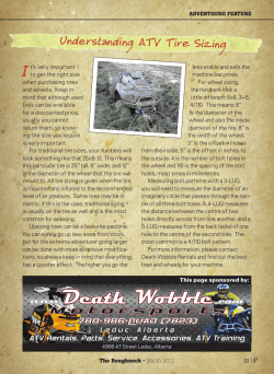


© Copyright 2026