
Chapter 16 to Implement Component How
Chapter 16
How to Implement
a Component
To implement a component means to devise a partition into smaller components and to
define (a) the behavior of each one as a type and (b) the interaction between the smaller
components that realizes the originally specified behavior.
There are many considerations to partitioning the components, with trade-offs on flexibility, reuse, and performance. This chapter discusses these trade-offs and provides a set of
patterns for making these decisions.
To claim that we have implemented a specification, we must also document how the
design meets the spec: Retrieve the specified model from the design and map design
action sequences to abstract action specs. This chapter also outlines how to document this
refinement.
16.1 Designing to Meet a Specification
The Catalysis refinement techniques make it possible to layer the design process so that
the decisions that have the most far-reaching effects are clarified and are taken before the
more trivial ones. A significant boundary in this layering lies between specifications of
behavior (characterized by types) and descriptions of how that behavior is achieved (characterized by collaborations).
This chapter is about how you design a component to conform to a given type (behavioral spec). Again, it might be a complete suite of software, a component part of such a
system, or a small object within the software. Or perhaps it is a mechanical system or
human organization that you have decided to design using object-oriented methods (in
which case, let us know how you get on!).
The spec might also be only a partial one: the view seen by an external actor through a
particular interface.
639
640
PART V
HOW TO APPLY CATALYSIS
The principal objectives to be met are as follows.
• Conform to the spec; we have this in common with all methods of software design.
• Build from well-decoupled components; this is a particular strength of object-oriented
design.
• Retain precise traceability from spec to code; this is a speciality of the more serious
development methods.
• Balance all the preceding within a design process that takes account of different development circumstances; this can be achieved with Catalysis.1
Decoupling tends to introduce much more separation between concepts than is typically found in an analysis. For example, any aspect of an object’s behavior that could conceivably be varied tends to get delegated to a separate plug-in module. Thus, we end up
with many more types of objects than were mentioned in the specification. Nevertheless,
our refinement techniques (see Chapter 6, Abstraction, Refinement, and Testing) enable us
to keep the traceability between the two models.
1. If you want us to write your advertising copy for you, we are very affordable.
Chapter 16
How to Implement a Component
641
Pattern 16.1 Decoupling
This pattern reduces the dependencies between parts of the design to make them able to
function in many configurations.
Intent
This pattern is useful in creating a design of any kind, in which dependencies between
parts must be reduced.
Considerations
Decoupling means minimizing the dependencies between the different pieces of a design.
The more coupled a piece is to others, the less easy it is to reuse in a different context
because it would have to be redesigned to work with its new neighbors. Creating any
design from decoupled parts means that we can design new ones more rapidly, because we
don’t have to start from scratch. The designers of a new lamp, printer, phone, kitchen, or
car does not begin by considering a lump of raw metal.
Work of Generalization. Reuse extends from simply calling the same routine from different parts of a program to publishing a design on the Internet. Whatever the scope, some
work is necessary to generalize the design, as we discussed in Section 11.1.4, A Reuse
Culture.
Importance of Interfaces. At one time, modularity in the software world was principally
motivated by the need to divide a big job into manageable tasks. The interfaces of your
module worked with the modules of the people in the neighboring cubicles; it was easy to
discuss any issues about the interfaces. In a culture that reuses the pieces, you are unlikely
to know all the components that yours will connect to: You must therefore be much more
careful about your interface definitions (and about reading those of others).
Strategy
Coupling is introduced when one piece of a design mentions another by name: another
class, another procedure or method, a variable in another class, or even (heaven forfend) a
global variable. Explicit mentions of other classes may come in parameter or variable declarations; in type casts; when objects are created explictly of a particular class; and when
one class inherits from another.
Therefore, you should avoid accessing variables outside your own class; always go
through access methods instead and try to provide higher-level services instead of only
get_ and set_ methods.
Separate concerns into different objects (and abstract objects; see Section 6.6, Spreadsheet: Object Refinement). Compose those objects together to provide the overall behavior. In general, prefer composition and black-box reuse over subclassing.
642
PART V
HOW TO APPLY CATALYSIS
Minimize the number of explicit mentions of other classes. Refer to other objects by
their types or interfaces. When you need to instantiate another object, use a factory
method rather than directly name the class to instantiate.
Minimize interfaces—that is, reduce the number of methods within each class that are
used by another.
Draw dependency diagrams (see Section 7.4, Decoupling with Packages) between
operations, classes, packages, and components. Study the package-level dependencies and
seek ways to refactor across packages to reduce coupling.
Chapter 16
How to Implement a Component
643
Pattern 16.2 High-Level Component Design
In this pattern, you design large-grained components and connections.
Intent
Define component boundaries; you have a type specification of a system that you are to
design.
Considerations
Object-oriented design is about decoupling; the major aspects of the way a component
functions and connects to its neighbors can be separated into different subcomponents.
Strategy
Identify each major interface to the world outside the component: user interface, hardware
monitor or drivers, and links to other components. This process provides a horizontal layering of the component.
Consider whether a façade is required for each of these interfaces (see Section 6.6.4,
Object Access: Conformance, Façades, and Adapters, and Pattern 16.4, Separating
Façades). Each façade is a subcomponent in its own right. If the interface is to another
component within the same piece of software, the answer may be no: The interaction is
direct. If the interface is to a person, the façade is a UI of some kind.
Reify the major continuous use cases (see Section 6.5.7.1, Reifying Actions, and Pattern 16.3, Reifying Major Concurrent Use Cases) that the system supports—often corresponding to business departments—such as loan books and manage stock. Each of these
use cases can become a component that itself can be further reified. This approach provides a vertical partitioning of the component.
In deciding the functions of each major component, consider what can be most easily
implemented with existing components or frameworks.
Consider whether the components should be in separate machines or separate languages. (See Pattern 16.5, Platform Independence.)
Choose the infrastructure components that will constitute your technical architecture
(see Pattern 16.7, Implement Technical Architecture).
Use Pattern 16.8, Basic Design, to sketch interactions between subcomponents. While
drafting a basic design, also apply appropriate design patterns (see Section 16.2, Detailed
Design Patterns) to improve decoupling.
Specify each major component, particularly the core business components. Recurse
this procedure on each subcomponent until the interacting subcomponents are simple
classes.
644
PART V
HOW TO APPLY CATALYSIS
Pattern 16.3 Reifying Major Concurrent Use Cases
This pattern describes recursive use-case-driven design.
Intent
The aim is to divide a large component into its major functional blocks, by use case.
Strategy
A business can be considered to comprise several large-scale use cases, each of which can
be supported or run by a computer system. Frequently, the importance of the major use
cases has already been identified, and they have been reified as business departments.
Usually, these functions operate continuously and are interconnected in some way (see
Figure 16.1).
The major use cases can now be reified to become objects that support those use cases.
In this case, the use cases are complex, so the corresponding objects will be large enough
to be refined separately. They might be set up in different computer systems. We can also
show the actions whereby the objects interact with each other (see Figure 16.2).
Each of these objects should now be designed as a component in its own right, preferably starting with a specification. Each object will have its own model of what a book is
run library
Member
Library Employee
lending books
managing stock
Loan statistics
stock available
Member
StockKeeper
Desk Clerk
Figure 16.1
Concurrent business functions (use cases) interact.
(see Section 10.11, Heterogenous Components). Each of them has one façade to a human
user and another façade to the other component.
Chapter 16
645
How to Implement a Component
These components could be distributed among various host machines.
Library Management System
loan stats update
Book Loan Support
Stock Management Support
book stock update
lending books
Member
Desk Clerk
managing stock
StockKeeper
Figure 16.2 Reified use cases into large-grained objects.
646
PART V
HOW TO APPLY CATALYSIS
Pattern 16.4 Separating Façades
Separate the GUI (and other layers that interface externally) from the core business logic.
Intent
The objective is to achieve horizontal layering, separating business from technology components.
Considerations
One principle of OO design is that you mirror the business types in the software. But in addition to the business functions, there are practical things to be dealt with, such as the presentation of pictures on the screen or the interpretation of mouse clicks or of signals from other
machines. It’s possible for a naïve designer (or a mediocre visual interface-building tool) to
get the user interface well mixed with the business logic; but it is not recommended. We may
wish to change the GUI without changing the business, so it is preferable to have everything
separate.
The GUI involves more than one class—usually several classes for every kind of shape
and display and every displayed business object. So we are talking here about another substantial component. Considerations that apply to the user interface also apply to interfaces
to other external objects, so an interface to a separate component would also use a façade.
Once these façades have been separated out, we are left with a core component in the middle that reflects the business types and represents the business logic in its code.
Strategy
Take each of the major components identified from major use cases—in a simple system,
there may be only one—and separate out subcomponents, each of which is concerned with
an interface to an external object (user, hardware, other software). Figure 16.3 shows an
example.
Notice that each component could be broken down further if required. This is object
refinement (as described in Section 6.6, Spreadsheet: Object Refinement).
Each component could be in a separate machine if required (as in client-server and the
Web).
Each of the components has its own model of objects it is interested in. They include
static types and reified actions (use cases). Examples are an object controlling the interaction with a user or, in the business logic, a long-term action such as loan.
Façades as Transparent Media. The need for a façade is largely to provide a way for
messages to be sent across system boundaries. For example, we can define a message in
Chapter 16
647
How to Implement a Component
Book Loan Support
Graphical User Interface
for Member inquiries
Graphical User Interface
for Desk clerks
Display of Book for Member
Display of Book for Clerk
Inquiry transaction manager
Reified desk action
Interface components
contain objects about
communications
Interface to Stock
Management Support
GUI components
contain objects
about presentation
and small use cases
Core components
mirror business
types
Book Loan Core
Reservation
Member
Loan
Book Title
Book Copy
Missive about
Books
Reified action
about stock control
Figure 16.3 Possible façades.
the book loan core called reserve(title, member) in which each of the parameters is a
pointer to an object of the appropriate type.
Now consider how that gets invoked. If the invoker is another piece of software in the
same platform, the procedure call mechanism deals with the message send; memory
addresses represent the object references. But if the invoker resides on another machine,
some kind of remote method invocation must be employed; instead of memory addresses,
some other kind of identifier must be used for the objects.
The situation is even worse when the invoker is a person. There is no one-shot way for
a user to invoke a subroutine with multiple parameters: You must go through some interaction that gathers the information one piece at a time. This is half of what the GUI is for;
the other part is the presentation of the states of core objects, something that is also a job
of translation.
At the other end of the communications medium—be it a wire or screen + eyeballs +
keyboard + fingers—there is another façade doing the translation in the opposite direction.
In this way, the cores of the two components communicate2 (see Figure 16.4).
Façades between Components in the Same Platform. Sometimes there is no need for a
façade: The two components send messages and keep pointers directly to each other.
Because each component may be an abstract object (see Section 6.1.7, Object Abstrac-
2. This idea is similar to that of the OSI protocol stacks used in communications.
648
PART V
Core1
Effective interaction
Façade1
Figure 16.4
HOW TO APPLY CATALYSIS
Core2
Façade2
Layered communication via façades.
tion), it may be that there is no single memory address representing each component: The
two have numerous pointers directly between their consitutent objects.
Chapter 16
How to Implement a Component
649
Pattern 16.5 Platform Independence
Localize, in one component, ideas that are dependent on a particular platform.
Context
By “platform,” we mean the technology that underlies the execution of your design. Here
are examples:
• Programming language, operating system, runtime environment: Java, C++, Windows,
UNIX, Smalltalk, Forté, Javascript on Netscape, workflow systems, and so on
• Persistence: How the state of the component is preserved for any length of time (file
systems, databases)
• Distribution mechanisms: COM, CORBA, RMI, TCP/IP, and other technology (but
consider which component is run on which machine)
All these infrastructure questions can be separated from the main issues of design. Outside their own layers, they should not make much difference to the design.
Strategy
Adopt techniques that keep as much of your design and code as possible independent of
these layers.
This means that you should design using an insulating layer or virtual machine of
objects in which the differences between one platform and another are concentrated. In
this way, porting means changing only that layer. Also, keep the design well documented.
Although porting would mean rewriting the code, it could be done quickly from the existing design.
Examples
The Java language provides a virtual machine that runs the same on all hardware.3 The
public GUI classes in the Java library are the same for all hardware, but they are façades
for a layer of peer classes that adapt to the local operating system.
3. Never quite true, though, eh?
650
PART V
HOW TO APPLY CATALYSIS
Pattern 16.6 Separate Middleware from Business
Components
The point of this pattern is to separate business components from others. Wrap legacy systems behind a layer of objects representing the business concepts. Transition from custom
infrastructure solutions to standardized middleware, enabling integration and extension of
disparate systems in a way that is shielded from technology changes.
Encapsulate persistence mechanisms in a small number of platform-dependent objects
with platform-independent interfaces. Separate out technology-dependent infrastructure
components that serve primarily to connect other components, such as message queues,
transaction servers, ORBs, and databases.
Intent
The objective is to build new business components that can integrate with legacy systems
and across disparate systems while shielding the system from technology changes.
Considerations
The legacy system might be only a file server or a relational database. Or it might be a
higher-level component, such as a spreadsheet with an API, or a complete application such
as a reservations manager.
It may be “legacy” in the sense that there is a lot of code and data already built for a
given application or only in the sense that compatibility constraints force the use of moretraditional technology such as RDBs.
Integration of disparate systems involves a lot of infrastructure support: communication, coordinating distributed transactions, load distribution, and shared resource management. The costs of developing infrastructure components of high quality would dominate
a typical large business project compared with that of the actual business logic involved.
Strategy
Make a layer of business objects. In a client-server system, they typically reside on the
server (although this strategy is independent of their location). The business objects correspond closely to the types found in the business model and deal with users’ concepts,
roles, departments, and so on (see Figure 16.5). As the business changes, it is this layer
that is updated.
The GUI is a separate layer. In contrast to an older client-server (two-layer) architecture, the user interface should deal only with presenting business objects to users and
translating user typing, mouse clicks, and so on to business object commands. Business
rules should be embodied within the business objects.
The underpinning or old technology of database, communications, and so on is represented by a set of wrapping objects that drive them.
Chapter 16
651
How to Implement a Component
Business model
Middleware
Object
wrapper
Object
wrapper
Client interface
Business component
can track business
model more easily
Non-object
technology
Non-object
technology
Legacy systems
Figure 16.5 Middleware and business components.
A variety of techniques exist for driving legacy components. You can use the API if
you’re fortunate enough to have one, or you can generate and send SQL or similar queries
if it is a database component. For a host-based terminal application, you can use screenscraping—pretend to be an old-style user terminal. These techniques should be encapsulated in middleware so that other components are not too dependent on the legacy communication. Whenever possible, buy the middleware components.
To use such a component accurately, it is helpful to build a model of it.
Benefits
The first benefit is platform independence. The business objects can be written independently of the legacy systems and can be ported. Using middleware, you can integrate new
application components with existing application code and purchase components to build
seamless business systems.
In addition, the software tracks business reorganizations. As usual in OT, the strength
of reflecting the business organization in the software is that it can readily be rearranged
when the business is reorganized.
Software location also tracks business location. Distribution of the objects among hosts
comes after and is independent of object design (see Pattern 16.12, Object Locality and
Link Implementation). This applies whether there is a central server or several servers or
whether the business objects are hosted on server machines or clients or in their own
machines. The strength of this independence is that the hosting can easily be rearranged—
dynamically, if appropriate—as people and departments are relocated.
652
PART V
HOW TO APPLY CATALYSIS
Pattern 16.7 Implement Technical Architecture
In this pattern, you document the selection of all infrastructure components and describe
how they relate to the physical and logical architecture to be used. Implement the supporting pieces as early as possible and build an early end-to-end architectural prototype.
Intent
Reduce feasability and scalability risks of technical architecture.
Considerations
Much of the complexity and development cost of a large system can come from issues
related less to the business logic than to technology factors: database access, general querying capabilities, message passing paradigms, exception signaling, interpreters for command
languages, logging facilities, a framework for startup and shutdown, user-interface frameworks, and so on. These factors can be the most important ones in reasonable estimation of
design and development times.
Coherence and maintainability of the system degrade rapidly if different developers
choose their own schemes to solve these technology issues. Large-scale performance and
scalability are determined primarily by how the components are partitioned and distributed across machines and by the nature of communication across machines.
Strategy
Make the design, implementation, and rules for using any infrastructure components a
high priority. Separate distinct technology pieces.
• Presentation: Select a standard mechanism for all user-interface presentation—for
example, MVC or document-view—and an implementation to go with it.
• Business: This category covers application components that partition application logic
and business rules and collaborate to achieve the required business function.
• Middleware: This is the communication and coordination mechanism to enable components to collaborate across machine boundaries.
• Component technology: This includes the kinds of components and connectors that
define more-expressive modeling and design constructs such as events, properties,
workflow transfers, and replication.
• Data storage and access: This is the database access layer along with a logical layer
above it to coordinate shared access to the data.
• Utility classes: Design and implement other domain-independent services, such as querying, exception signaling, message logging, command interpreters, and so on.
Use package diagrams to show the third-party and library components you will use. If
you use a layered architecture, in which higher layers can call only layers below them, you
Chapter 16
How to Implement a Component
653
can visually structure these diagrams to show the static dependencies corresponding to
architecture layers. Explicitly capture tool dependencies (language versions, compilers, UI
builders) across lower-level packages, introducing virtual packages for these tools if
needed.
Use collaborations to show interactions between large-grained components and stereotypes or frameworks on the interactions (for example, «SQL», «RMI»).
Document in a package the overall guidelines or cookbook rules, including design and
coding standards, that you want to follow for all these issues and particularly the rules to
follow when adding new features to the system.
654
PART V
HOW TO APPLY CATALYSIS
Pattern 16.8 Basic Design
Take each system action and distribute responsibilities between collaborating internal
components. Begin by assuming that there is a class for every type of the system type
spec.
Intent
The aim is to generate classes for coding based directly on specification types.
Context
A component specification has been written. It may come from requirements analysis (see
Pattern 15.7, Construct a System Behavior Spec) or may be a part of the design of something
larger (see Pattern 16.3, Reifying Major Concurrent Use Cases).
The component has been characterized with a type, specifying the actions it can take
part in, in terms of the vocabulary of a static model. Figure 16.6 shows an example. These
actions can later be refined to more-detailed interactions.
Considerations
Basic design is the first attack on a design before any consideration of optimization (see
Pattern 16.13, Optimization) or generalization (see Pattern 16.11, Link and Attribute
Ownership).
Classes, Specification Types, and Design Types. The types in a component’s model are
often called specification types because their reason for existence is to help specify the
component’s actions. A designer could invent a completely different internal structure that
would still conform to the specified behavior as seen by external clients—a decision that
would be justified by performance or other constraints.
Library Management System
Reservation
1
Member
1
1
*
*
*
Loan
Book Title
1
0,1
1
*
Book Copy
action return (book : Copy) pre: book.loan <> null
post: book.loan=nil and [[holdForReservation(book)]]
action borrow (book : Copy, member) pre: . . .
Figure 16.6 Type specification to be designed.
Chapter 16
How to Implement a Component
655
When you do a design, you define collaborations that divide responsibility among different types. These are often called design types, meaning that we know we must implement them at some stage; we indicate this by drawing them with slightly thicker boxes. In
fact, the difference between specification types and design types is not intrinsic nor hugely
important but reflects only the way you use them. You could just as easily use a design
type—that is, one that you happen to possess an implementation of—as part of someone
else’s model.
The distinction between class and type also boils down to how you use it. After some
quantity of refinement and design, you will end up with a type diagram in which all the
actions are localized (that is, there are arrows showing which end is sending and which
receiving), all the associations are directed (arrows showing who knows about whom),
and all the actions have interaction schemes. At that stage, it is natural and easy to translate it all systematically into your favorite programming language. Nevertheless, you
could stoutly maintain that it’s all only a model. But generally, when we draw a box with
directed links and localized actions that have interaction schemes, we’ll refer to it as a
class rather than a type.
Encapsulation. According to the principle of encapsulation, the internal structure of
each unit should be invisible to others. In that way, each unit is designed to depend
only on the behavior of those to which it is coupled. So what’s a unit?
Class 1
The class (or the object) is conventionally taken to be the
unit of encapsulation. But this isn’t invariably the optimal
solution: It may be useful to have a variable assortment of
state-holding objects within a single design. If there is no
intention ever to separate the design and if the pieces
couldn’t possibly make sense apart and will never be modified one without the others, then the unit of encapsulation is
sensibly bigger than the object. It makes more sense to
make the unit of design the unit of encapsulation (something that Java acknowledges by permitting visibility
between classes in the same package).
Type 2
action x
Type3
Interaction
scheme
for action x
specified
actions
Ideally encapsulated design:
one class uses several types
and each class implements
many types
Class
Class
Type
Class
Easier but
less flexible
deep design
Type
Type
Class
In any case, it can be difficult to begin a new design
by working immediately with abstract types. It is easier
to design the drawing editor beginning with example
shapes and then generalize, carefully specifying in the
Shape type what you require of any new shapes. Similarly, it’s easier to design a library with books in mind
and then generalize to videos and car rental. Brains
work bottom-up.
656
PART V
We have found that it works well to
begin with a large unit of encapsulation
spanning several classes and then gradually
draw the boundaries in. So we typically
design sequences of operations that trace
the flow of control several levels deep
through the object graph. Generalizing is a
subsequent step, which is done by defining
a type for each class and then making it as
general as possible. These then become
cross-package interface specs.
Class
HOW TO APPLY CATALYSIS
Type
Type
Class
Type
Type
Type
Class
Type
Type
Class
Type
Strategy
Assign each system-level action to an internal object. In another part of the development
(see Pattern 16.4, Separating Façades), the task of interfacing our component to its neighbors was delegated to a subcomponent. We can make some assumptions about how we
will design the façade.
• Presentation of the state of the core to the external world will be handled appropriately
by the façade. It will use observers (see Pattern 16.17, Observer) so that we need not
consider the detail about how things appear on the screen. All we need do is keep the
business objects’ own state right.
• To the core the façade will send messages corresponding to the main actions we identified for the component as a whole.
• Each message will initially arrive at the most appropriate object in the core, which will
then delegate some of the work to others. This object is called the control object for that
component-level action.
The library is typical of many designs in that each type of external user talks to its
internal proxy: each (real) ::Librarian through an instance of LibrarySystem::Librarian, each
::StockKeeper through an instance of LibrarySystem::StockKeeper, and so on (see Figure
16.7). Logging in establishes these connections via the screen, keyboard, and windows
(each of these pieces of hardware has its software counterpart).
Real counterpart of —— internal proxy
: GUI
Internal proxy of —— real object
: Business Core
jo:Librarian
: Façade
to robot
:Robot
Jo
observe
Figure 16.7 Consistent use of proxies.
:Robot
Chapter 16
657
How to Implement a Component
Program each system-level action. For each action specified for the component as a
whole, design how its spec will be fulfilled by a collaboration of objects within the component. Make the starting assumption that the classes and pointers available are the types
and associations from the component spec’s static model.
To design each action, draw a before-and-after snapshot of a typical component state
for this operation. Do them on the same drawing, with the after links distinguished, for
example, by color. Work from the action spec: Ensure that your before situation satisfies
the precondition.
held
3.1.1.1. equal(t)
: Book
Chris : Member
3.1.1. title(t)
t: Title
3.1. need?(t) → m
3.2. holdFor(m)
reserved
3. available
1.
return
4
: Book
2
Pat : Member
held
loaned
Jo : Member
1. Book informed that it is returned
2. Book removes loan link to Member
3. Book informs title that it is available
3.1 Title asks each reserving member if it needs the book
3.1.1 Member checks books already held for same title
3.1.1.1 Book checks if same title
3.2 Title tells book to hold for particular member
4. Book sets up the held link for that member
Figure 16.8
Interaction design.
Work out which operations each object must invoke on its neighbors, beginning with
the head object, to achieve the after situation. To stick to basic design, your messages
should only follow links. Draw them on top of the snapshot. It usually helps to number
them in sequence of occurrence. Also number creations and deletions (see Figure 16.8).
The benefits of encapsulation become clear in this example. Do we really want to chase
all the way down 5 and 6 to see how a book knows its title in this piece of design? See Pattern 16.9, Generalize after Basic Design.
Write stub operation specs wherever the interactions become too deep. For example,
you can write a spec for Title::available (b: Book) and omit all details below 3 in this interaction diagram.
Title::available (b: Book)
post
book put on hold for one member with needy reservation for title
(needy reservation for title = reservation for title, with no held copy)
658
PART V
HOW TO APPLY CATALYSIS
If there are any different cases described in the postconditions not dealt with by the
sample situation you have illustrated in the snapshot, repeat for the other cases. (With
experience, of course, you can often skip all the tedious drawing. However, it’s good to do
some.)
It may be useful to redraw the design as an action sequence diagram (see Section 4.7.3,
Sequence Diagrams with Actions). This technique shows the sequence more tidily and
makes it easier to see how to move responsibilities “sideways” from one object to another.
The role-activity variation also shows potential interference clearly (when one object is concurrently engaged in several threads).
When you’re programming, follow the principles of coherence (see Pattern 16.10, Collaborations and Responsibilities): assign responsibility where it is appropriate.
Review Responsibilities and Collaborations for Each Class. After you program each
system-level operation, each of the classes on which operations are invoked has a list of
operations it is required to do. Document these operations as detailed in Pattern 16.10,
Collaborations and Responsibilities, and review.
Consider Ownership of Each Link. That is, who knows about it? See Pattern 16.11,
Link and Attribute Ownership.
Decide Distribution. That is, where does each object reside? On which machine? On what
storage medium? In which major component? This can be done independently of the design.
See Pattern 16.12, Object Locality and Link Implementation.
Decide How Objects, Links, and Actions Are Implemented. This is highly dependent on the answers to the preceding question. Each component may have its own internal
representation of objects: as C structures, as Java or C++ objects, or as files or database
records. Links may be memory addresses, URLs, CORBA identifiers, database keys, or
customer reference numbers, or they may be refined to further objects. Actions may be
further refined and ultimately be function calls, Ada rendezvous, signals, or Internet messages.
The implementation of links typically induces further message sends. For example, setting up or taking down a two-way link requires a housekeeping message (see Pattern
16.14, Two-Way Link).
The head class of the design is one possible implementation of the type represented by
the system spec. The implementation class should have a separate name. If there is likely
to be only one implementation, a reasonable convention (following [Cook94]) is to call
the type ILibrary and the class CLibrary, for interface and class. The refinement relationship
should be documented in the dictionary. (In Java, class CLibrary implements ILibrary.)
Collate Responsibilities of Each Class. The actions in which each class takes part can
now be listed. Each one can be specified (if only informally).
Chapter 16
How to Implement a Component
659
Generalize. Push encapsulation toward each class being independent of all the others.
Each action diagram should go only one level: the actions used by any method should
depend only on the specifications of others.
It doesn’t make much sense to encapsulate certain classes separately: you know that
they will always go together. For example, how a current user selection is represented
depends heavily on the design of the document. So, for example, the TextDocument and
TextSelection classes will generally form part of one package and can be coded in a single
Java package, C++ file, and so on.
On the other hand, an Editor may be able to handle many kinds of Document, so it
makes sense to define a Document design type, with all the behavior the Editor expects,
and provide several implementations. Defined fully, Document would have a complete
model and operation list just as Editor does.
Reiterate for Each Design Type. The design has now been decomposed, and each
design type can be implemented by designing it or finding a suitable library component.
Coding. Translate the classes and associations into program code.
Benefit
The benefit is that the system is designed to a spec. You can start easy, generalize, and
optimize locally later.
660
PART V
HOW TO APPLY CATALYSIS
Pattern 16.9 Generalize after Basic Design
Work with particular cases first and then generalize using decoupling patterns.
Intent
The aim is to achieve good decoupling by re-factoring an initial design.
Context
A draft design has been achieved using Pattern 16.8, Basic Design.
Considerations
There is a tendency for the design to be poorly decoupled after you do basic design. That
pattern works with an overall view, using sequence charts and snapshots to show how
messages propagate through the various layers of objects. But that very advantage works
against encapsulation and decoupling: You are designing each object in a context in which
the other classes are known, and the tendency is to make it work with those specific neighbors.
That does not mean we should throw out basic design or the notational tools that help
it, although that has been suggested in some respectable quarters. We believe that human
brains work best with concrete examples and that you cannot design a generalization without first creating something concrete.
Strategy
Apply generalizations after you complete the basic design. A wide variety of design patterns are directed at generalization and decoupling. Most notable are Pattern 16.15, Role
Decoupling and Pattern 16.16, Factories.
In the library example, we can begin by lending books and then diversify into videos.
Then we can privatize the library and start charging money.
Chapter 16
661
How to Implement a Component
Pattern 16.10
Collaborations and Responsibilities
In this pattern, you document and minimize responsibilities and collaborators.
Intent
The intent is to distribute responsibilities among objects in such a way as to produce a
flexible, coherent design.
Context
The context is action refinement: making decisions that implement or put more detail into
an abstract (set of) actions. This may be part of a computer system design (Pattern 16.8,
Basic Design) or part of the reengineering of a business process (Pattern 14.1, Business
Process Improvement) and may in particular be the engineering of the business process of
which using a computer system is a part (Pattern 15.5, Make a Context Model with Use
Cases).
A collaboration diagram defines interactions between objects. A collaboration is a set
of actions that are related in some way, usually a common goal. Here are some examples.
• The maintenance of an invariant
Counter
update
value
CounterDisplay
getValue
shows
inv Counterdisplay :: shows=myCount.value
• Forming a refinement of a more abstract action (involving [some subset of] the same
participants)
Customer
Customer-R1
buy_food
Café
select_food
pay
Café-R1
• Forming the implementation of an action (in which one object employs the services of
others to fulfill its responsibilities to someone else)
User
Editor
cut
Editor-I
cut
remove
Document
replace
The dictionary details the responsibilities of each type or class.
ClipBoard
662
PART V
HOW TO APPLY CATALYSIS
Considerations
Each participant in the collaboration should have a responsibility that can be succinctly
stated: “displays integer values” or “sells food” or “represents recently deleted items in an
editor.” The actions should be a small set all of which relate directly to this responsibility.
The more specialized the collaborators of an object—the further down the type hierarchy—the less generally its design can be applied and used. The objective is to make the set
of objects with which it will work as wide as possible.
Classes, Types, Design Types, Abstract Classes. The collections of methods for the
actions now form classes. The boxes to which you sent messages without programming
them further are design types: You know what you want them to do but haven’t yet
decided how. The process can be repeated for them later.
Strategy
Document Responsibilities and Collaborators. Record the following in the dictionary:
•
•
•
•
The responsibility statement for each class or type
The collated list of actions and collaborators for each class or type
The specifications of each action
The refinement of each action (for example, as skeleton method code)
Localize Actions. A general joint action
Customer
Shop
represents an interaction between the participant types without
saying who does what. But at this stage, neither of the particibuy
pants can be understood independently of the other. LocalizItem
ing the action doesn’t by itself reduce this coupling but is a
useful preliminary to generalizing
the sender end (see next point). Decide who is the sender and who the receiver. Mark them
with arrowheads. Any other participants remain as parameters. (Writing the name and signature of the action within the behavior section of the receiver’s type box is also a way of
indicating localization.)
Minimize Coupling (Dependencies). The list of collaborations should be small. The
well-known CRC technique of detailing responsibilities and collaborations on a single
index card gives some idea of their preferred sizes. If the list is too large, suspect that a
redistribution of responsibilities is required.
For each type, consider whether it is possible for its collaborators to have more-general
types. For example, an Editor might work with Documents of any type (such as Texts)
rather than only Drawings; conversely, a Document need not be driven by an Editor.
Redraw using the more-general types.
Chapter 16
Person
How to Implement a Component
0..1
Fruit
eat
0..1
663
If you wish to focus on one participant type for the
present, you can indicate that this is not the whole range of
possibilities by using an “optional” mark.
In the most extreme case of decoupling, the receiver doesn’t care at all what type the
sender possesses, because the receiver never sends any messages back to the sender. This
implies that the action we’re looking at is never going to be refined further, and it is at this
stage that we usually start calling it an operation or message or function call and expect it
to be coded directly in the program. The sender’s type is then Object, the type of which all
others are subtypes.
Actually, this is not quite true. Even at the message level, there is some dialog, that
depends on the sender’s understanding what it gets back. An operation coded to be
invoked as a function call needs a different sender than one invoked through an ORB or a
dynamic linking system. Asynchronous and synchronous calls are different again. So
strictly speaking, you must always know something about who is calling you, at least to
the extent that you impose some requirements on its proper behavior.
For each type, consider whether the number of its collaborators can be reduced by a
rearrangement of responsibilities. For example, we get the Editor to transfer deleted material to the Clipboard rather than get the Documents to talk to the Clipboard at the Editor ’s
behest. That avoids the need for the Document (or its designer) to know about Clipboards,
with the benefit that Documents can be reused in other designs where there is no Clipboard.
Consider the many other forms of decoupling listed in design pattern texts. The decoupling results in designs that are easier to pull apart, using the parts as components in different contexts. Decoupled designs also are more resilient to change; each interface impedes
the propagation of change.
664
Pattern 16.11
PART V
HOW TO APPLY CATALYSIS
Link and Attribute Ownership
The aim here is to decide and document the directionality of links.
Context
The context is late-stage design. You have worked out the collaborations (see Pattern
16.10, Collaborations and Responsibilities).
Considerations
A link (or attribute) in an abstract spec or design represents the fact that somewhere,
somehow, there is a member of one type associated with every member of the other type.
The link says nothing about how the types are associated.
There are various possibilities. The most straightforward are as follows.
• Each type knows about the other (see Pattern 6.4, Refinement Is a Relation and Not a
Sequence), something that is frequently represented using a two-way link. Although
simple, this link often results in excessive coupling. A simple measure would be to
decouple using types (see Section 7.4.1, Role-based Decoupling of Classes).
• One type knows about the other, but not vice versa. This is usually the preferred solution: It layers the dependencies and makes testing simpler.
• Neither type knows about the other, but a third object keeps a mapping between them.
When used systematically, this approach can be used to make objects appear more
extensible: Its basic implementation is already defined, but an external mapping helps
define extensions to its properties and behaviors.
• No one stores the information directly, but it can be computed.
A link is needed in a particular direction if an object must retain a reference to another
across its public methods—for example, it must send a message down that link—or must
keep the identity of an object for someone else—for example, as a list does.
Strategy
Notice that this issue is separate from link implementation, which has to do with Pattern
16.12, Object Locality and Link Implementation.
Chapter 16
How to Implement a Component
Pattern 16.12
665
Object Locality and Link Implementation
Locality of an object can be decided independently of basic design, employing appropriate
patterns to implement links and messages crossing locality boundaries. Locality applies to
hosts, applications, and media.
Intent
Decide where an object will reside and whether and how it will move around.
Context
This work is done after object design (see Pattern 16.8, Basic Design) and link ownership
(see Pattern 16.11, Link and Attribute Ownership).
Considerations
Essentially, these issues are all the same, or very closely related.
• Which host an object resides on in a distributed system
• Which storage medium and platform an object is in (database, serialized in file, main
memory, on a listing, in a bar code, on a magnetic stripe card, and so on)
• Which application or major component an object is in (in a spreadsheet or word processor; in a banking application; in a tax authority program)
In each case, we must worry about the following questions.
• How is the object represented in that locality? Can it execute there?
• Does the object move across locality boundaries (for processing or storage or to be processed locally for efficiency)? What makes this happen?
• If it crosses boundaries, are there then two copies (for economy or robustness)?
• If there are copies in different localities (temporarily or permanently), how are they
kept in sync (paging or transaction tactics)?
• What are the performance implications of this distribution?
• How are cross-boundary links represented (URLs? keys? reference numbers?)?
• How do actions between objects in different localities work? How are parameters represented in transit?
• How should we handle different views and capabilities in different localities (for example, a picture in a CAD program imported into a word processor)?
• The basic object design should be independent of locality and boundaries and movements. How is this made to work?
666
PART V
HOW TO APPLY CATALYSIS
Strategy
Use standard frameworks for distribution, including CORBA, Active-X, and COM+.
Because these decisions can be taken late, the basic design is changed very little by distribution across localities in a functional sense. This means that a distributed system can
first be implemented on a single machine as a prototype. However, the performance implications can be significant, so, depending on the amount of interaction with the object and
the bandwidth of the communication medium between them, architectural prototypes
should be built early to validate both locality and responsibility decisions.
Chapter 16
How to Implement a Component
Pattern 16.13
667
Optimization
Apply localized refinements to make the application run faster.
Intent
The objective is satisfactory performance.
Context
Optimization should be undertaken after object design (see Pattern 16.8, Basic Design)
and link ownership (see Pattern 16.11, Link and Attribute Ownership). Juggle with object
locality (see Pattern 16.12, Object Locality and Link Implementation).
Object-oriented programs typically run 25% slower than their traditional counterparts,
and they take up more space. And the more they are engineered for reuse, the slower they
run. The cause? It’s the dynamic name resolutions, and it’s all those message sends
between objects politely observing their demarcation rules, carefully deferring to the
responsible person for each part of the job like a bureaucracy gone mad. (Is this an argument against applying the OO paradigm to business processes?)
Considerations
See Pattern 6.2, The Golden Rule versus Other Optimizations—optimization balances
against flexibility.
Strategy
Eighty percent of the time is spent on 20% of the code. The majority of the code can mirror the business model: After running profiling tools to ascertain performance bottlenecks,
concentrate on the worst 10% of the 20%.
Initial optimization should usually be focused on the levels of algorithmic improvements while trying to retain encapsulation. Beyond that, optimization is largely a matter of
specialization and coupling—making one piece of code more dependent on its neighbors—and of technology-level optimization—improving locality and paging behavior,
reducing network traffic, and tuning the database structures.
•
•
•
•
Direct access to data; use friends (C++) or in-package access (Java)
Less delegation; bring more of the job within one object
Use static data structures
Make standard optimizations as for conventional code
Object locality (see Pattern 16.12) is also an issue. Various patterns, such as caching
and proxies, can be used to bring an object closer to the point of application while minimizing overhead and impact on the design.
668
PART V
HOW TO APPLY CATALYSIS
Benefit
A basic design built directly from the business model can very quickly be constructed and
run as a prototype, feeding back to the requirements analysis process. Optimizations can
be kept as a separate task.
16.2 Detailed Design Patterns
There is a rapidly growing literature on design patterns. Patterns enable designers to discuss their designs clearly with their colleagues and to convey sophisticated ideas rapidly.
Chapter 16
How to Implement a Component
669
We believe that all programmers should have a basic vocabulary of design patterns, and
we consider it inexcusable for a college now to release a computer graduate into the world
without this knowledge.
This section highlights some essential patterns and shows how they serve the major
objectives of decoupling. References to more-detailed discussion on these patterns can be
found in the Bibliography.
670
PART V
Pattern 16.14
HOW TO APPLY CATALYSIS
Two-Way Link
In this pattern, you make the participants in a two-way link responsible for linking and
unlinking.
Intent
In the latter stages of design, it is decided to implement a single abstract association as a
pair of pointers:
list *
A
B
0,1 ~list
Various messages sent by other parties to A or B may cause instances of the association
to be created or destroyed, adding or removing B instances from an A instance’s list.
Objective
The aim is to ensure that the pointers are always reciprocal. Although the membership of
the list may change, every item on an A instance’s list must have a ~list pointer back to that
A instance.
(a:A:: a.list.~list=a) and (b : B:: b.~list.list->includes(b))
Strategy
When one end of the link wishes to alter the list, it must first inform the other. In general,
the message must include self so that the recipient knows who it is being linked to. We
therefore have two messages:
void B::makeLink(a: A);
void B::breakLink(a: A);
// pre (~list=null)
// pre (~list = a)
The same thing applies in the other direction if it is required that B should be able to
initiate a change.
These messages should be used only between the participants in this link and should
not be the same as any other messages (for example, the messages from outside that initially prompt the objects to set up the link). This approach gives better flexibility.
makeLink is often invoked as part of a constructor initializing a newly created object.
Either the destructor of each object must send breakLink to all its list members, or it must
be demonstrated in the design documents that the object will never be destroyed when
there are list members.
Chapter 16
How to Implement a Component
671
Variants
The links may be one-to-one or many-many. If the cardinality is multiple at A’s end, then
B::breakLink(a) has a precondition (~list includes a).
One end may “own” the other—that is, making and breaking the link coincides with
creating and destroying the object. In that case, the job of makeLink is performed by each
of the constructor functions, and the job of breakLink is performed by the destructor. If
ownership can be transferred, a separate transfer function should be used.
The links are not necessarily pointers in memory: They can be database keys, names, or
any other kind of handle.
672
Pattern 16.15
PART V
HOW TO APPLY CATALYSIS
Role Decoupling
Declare every variable and parameter with an abstract type written for that purpose.4
Intent
The intent is to decouple by minimizing the number of operations a client explicitly
requires.
Context
We have a draft of a basic design; we seek to improve and generalize it.
Considerations
Few of the objects you design need to use all the messages understood by those it collaborates with. To put it another way, most objects provide a variety of messages that can be
divided into separate interfaces; each interface is used by a different class of client. This
situation enables substantial generalization.
Strategy
Declare every parameter and variable to be an abstract class or interface that specifies only
the operations used by that variable, and no more. (A less extreme version is to permit
some sharing of interfaces between variables.)
To show this technique pictorially, for every directed association between classes, draw
the link instead to a type specification (in C++, a pure abstract class; in Java, an interface).
The original target of the link is a subclass (Java: implementor) of this specification. In
Figure 16.9 we have decided that a Book is loaned not to a Member but to a BookHolder, of
which Member is only one possible implementation.
(Concrete classes are outlined in bold, abstract types with light rules.) Each type represents a role that the instances play in relation to the source of the link. Now it is easy to
imagine BookHolders other than Members and to imagine LibraryUsers other than Members.
4. This principle is enforced in some programming languages, such as CLU.
Chapter 16
673
How to Implement a Component
Loan
Library
Library
Loan
*
1
*
Member
acceptLoan
endLoan
notifyHold
chargeFine
payFine
sendMail
*
1
*
«type»
LibraryUser
«type»
BookHolder
chargeFine
payFine
sendMail
acceptLoan
endLoan
notifyHold
Member
Display Shelf
Figure 16.9 Using types as roles to decouple.
Benefits
The design has been generalized.
The designers of the surrounding classes are less likely to spread into using messages
not intended for their use, so there is a tighter control on decoupling.
Variations
Fanatics may apply this pattern to every variable and parameter and hence every link on
the diagram—two, for two-way links. Each class is surrounded by a cloud of the interfaces
it requires and the interfaces it implements.
Notice that a collaboration framework (see Section 9.3, Collaboration Frameworks) is
a set of roles coupled by actions—a logical extension of this pattern.
674
PART V
Pattern 16.16
HOW TO APPLY CATALYSIS
Factories
The idea here is to use classes and methods whose speciality is knowing what class to
instantiate.
Intent
The goal is to reduce coupling caused by explicit mentions of other classes in instance creation.
Context
After we have rid every declaration of any explicit mention of a class, we find that there
are still one or two class names lurking in the code.
Considerations
Role decoupling allows a Loan to work with any BookHolder and any LoanableItem so that
new variations could be invented every week; we could end up loaning geysers to Martians and never have to change a line of code outside those classes. But somewhere the
objects must be created, and at that point you must stipulate a particular class and not just
a type.
Strategy
Avoid distributing object creations all over the program. Instead, centralize the job of creating objects within factories [Gamma94]. The object-creation service provided by a factory has access to information with which it can decide which one to create. Call the
factory, providing relevant information, and it will return an appropriate new object.
Have one factory for every type that has different implementations. The factory is often
in a class of its own, and an instance of it is attached to something central.
Example
A new Loan must be created whenever a LoanableItem is handed over to a BookHolder.
But there may be different subclasses of Loan, depending on the details of the period, and
on different kinds of Items and Holders. Techniques, such as double-dispatching, can be
used to distribute the decision across all the classes on which it depends. Instead, a more
maintainable solution is to centralize the decision making and leave that item to make relevant queries of the other classes:
class LoanFactory
// there is one of these in every Library
{...
Loan makeLoan (LoanableItem item, BookHolder holder)
{
xxx= item.variousEnquiries( ); yyy= holder.questions( );
Chapter 16
How to Implement a Component
675
... decide depending on xxx and yyy ...
if (...) return new ShortLoan(item, holder);
else if (...) return new StandardLoan(item, holder);
else ....
Notice that the return type is declared as the supertype Loan, so the caller need not
know anything about the implementing classes. When a new class of Loan is invented, we
add it into the system and change the rules in the factory; but we need to change little else.
Benefit
The factory class acts as the central place in the design that knows about what implementations are available. This arrangement minimizes the number of places in the program
that must be modified to be reused or to take account of additional implementations.
Variants
The factory can also act as the central point for constructing user menus—for example, of
classes of Loan you can choose.
The LoanFactory may be a supertype, with different implementations providing different policies in different Libraries. See Pattern 16.18, Plug-Points and Plug-Ins.
676
PART V
Pattern 16.17
HOW TO APPLY CATALYSIS
Observer
Whenever a change in state occurs, broadcast a generalized notification message to all
those who have registered interest.
Intent
The goals are to keep one object up-to-date with the latest state of another and to allow
many classes of Observer to observe the same Subject.
Considerations
It is often desirable to have one object continually kept up-to-date as another’s state
changes. Examples include GUI and other façades, replicated database entries, and cells in
a spreadsheet.
A naïve scheme would invent purpose-designed messages for the subject to update the
Observer whenever it changes (as part of its response to other roles it plays). This
approach has the drawback that the two classes are coupled together, but we can apply role
decoupling.
Strategy
The two classes—Subject and Observer—are related by Pattern 16.14, Two-Way Link.
The association may be many-many. Once an Observer has registered with a Subject, any
state changes cause the Subject to broadcast a notification to all its Observers. The notification must be appended to the code of any routine that might cause a change.
Pattern 16.15, Role Decoupling, is used to minimize the Subject’s dependence on the
Observer. All it knows about is a type that can receive the update messages (see Figure
16.10). Several Observers can watch one Subject at a time.
BookObserver
Book Copy
*
Pattern-16.14,
Two-way link
Figure 16.10
notify (details)
Book Display
Reservation
Using the Observer patterns.
Chapter 16
How to Implement a Component
677
Benefits
The Subjects can be designed without reference to how the Observers will work. In particular, the business core of a system can be designed independently of the user interface. New
classes of Observer can be added without disturbing the Subject.
Variants
The notify message can contain more information or less information about the nature of
the change and the new state. In some designs, it carries no further information at all, and
the Observer must come back and ask for whatever details it is most interested in.
678
PART V
HOW TO APPLY CATALYSIS
Pattern 16.18 Plug-Points and Plug-Ins
Variability in an object’s behavior can be encapsulated in plug-ins.
Intent
The aim is to allow modular and extensible variety in an object’s behavior.
Considerations
To provide different versions of the behavior of a class of objects, it is possible to write
different subclasses. For example, a class of Report could have EmailReport and
WebPageReport. But this doesn’t work very well.
• You can’t change an object’s class during execution. This may be OK for some classes,
but others may need to change their state.
• If you have more than one dimension of variability, you would need a subclass for all
the combinations: LongEmailReport, ShortEmailReport, LongWebPageReport, and so
on.
To get an object’s behavior to change in different states, you could use a flag variable
and a switch statement. The drawbacks are as follows.
• You must change the object’s code to change the behavior.
• Many changes in behavior require a variation at many points in the code. It would be
possible to get them out of sync.
Strategy
Move variation points into separate objects and have only one basic class of principal
object (see Figure 16.11). Use Pattern 16.15, Role Decoupling, to keep the principal independent of the various plug-ins.
Benefits
• New plug-ins can be written without altering the principal.
• The plug-ins can be changed on-the-fly, representing modes or states [Gamma95].
• The pattern can be applied over as many variabilities as there are.
Variants
You can also use small “policy” plug-ins or equal-sized component “plug-togethers” (see
Chapter 10, Components and Connectors).
Chapter 16
679
How to Implement a Component
Report Content
Generator
writer
getTitle()
getNextPara()
Long
Reporter
Report
Report Formatter
1
formatter
1
writeOut()
Short
Reporter
header (title)
footer
paragraph (text)
Web Formatter
footer (title)
{ print “</HTM<L”>;}
writeOut( )
{ formatter.header(writer.getTitle());
while (x= writer.getNextPara( ))
formatter.paragraph(x);
formatter.footer();
header (title)
{ print “<HTML><TITLE>”;
print title;
print “</TITLE><BODY>”;
}
}
Figure 16.11
Designing with plug-points.
Email Formatter
footer (title)
{}
header (title)
{ print title;
print “=====\n”;
}
680
PART V
HOW TO APPLY CATALYSIS
16.3 Video Case Study: Component-Based Design
In this study, we assume that there are several large components from which we wish to
build. They may be third-party components or may exist from a previous piece of design.
We make specifications of each component. Again, they may already exist, or we may
build them from our understanding of the components. In dire cases, this means experimenting with them in testbeds; the process of formalizing the spec exposes the questions
that need to be answered.
16.3.1
Rental Manager
Figure 16.12 shows the type model of the Rental Manager component. The Rental Manager knows just enough about renting to tell you how much it costs to rent an item, when
it is due, and what payments have been made and which are outstanding.
Rental Manager
0,1
today:Date
0,1
* out
* catalog
* returned
Product
RentalContract
rateTo(Date): Money
name: String
charge: Money
due: Date
0,1
product 1
item
* stock
1
*
* account
1
Item
Hirer
code: ItemCode
id: HirerId
hirer
AccountItem
amount: Money
when: Date
for: String
hireOut (Item, Hirerld,due:Date) : RentalContract
return (RentalContract) : int
listOverDue() : Set(RentalContract)
listNonZeroBalances() : Set(RentalContract)
pay_charge (Money, RentalContract, String)
set_rate(Product, Money)
add_product(Product, rate)
delete_product(Product)
add_item(Product, Item)
delete_item(Product)
increment_date()
purge()
Figure 16.12
Type model of the Rental Manager component.
action Rental Manager:: hireOut(_item, _hirer, _due) : RentalContract
pre:
_item : catalog.stock & due>today
out += result & result = RentalContract.new &
post:
Chapter 16
How to Implement a Component
681
result:: ( due=_due & hirer.code=_hirer & _item=item.code &
charge=_item.product.rateTo(due) &
account.–>size=1 &
account:: (charge = –amount
when = today & for=”hireout”
)
)
Notice that there is no payment recorded by this operation.
The initial item on the account is the charge for the hire to the agreed due date. If payment is made on the spot, it should be recorded separately.
return (_contract) : int
pre: _contract::out
post:out–=_contract & returned+=_contract &
result =min(today – due, 0)
listOverDue() : Set(RentalContract)
post: result = out[due<today]
listNonZeroBalances() : Set(RentalContract)
post: result = returned[account.amount.–>sum <> 0] // only for returned items
pay_charge (amount, contract, why) // payments or charges, including fines
post: contract.account+= AccountItem.new [amount, today, why]
16.3.2
Reservation Manager
Figure 16.13 shows the type model for Reservation Manager. The Reservation Manager is
a database-based component set up to record the fact that a reservation is held for a particular title and that a particular copy is held for a reservation.
When a copy is returned, the wanted function should be used to find whether there is a
reservation for its title; if there is, use hold to allocate the copy to the reservation. Use
enquire(copy) to see whether a particular copy is being held.
Use delete(Reservation) when a reservation is canceled or out of date or to release a
held copy.
682
PART V
HOW TO APPLY CATALYSIS
Reservation Manager
Member
id: Member Id
*
Reservation
*
who
made : Date
what
1
Title
name: String
0,1 held
Hold
from: Date
which
1
Copy
tag: CopyTag
make_reservation (Member, Title)
enquire (Member) : Set (Reservation)
enquire (Title) : Set (Reservation // all reservations
enquire (Copy) : [Reservation] // whether held
wanted (Title) : Set (Reservation) // no current hold
old_holds (Date) : Set (Reservation)
hold (Copy, Reservation)
check_held_for (Title, Member) : {No_Reservation, Reserved} | Copy
delete (Reservation)
Figure 16.13
16.3.3
Type model of Reservation Manager.
Membership Manager
Figure 16.14 shows the type model of Membership Manager. Our architecture will use the
Member::info field to store encoded historical statistics about the member: how many videos rented to date, how many returned overdue, and how many reservations not picked up.
External Reason is an identifier that we give to the Accounts Manager; when we
retrieve the information about an account item, we must look up the details of the item
elsewhere using the External Reason as a key.
The Membership Manager communicates with the outside world via an API over which
can be transmitted keys and suitably encoded forms of the modeled types. There is a set of
inquiry functions (not shown) for reading the database.
The designers will provide Java applets for displaying the following:
• List of Accounts or Members (with user facilities to select for further details)
• Member (with a pluggable routine for displaying the info field), with interactive facilities to edit name, address, and phone fields
• Account (with a pluggable routine for displaying External Reason as a hypertext link
that can be queried further)
16.3.4
High-Level System Design
Here, the components are connected to form a design that meets the system spec. It’s
important to document some justification for believing that it does so properly. As a high-
Chapter 16
683
How to Implement a Component
Membership Manager
* accounts
Member
Account
name
address
phone
info:
String
opened: Date
/balance:
Money
*
who
dob:Date
display
display
External
Reason
Opening
Balance
* history
Account
Item
when: Date
amount: Money
why
*
Reason
open_account (MemberInfo) : Member
close_account (Member)
add_item (Member, amount:Money, why: ExternalReason)
truncate_account (Member, from: Date)
purge_closed_accounts (before:Date)
displayAccountList (sql:String)
Figure 16.14
Type model of Membership Manager.
level design, only the overall scheme of interactions is decided; the detailed coding will be
left until coding.
Two major activities must be accomplished to bolt the given components together to
make the specified system.
• Decide how to represent the information—the state of the system.
• Decide how to implement each operation.
In terms of the general architecture, the system we have been specifying will be broken
into several systems: one for each Store plus a head office (HQ) system (see Figure 16.15).
In each store, there will be several Application (App) components: one for each Desk and
one for each of the Manager components specified earlier, which will be driven by the user
interfaces. We don’t yet know exactly how the HQ system will talk to the Store systems,
nor exactly what the communications between the Application and the Managers are.
We must relate the representation of state in the system specification to the representation in this architecture. We can do this in two steps. First, we split the system into stores
(see Figure 16.16). Then we map from the refined design to the spec. We are given the following:
• The spec of Video Business System (VBS)
684
PART V
HOW TO APPLY CATALYSIS
Video Business System Distributed Implementation
*
Video Store System
Video HQ System
resMgr
*
acMgr
Accounts Manager
Reservation Manager
hireMgr
Rental Manager
*
*
Application Manager
*
gui
*
Video Store
*
Desk
Figure 16.15
Distributed implementation.
• The spec of a Video Store System (VSS)—like the VBS except that it deals only with a
single Store
• A model of the proposed implementation (VBS-DI)
Does the VBS-DI correctly implement the VBS? We split the question into two parts:
1. Can the state of the VBS-DI represent the state of the VBS?
– Yes. The set of stores for the business is represented as the set of stores in each
VSS; the set of titles for the business is represented in the set of titles in the HQ
system. Because we also keep a list in each store, we should provide a way of
keeping them equal. This will entail a new set of actions between HQ and the
Stores.
– Other objects are partitioned between the store’s systems accordingly.
2. Can each action specified for the VBS be performed by the VBS-DI? We don’t yet
have a set of opspecs for the VBS-DI, but if we duplicate each VBS spec by one for
the Store system, it should be easy to see that the functionality is the same. The main
difference is that we now acknowledge that the customer talks directly to the Shop as
opposed to the Business as a whole. (That is not entirely obvious. For example, telephone reservations could be handled centrally.) So the store parameter of each action
is now self.
Chapter 16
685
How to Implement a Component
Video Business System
Video Store System
Title
Title
name:String
details:String
name:String
details:String
*
*
Business
(Details
omitted)
*
Store
(Details
omitted)
Store
*
*
Membership
*
joined: Date
noShows: int
*
Person
Person
name:String
address
phone
name:String
address
phone
Membership
joined: Date
noShows: int
Video Business System Distributed Implementation
*
Video Store System
catalog
updates
Video HQ System
*
Figure 16.16
Title
Separating store systems and business systems
in the architecture.
We can show the relationships among the state components pictorially (see Figure
16.17). Because the VBS is a spec of its implementation, we should be able to replicate the
VBS model in the implementation and show how its links are all redundant. The invariants
that relate the implementation and specification models are called retrievals.
The next step is to partition the store system between the Manager components. Again,
it will help to put them all into one box and show the retrieval (see Figure 16.18). The
hope is that the VSS component implementation (VSS-CI) can be shown to be a satisfactory implementation of the VSS. (We’re highlighting certain parts of it here.)
We can first document the retrievals, showing how everything hanging from store is
actually represented in the rest (details omitted here). Then we show how an interaction
between the components realizes the abstract action specs.
686
PART V
HOW TO APPLY CATALYSIS
Video Business System – Distributed Implementation
* s to re S y s te m s
Video Store System
Title
name:String
details:String
Title
catalog *
b u s
name:String
details:String
Business
*
(Details
omitted)
* stores
Store
Membership
*
*
joined: Date
noShows: int
s to re
(Details
omitted)
Store
Membership
*
Person
*
name:String
address
phone
joined: Date
noShows: int
Person
name:String
address
phone
Retrievals:
inv bus.stores = storeSystems.store
inv bus.catalog = hq.catalog
inv storeSystems.store.catalog = hq.titles
catalog
updates
Video HQ System
h q
t i t l e* s
Figure 16.17
Title
Retrievals of distributed architecture to specification.
We must show how each operation breaks down into a sequence of operations on the
components. This can be illustrated using an interaction diagram (see Figure 16.19).
16.3.5
Detailed Design
Further work is required for those components that are used in the design but not yet
implemented—not purchased or adapted from previous projects. Just as we had a specification of the whole system and broke it into successive pieces, so each component can be
broken into subcomponents, which in turn are specified and implemented, until we get
down to units that are directly implementable in program code.
Chapter 16
687
How to Implement a Component
Video Store System – Component Implementation
Reservation
*
*
called:Date
callCount: int
what
Title
Hold
0,1
*
hold 0,1
name:String
details:String
Copy
titles *
stock
*
store
RentalItem
identifier
sale:Bool
junk: [Date]
got: Date
hired: int
hires
copy
items *
Rental
*
Store
hires
members *
Person
name:String
*
who
*
member
*
Membership
joined: Date
noShows: int
odRate:Money
returned: [Date]
from: Date
due: Date
charge:Money
Account Item
Account
*
amount:Money
reason:String
when:Date
Reservation Manager
resMgr
*
Reservation
Member
id: Member Id
*
who
Title
what
made: Date
1
name: String
0,1 held
Hold
Copy
which
from: Date
1
tag: CopyTag
Rental Manager
0,1
0,1
* out
* returned
today:Date
* catalog
rentMgr
Product
RentalContract
rateTo(Date): Money
name: String
charge: Money
due: Date
product 1
0,1
item
* stock 1
1
Item
Hirer
code: ItemCode
id: Hirerld
Figure 16.18
hirer
*
Accounts
Manager
AppMgr
* account
AccountItem
amount: Money
when: Date
for: String
Retrieval of component architecture to store specification.
*
688
PART V
resMgr
:App
rentMgr
contract := getContract(copy)
o_due_daye := return(contract)
rate := get_od_rate(contract)
member := get_member(contract)
add_item(member, rate*o_due_days, contract)
title := get_product(copy)
res := wanted(title)
hold(copy, res)
Figure 16.19
Interaction diagram of components.
HOW TO APPLY CATALYSIS
acMgr

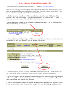
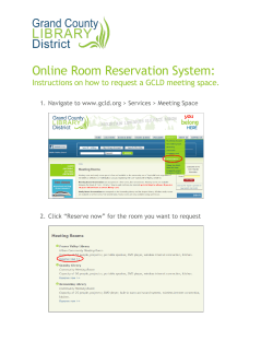


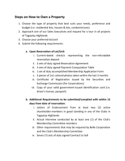


© Copyright 2026