
User Manual D-Link™ DGS-3100 SERIES GIGABIT STACKABLE MANAGED SWITCH
D-Link™ DGS-3100 SERIES
GIGABIT STACKABLE MANAGED SWITCH
User Manual
V2.20
Information in this document is subject to change without notice.
© 2007 D-Link Computer Corporation. All rights reserved.
Reproduction in any manner whatsoever without the written permission of D-Link Computer Corporation is strictly
forbidden.
Trademarks used in this text: D-Link and the D-Link logo are trademarks of D-Link Computer Corporation; Microsoft and
Windows are registered trademarks of Microsoft Corporation.
Other trademarks and trade names may be used in this document to refer to either the entities claiming the marks and names
or their products. D-Link Computer Corporation disclaims any proprietary interest in trademarks and trade names other than
its own.
FCC Warning
This equipment has been tested and found to comply with the limits for a Class A digital device, pursuant to Part 15 of the
FCC Rules. These limits are designed to provide reasonable protection against harmful interference when the equipment is
operated in a commercial environment. This equipment generates, uses, and can radiate radio frequency energy and, if not
installed and used in accordance with this user’s guide, may cause harmful interference to radio communications. Operation
of this equipment in a residential area is likely to cause harmful interference in which case the user will be required to
correct the interference at his own expense.
CE Mark Warning
This is a Class A product. In a domestic environment, this product may cause radio interference in which case the user may
be required to take adequate measures.
Warnung!
Dies ist ein Produkt der Klasse A. Im Wohnbereich kann dieses Produkt Funkstoerungen verursachen. In diesem Fall kann
vom Benutzer verlangt werden, angemessene Massnahmen zu ergreifen.
Precaución!
Este es un producto de Clase A. En un entorno doméstico, puede causar interferencias de radio, en cuyo case, puede
requerirse al usuario para que adopte las medidas adecuadas.
Attention!
Ceci est un produit de classe A. Dans un environnement domestique, ce produit pourrait causer des interférences radio,
auquel cas l`utilisateur devrait prendre les mesures adéquates.
Attenzione!
Il presente prodotto appartiene alla classe A. Se utilizzato in ambiente domestico il prodotto può causare interferenze radio,
nel cui caso è possibile che l`utente debba assumere provvedimenti adeguati.
VCCI Warning
May, 2008 P/N
Table of Contents
PREFACE..................................................................................................................................................................I
System Overview .................................................................................................................................................................. ii
Viewing the Device............................................................................................................................................................... ii
DGS-3100 Series Front Panel ........................................................................................................................................... ii
DGS-3100-24TG Front Panel ........................................................................................................................................... ii
Device Management Methods.............................................................................................................................................. iii
User Guide Overview........................................................................................................................................................... iv
Intended Audience ............................................................................................................................................................... iv
Notes, Notices, and Cautions ............................................................................................................................................... iv
Safety Cautions .................................................................................................................................................................... iv
General Precautions for Rack-Mountable Products ............................................................................................................. vi
GETTING STARTED................................................................................................................................................1
Using the Web-Based User Interface .................................................................................................................................... 1
Understanding the D-Link Embedded Web Interface ........................................................................................................... 1
Using the Tool Menu ............................................................................................................................................................ 3
Displaying the Stack Status............................................................................................................................................... 3
Locating Devices............................................................................................................................................................... 3
Backing up and Restoring Configuration Files ................................................................................................................. 4
Resetting the Device ......................................................................................................................................................... 5
Downloading the Firmware............................................................................................................................................... 6
Rebooting the System ....................................................................................................................................................... 8
Using the Web System Components..................................................................................................................................... 9
CONFIGURING BASIC CONFIGURATION ..........................................................................................................10
Viewing Device Information............................................................................................................................................... 11
Defining System Information.............................................................................................................................................. 13
Defining IP Addresses ........................................................................................................................................................ 14
Managing Stacking ............................................................................................................................................................. 15
Managing Stacking Modes.............................................................................................................................................. 15
Advanced Stacking.......................................................................................................................................................... 15
Stack Startup Process ...................................................................................................................................................... 17
Building Stacks – Quick Start ......................................................................................................................................... 19
Stack Management Examples ......................................................................................................................................... 20
Configuring Stacking ...................................................................................................................................................... 26
Defining Ports ..................................................................................................................................................................... 27
Configuring Port Properties ............................................................................................................................................ 27
Viewing Port Properties .................................................................................................................................................. 29
ARP Settings....................................................................................................................................................................... 30
Configuring User Accounts................................................................................................................................................. 31
Managing System Logs....................................................................................................................................................... 33
Configuring SNTP .............................................................................................................................................................. 34
Configuring Daylight Savings Time ............................................................................................................................... 36
Configuring SNMP ............................................................................................................................................................. 40
Defining SNMP Views ................................................................................................................................................... 41
Defining SNMP Groups.................................................................................................................................................. 42
Defining SNMP Users..................................................................................................................................................... 44
Defining SNMP Communities ........................................................................................................................................ 46
Defining SNMP Host Table ............................................................................................................................................ 47
Defining SNMP Engine ID ............................................................................................................................................. 49
Enabling SNMP Traps .................................................................................................................................................... 50
DHCP Auto Configuration.................................................................................................................................................. 51
Dual Image Services ........................................................................................................................................................... 52
Firmware Information ..................................................................................................................................................... 52
Config Firmware Image .................................................................................................................................................. 53
CONFIGURING L2 FEATURES.............................................................................................................................54
Enabling Jumbo Frames...................................................................................................................................................... 55
Configuring VLANs ........................................................................................................................................................... 56
Understanding IEEE 802.1p Priority .............................................................................................................................. 56
VLAN Description .......................................................................................................................................................... 56
Notes about VLANs on the DGS-3100 Series ................................................................................................................ 56
IEEE 802.1Q VLANs...................................................................................................................................................... 56
802.1Q VLAN Tags ........................................................................................................................................................ 58
Port VLAN ID................................................................................................................................................................. 59
Tagging and Untagging................................................................................................................................................... 59
Ingress Filtering .............................................................................................................................................................. 59
Default VLANs ............................................................................................................................................................... 60
VLAN and Trunk Groups ............................................................................................................................................... 60
VLAN Status................................................................................................................................................................... 60
Defining VLAN Properties ............................................................................................................................................. 61
Configuring GVRP ............................................................................................................................................................. 63
Defining Trunking............................................................................................................................................................... 65
Traffic Segmentation........................................................................................................................................................... 67
Configuring LACP.............................................................................................................................................................. 68
Defining IGMP Snooping ................................................................................................................................................... 69
Configuring Port Mirroring................................................................................................................................................. 72
Configuring Spanning Tree................................................................................................................................................. 74
Defining Spanning Tree Global Parameters.................................................................................................................... 75
Defining STP Port Settings ............................................................................................................................................. 77
Defining Multiple Spanning Tree Configuration Identification...................................................................................... 79
Defining MSTP Port Information ................................................................................................................................... 80
Defining Forwarding and Filtering ..................................................................................................................................... 82
Defining Unicast Forwarding.......................................................................................................................................... 82
Defining Multicast Forwarding....................................................................................................................................... 83
CONFIGURING QUALITY OF SERVICE ..............................................................................................................85
Understanding QoS ............................................................................................................................................................. 87
Defining Bandwidth Settings .............................................................................................................................................. 88
Configuring Storm Control ................................................................................................................................................. 89
Mapping Ports to Packet Priorities...................................................................................................................................... 90
Mapping Priority to Classes (Queues) ................................................................................................................................ 91
Configuring QoS Scheduling Mechanism........................................................................................................................... 92
Defining Multi-Layer CoS Settings .................................................................................................................................... 93
SECURITY FEATURES .........................................................................................................................................94
Configuring Safeguard Engine............................................................................................................................................ 95
Configuring Trust Host ....................................................................................................................................................... 96
Configuring Port Security ................................................................................................................................................... 97
Configuring Guest VLANs ................................................................................................................................................. 98
Configuring Port Authentication 802.1X ............................................................................................................................ 99
Configuring MAC Authentication (by using Guest VLAN, 802.1X and Radius pages) .............................................. 104
Defining RADIUS Settings........................................................................................................................................... 107
Configuring Secure Socket Layer Security ....................................................................................................................... 108
Configuring Secure Shell Security.................................................................................................................................... 110
Defining SSH Algorithm Settings................................................................................................................................. 111
Defining Application Authentication Settings .................................................................................................................. 113
Configuring Authentication Server Hosts ..................................................................................................................... 114
Defining Login Methods ............................................................................................................................................... 115
Defining Enable Methods ............................................................................................................................................. 117
Configuring Local Enable Password............................................................................................................................. 119
MONITORING THE DEVICE............................................................................................................................... 120
Viewing Stacking Information.......................................................................................................................................... 121
Viewing CPU Utilization .................................................................................................................................................. 122
Viewing Port Utilization ................................................................................................................................................... 123
Viewing Packet Size Information ..................................................................................................................................... 124
Viewing Received Packet Statistics .............................................................................................................................. 125
Viewing UMB_cast Packet Statistics............................................................................................................................ 126
Viewing Transmitted Packet Statistics.......................................................................................................................... 127
Viewing RADIUS Authenticated Session Statistics ......................................................................................................... 129
Viewing ARP Table .......................................................................................................................................................... 130
Viewing Router Ports........................................................................................................................................................ 131
Viewing Session Table...................................................................................................................................................... 132
Viewing IGMP Group Information................................................................................................................................... 133
Defining Dynamic and Static MAC Addresses................................................................................................................. 134
Viewing System Log......................................................................................................................................................... 136
MANAGING POWER OVER ETHERNET DEVICES.......................................................................................... 137
Defining PoE System Information .................................................................................................................................... 138
Displaying and Editing PoE System Information ............................................................................................................. 140
DEFINING ACCESS PROFILE LISTS................................................................................................................ 141
ACL Configuration Wizard............................................................................................................................................... 142
Defining Access Profile Lists............................................................................................................................................ 144
Defining Access Rules Lists ............................................................................................................................................. 157
Finding ACL Rules ........................................................................................................................................................... 160
TECHNICAL SUPPORT...................................................................................................................................... 171
DGS-3100 Series Gigabit Stackable Managed Switch User Manual
Preface
This preface provides an overview to the guide, and includes the following sections:
i
•
System Overview
•
Viewing the Device
•
Device Management Methods
•
User Guide Overview
•
Intended Audience
•
Notes, Notices, and Cautions
•
Safety Cautions
•
General Precautions for Rack-Mountable Products
DGS-3100 Series Gigabit Stackable Managed Switch User Manual
System Overview
The DGS-3100 series and the DGS-3100-24TG Gigabit Ethernet Switches enhance networks by providing a powerful
switch that eliminates network bottlenecks, enabling network administrators to fine tune network configurations.
The DGS-3100 series and the DGS-3100-24TG are perfect for departmental and enterprise connections, and are ideal for
backbone and server connections.
Viewing the Device
The devices described in this section are stackable Gigabit Ethernet Managed Switches. Device management is performed
using an Embedded Web Server (EWS) or through a Command Line Interface (CLI). The device configuration is performed
via an RS-232 interface. This section contains descriptions for the following:
•
DGS-3100 series Front Panel
•
DGS-3100-24TG Front Panel
DGS-3100 Series Front Panel
The DGS-3100 series provides 24/48 high performance 1000BASE-T ports. The 1000Base-T ports operate at 10/100/1000,
and connect to backbones, end-stations, and servers. The DGS-3100 series also provides 4 Mini-GBIC (SFP) combo ports
which connect fiber optic media to switches, servers, or network backbone. The DGS-3100 series provides an additional
RS-232 port (console port) for managing the switch via a console terminal or PC with a Terminal Emulation Program.
Figure 1 DGS-3100 Series 48 Port Front Panel
DGS-3100 Series Front Panel
The DGS-3100-24TG provides eight high performance 1000BASE-TX ports. The ports operate at 10/100/1000, and connect
to backbones, end-stations, and servers. The DGS-3100-24TG also provides 16 Mini-GBIC (SFP) ports which connect fiber
optic media to switches, servers, or network backbone. The DGS-3100-24TG provides an additional RS-232 port (console
port) for managing the switch via a console terminal or PC with a Terminal Emulation Program.
Figure 2 DGS-3100-24TG Front Panel
ii
DGS-3100 Series Gigabit Stackable Managed Switch User Manual
Device Management Methods
The DGS-3100 series and DGS-3100-24TG provide different methods for managing the device including:
•
Web Based Management Interface
•
SNMP-Based Management
•
Command Line Console
Web Based Management Interface
Once the device is installed, network mangers can configure the switch, monitor the LED panel, and display statistics
graphically via a web browser, including:
•
Netscape Navigator (version 7.0 and higher)
•
Microsoft® Internet Explorer (version 5.0).
•
Mozilla Firefox (version 2.0)
SNMP-Based Management
The system also supports SNMPv1, SNMPv2c, and SNMPv3. The SNMP agent decodes the incoming SNMP messages,
and replies to requests with MIB objects stored in the database. The SNMP agent updates the MIB objects to generate
statistics and counters.
Command Line Console
The device also supports device configuration using the Command Line Interface. A terminal is connected to device via the
serial console port.
iii
DGS-3100 Series Gigabit Stackable Managed Switch User Manual
User Guide Overview
This section provides an overview to the DGS-3100 series and the DGS-3100-24TG Switch Manual, including the guide
structure and a chapter overview:
•
Section 1, Getting Started — Provides general background for understanding and using the Embedded Web
System, including an explanation of the interface buttons and general system functions.
•
Section 2, Defining the Basic Device Configuration — Provides information for viewing system information,
defining IP addresses, managing stacking, defining ports, configuring SNMP management, and defining the system
time settings.
•
Section 3, Configuring L2 Features — Provides information for enabling and configuring Jumbo frames, VLANs,
Trunks (LAGs), Traffic Segmentation, Multicast forwarding, and Spanning Tree.
•
Section 4, Configuring Quality of Service — Provides information for ability to implement QoS and priority
queuing within a network.
•
Section 5, Security Features — Provides information for enabling and configuring device security.
•
Section 6, Monitoring the Device — Provides information for monitoring the device.
•
Section 7, Managing Power over Ethernet Devices — Provides information configuring the PoE function.
•
Section 8, Defining Access Profile Lists — Provides information for configuring the ACL.
User Guide Overview
The DGS-3100 series/DGS-3100-24TG User Guide contains information for configuring and managing the DGS-3100
series/DGS-3100-24TG Switches. This guide is intended for network managers familiar with network management concepts
and terminology.
Notes, Notices, and Cautions
NOTE: A NOTE indicates important information that helps you make better use of your device.
NOTICE: A NOTICE indicates either potential damage to hardware or loss of data and tells you
how to avoid the problem.
CAUTION: A CAUTION indicates a potential for property damage, personal injury, or death.
Safety Cautions
Use the following safety guidelines to ensure your own personal safety and to help protect your system from potential
damage. Throughout this safety section, the caution icon ( ) is used to indicate cautions and precautions that you need to
review and follow.
To reduce the risk of bodily injury, electrical shock, fire, and damage to the equipment, observe the following precautions.
iv
DGS-3100 Series Gigabit Stackable Managed Switch User Manual
v
•
Do not service any product except as explained in your system documentation. Opening or removing covers that
are marked with the triangular symbol with a lightning bolt may expose you to electrical shock. Only a trained
service technician should service components inside these compartments.
•
If any of the following conditions occur, unplug the product from the electrical outlet and replace the part or
contact your trained service provider:
– The power cable, extension cable, or plug is damaged.
–
An object has fallen into the product.
–
The product has been exposed to water.
–
The product has been dropped or damaged.
–
The product does not operate correctly when you follow the operating instructions.
•
Keep your system away from radiators and heat sources. Also, do not block the cooling vents.
•
Do not spill food or liquids on your system components, and never operate the product in a wet environment. If the
system gets wet, see the appropriate section in your troubleshooting guide or contact your trained service provider.
•
Do not push any objects into the openings of your system. Doing so can cause a fire or an electric shock by
shorting out interior components.
•
Use the product only with approved equipment.
•
Allow the product to cool before removing covers or touching internal components.
•
Operate the product only from the type of external power source indicated on the electrical ratings label. If you are
not sure of the type of power source required, consult your service provider or local power company.
•
To help avoid damaging your system, be sure the voltage selection Switch (if provided) on the power supply is set
to match the power available at your location:
– 115 volts (V)/60 hertz (Hz) in most of North and South America and some Far Eastern countries such as South
Korea and Taiwan
–
100 V/50 Hz in eastern Japan and 100 V/60 Hz in western Japan
–
230 V/50 Hz in most of Europe, the Middle East, and the Far East
•
Also be sure that attached devices are electrically rated to operate with the power available in your location.
•
Use only approved power cable(s). If you have not been provided with a power cable for your system or for any
AC-powered option intended for your system, purchase a power cable that is approved for use in your country. The
power cable must be rated for the product and for the voltage and current marked on the product's electrical ratings
label. The voltage and current rating of the cable should be greater than the ratings marked on the product.
•
To help prevent an electric shock, plug the system and peripheral power cables into properly grounded electrical
outlets. These cables are equipped with three-prong plugs to help ensure proper grounding. Do not use adapter
plugs or remove the grounding prong from a cable. If you must use an extension cable, use a 3-wire cable with
properly grounded plugs.
•
Observe extension cable and power strip ratings. Make sure that the total ampere rating of all products plugged into
the extension cable or power strip does not exceed 80 percent of the ampere ratings limit for the extension cable or
power strip.
•
To help protect your system from sudden, transient increases and decreases in electrical power, use a surge
suppressor, line conditioner, or uninterruptible power supply (UPS).
•
Position system cables and power cables carefully; route cables so that they cannot be stepped on or tripped over.
Be sure that nothing rests on any cables.
•
Do not modify power cables or plugs. Consult a licensed electrician or your power company for site modifications.
Always follow your local/national wiring rules.
•
When connecting or disconnecting power to hot-pluggable power supplies, if offered with your system, observe the
following guidelines:
– Install the power supply before connecting the power cable to the power supply.
–
Unplug the power cable before removing the power supply.
–
If the system has multiple sources of power, disconnect power from the system by unplugging all power cables
from the power supplies.
DGS-3100 Series Gigabit Stackable Managed Switch User Manual
Move products with care; ensure that all casters and/or stabilizers are firmly connected to the system. Avoid sudden stops
and uneven surfaces.
General Precautions for Rack-Mountable Products
Observe the following precautions for rack stability and safety. Also refer to the rack installation documentation
accompanying the system and the rack for specific caution statements and procedures.
Systems are considered to be components in a rack. Thus, "component" refers to any system as well as to various
peripherals or supporting hardware.
CAUTION: Installing systems in a rack without the front and side stabilizers installed could cause
the rack to tip over, potentially resulting in bodily injury under certain circumstances. Therefore,
always install the stabilizers before installing components in the rack.
After installing system/components in a rack, never pull more than one component out of the rack
on its slide assemblies at one time. The weight of more than one extended component could
cause the rack to tip over and may result in serious injury.
•
Before working on the rack, make sure that the stabilizers are secured to the rack, extended to the floor, and that
the full weight of the rack rests on the floor. Install front and side stabilizers on a single rack or front stabilizers for
joined multiple racks before working on the rack.
Always load the rack from the bottom up, and load the heaviest item in the rack first.
Make sure that the rack is level and stable before extending a component from the rack.
Use caution when pressing the component rail release latches and sliding a component into or out of a rack; the slide rails
can pinch your fingers.
After a component is inserted into the rack, carefully extend the rail into a locking position, and then slide the component
into the rack.
Do not overload the AC supply branch circuit that provides power to the rack. The total rack load should not exceed 80
percent of the branch circuit rating.
Ensure that proper airflow is provided to components in the rack.
Do not step on or stand on any component when servicing other components in a rack.
NOTE: A qualified electrician must perform all connections to DC power and to safety grounds. All
electrical wiring must comply with applicable local or national codes and practices.
CAUTION: Never defeat the ground conductor or operate the equipment in the absence of a
suitably installed ground conductor. Contact the appropriate electrical inspection authority or an
electrician if you are uncertain that suitable grounding is available.
CAUTION: The system chassis must be positively grounded to the rack cabinet frame. Do not
attempt to connect power to the system until grounding cables are connected. Completed power
and safety ground wiring must be inspected by a qualified electrical inspector. An energy hazard
will exist if the safety ground cable is omitted or disconnected.
vi
DGS-3100 Series Gigabit Stackable Managed Switch User Manual
Protecting Against Electrostatic Discharge
Static electricity can harm delicate components inside your system. To prevent static damage, discharge static electricity
from your body before you touch any of the electronic components, such as the microprocessor. You can do so by
periodically touching an unpainted metal surface on the chassis.
You can also take the following steps to prevent damage from electrostatic discharge (ESD):
1. When unpacking a static-sensitive component from its shipping carton, do not remove the component from the
antistatic packing material until you are ready to install the component in your system. Just before unwrapping the
antistatic packaging, be sure to discharge static electricity from your body.
2. When transporting a sensitive component, first place it in an antistatic container or packaging.
3. Handle all sensitive components in a static-safe area. If possible, use antistatic floor pads and workbench pads and
an antistatic grounding strap.
Battery Handling Reminder
CAUTION: This is danger of explosion if the battery is incorrectly replaced. Replace only with the
same or equivalent type recommended by the manufacturer. Discard used batteries according to
the manufacturer's instructions.
vii
DGS-3100 Series Gigabit Stackable Managed Switch User Manual
1
GETTING STARTED
To begin managing the device, simply run the browser installed on the management station and point it to the IP address
defined for the device. For example; http://123.123.123.123. Please note that the proxy for session connection should be
turned off.
NOTE: The Factory default IP address for the Switch is 10.90.90.90.
This section contains information on starting the D-Link Embedded Web Interface. To access the D-Link user interface:
1. Open an Internet browser. Ensure that pop-up blockers are disabled. If pop-up blockers are enabled, edit, add, and
device information messages may not open.
2. Enter the device IP address in the address bar and press Enter.
Using the Web-Based User Interface
The user interface provides access to various switch configuration and management windows, allows you to view
performance statistics, and permits you to graphically monitor the system status. The screen captures in this Guide represent the
DGS-3100-48 48 port device. The Web pages in the 24 port and the DGS-3100-24TG devices may vary slightly.
Understanding the D-Link Embedded Web Interface
The D-Link Embedded Web Interface Device Information Page contains the following information:
View
Description
Tree View
Displays the different system features, and configuration options.
Zoom View
Located at the top of the home page, the port LED indicators provide a visual
representation of the ports on the D-Link front panel.
Menu Information View
Located below the Zoom View, displays Save, Tool menu, Stack ID, and Logout buttons. Also
displays Up Time information and User Loggin Identification.
Device Information View
Located in the main part of the home page, the device view provides a view of the
device, an information or table area, and configuration instructions.
Stacking Status View
Located at the bottom left corner of the home page, the stacking status view provides
a graphic representation of the stacking links and ports status.
Table 1-1. Web Interface Views
1
DGS-3100 Series Gigabit Stackable Managed Switch User Manual
Figure 1-1. Device Information Page
The following table describes the main 6 areas on the Device Information Page:
View
Description
1. Tree View
Select the folder or window to be displayed. The folder icons can be opened to display the
hyperlinked menu buttons and subfolders contained within them.
2. Device
Information View
Presents Switch information based on the selection and the entry of configuration data
3. Menu
Information View
Presents the Save button, a menu for accessing device tools, and a menu for Stack ID
selection. The current Up Time and current User Loggin information is reported. The Logout button is
also here.
4. Zoom View
Presents a graphical near real-time image of the front panel of the Switch. This area displays
the Switch's ports and expansion modules, showing port activity, duplex mode, or flow
control, depending on the specified mode.
Various areas of the graphic can be selected for performing management functions, including
port configuration
5 Device
Application Buttons
Provides access to the device logout, and provides information about the Safe Guard mode
currently enabled on the device.
6 Stacking Status
View
Provides a graphic representation of the stacking links and ports status.
Table 1-2. Main Areas
2
DGS-3100 Series Gigabit Stackable Managed Switch User Manual
Using the Tool Menu
The tool menu contains menu options for:
•
Displaying the Stack Status
•
Locating Devices
•
Backing up and Restoring Configuration Files
•
Resetting the Device
•
Downloading the Firmware
•
Rebooting the System
Displaying the Stack Status
The Stacking Information Page provides specific information for stacked devices. For more information regarding the
stacking setup, see Managing Stacking section.
Locating Devices
The Device Locator Page enables locating system devices by activating LED locators. To locate devices:
1.
Click
> Device Locator. The Device Locator Page opens.
Figure 1-2. Device Locator Page
2.
3
Click
master unit.
. The LED locator is activated for 20 seconds On which the letter “L” will flash on the
DGS-3100 Series Gigabit Stackable Managed Switch User Manual
Backing up and Restoring Configuration Files
The Config Backup and Restore Page contains fields for downloading and uploading the configuration file from the device
through HTTP or TFTP server. To back up and restore configuration files:
1.
Click
> Config Backup & Restore. The Config Backup and Restore Page opens.
Figure 1-3 Config Backup and Restore Page
The Config Backup and Restore Page contains the following fields:
Field
Description
Http
Indicates that the system files are backed up or restored via an HTTP server. The possible
field values are:
Backup current setting to file — Backs up the current configuration files via the HTTP
server.
Restore saved setting from file — Restores the current configuration files via the HTTP
server.
TFTP
Indicates that the system files are backed up or restored via an TFTP server. The possible field
values are:
Server IP — Specifies the TFTP Server IP Address to which files are backed up or from
which they are restored.
File — Indicates the file that is backed up or restored.
Backup current setting to server — Backs up the current configuration files via the TFTP
server.
Restore saved setting from server — Restores the current configuration files via the TFTP
server.
2.
3.
Select HTTP or TFTP field.
Define the selected server method fields.
To backup files, click
.
To restore files, click
.
4
DGS-3100 Series Gigabit Stackable Managed Switch User Manual
Resetting the Device
The Factory Reset Page restores the factory defaults. To restore the device to the factory default settings:
1.
Click
> Reset. The Factory Reset Page opens:
Figure 1-4 Factory Reset Page
2.
5
Click
is updated.
. The factory default settings are restored once it completely reloaded, and the device
DGS-3100 Series Gigabit Stackable Managed Switch User Manual
Downloading the Firmware
The ‘Firmware Download’ web page is used to download the firmware files that will be used to manage the device.
NOTE: Firmware version 1.x.x supports 4 SKUs od DGS-3100 series: DGS-3100-24, DGS-310024P, DGS-3100-48 and DGS-3100-48P, Firmware version 2.x.x supports in addition the 5th SKU:
DGS-3100-24TG.
Firmware version 2.x.x includes as well additional features comparing to version 1.x.x, for more
details, please refer to the Release Notes.
When upgrading firmware from version 1.x.x to version 2.x.x on the switch, the user should
upgrade the boot software as well from version 1.0.0.3 to version 1.0.0.4
Upgrade Procedure – Important Notes:
ACL backward compatibility issue - In firmware 1.x.x, TCP/UDP ports of access profile are in hexadecimal instead of
decimal values. In version 2.x.x, TCP/UDP port value entries are in decimal value. However - if the user upgrades the
switch firmware from version 1.x.x to version 2.x.x, the value will be retained as hexadecimal value.
ACLs access rules priority did not work in firmware version 1.x.x. In firmware version 2.x.x, the priority is supported and it
is not allowed two identical access rules priority from different access profiles. If the user download configuration file from
version 1.x.x which including ACLs which has more than one rule, it might not work and there will be an error message.
The user can delete and create the ACLs again if he encountered a problem.
Tacacs/Radius backwards compatibility issue - In firmware version 1.x.x, it is possible to configure up to 4 Tacacs /Radius
servers. In firmware version 2.x.x, it is possible to configure up to 3 servers from each type. In addition to that it was not
required to configure priority to Tacacs servers in 1.x.x while in 2.x.x it is required. If the user configured 4 servers in
version 1.x.x and try to download the configuration to firmware 2.x.x, he will get an error message, the same event will
happened because of the Tacacs priority.
The Firmware Download Page enables downloading files either via an HTTP or a TFTP server. To download Firmware:
1.
Click
> Firmware Download. The Firmware Download Page opens:
Figure 1-5 Firmware Download Page
6
DGS-3100 Series Gigabit Stackable Managed Switch User Manual
The Firmware Download Page contains the following fields:
7
Field
Description
HTTP Download
Indicates that the Firmware file is downloaded via an HTTP server.
Unit — Indicates if the Firmware file is downloaded to a specific stacking member or to
All stacking members.
File — Indicates the Firmware file that is downloaded to the stack or specific device.
TFTP Download
Indicates that the Firmware file is downloaded via a TFTP server.
Unit — Indicates if the Firmware file is downloaded to a specific stacking member or to
All stacking members.
Server IP Address — Specifies the TFTP Server IP Address from which files are
downloaded.
File — Indicates the Firmware file that is downloaded to the stack or specific device.
2.
3.
4.
Select HTTP or TFTP Download field.
Define the Unit field.
For Http download, define the File field, or alternatively, browse to select the file.
5.
Click
. The Firmware is downloaded, and the device is updated.
DGS-3100 Series Gigabit Stackable Managed Switch User Manual
Rebooting the System
The System Reboot Page provides a method for selecting one, or all of the units to be rebooted. To reboot the system:
1.
Click
> System Reboot. The System Reboot Page opens:
Figure 1-6 System Reboot Page
The System Reboot Page contains the Select Unit to Reboot field. The possible values are:
Value
Description
All
Reboots all stacking members.
01 - 06
Reboots the specific stack member.
2.
3.
Define the Select Unit to Reboot field.
. The selected unit(s) is/are rebooted.
Click
8
DGS-3100 Series Gigabit Stackable Managed Switch User Manual
Using the Web System Components
The following table contains information regarding the list of buttons:
Component
Name
Description
Activate
Activates field commands
Add
Adds selected items
ALL
Selects all
Apply
Applies field settings
Backup
Evokes backup
Cancel
Cancels settings
Clear
Clears selected settings and fields
Clear All
Clears all settings and fields
Delete
Deletes selected fields
Delete VID
Deletes VLAN Identification
Download
Starts downloading system files.
Edit
Modifies configuration Information
Factory Reset
Resets the factory defaults
Find
Finds a table entry.
System Reboot
Reboot the system
Refresh
Refreshes device information.
Restore
Restores the specific configuration file.
View All Entry
Displays table entries.
Table 1-3. User Interface Buttons
9
DGS-3100 Series Gigabit Stackable Managed Switch User Manual
2
CONFIGURING BASIC CONFIGURATION
This section contains information for viewing device information, defining IP addresses, managing stacking, defining port
parameters, configuring system user accounts, configuring and managing system logs, defining the system time, and
configuring SNMP system management. This section contains the following topics:
•
Viewing Device Information
•
Defining System Information
•
Defining IP Addresses
•
Managing Stacking
•
Defining Ports
•
ARP Settings
•
Configuring User Accounts
•
Managing System Logs
•
Configuring SNTP
•
Configuring SNMP
•
DHCP Auto Configuration
•
Dual Image Services
10
DGS-3100 Series Gigabit Stackable Managed Switch User Manual
Viewing Device Information
The Device Information Page contains parameters for configuring general device information, including the system name,
location, and contact, the system MAC Address, System Up Time, and MAC addresses, and both software, boot, and
hardware versions.
In addition the Device Information Page provides shortcuts to device feature pages. To define the general system
information:
•
Click DGS-3100-xx in the Tree View. The Device Information Page opens:
Figure 2-1 Device Information Page
The Device Information Page contains the following fields:
Field
Description
Device Type
Displays the factory defined device name and type.
System Contact
Displays the name of the contact person. The field range is 0-31 characters.
System Name
Displays the user-defined system name. The field range is 0-31 characters.
System Location
Displays the location where the system is currently running. The field range is 0-31
characters.
Firmware Version
Displays the installed software version number.
Hardware Version
Displays the installed device hardware version number.
System Time
Displays the system time. The field format is Day/Month/Year.
System Up Time
Displays the amount of time since the most recent device reboot. The system time is
displayed in the following format: Days, Hours, Minutes, and Seconds. For example, 41
days, 2 hours, 22 minutes and 15 seconds.
11
DGS-3100 Series Gigabit Stackable Managed Switch User Manual
Field
Description
Boot Version
Displays the installed device boot version number.
MAC Address
Displays the MAC address assigned to the device.
IP Address
Displays the IP address assigned to the device.
Subnet Mask
Displays the subnet mask assigned to the device.
Default Gateway
Displays the device default gateway assigned to the device.
Login Timeout (minutes)
Indicates the amount of time after which if no user activity occurs, the device times out.
The default is 10 minutes.
Time Source
Provides a shortcut to viewing the system clock settings.
802.1D Spanning Tree
Indicates if STP is enabled on the device, and provides a shortcut to viewing the STP
settings.
DHCP Client
Indicates if DCHP Client is enabled on the device, and provides a shortcut to viewing the
DHCP Client settings.
Safeguard Engine
Indicates if the Safeguard Engine is enabled on the device, and provides a shortcut to
viewing the Safeguard Engine settings.
SNMP Trap
Indicates if SNMP Traps are enabled on the device, and provides a shortcut to viewing
the SNMP Traps settings.
SSL
Indicates if Secure Socket Layer (SSL) is enabled on the device, and provides a shortcut
to viewing the SSL settings.
GVRP Setting
Indicates if Group VLAN Registration Protocol is enabled.
Jumbo Frames
Indicates if Jumbo Frames are enabled on the device, and provides a shortcut to viewing
the Jumbo Frames settings.
BPDU Forwarding
Indicates if BPDU Forwarding is enabled on the device, and provides a shortcut to
viewing the BPDU Forwarding settings.
IGMP Snooping
Indicates if IGMP Snooping is enabled on the device, and provides a shortcut to viewing
the IGMP Snooping settings.
Broadcast Storm Control
Indicates if Broadcast Storm Control is enabled on the device, and provides a shortcut to
viewing the Broadcast Storm Control settings.
802.1X Status
Indicates if 802.1X is enabled on the device, and provides a shortcut to viewing the
802.1X settings.
SSH
Indicates if Secure Shell Protocol (SSH) is enabled on the device, and provides a shortcut
to viewing the SSH settings.
Port Mirroring
Indicates if Port Mirroring is enabled.
To view settings for a device feature:
1. Select a device feature under the Device Status and Quick Configuration Section.
2. Click setting next to the feature name. The configuration page for the selected device feature opens.
12
DGS-3100 Series Gigabit Stackable Managed Switch User Manual
Defining System Information
The System Information Page provides device information about specific stacking members. To view system information:
1. Click Configuration > System Information. The System Information Page opens:
Figure 2-2 System Information Page
The System Information Page contains the following fields:
Field
Description
Unit ID
Displays the stack unit ID.
MAC Address
Displays the MAC address assigned to the device
Firmware Version
Displays the stacking member’s software version number.
Hardware Version
Displays the stacking member’s hardware version number.
System Contact
Defines the name of the contact person. The field range is 0-160 characters.
System Name
Defines the user-defined system name.
System Location
Defines the location where the system is currently running. The field range is 0-160
characters.
Login Timeout (minutes)
Defines the amount of time the device times out when no user activity occurs. The default is
10 minutes.
13
2.
3.
Define the System Name field.
Define the System Location and Login Timeout (minutes) fields.
4.
Click
. The system information is defined, and the device is updated.
DGS-3100 Series Gigabit Stackable Managed Switch User Manual
Defining IP Addresses
The IP Address Page contains fields for assigning IP addresses. Packets are forwarded to the default IP when frames are
sent to a remote network via the Default Gateway. The configured IP address must belong to the same IP address subnet of
one of the IP interfaces. The Dynamic Host Configuration Protocol (DHCP) assigns dynamic IP addresses to devices on a
network. DHCP ensures that network devices can have a different IP address every time the device connects to the network.
1. Click Configuration > IP Address. The IP Address Page opens:
Figure 2-3 IP Address Page
The IP Address Page contains the following fields:
Field
Description
Static
When selected, the IP address is static and user-defined in the IP Address field. This is the
default value.
DHCP
When selected, the IP address is retrieved from a DHCP server.
IP Address
Defines the IP address. This field is active if the IP address is static.
Subnet Mask
Defines the address mask that manages sub-netting on the network. The default value is
255.0.0.0.
Gateway
Defines the default gateway. The default gateway manages connections to other subnets
and other networks.
Management VLAN VID
Defines the management VLAN’s VID.
2.
3.
4.
Select the IP address type in either the Static or DHCP fields.
If Static is the defined IP address type, define the IP Address field.
Define the Subnet Mask, Gateway, and Management VLAN VID fields.
5.
Click
. The IP address information is defined, and the device is updated.
14
DGS-3100 Series Gigabit Stackable Managed Switch User Manual
Managing Stacking
Stacking enhances network flexibility by building virtual switches with more ports then are available in a single device.
Stacks are managed by stacking member which called Stack Master., All other stacking members serve as ports only.
The following paragraphs provide a stacking explanation for DGS-3100 series and include the following topics:
•
Managing Stacking Modes
•
Advanced Stacking
•
Building Stacks – Quick Start
•
Stack Management Examples
•
Configuring Stacking
Managing Stacking Modes
A switch may operates in one of the following modes:
•
Stand-Alone- Switches operating in stand-alone mode run as an independent unit. All ports of a stand-alone switch
operate as normal Ethernet links except the HX ports which are Disabled.
NOTE: The DGS-3100 series family stacking connections have two HX ports.
•
Stacking - Switches operating in Stack mode run as organized group member of switches known as a Stack. A
stack consists of one Stack Master, a Backup Master, and up to four Stack Member Switches. However, in specific
scenarios, a single unit can be considered a Stack of One. A Stack of One is a single unit which does not connected
to any other stacking members.
Either stacking or stand-alone modes can be selected by the user before the next software boot which using CLI or the
Embedded WEB Interface, the new mode takes effect after the unit is rebooted. If the unit is reset to the factory defaults, the
unit is reloaded in stacking Auto-Numbering mode.
Advanced Stacking
This section provides information for understanding advanced stacking concepts, including:
•
Unit ID and how they are allocated
• Stacking member start up process.
This section contains the following topics:
•
Allocating Unit IDs
•
Assigning Unit IDs
Allocating Unit IDs
Switches are shipped from the factory without a Unit ID and in Auto Assign mode. All switches must be assigned a Unit ID
before switches can operate as stacking members. More than one stacking member cannot receive the same Unit ID. Unit
IDs are assigned by:
15
•
Assigned by the system administrator. Unit IDs that are assigned by the system administrator and can only be
changed manually by the system administrator.
•
If the system administrator does not set the Unit IDs manually, the Auto Assign initializes the switches when they
are powered up. From the switches who are automatically assigned a Unit ID, one of the stacking members is
assigned the Unit ID 1. That stacking member is the Stack Master. If there were more than one switch in the stack,
there is a Master Election and Backup Master Election process. Following the Master Election process, the other
stacking members are assigned a Unit ID by the stack Master. For more information on the Master Election process,
please see Electing a Stacking Master.
DGS-3100 Series Gigabit Stackable Managed Switch User Manual
Stacking members maintain the assigned Unit ID even after the stacking member is rebooted. The Stack Master may
reallocate IDs during system initialization to resolve duplicate ID conflicts. Manually assigned IDs cannot be changed by
the Stack Master, even if there is a conflict.
Unit ID assignments or modifications are effective only during system initialization, and do not occur during the system uptime.
Stacking members do not have to be numbered in sequence, and can be interconnected, as long as each stacking has a
unique ID, and at least, one stacking member serves as the Stack Master.
Assigning Unit IDs
Each stacking member has an assigned unique Unit ID. Unit ID numbers are assigned as follows:
•
Unit ID 1 - Assigned to the Stack Master. The Stack Master is indicated by the Master LED on front which is lit
solid green.
•
Unit ID 2 - Assigned to the Backup Master
•
Unit ID 3, 4, 5, and 6 - Assigned to Stacking members.
NOTE: There are cases in which a unit to which Unit ID 1 is assigned is not the stack Master but a
Backup Master.
This section contains the following topics:
•
Defining a Stacking Master
•
Defining a Stacking Back Up Master
•
Defining Stacking Members
•
Master Enabled Stacking Members
•
Electing a Stacking Master
Defining a Stacking Master
The stacking member assigned the Unit ID1 operates as the Stack Master.
The Stack Master provides a single point of control, configuration, and management for the entire stack. In addition, the
Stack Master stores all stack member configuration. The individual stacking members do not store any configuration
information.
Defining a Stacking Back Up Master
The stacking member assigned the Unit ID 2 is defined as the stack’s Backup Master.
In addition to being a stack member, Backup Master serves as a backup in case the Stack Master fails or disconnected. If the
Stack Master fails or disconnected, the Backup Master takes over as the Stack Master.
The Stack Master stores an active configuration which copied on the Backup Master. The active configuration copy is used
if the Backup Master takes over for the Stack Master. Only the configuration file is copied. Any dynamically filled tables,
for example, learnt address, are not copied from the Stack Master to the Backup Master. If the Backup Master takes over the
role of Stack Master, the Backup Master builds new dynamic tables.
Defining Stacking Members
Switches assigned the Unit IDs 3,4,5,6 are called stacking members. The Stack Master (or Backup Master if the Stack
Master fails) manages the stack members operation. Stacking members cannot be directly managed or configured. If neither
the Stack Master nor the Backup Master were operating, the stacking members cannot function.
Master Enabled Stacking Members
Only Stacking members assigned to Unit ID 1 or 2 are called Master Enabled stacking members. Only the Master Enabled
stacking members participate in the Master Election process, and therefore can become master or backup master (that means
the s with assigned IDs of 3, 4, 5 and 6 can never become neither a master nor a backup master unless their ID is changed by
the system administrator or reset to the factory default firstly).
16
DGS-3100 Series Gigabit Stackable Managed Switch User Manual
Electing a Stacking Master
Whenever a stacking member (or more than one) comes up, one of the stacking members is elected to be the stack Master.
The Stack Master is selected as follows:
•
If one of the master enabled stacking members in the stack was set to Force Master by the system administrator
(through the GUI – Stacking Master selector), that master enabled stacking member is the Stack Master. Stacking
members which are defined as Force Master stacking members are manually selected as the Stack Master. Only a
master enabled stacking member can be selected as the Force Master.
•
If the stack contains more than one stacking member whose Unit ID is either 1 or 2, then one of the stacking
members are elected the Stack Master. It does not matter if the Unit ID was originally automatically or manually
assigned. These stacking members are called Master Enabled. If there is only one stacking member, that stacking
member is selected as the Stack Master, even if the stacking member’s Unit ID is 2.
•
If there are more than one stacking members, the two stacking members decide which stacking member is elected
Stack Master by checking:
– Which stacking member has been running for a longer time. The up-time is measured in increments of 10
minutes. The stacking member running the longest is elected the Stack Master.
–
If they have been running for the same amount of time, the stacking member with the Unit ID 1 is the stack
Master.
–
If both stacking members have been running for the same amount of time, and both stacking membes have the
same Unit ID, the stacking members with the lowest MAC addressis selected as the Stack Master. The other
unit is rebooted and is assigned the Unit ID 2.
–
If the stack contains one or more stacking members set to the factory default states, and there is no Unit ID
assigned to a stacking member, then the Stack Master is one of these stacking members. The stacking member
selected to be the Master is the stacking member running for the longest time. If all stacking members are
running the same amount of time, the stacking member with the lowest MAC address is selected as the Stack
Master.
The Master Election results in an elected Stack Master. The Stack master has a Unit ID of 1 and the Backup Master has a
Unit ID of 2 (if a Backup Master was included in the stack).
If a Master Enabled stacking member, a Unit ID of 1 or 2, is added to a stack and powered on, the newly added switch
invokes Master Election process. The Master Election process occurs even though the stack has an elected master. However,
the newly added switch loses in the election process (lower up-time) and joins the stack as a stacking member or Backup
Master.
Stack Startup Process
When a stacking member is initialized, either powered up or rebooted, the stacking member goes through the same exact
process including:
•
Discovering the Stacking Master.
•
Allocating Unit IDs/Resolving Unit ID Conflicts
•
Unit and Stacking Port Configuration
Discovering the Stacking Master
When a stacking member is initialized in stack mode, the stacking member’s behavior depends on its Unit ID.
17
•
If the stacking member does not have a current Unit ID the stacking member operates in Factory Default mode. If
there is a Stacking Master, the stacking member is assigned a Unit ID through Unit ID Allocation. The stacking
members receive a Unit ID from the Stacking Master. If the stack does not have a Stacking master then the switch
participates in Master-Election, and may be elected either the new Stacking Master or Backup Master.
•
If the stacking member’s current Unit ID is 1 or 2, the stacking member participates in the Master Election. For
example, the Unit ID was previously allocated, or the stacking member was in a different stack.
•
If the stacking member has a current Unit ID the stacking members attempts to use the Unit ID in the new stack. If
the stacking member current ID is 3, 4, 5, or 6, then the stacking members attempts to connect to the running Stack
Master. The new stacking member does not proceed to the next stage until there is contact with the Stack Master.
DGS-3100 Series Gigabit Stackable Managed Switch User Manual
These stacking members do not participate in the Master Election process, and if no Stack Master is present, the
stacking members’ network ports are shut down. Only the stacking ports are operational.
Both the Stack Master and all other stacking members carry out a continuous process of Master Discovery by frequently
exchanging stack control messages. This allows the stacking members to discover when a stacking member fails or is
unreachable.
Allocating Unit IDs/Resolving Unit ID Conflicts
Once the Stack Master is elected, it allocates the Unit IDs to the stacking members that do not have a Unit ID. Stacking
members that do not have a Unit ID operate in the Factory Default mode.
In addition, the stack Master attempts to resolve all duplicate Unit IDs occurrences among stacking members. The Stack
Master reallocates the duplicate Unit ID if there are available Unit IDs.
If two stacks are merged, stacking units that were initially in the Stack Master’s sub-group retain their Unit ID. New
stacking member are allocated new Unit IDs.
If a conflict occurs after the stacking members are rebooted, the following occurs:
•
If both duplicate stacking members are in Auto Assign mode, then the Unit ID is assigned by the MAC address.
The stacking member with the lowest MAC address maintains its Unit ID. The other stacking member is assigned a
new Unit ID.
•
If one of the stacking members with duplicate Unit IDs is in Auto Assign mode and the other stacking member is in
manual mode, the stacking member in Manual mode maintains its Unit ID, The other stacking member is assigned
a new Unit ID. .
Stacking members are shut down if:
•
If both duplicate stacking members are in Manual mode then both stacking members are shut down.
•
If the Stack Master is able to allocate a Unit ID to each stacking member, then all stacking members operate as a
stack. If the Stack Master is unable to allocate a Unit ID to any stacking member, that stacking member is
effectively shut down and does not participate in the stack.
•
Stacking members with a conflicting manually set ID are shut down as the Stack Master cannot override the system
administrator’s Unit ID assignment to resolve the conflict.
•
If there are more stacking members than the maximum number allowed in a stack, and the incoming stacking
members are already in Factory Default mode, the Stack Master is elected following Master Discovery and Master
Election processes. All other stacking members are shut down in some extreme cases, due to during the boot
process, where some stacking members may be connected and join the stack. If the new stacking members are
already assigned a Unit, then the new stacking members cannot join the stack. The switches are remains shut down.
If a stacking member is shut down, the stacking members stacking links are inactive. Moreover, if the stacking members are
connected in a chain topology, the shut down of one stacking member breaks the chain. This may cause other stacking
members to be disconnected and shut down if the stacking members have no active link to the Stack Master.
Unit and Stacking Port Configuration
Each stacking member has a Unit ID; one of the stacking members is the stack Master, and, possibly, one of the stacking
members serves as Backup Master. The Stack Master now configures each stacking member according to the Configuration
file stored on the Stack Master.
If the stack has a Backup Master the Configuration file are also be copied to the Backup Master.
Once all the stacking members are configured, the stack proceeds to a normal operational mode. If any change is made to
the system configuration, the change is stored by the stack Master and is copied to the Backup Master.
18
DGS-3100 Series Gigabit Stackable Managed Switch User Manual
Building Stacks – Quick Start
The DGS-3100 series supports the following stacking scenarios:
•
Building a new stack from scratch
• Increasing the stack by adding units to an existing stack
This section contains the following topics:
•
Stack Resiliency
•
Managing a Self-Ordered Stack
•
Managing a New Manually Ordered Stack
Stack Resiliency
Topologies of stack can be either Ring or Chain. Best practice is to configure the stack in Ring topology, due to the high
resiliency in case of unit failure or stacking link failure.
Additionally, in case of redundant power supply usage it is recommended to make sure that Master and Backup Master s are
connected to a redundant power supply.
Managing a Self-Ordered Stack
This section describes managing a self-ordered stack. Self–ordered stacks are automatically assigned Unit IDs by the system
through the Master Election process. This section contains the following topics:
•
Building a New Self-Ordered Stack
•
Adding Members to a Self Ordered Running Stack
Building a New Self-Ordered Stack
To build a self ordered stack:
1. Connect the units physically through the stacking ports.
2. Turn on the units. After a short interval the stack will become operational with one of the units selected as the
Master of the stack. The Master and Backup selection is known as Master Election. Master Election takes place if
there are one or more eligible candidates contending to be the Master unit. The Master Unit is indicated by the
green Master LED on the front panel. The Master LED is located near the Unit ID LEDs. If a serial console is
connected, the serial cable must be connected to the Stack Master console port since the only operational console
port in the stack is the one of the Master unit.
NOTE: To reset the stacking members to the factory defaults, press the Reset button for at least 5
seconds.
Adding Members to a Self Ordered Running Stack
1. Reset the new stacking units to the factory defaults by pressing the Reset button (optional).
2. Connect the stacking members physically to the stack.
3. Turn on the switches, the new units will become stacking members.
Managing a New Manually Ordered Stack
System administrator can also manually assign Unit IDs to stacking members. System administrator has to assign a unique
Unit ID from 1 to 6 to each stack member.
A Unit ID that is manually assigned is not subject to automatic numbering. The Unit IDs are assigned as follows:
19
•
Unit ID 1 – Assigned to the Stacking Master. The Stack Master is indicated by the Master LED on front which is
lit solid green.
•
Unit ID 2 - Assigned to the Backup Master
•
Unit ID 3 4, 5, 6 –Assigned to the Stacking member.
DGS-3100 Series Gigabit Stackable Managed Switch User Manual
This section contains the following topics:
•
Building New Manually Ordered Stacks
•
Adding Stacking Members to an Existing Manually Ordered Stack
Building New Manually Ordered Stacks
To build new a self ordered stack:
1. Connect the units physically through the stacking ports.
2. Turn on the units, one at a time.
3. Assign the Stack Master the Unit ID of 1 using a Stack Management Interfaces either the console port, Telnet, or
Embedded Web Interface.
4. Assign the Backup Master the Unit ID of 2 using a Stack Management Interfaces either the console port, Telnet, or
Embedded Web Interface.
5. Assign the remaining stacking members using a Stack Management Interfaces either the console port, Telnet, or
Embedded Web Interface.
6. Ensure that none of the stacking members have the same Unit ID.
7. Reboot all the stack units.
Adding Stacking Members to an Existing Manually Ordered Stack
To add units to an existing manually ordered stack:
1. Reset the new stacking units to the factory defaults by pressing the Reset button.
2. Connect the stacking members physically to the stack.
3. Turn on the switches, the new units become stacking members, but with automatically assigned Unit IDs.
4. Reassign the Unit ID manually to each of the newly added stacking members using a Stack Management Interfaces
either the console port, Telnet, or Embedded Web Interface. This step is optional, and the stack is operational even
if some unit IDs were manually configured while others are self-assigned.
5. Reboot the stacking members to ensure the Unit ID is permanent.
Stack Management Examples
This section contains information for troubleshooting stacking, and includes the following topics:
•
Replacing Failed Stacking-Members in a Running Stack
•
Replacing a Failed Stack Master
•
Dividing Stacks
•
Merging Stacks
•
Stacking Cable Failure
•
Inserting Excess Stacking Members
Replacing Failed Stacking-Members in a Running Stack
This example assumes that a stacking member, other than master, has failed in a running stack, when the system
administrator is notified of the system failure the stacking member is removed and replaced with a new switch.
When the stacking member fails, the Stack Master identifies the failed stacking member using the Master Discovery process.
The Stack Master recognizes that the stacking member no longer responds. If the stack topology was ring topology, the
Stack Master directs all other stack members to route traffic around the failed stacking member. At the same time the Stack
Master notifies the system administrator of the failure using SYSLOG messages and SNMP traps.
When the failed stacking member is disconnected from the stack, all traffic is routed around the failed stacking member as
stated above. As long as all other stacking connections are intact, the stack continues to run.
When a new stacking member is inserted and the stack is powered up, the following occurs:
•
The new stacking member which is in stacking mode, performs the Master Discovery process, and perhaps
participates in a Master Election .For more information on the Master Election process, see Electing a Stacking
Master.
20
DGS-3100 Series Gigabit Stackable Managed Switch User Manual
•
–
If the new stacking member has a Unit ID of 1 or 2, i.e. the stacking member is a master enabled unit, the new
stacking member initiates the Master Election process. However, since the running Stack Master has a longer
up-time, it remains the Stack Master and the new stacking member does not become a new Stack Master.
–
If the new stacking member has a Unit ID of 3 to 6, the new unit attempts to become a stacking member, and
is subject to the already running Stack Master. The Master Election process does not occur.
The Stack Master performs a Unit ID Allocation and Conflict Resolution process.
– If the new stacking member was in Factory Default mode (the unit does not have an assigned Unit ID). The
new stacking member is assigned the lowest available Unit ID by the Stack Master. It is strongly
recommended that automatic assigned Unit ID mode be used since it provides improved stack resiliency.
–
If the new stacking member already has an assigned Unit ID, and that Unit ID is unused in the current stack,
the new stacking member retains its assigned Unit ID. The Stack Master applies any configuration relevant to
that Unit ID.
–
If the new stacking member already has an assigned Unit ID, and that Unit ID conflicts with an existing Unit
ID the Stack Master reallocates a new Unit ID to the new stacking member. , The lowest available Unit ID is
applied to the new stacking member. This occurs only if new stacking member does not have a manually
assigned Unit ID, which the Stack Master cannot change.
–
If the new stacking member cannot be assigned an available Unit ID, then the new stacking member is
effectively shut down and cannot join the stack. For example, the stacking member replacement can only occur
if the new stacking member has a manually assigned Unit ID.
•
The Stack Master now performs Unit and Stacking Port Configuration for the new stacking member.
•
Any configuration information which the Stack Master stores that is relevant to the Unit ID is assigned to the new
stacking member. If the new stacking member was assigned the same Unit ID of the replaced stacking member,
then the new stacking member receives the same configuration as the failed stacking member. If the new stacking
member is identical to the replaced stacking member, the entire configuration of the replaced stacking member is
applied to the new stacking member. The stack reverts to the stacking state it was running in before stacking
member failed. However, sometimes the new stacking member is not identical to the failed stacking member. The
Stack Master applies the configuration as follows:
•
If a 24-port switch replaces a failed 48-port switch, then the new stacking member’s ports are configured according
first 24 ports configuration of the failed stacking member.
NOTE: The 48 port configuration of the failed stacking member is recorded, even though only the
first 24 port configuration is currently applied. If a 48 port switch is inserted and assigned the
same Unit ID, the switch is configured with the port configuration of the original 48 port stacking
member.
•
If a 48-port stacking member replaces a 24-port stacking member, then the first 24 ports of thenew stacking
member are configured according failed stacking member’s ports configuration. The remaining new stacking
member ports are configured with the switch’s default settings.
Replacing a Failed Stack Master
This example assumes that that a stacking member acting as the Stack Master has failed in a running stack. When the
system administrator is notified of the Stack Master failure and replaces existing Stack Master with a new switch.
When the Stack Master fails, the stack’s Backup Master recognizes the failure and that the Stack Master no longer responds
and assumes the role of Stack Master. The Backup Master uses Master Discovery process to identify the failure. In case of
Ring topology the Backup Master directs all other stack members to route traffic around the failed stacking member. At the
same time the Backup Master notifies the system administrator of the failure using SYSLOG messages and SNMP traps.
When the failed stacking member is disconnected from the stack, all traffic is already routed around the failed stacking
member. If all other stacking connections are left intact, the stack keeps running. When a new stacking member is inserted
and powered up, the following occurs:
•
21
The new stacking member performs Master Discovery process, and participates in a Master Election process. For
more information on the Master Election, see Electing a Stacking Master.
– If the new stacking member has a Unit ID of 1 or 2, i.e. the stacking member is a master enabled; Master
Election process is initiated. Since the running stack Backup Master has a longer run timeand if the Backup
Master has been running for more then 10 minutes, the Backup Master remains the elected Stack Master. The
new stacking member does not become the new Stack Master. This may result in new stacking member using
DGS-3100 Series Gigabit Stackable Managed Switch User Manual
Unit ID 1, and serving as the stack Backup master, while the already running stacking member with Unit ID 2
remains the active Stack Master.
•
•
•
The Stack Master performs Unit ID Allocation and Conflict Resolution process.
– If the new stacking member is in the Factory Default mode, the new stacking member is assigned the lowest
available Unit ID by the Stack Master. It is strongly recommended that Auto Assign mode is used to assign the
Unit ID. The Auto Assign mode provides better stack resiliency.
–
If the new stacking member already has an assigned Unit ID, and that Unit ID is unused in the current stack,
the incoming stacking member is assigned Unit ID. The Stack Master applies any device configuration to the
new stacking member.
–
If the new stacking member already has an assigned Unit ID, and that UnitID conflicts with an existing Unit
ID the Stack Master reallocates a new Unit ID to the new stacking member. The lowest available Unit ID is
applied to the new stacking member. This occurs only if new stacking member does not have a manually
assigned Unit ID, which the Stack Master cannot change.
–
If the new stacking member cannot be assigned an available Unit ID, then the new stacking member is
effectively shut down and cannot join stack. For example, if stacking member replacement that can only occur
if the new stacking member has a manually assigned Unit ID.
The Stack Master performs Unit and Stacking Port Configuration for the new stacking member.
Any configuration information the Stack Master retains that is relevant to the Unit ID of the new stacking member
is applied. If the new stacking member was assigned the same Unit ID of the replaced stacking member, then the
new stacking member receives the same switch configuration as the failed stacking member, described in
Replacing Failed Stacking-Members in a Running Stack.
Dividing Stacks
This example assumes that a working stack is divided into two groups. The stack is divided either by a failed stacking link
connected to two stacking members in the stack or by a failed stacking members in a chain topology which causes
disconnection between two units in the stack. In this case we should consider each sub-group as an independent running
stack configuration. For each sub-group we should consider three sub options:
•
Both the Stack Master and the Backup Master are part of the sub-group.
•
Either the Stack Master or the Backup Master is part of the sub-group.
• Neither the Stack Master nor the Backup Master is part of the sub-group.
When a stack is split into two parts, the following occurs in each partial stack according to the following scenario:
Both the Stack Master and the Backup Master are part of the sub-group.
Nothing changes, except the Stack Master recognizes the missing stacking members as removed stacking members and
routes traffic around them.
Since both the Stack Master and Backup Master are in this stacking section, this section is operating and the other section
cannot operate.
The following occurs when the stack is divided and both the Master and Backup master are in the sub-group:
•
•
The Master Discovery, Master Election and Unit ID Allocation & Duplicate Unit ID Conflict Resolution processes
are performed, resulting in the following:
– Any configuration information stored by Stack Master, which remained in the group, that is relevant to the
stacking members remains unchanged.
–
Topology information, inter-stacking member forwarding information for transmitting traffic to any other
stacking member, managed by the Stack Master includes only stacking members that remain connected after
the stack is divided.
–
The divided stack continues to operates normally, the only difference is there are less stacking members than
prior to the stack division.
–
No Unit ID changes are performed in each divided stack.
–
The Stack Master notifies the system administrator using SYSLOG messages and SNMP traps of the removed
stacking members. In addition the Stack Master also notifies the system administrator whichd ports belong to
unreachable stacking members and are reported as Not Present.
Either the Stack Master or the Backup Master remain in the divided group
22
DGS-3100 Series Gigabit Stackable Managed Switch User Manual
–
If the Stack Master remains in this sub-group, the behavior is the same as described above. If the Backup
Master remains in this sub group the behavior is the same as described in0 - Replacing a Failed Stack Master .
NOTE: If a stack is divided into two parts with one section which containing the Stack Master, and the
other section - Backup Master was operate.
The following occurs if either the Stack Master or the Backup Master remains in the divided group:
•
The Master Discovery, Master Election and Unit ID Allocation & Duplicate Unit ID Conflict Resolution processes are
T
performed, resulting in the following:
–
When the stack is divided and if the Stack Master remains in the split stack, the Stack Master recognizes that
the stacking units were no longer responds. This occurs using the Master Detection Process. The Stack Master
notifies the system administrator using SYSLOG messages and SNMP traps of the removed stacking members.
In addition the Stack Master also notifies the system administrator whichd ports belong to unreachable
stacking members and are reported as Not Present.
–
if the Backup Master remains in the split stack, when the stack is divided, the Backup Master identifies this as
of the Stack Master failing. The Backup Master takes over and manages the remaining stacking members as a
stack. The Backup Master retains the same Unit ID as before the stack was divided. Since the Backup Master
was not acting as the Stack Master prior to the split, the Back Master initiates a Topology Database and port
learning process. Traffic can be halted for a short period until the stack is synchronized, i.e., stacking member
and port configuraiton is completed. New stacking members are learnt by the Backup Master are notified to
the system administrator using SYSLOG messages and SNMP traps.
–
The divided stack continues to operate normally, the only difference is there are less stacking members than
prior to the stack division.No Unit ID changes are performed in each the divided stacks.
–
Even if each stacking section has a Stack Master, one section retains the Stack Master and the other section the
Backup Master, both stacks have the same configuration and the same IP address.
NOTE: If both stacks have the same IP Address, this can lead to network problem. There is
no way for users to connect to any stacks through the stack IP address
If neither the Stack Master nor the Backup Master remain in the divided group.
•
This is identical to failed Stack Master, where no backup is available.
•
Stacking members whose Unit IDs are 3, 4, 5 or 6 in original stack do not renumber themselves. The stacking
members’ network ports remains shut down until a Stack Master is enabled, is connected and is operating as the
Stack Master .The Master-Discovery process recognized that the Stack Master has been separated from the stack.
•
The stacking members lose connection with the Stack Master. Since the stacking members started as a running
stack, and the stacking members are not in the Factory Default Mode, the stacking members are not reassigned Unit
IDs. Resetting the stacking members will initiate Unit ID auto-assignment. No Unit ID changes are performed in
each one of the two stacking sections of the original stacks.
NOTE: None of the stacking members in either stacking sections can remember themselves.
23
DGS-3100 Series Gigabit Stackable Managed Switch User Manual
Merging Stacks
This example assumes that the user would like to merge two working stacks. This creates one stack from two separate stacks.
There are two scenarios:
If new stacking members are powered down during insertion and then powered up
•
This is identical to insert stacking members into a running stack, see Replacing Failed Stacking-Members in a
Running Stack. The only difference is that an additional stacking member is inserted into the stack. Therefore, for
each stacking member inserted the same process occurs.
If stacks being merged are connecting via stacking cables and, both stacks are running the following occurs:
•
•
If each of the joined stacks has a Stack Master, both Stack Masters s perform the Master Discovery process. Both
Stack Masters participate in the Master Election process. One Stack Master is selected as the Stack Master. The
criteria for selecting a Stack Master in a merged stack as follows:
– Force Master
–
System Up Time
–
Lowest Unit ID
–
Lowest MAC Address
The process of master selection between two Stack Masters is as follows:
– If Force Master is enabled, then the Stack Master which was forced is selected.
–
The System Up Time is measured in increments of 10 minutes The Stack Master with longest System Up Time
is selected as Stack Master.
–
If both Stack Masters have the same Up Time, the Stack Master with the lowest Unit ID is selected as Stack
Master.
–
If both Stack Master Unit IDs are equal the Stack Master with the lowest MAC address is selected.
–
The Master Election process assigns a dynamically allocated Unit ID Reassignment of Unit Id to the other
Stack Master and is performed by the new Stack Master. The switch is either allocated as a stack memberor
the Backup Master. There cannot be two stacking members with the same Unit ID at the process end.
–
The Stacking Master that loses the Master election process is shut down if the Unit ID was manually allocated.
It is recommended that the administrator configure the switch to Auto Assign mode before reconnecting the
switch to the stack.
–
When two stacks are combined, all of the configuration information for one of the stacks is lost. After the
discovery/election process is completed, only the new Stack Master maintains its configuration information,
–
If one of the merged stacks had neither a Stack Master unit nor a Backup Master, then stacking members
belonging to this groupare inserted into the stack as in Replacing Failed Stacking-Members in a Running Stack.
The Stack Master either connects stacking members to the stack using thecurrent Unit Ids or reallocates the
Unit IDs necessary. For more information see Replacing Failed Stacking-Members in a Running Stack.
If two stacks are merged into one stack, both stack configuration cannot be to maintained. All stacking member’s dynamic
information that belong to the portion of the stack that was not reelected is lost and the new Stack Master relearns the
information. .
Stacking Cable Failure
This example assumes that Stacking Connection Cables failed and caused the stack to split, as described in Dividing Stacks.
When the stacking cable connection is fixed and stacking members are reconnected, it results in merging two stacks as
described in Merging Stacks.
This can be occured only if the topology of the stack is Chain topology. Single stacking cable failure does not causes a stack
split if a Ring topology is used.
Inserting Excess Stacking Members
This example assumes that the user attempts to insert too many stacking members into s into a stack.
•
All stacking members (existing and newly inserted) are powered on at the same time:
– A Stack Master is elected following Master Discovery and Master Election processes.
–
All excess stacking members are shutdown.
24
DGS-3100 Series Gigabit Stackable Managed Switch User Manual
•
A running stacking member group is added to an existing stack, assuming each one of the stack groups has an
elected Stack Master. The total of existing stacking members and new stacking members exceeds the maximum
allowed number of stacking members in a stack, which is 6 stacking members:
– Master Detection and Master Election processes determine the master out of one of two combined stacking
groups.
–
25
When switches are added to a running stack, the Unit ID Allocation and Duplicate ID Conflict Resolution
process detects an error if too many switches are present in the stack, and no changes are to stacking members
that originally belonged to the group managed by the newly elected master. The original switches retain their
ID assignments and configurations. The stacking members that originally belonged to the group managed by
the Stack Master that lost the Master Election process are shut down.
DGS-3100 Series Gigabit Stackable Managed Switch User Manual
Configuring Stacking
The Stacking Settings Page allows network managers to execute force master and to change each and every unit its own unit
ID. To complete the changing process the user need to reboot the unit.
1. Click Configuration > Stacking Settings. The Stacking Settings Page opens:
Figure 2-4 Stacking Settings Page
The Stacking Settings Page contains the following fields:
Field
Description
Defines the stacking member with either stacking ID of 1 or 2 as the Stacking Master. The
possible field values are:
Unit 1 — Defines the member with the Unit ID 1 as the Stacking Master if unit ID 2 will
be selected unit ID 1 will be reboot and ID 2 will become stack master.
Unit 2 — Defines the member with the Unit ID 2 as the Stacking Master if unit ID 1 will
be selected unit ID 2 will be reboot and ID 1 will become stack master.
Stacking Master
Displays the Stacking Member ID that the new Unit ID will replace after the device is rboot.
Current Stack ID
New Stack
reset
ID
after
Defines the unit ID assigned to the Stacking Member after the device rboot.
2.
3.
Select the Stacking Master in the Stacking Master field.
Select a Unit ID in the New Stack ID after reboot field.
4.
Click
. If force master was selected then current master will be rebooted. If unit ID was change then
the changes will be applied and occurd after the reboot.
26
DGS-3100 Series Gigabit Stackable Managed Switch User Manual
Defining Ports
•
Configuring Port Properties
•
Viewing Port Properties
Configuring Port Properties
The Port Setting Page contains parameters for configuring port properties. Gigabit ports operate in full duplex mode only,
and take on certain characteristics that are different from the other choices listed.
To define port parameters:
1. Click Configuration >Port Configuration > Port Setting. The Port Setting Page opens:
Figure 2-5 Port Setting Page
The Port Setting Page contains the following fields:
Field
Description
Unit
Defines the stacking member for which the port settings are displayed.
From Port
Defines the port number from which the port configuration will apply..
To Port
Defines the port number to which ports the configuration will apply
State
Defines whether the port is currently operational or non-operational. The possible field values
are:
Enabled — Indicates that the port is currently receiving and transmitting traffic.
Disabled — Indicates that the port is currently not receiving and not transmitting traffic. This
is the default value.
Speed
Defines the configured rate for the port. The port rate determines what speed setting options are
available. The possible field values:
10M/Full — Indicates the port is currently operating at 10 Mbps and full duplex mode.
10M/Half — Indicates the port is currently operating at 10 Mbps and half duplex mode.
27
DGS-3100 Series Gigabit Stackable Managed Switch User Manual
Field
Description
100M/Full — Indicates the port is currently operating at 100 Mbps and full duplex mode.
100M/Half — Indicates the port is currently operating at 100 Mbps and half duplex mode.
1000M/Full — Indicates the port is currently operating at 1000 Mbps and full duplex mode.
Auto —Indicates the port is automatically configured to the fastest network traffic the
interface can manage.
Flow Control
Defines the flow control scheme used for the various port configurations. Ports configured for
full-duplex use 802.3x flow control, half-duplex ports use backpressure flow control, and Auto
ports use an automatic selection of the two. The default is Disabled.
Learning
Defines whether MAC address learning is enabled on the ports. The possible field values are:
Enabled — Enables MAC address learning on the port. If MAC address learning is enabled,
the source and destination MAC address are recorded in the Forwarding Table. (This is the
default value)
Disabled — Disables MAC address learning..
2.
Define the Unit, From Port, To Port, State, Speed, Flow Control, and Learning fields.
3.
Click
. The port configuration is saved, and the device is updated.
28
DGS-3100 Series Gigabit Stackable Managed Switch User Manual
Viewing Port Properties
The Port Description Page allows network managers provide a description of device ports. To define a port description:
1. Click Configuration > >Port Configuration > Port Description. The Port Description Page opens:
Figure 2-6 Port Description Page
The Port Description Page contains the following fields:
Field
Description
Unit
Defines the stacking member for which the port settings are displayed.
From Port
Defines the port number from which the port parameters are configured.
To Port
Defines the port number to which the port parameters are configured.
Description
Defines a user-defined port description.
29
2.
Define the Unit, From Port, To Port, and Description fields.
3.
Click
. The port description is saved, and the device is updated.
DGS-3100 Series Gigabit Stackable Managed Switch User Manual
ARP Settings
The Address Resolution Protocol (ARP) converts IP addresses into physical addresses and maps the IP address to a MAC
address. ARP allows a host to communicate with other hosts only when the IP addresses of its neighbors are known. To
define ARP information:
1. Click Configuration > ARP Settings. The ARP Settings Page opens:
Figure 2-7 ARP Settings Page
The ARP Settings Page contains the following fields:
Field
Description
Interface Name
Defines the interface (VLAN) name.
ARP Aging Time (1-65535)
Defines the amount of time (in seconds) that passes between ARP Table entry requests.
Following the ARP Entry Age period, the entry is deleted from the table. The range is 1
- 65535. The default value is 300 seconds.
IP Address
Defines the station IP address associated with the MAC address.
MAC Address
Defines the station MAC address associated in the ARP table with the IP address.
Static ARP Settings
Displays current static ARP settings table, detailing the user-defined interface name, IP
address, and MAC address of each entry.
2.
Define the Interface Name and ARP Aging Time fields.
3.
4.
. The ARP global setting is updated.
Click
Define the IP Address and MAC Address fields.
5.
Click
. The ARP settings are saved, and the device is updated.
30
DGS-3100 Series Gigabit Stackable Managed Switch User Manual
Configuring User Accounts
User accounts including user passwords and access rights are defined on the User Accounts Page. To define user account
information:
1. Click Configuration > User Accounts. The User Accounts Page opens:
Figure 2-8 User Accounts Page
The User Accounts Page contains the following fields:
Field
Description
User Name
Defines the user name. The user name can contain up-to 15 characters.
New Password
Defines the password assigned to the user account. The password can contain up-to 15
characters.
Access Right
Displays the user access level. The possible field values are:
Admin — Assigns the user full administrative access through both the Web Interface and
the CLI.
Operator — Assigns the user operator-level access, which is similar to Admin access
except that the operator cannot update the firmware, startup configuration, user accounts,
or restore factory reset.
User — Assigns the user read-only access through the CLI only. A User cannot access the
Web Interface.
Confirm New Password
Confirms the user password.
31
2.
3.
4.
Define the User Name field.
Select the user access level in the Access Right field.
Enter a new password in the New Password field and then re-enter it again in the Confirm New Password field.
5.
Click
. The new user accounts, passwords, and access rights are defined and the device is updated.
DGS-3100 Series Gigabit Stackable Managed Switch User Manual
To edit the User Accounts Page:
1. Select a name on the User List.
2.
Click
3.
Define the value.
4.
Click
.
. The new access rights are saved, and device is updated.
To delete a User Accounts Page entry:
1. Select an entry.
2.
Click
. The user account is deleted, and the device is updated.
32
DGS-3100 Series Gigabit Stackable Managed Switch User Manual
Managing System Logs
System Logs record and manage events and report errors and informational messages. Event messages have a unique format,
as per the Syslog protocols recommended message format for all error reporting. For example, Syslog and local device
reporting messages are assigned a severity code, and include a message mnemonic, which identifies the source application
generating the message. Messages are filtered based on their urgency or relevancy. Each message severity determines the set
of event logging devices that are sent per each event message.
1. Click Configuration > System Log Host. The System Log Host Page opens:
Figure 2-9 System Log Host Page
The System Log Host Page contains the following fields:
Field
Description
Index
Defines syslog host index, 1 out of 4
Severity
Defines the minimum severity from which warning logs are sent to the server. There
are two levels. – warning (high) and informational (low):
Warning —The device is functioning, but an operational problem has occurred.
Informational — Provides device information through system logs.
All — Sends system logs for all levels of system logs.
Server IP
Displays the IP address of the Log Server Host.
Facility
Defines an application from which system logs are sent to the remote server. Only one
facility can be assigned to a single server. If a second facility level is assigned, the first
facility is overridden.
UDP Port(514 or 1-65535)
Defines the UDP port to which the server logs are sent. The possible range is 1 - 65535.
The default value is 514.
33
2.
Define the Index, Severity, Server IP, Facility, and UDP Port fields.
3.
Click
. The System Log Host is defined, and the device is updated.
DGS-3100 Series Gigabit Stackable Managed Switch User Manual
To delete a log entry:
1. Select the entry.
2.
Click
. The entry is deleted, and the device is updated.
Configuring SNTP
The device supports the Simple Network Time Protocol (SNTP). SNTP assures accurate network device clock time
synchronization up to the millisecond. Time synchronization is performed by a network SNTP server. The device operates
only as an SNTP client, and cannot provide time services to other systems. The device polls Unicast type servers for the
server time.
Time sources are established by stratums. Stratums define the accuracy of the reference clock. The higher stratum (where
zero is the highest), the more accurate the clock. The device receives time from stratum 1 and above.
The following is an example of stratums:
Stratum
Example
Stratum 0
A real time clock (such as a GPS system) is used as the time source.
Stratum 1
A server that is directly linked to a Stratum 0 time source is used as the time source. Stratum 1
time servers provide primary network time standards
Stratum 2
The time source is distanced from the Stratum 1 server over a network path. For example, a
Stratum 2 server receives the time over a network link, via NTP, from a Stratum 1 server.
Information received from SNTP servers is evaluated based on the Time level and server type. SNTP time definitions are
assessed and determined by the following time levels:
Time level
SNTP Time Definition
T1
The time at which the original request was sent by the client.
T2
The time at which the original request was received by the server.
T3
The time at which the server sent the client a reply.
T4
The time at which the client recived the server's reply.
Polling for Time Information
SNTP is used to poll time information from SNTP server. Using SNTP enables accurate system clock.
The Time Settings Page allows network managers to enable and configure the SNTP time settings on the device. To enable
SNTP:
1. Click Configuration > SNTP Settings > Time Settings. The Time Settings Page opens:
34
DGS-3100 Series Gigabit Stackable Managed Switch User Manual
Figure 2-10 Time Settings Page
The Time Settings Page contains the following fields:
Status
Field
Description
Time Source
Defines the time source by which the system time is set. The possible field values are:
SNTP — Indicates that the system time is retrieved from a SNTP server.
System Clock — Indicates that the system time is set locally by the device.
Current Time
Displays the current date and time.
SNTP Settings Section
Field
Description
SNTP First Server
Defines the IP address of primary SNTP server from which the system time is
retrieved.
SNTP Second Server
Defines the IP address of secondary SNTP server from which the system time is
retrieved.
SNTP Poll Interval in Seconds
Defines the interval (in seconds) at which the SNTP server is polled for Unicast
information. The range is 60-86400 seconds. The Poll Interval default is 1024 seconds.
Set Current Time
Field
Description
Time Setting
Defines the current system date. The field format is Day/Month/Year.
Time in HH MM SS
Defines the current system time. The field format is HH:MM:SS based on the 24-hour
clock (Military Time) For example, 9:00PM is configured as 21:00:00.
35
2.
3.
Select a time source in the Time Source field.
Define the fields.
4.
Click
. The SNTP settings are defied, and the device is updated.
DGS-3100 Series Gigabit Stackable Managed Switch User Manual
Configuring Daylight Savings Time
The TimeZone Settings Page contains fields for defining system time parameters for both the local hardware clock and the
external SNTP clock. If the system time is kept using an external SNTP clock, and the external SNTP clock fails, the system
time reverts to the local hardware clock. Daylight saving times can be enabled on the device.
The following is a list of daylight savings start and end times in specific countries:
•
Albania — From the last weekend of March until the last weekend of October.
•
Australia — From the end of October until the end of March.
•
Australia - Tasmania — From the beginning of October until the end of March.
•
Armenia — From the last weekend of March until the last weekend of October.
•
Austria — From the last weekend of March until the last weekend of October.
•
Bahamas — From April to October, in conjunction with daylight savings in the United States.
•
Belarus — From the last weekend of March until the last weekend of October.
•
Belgium — From the last weekend of March until the last weekend of October.
•
Brazil — From the third Sunday in October until the third Saturday in March. Clocks go forward one hour in most
areas of southeast Brazil for daylight savings.
•
Chile —Easter Island: from March 9 until October 12. The rest of the country, from the first Sunday in March, or
after March 9.
•
China — China does not use daylight saving time.
•
Canada — From the first Sunday in April until the last Sunday of October. Daylight saving times are usually
regulated by provincial and territorial governments. Exceptions may exist in certain municipalities.
•
Cuba — From the last Sunday of March to the last Sunday of October.
•
Cyprus — From the last weekend of March until the last weekend of October.
•
Denmark — From the last weekend of March until the last weekend of October.
•
Egypt — From the last Friday in April until the last Thursday in September.
•
Estonia — From the last weekend of March until the last weekend of October.
•
Finland — From the last weekend of March until the last weekend of October.
•
France — From the last weekend of March until the last weekend of October.
•
Germany — From the last weekend of March until the last weekend of October.
•
Greece — From the last weekend of March until the last weekend of October.
•
Hungary — From the last weekend of March until the last weekend of October.
•
India — India does not use daylight saving time.
•
Iran — From Farvardin 1 until Mehr 1.
•
Iraq — From April 1 until October 1.
•
Ireland — From the last weekend of March until the last weekend of October.
•
Israel — Varies year-to-year.
•
Italy — From the last weekend of March until the last weekend of October.
•
Japan — Japan does not use daylight saving time.
•
Jordan — From the last weekend of March until the last weekend of October.
•
Latvia — From the last weekend of March until the last weekend of October.
•
Lebanon — From the last weekend of March until the last weekend of October.
•
Lithuania — From the last weekend of March until the last weekend of October.
•
Luxembourg — From the last weekend of March until the last weekend of October.
•
Macedonia — From the last weekend of March until the last weekend of October.
•
Mexico — From the first Sunday in April at 02:00 to the last Sunday in October at 02:00.
•
Moldova — From the last weekend of March until the last weekend of October.
36
DGS-3100 Series Gigabit Stackable Managed Switch User Manual
•
Montenegro — From the last weekend of March until the last weekend of October.
•
Netherlands — From the last weekend of March until the last weekend of October.
•
New Zealand — From the first Sunday in October until the first Sunday on or after March 15.
•
Norway — From the last weekend of March until the last weekend of October.
•
Paraguay — From April 6 until September 7.
•
Poland — From the last weekend of March until the last weekend of October.
•
Portugal — From the last weekend of March until the last weekend of October.
•
Romania — From the last weekend of March until the last weekend of October.
•
Russia — From the last weekend of March until the last weekend of October.
•
Serbia — From the last weekend of March until the last weekend of October.
•
Slovak Republic - From the last weekend of March until the last weekend of October.
•
South Africa — South Africa does not use daylight saving time.
•
Spain — From the last weekend of March until the last weekend of October.
•
Sweden — From the last weekend of March until the last weekend of October.
•
Switzerland — From the last weekend of March until the last weekend of October.
•
Syria — From March 31 until October 30.
•
Taiwan — Taiwan does not use daylight saving time.
•
Turkey — From the last weekend of March until the last weekend of October.
•
United Kingdom — From the last weekend of March until the last weekend of October.
•
United States of America — From the second Sunday in March at 02:00 to the first Sunday in November at
02:00.
To configure the system time:
•
Click Configuration > SNTP Settings > TimeZone Settings. The TimeZone Settings Page opens:
Figure 2-11 TimeZone Settings Page
37
DGS-3100 Series Gigabit Stackable Managed Switch User Manual
The TimeZone Settings Page contains the following fields:
Field
Description
Daylight Savings Time State
Defines type of DST enabled on the device. The possible field values are:
Disable — Disables DST on the device. This is the default values.
Repeating — Enables setting repeating DST. This option requires defining
begin and end times by specific date and hour.
Annual — Enables setting annual DST. This option requires defining begin
and end times by the specific dates.
Daylight Saving Time Offset in
Minutes
Defines the local DST offset in minutes. The default time is 60 minutes. The
possible field values are:
30 — Defines the local offset for 30 minutes.
60 — Defines the local offset for 60 minutes.
90 — Defines the local offset for 90 minutes.
120 — Defines the local offset for 120 minutes.
Time Zone Offset:from GMT
Indicates the difference between Greenwich Mean Time (GMT) and local time.
For example, the Time Zone Offset for Paris is GMT +1, while the Time Zone
Offset for New York is GMT –5.
DST Repeating Settings Sections
The Repeating Mode enables setting repeating DST. This option requires defining begin and end times by specific day and
hour. For example, the network administrator defines that DST begins the second Saturday during April and ends on the last
Sunday in October.
Field
Description
From Which Week of
the Month
Defines which numeric week of the month DST begins. The possible field values are:
First — Indicates the first week of a month.
Second — Indicates the second week of a month.
Third — Indicates the third week of a month.
Fourth — Indicates the fourth week of a month.
From Day of Week
Defines the week day DST starts. The field range is Sunday–Saturday.
From Month
Defines the month DST starts. The field range is January–December.
From time in HH MM
Defines the time of day DST starts. The field format is Hour:Minutes based on the 24-hour
clock (Military Time). For example, 9:00PM is configured as 21:00.
To Which Week of
the Month
Defines which numeric week of the month DST ends. The possible field values are:
First — Indicates the first week of a month.
Second — Indicates the second week of a month.
Third — Indicates the third week of a month.
Fourth — Indicates the fourth week of a month.
To Day of Week
Defines the week day DST ends. The field range is Sunday–Saturday.
To Month
Defines the month DST ends. The field range is January–December.
To time in HH MM
Defines the time of day DST ends. The field format is Hour:Minutes based on the 24-hour clock
(Military Time). For example, 9:00PM is configured as 21:00.
38
DGS-3100 Series Gigabit Stackable Managed Switch User Manual
DST Annual Settings Section
The Annual Mode enables setting a DST seasonal time adjustment. This option requires defining begin and end times by the
specific dates. For example, the network administrator defines that DST begins April 3 and ends October 14.
Field
Description
From:Month
Defines the month of the year that DST starts. The field options are January-December.
From:Day
Defines the date on which DST starts. The field options are 1-31.
From:Time
Defines the time at which DST starts. The field format is HH:MM based on the 24-hour clock
(Military Time) For example, 9:00PM is configured as 21:00.
To:Month
Defines the month of the year in which DST ends. The field options are January-December.
To:Day
Defines the date on which DST ends. The field options are 1-31.
To:Time
Defines the time at which DST ends. The field format is HH:MM based on the 24-hour clock
(Military Time) For example, 9:00PM is configured as 21:00.
39
1.
2.
Select a daylight savings time source in the Daylight Saving Time State field.
Define the fields.
3.
Click
. Daylight Savings Time is configured, and the device is updated.
DGS-3100 Series Gigabit Stackable Managed Switch User Manual
Configuring SNMP
Simple Network Management Protocol (SNMP) provides a method for managing network devices. The device supports the
following SNMP versions:
•
SNMP version 1
•
SNMP version 2c
• SNMP version 3
SNMP v1 and v2c
The SNMP agents maintain a list of variables used to manage the device. The variables are defined in the Management
Information Base (MIB). The SNMP agent defines the MIB specification format, as well as the format used to access the
information over the network. Access rights to the SNMP agents are controlled by access strings.
SNMP v3
SNMP v3 applies access control and a new traps mechanism. In addition, User Security Model (USM) parameters are
defined for SNMPv3, including:
Parameters
Description
Authentication
Provides data integrity and data origin authentication.
Privacy
Prevents message content disclosure. Cipher Block-Chaining (CBC) is used for encryption.
Either authentication is enabled on a SNMP message, or both authentication and privacy are
enabled on an SNMP message. However, privacy cannot be enabled without authentication.
Key Management
Defines key generation, key updates, and key use.
The device supports SNMP notification filters based on Object IDs (OIDs). OIDs are used by the system to manage device
features. SNMP v3 supports the following features:
•
Security
•
Feature Access Control
•
Traps
40
DGS-3100 Series Gigabit Stackable Managed Switch User Manual
Defining SNMP Views
SNMP views provide or block access to device features or aspects of features. For example, a view can be defined to show
that SNMP view A has included access to Multicast groups, while SNMP view B has excluded access to Multicast groups.
Feature access is granted via the MIB name or MIB Object ID.
1. Click Configuration > SMNP Settings > SNMP View Table. The SNMP View Table Page opens:
Figure 2-12 SNMP View Table Page
The SNMP View Table Page contains the following fields:
Field
Description
View Name
Defines the view name (limited to 30 alphanumeric characters).
Subtree OID
Defines the OID included in, or excluded from, the selected SNMP view.
View Type
Defines whether the defined OID branch will be included in, or excluded from, the selected
SNMP view.
2.
Define the View Name, Subtree OID and View Type fields.
3.
Click
. The SNMP View Table is defined, and the device is updated.
To delete a view from the SNMP View Table Page:
1. Select an entry on the list.
2.
41
Click
. The entry is deleted, and the device is updated.
DGS-3100 Series Gigabit Stackable Managed Switch User Manual
Defining SNMP Groups
The SNMP Group Table Page provides information for creating SNMP groups and assigning SNMP access control
privileges to SNMP groups. Groups enable network managers to assign access rights to specific device features or feature
aspects. To define SNMP groups:
1. Click Configuration > SMNP Settings > SNMP Group Table. The SNMP Group Table Page opens:
Figure 2-13 SNMP Group Table Page
The SNMP Group Table Page contains the following fields:
Field
Description
Group Name
Defines the user-defined group name to which access control rules are applied (limited to 30
alphanumeric characters).
Read View Name
Defines a Read Only view. The Read Only view management access is restricted to read-only,
and changes cannot be made to the assigned SNMP view. The possible values are:
Community/View
TestReadView
PWriteView
PrivateView
Write View Name
Defines a Write view. The Management view access is read/write, and changes can be made to
the assigned SNMP view. The possible values are:
Community/View
TestReadView
PWriteView
PrivateView
42
DGS-3100 Series Gigabit Stackable Managed Switch User Manual
Field
Description
Notify View Name
Defines a Notify view. The Notify view sends traps for the assigned SNMP view. This is
applicable for SNMPv3 only. The possible values are:
Community/View
TestReadView
PWriteView
PrivateView
Security Model
Defines the SNMP version attached to the group. The possible field values are:
SNMPv1 — Defines SNMPv1 as the security model for the group.
SNMPv2 — Defines SNMPv2 as the security model for the group.
SNMPv3 — Defines SNMPv3 as the security model for the group.
Security Level
Defines the security level attached to the group. Security levels apply to SNMPv3 only. The
possible field values are:
NoAuthNoPriv — Defines that neither the Authentication nor the Privacy security levels are
assigned to the group.
AuthNoPriv — Authenticates SNMP messages, and ensures that the SNMP message’s origin
is authenticated.
AuthPriv — Encrypts SNMP messages.
2.
3.
Define the Group Name, Read View Name, Write View Name, and Notify View Name fields.
Select a security model from the Security Model list.
. The SNMP groups are defined, and the device is updated.
4. Click
To delete a Group Name from the SNMP Group Table Page List:
1. Select a Group Name.
2.
43
Click
. The Group Name is deleted, and the device is updated.
DGS-3100 Series Gigabit Stackable Managed Switch User Manual
Defining SNMP Users
The SNMP User Table Page enables assigning system users to SNMP groups and defining the user authentication method.
To assign system users:
1. Click Configuration > SMNP Settings >SNMP User Table. The SNMP User Table Page opens:
Figure 2-14 SNMP User Table Page
The SNMP User Table Page contains the following fields:
Field
Description
User Name
Defines the SNMP user name included in the SNMP user group.
Group Name
Defines the SNMP group and assigned to a user.
SNMP V3 Encryption
Defines the SNMPv3 user authentication method. The possible field values are:
None —No user authentication is used.
Password — Provides user authentication via the HMAC-SHA-96 authentication
level password or HMAC-MD5-96 password.
Key — Provides user authentication via the HMAC-MD5 algorithm or the HMACSHA-96 authentication level.
Auth-Protocol by Password
Selects the authentication password type used to authenticate users. The possible field
values are:
MD5 — Defines that HMAC-MD5-96 password is used for authentication.
SHA — Defines that HMAC-SHA-96 authentication level password is used for
authentication.
Password
Defines the password used for authentication. (1-32 digits).
Confirm Password
Confirms the password used for authentication. (1-32 digits).
44
DGS-3100 Series Gigabit Stackable Managed Switch User Manual
Field
Description
Auth-Protocol by Key
Selects the authentication key type used to authenticate users. The possible field values
are:
MD5 — Defines that users are authenticated via a HMAC-MD5 algorithm key.
SHA — Defines that users are authenticated via a HMAC-SHA-96 authentication
level key.
Key
Defines the authentication key for authentication (MD5 – 32 or 64 digits), (SHA – 40 or
70 digits).
Confirm Key
Confirms the authentication key for authentication.
45
2.
3.
Define the User Name, Group Name, and SNMP V3 Encryption fields.
Define the authentication password or authentication key.
4.
Click
. The SNMP authentication method is defined, and the device is updated.
DGS-3100 Series Gigabit Stackable Managed Switch User Manual
Defining SNMP Communities
Access rights are managed by defining communities, using the SNMP Community Table Page. When the community names
are changed, access rights are also changed. SNMP communities are defined only for SNMP v1 and SNMP v2c. To define
SNMP communities:
1. Click Configuration > SMNP Settings > SNMP Community Table. The SNMP Community Table Page opens:
Figure 2-15 SNMP Community Table Page
The SNMP Community Table Page contains the following fields:
Field
Description
Community Name
Defines advanced SNMP community name (limited to 20 alphanumeric characters).
View Name
Defines the group of MIB objects that a remote SNMP manager is allowed to access on the
switch.
Access Rights
Defines the access rights of the community. The possible field values are:
Read Only — Management access is restricted to read only, and changes cannot be made to
the community.
Read Write — Management access is read/write and changes can be made to the device
configuration, but not to the community.
2.
Define the Community Name, and View Name, Access Right fields.
. The SNMP Community Table is defined, and the device is updated.
3. Click
To delete a SNMP Community Table Page List entry:
1. Select a Community Name.
2.
Click
. The entry is deleted, and the device is updated.
46
DGS-3100 Series Gigabit Stackable Managed Switch User Manual
Defining SNMP Host Table
The SNMP Host Table Page contains information for defining filters that determine whether traps are sent to specific host,
as well as the trap type sent.
To define the SNMP Host Table Page:
1. Click Configuration > SMNP Settings > SNMP Host Table. The SNMP Host Table Page opens:
Figure 2-16 SNMP Host Table Page
47
DGS-3100 Series Gigabit Stackable Managed Switch User Manual
The SNMP Host Table Page contains the following fields:
Field
Description
Host IP Address
Defines the IP address to which the traps are sent.
SNMP Version
Defines the trap type. The possible field values are:
SNMPV1 — Indicates that SNMP Version 1 traps are sent.
SNMPV2c —Indicates that SNMP Version 2 traps are sent.
SNMPV3-NoAuth-NoPriv — Indicates that the SNMP version 3 is
assigned with a NoAuth-NoPriv security level and traps of that level
will be sent
SNMPV3-Auth-NoPriv — Indicates that the SNMP version 3 is
assigned with an Auth-NoPriv security level and traps of that level will
be sent
SNMPV3-Auth-Priv — Indicates that the SNMP version 3 is assigned
with an Auth-Priv security level and traps of that level will be sent
Community String / SNMPv3 User Name
Defines the community string or assigned to the SNMP V3 user.
2.
3.
4.
Define the Host IP Address field.
Select the trap type in the SNMP Version field.
Define the Community String / SNMPv3 User Name field.
. The SNMP Host Table is defined, and the device is updated.
5. Click
To delete a SNMP Host Table Page List entry:
1. Select an entry.
2.
Click
. The entry is deleted, and the device is updated.
48
DGS-3100 Series Gigabit Stackable Managed Switch User Manual
Defining SNMP Engine ID
The Engine ID is a unique identifier used for SNMP V3 implementations. This is an alphanumeric string used to identify the
SNMP engine on the switch. To define the SNMP Engine ID:
1. Click Configuration > SMNP Settings > SNMP Engine ID. The SNMP Engine ID Page opens:
Figure 2-17 SNMP Engine ID Page
The SNMP Engine ID Page contains the following fields:
Field
Description
Engine ID
Defines the local device Engine ID. The field value is a hexadecimal string. Each byte in
hexadecimal character strings is two hexadecimal digits. Each byte can be separated by a period
or a colon. The Engine ID must be defined before SNMPv3 is enabled. Select a default Engine
ID that is comprised of an Enterprise number and the default MAC address.
Use Default
When selected, provides the device-generated Engine ID. The default Engine ID is based on the
device MAC address and is defined per standard as:
First 4 octets — first bit = 1, the rest is IANA Enterprise number.
Fifth octet — Set to 3 to indicate the MAC address that follows.
Last 6 octets — MAC address of the device.
49
2.
Define the Engine ID or Use Default checkbox.
3.
Click
. The SNMP Engine ID is defined, and the device is updated.
DGS-3100 Series Gigabit Stackable Managed Switch User Manual
Enabling SNMP Traps
The SNMP Configuration Trap Page contains parameters for defining SNMP notification parameters. To enable SNMP
notifications: To enable SNMP Traps:
1. Click Configuration > SMNP Settings > SNMP Trap Configuration. The SNMP Configuration Trap Page
opens:
Figure 2-18 SNMP Configuration Trap Page
The SNMP Configuration Trap Page contains the following fields:
Field
Description
SNMP Traps
Specifies whether the device can send SNMP notifications. The possible field values are:
Enable — Enables SNMP notifications. This is the default value.
Disable — Disables SNMP notifications.
SNMP Authentication
Traps
Specifies whether the device can send traps upon authentication failure notification.
Enable — Enables the device to send authentication failure notifications. This is the default
value.
Disable — Disables the device from sending authentication failure notifications.
2.
Define the SNMP Traps and SNMP Authentication Traps fields.
3.
Click
. The SNMP trap status is modified, and the device is updated.
50
DGS-3100 Series Gigabit Stackable Managed Switch User Manual
DHCP Auto Configuration
In the DHCP Auto Configuration Page, users can enable or disable automatic download of the latest image and
configuration files from the DHCP server. During reboot, if DHCP Auto Configuration is enabled, the device polls the
TFTP Server. From the DHCP server, the device receives the following, if necessary:
• IP address – The device will receive IP from the DHCP server regardless of current IP configuration (whether
static or dynamic). If the device already has a DHCP-defined IP address, it will retain the current address. If
Static IP is present in the configuration file, it will be ignored.
•
Image file – If an updated image file is available on the network, and the DHCP server’s latest instruction file
refers to it, the device downloads the image file.
•
Configuration file – If an updated configuration file is available on the network, and the DHCP server’s latest
instruction file refers to it, the device downloads the file as its new Running Configuration, and also saves it as the
Startup Configuration. If Static IP is present in the configuration file, it will be ignored.
To enable DHCP Auto Configuration:
1. Click Configuration > DHCP Auto Configuration. The DHCP Auto Configuration Page opens:
Figure 2-19 DHCP Auto Configuration Page
The DHCP Auto Configuration Page contains the following fields:
Field
Description
DHCP Auto
Configuration
Specifies whether the device gets an updated image file, and updated configuration file through
the DHCP Server whenever the device reboots. The DHCP server maintains the TFTP Server IP
address, where the files are saved. The possible field values are:
51
•
Enabled — Enables automatic updates from the DHCP server.
•
Disabled — Disables automatic updates from the DHCP server. This is the default
value.
2.
Select Enabled to turn on DHCP Auto configuration or Disabled to turn it off. Disabled is the default.
3.
Click
. The DHCP automatic configuration update is modified, and the device is updated.
DGS-3100 Series Gigabit Stackable Managed Switch User Manual
Dual Image Services
The device contains two software images, one for reboot and one for backup, in its flash memory. When a software
download is successfully completed, the new image automatically becomes the new reboot file, unless the user manually
configures the other file to be active. In a stacked system, the user can define the active image file for every unit in the stack.
This feature includes two screens:
•
Firmware Information
•
Config Firmware Image
Firmware Information
The Firmware Information Page contains information about the image files stored for the device, or in case of a stacked
system, for all devices in the stack. To view the list of device images:
•
Click Configuration > Dual Image Services > Firmware Information. The Firmware Information Page opens:
Figure 2-20 Firmware Information Page
The Firmware Information Page contains the following fields:
Field
Description
Unit
Displays the stacking member for which the firmware image information is displayed.
Image
Each device has two image files, one for reboot and one for backup. Upon software
upgrade download, the downloaded image file is designated for reboot, although users
can modify this in the Config Firmware Image page.
An “*” indicates that this image file is used for reboot.
Version
Displays the image file’s version number.
Update Time
Displays the time and date which the software was saved to the server.
52
DGS-3100 Series Gigabit Stackable Managed Switch User Manual
Config Firmware Image
TheConfig Firmware Image Config Firmware Image Page allows users to change each device’s image file. To change the
reboot file:
1. Click Configuration > Dual Image Services > Config Firmware Image. The Config Firmware Image Config
Firmware Image Page opens:
Figure 2-21 Config Firmware Image Page
TheConfig Firmware Image Config Firmware Image Page contains the following fields:
Field
Description
Unit
Defines the stacking member for which the reboot image file is defined.
Image
Defines the image file used for reboot. The possible values are:
53
•
1 – Image-1 is the latest downloaded image file.
•
2 – Image-2 is the previously downloaded image file.
2.
Select the Unit and choose its reboot Image file.
3.
Click
. The device will use the defined image file the next time it reboots.
DGS-3100 Series Gigabit Stackable Managed Switch User Manual
3
CONFIGURING L2 FEATURES
This section contains information for enabling and configuring L2 Features. This section contains the following topics:
•
Enabling Jumbo Frames
•
Configuring VLANs
•
Configuring GVRP
•
Defining Trunking
•
Traffic Segmentation
•
Configuring LACP
•
Defining IGMP Snooping
•
Configuring Port Mirroring
•
Configuring Spanning Tree
•
Defining Forwarding and Filtering
54
DGS-3100 Series Gigabit Stackable Managed Switch User Manual
Enabling Jumbo Frames
Jumbo Frame support is designed to enhance Ethernet networking throughput and significantly reduce the CPU utilization
of large file transfers like large multimedia files or large data files by enabling more efficient larger payloads per packet.
The Jumbo Frame Page allows network managers to enable Jumbo Frames on the device.
1. Click L2 Features > Jumbo Frame. The Jumbo Frame Page opens:
Figure 3–1. Jumbo Frame Page
The Jumbo Frame Page contains the following field:
Field
Description
Jumbo Frame
Defines whether Jumbo Frames are enabled on the device. The possible field values are:
Enabled — Enables Jumbo Frames on the device.
Disabled — Disables Jumbo Frames on the device. This is the default value.
55
2.
Select Enable in the Jumbo Frames field. Jumbo Frames are enabled only after the configuration is saved and the
device is rebooted.
3.
Click
. Jumbo Frames are enabled after the device is reset.
DGS-3100 Series Gigabit Stackable Managed Switch User Manual
Configuring VLANs
Understanding IEEE 802.1p Priority
Priority tagging is an IEEE 802.1p defined standard function designed to provide a means of managing traffic on networks
where many different types of data are transmitted simultaneously. It is intended to alleviate problems associated with the
delivery of time-critical data over congested networks. The quality of applications dependent on such data, such as video
conferencing, can be severely and adversely affected by even very small delays in transmission.
IEEE 802.1p standard-compliant network devices recognize the priority level of data packets and can assign priority labels
or tags to packets, as well as strip priority tags from packets. The priority tag determines the packet's degree of
expeditiousness and the queue to which it is assigned.
Priority tags are assigned values from 0 to 7, with 0 being assigned to the lowest priority data, and 7 to the highest.
Generally, tag 7 is used for data associated with video or audio applications, sensitive to even slight delays, or for data from
specified end users whose data transmissions warrant special consideration.
The switch enables increased definition for handling priority tagged data packets on the network. Using queues to manage
priority tagged data enables user-specification for the data’s relative priority to suit the needs of the network. Circumstances
can arise where it is advantageous to group two or more differently tagged packets into the same queue. Generally, however,
it is recommended that the highest priority queue, Queue 3, be reserved for data packets with a priority value of 7.
A weighted round robin system is employed on the switch to determine the rate at which the queues are emptied of packets.
The ratio used for clearing the queues is 8:1. This means that the highest priority queue, Queue 3, clears eight packets for
every one packet cleared from Queue 0.
It is important that the priority queue settings on the switch are for all ports, and all devices connected to the switch are
affected. The priority queuing system is especially beneficial for networks that employ priority tag assignment capable
switches.
VLAN Description
A Virtual Local Area Network (VLAN) is a network topology configured according to a logical scheme rather than the
physical layout. VLANs can be used to combine any collection of LAN segments into an autonomous user group that
appears as a single LAN. VLANs also logically segment the network into different broadcast domains so that packets are
forwarded only between ports within the VLAN. Typically, a VLAN corresponds to a particular subnet, although not
necessarily.
VLANs can enhance performance by conserving bandwidth, and improve security by limiting traffic to specific domains.
A VLAN is a collection of end nodes grouped by logic instead of physical location. End nodes that frequently communicate
with each other are assigned to the same VLAN, regardless of where they are physically on the network. Logically, a VLAN
can be equated to a broadcast domain, because broadcast packets are forwarded to only members of the VLAN on which the
broadcast was initiated.
Notes about VLANs on the DGS-3100 Series
No matter what basis is used to uniquely identify end nodes and assign these nodes VLAN membership, packets cannot
cross VLANs without a network device performing a routing function between the VLANs.
The DGS-3100 series supports IEEE 802.1Q VLANs. The port untagging function can be used to remove the 802.1Q tag
from packet headers to maintain compatibility with devices that are tag-unaware.
The switch's default is to assign all ports to a single 802.1Q VLAN named ‘default.’
The ‘default’ VLAN has a VID = 1.
IEEE 802.1Q VLANs
Some relevant terms:
Term
Description
Tagging
The act of putting 802.1Q VLAN information into the header of a packet.
56
DGS-3100 Series Gigabit Stackable Managed Switch User Manual
Term
Description
Untagging
The act of stripping 802.1Q VLAN information out of the packet header.
Ingress port
A port on a switch where packets are flowing into the switch and VLAN decisions must be
made.
Egress port
A port on a switch where packets are flowing out of the switch, either to another switch or to
an end station, and tagging decisions must be made.
IEEE 802.1Q (tagged) VLANs are implemented on the switch. 802.1Q VLANs require tagging, which enables them to span
the entire network (assuming all switches on the network are IEEE 802.1Q-compliant).
VLANs allow a network to be segmented in order to reduce the size of broadcast domains. All packets entering a VLAN are
only forwarded to the stations (over IEEE 802.1Q enabled switches) that are members of that VLAN, and this includes
broadcast, multicast and unicast packets from unknown sources.
VLANs can also provide a level of security to a network. IEEE 802.1Q VLANs only deliver packets between stations that
are members of the VLAN.
Any port can be configured as either tagged or untagged. The untagging feature of IEEE 802.1Q VLANs allows VLANs to
work with legacy switches that don't recognize VLAN tags in packet headers. The tagging feature allows VLANs to span
multiple 802.1Q-compliant switches through a single physical connection and allows Spanning Tree to be enabled on all
ports and work normally.
The IEEE 802.1Q standard restricts the forwarding of untagged packets to the VLAN in which the receiving port is a
member.
The main characteristics of IEEE 802.1Q are as follows:
•
Assigns packets to VLANs by filtering.
•
Assumes the presence of a single global spanning tree.
•
Uses an explicit tagging scheme with one-level tagging.
• 802.1Q VLAN Packet Forwarding
Packet forwarding decisions are made based upon the following three types of rules:
•
Ingress rules - rules relevant to the classification of received packets belonging to a VLAN.
•
Forwarding rules between ports - decides whether to filter or forward the packet.
•
Egress rules - determines if the packet must be sent tagged or untagged.
Figure 3–2. IEEE 802.1Q Packet Forwarding
57
DGS-3100 Series Gigabit Stackable Managed Switch User Manual
802.1Q VLAN Tags
The figure below shows the 802.1Q VLAN tag. There are four additional octets inserted after the source MAC address.
Their presence is indicated by a value of 0x8100 in the EtherType field. When a packet's EtherType field is equal to 0x8100,
the packet carries the IEEE 802.1Q/802.1p tag. The tag is contained in the following two octets and consists of 3 bits of user
priority, 1 bit of Canonical Format Identifier (CFI - used for encapsulating token ring packets so they can be carried across
Ethernet backbones), and 12 bits of VLAN ID (VID). The 3 bits of user priority are used by 802.1p. The VID is the VLAN
identifier and is used by the 802.1Q standard. Because the VID is 12 bits long, 4094 unique VLANs can be identified.
The tag is inserted into the packet header making the entire packet longer by 4 octets. All of the information originally
contained in the packet is retained.
Figure 3–3. IEEE 802.1Q Tag
The EtherType and VLAN ID are inserted after the MAC source address, but before the original EtherType/Length or
Logical Link Control. Due to the packet now being a bit longer than it was originally, the Cyclic Redundancy Check (CRC)
must be recalculated.
Figure 3–4. Adding an IEEE 802.1Q Tag
58
DGS-3100 Series Gigabit Stackable Managed Switch User Manual
Port VLAN ID
Tagged packets (carrying the 802.1Q VID information) can be transmitted from one 802.1Q compliant network device to
another with the VLAN information intact. This allows 802.1Q VLANs to span network devices (and the entire network,
providing all network devices are 802.1Q compliant).
Not all network devices are 802.1Q compliant. Such devices are referred to as tag-unaware. 802.1Q devices are referred to
as tag-aware.
Prior to the adoption of 802.1Q VLANs, port-based and MAC-based VLANs were in common use. These VLANs relied
upon a Port VLAN ID (PVID) to forward packets. A packet received on a given port would be assigned that port's PVID
and then be forwarded to the port that corresponds to the packet's destination address (found in the switch's forwarding
table). If the PVID of the port receiving the packet is different from the PVID of the port that is to transmit the packet, the
switch drops the packet.
Within the switch, different PVIDs mean different VLANs (remember that two VLANs cannot communicate without an
external router). So, VLAN identification based upon the PVIDs cannot create VLANs that extend outside a given switch
(or switch stack).
Every physical port on a switch has a PVID. 802.1Q ports are also assigned a PVID, for use within the switch. If no VLANs
are defined on the switch, all ports are then assigned to a default VLAN with a PVID equal to 1. Untagged packets are
assigned the PVID of the port on which they were received. Forwarding decisions are based upon this PVID, in so far as
VLANs are concerned. Tagged packets are forwarded according to the VID contained within the tag. Tagged packets are
also assigned a PVID, but the PVID is not used to make packet forwarding decisions, the VID is.
Tag-aware switches must keep a table to relate PVIDs within the switch to VIDs on the network. The switch compares the
VID of a packet to be transmitted to the VID of the port that is to transmit the packet. If the two VIDs are different, the
switch drops the packet. As a result of the existence of the PVID for untagged packets, and the VID for tagged packets, tagaware and tag-unaware network devices can coexist on the same network.
A switch port can only have one PVID, but it can have as many VIDs that the switch’s memory storage capacity has in its
VLAN table, to store them.
As some devices on a network may be tag-unaware, a decision must be made at each port on a tag-aware device before
packets are transmitted; Should the packet to be transmitted have a tag or not? If the transmitting port is connected to a tagunaware device, the packet should be untagged. If the transmitting port is connected to a tag-aware device, the packet
should be tagged.
Tagging and Untagging
Every port on an 802.1Q compliant switch can be configured as tagged or untagged.
Tagging enabled ports put the VID number, priority, and other VLAN information into the header of all packets that flow
into and out of it. If a packet has previously been tagged, the port does not alter the packet, thus keeping the VLAN
information intact. The VLAN information in the tag is then used by other 802.1Q compliant devices on the network to
make packet-forwarding decisions.
Ports with untagging enabled strip the 802.1Q tag from all packets flowing into and out of those ports. If the packet doesn't
have an 802.1Q VLAN tag, the port does not alter the packet. As a result, all packets received by and forwarded by an
untagging port have no 802.1Q VLAN information (as the PVID is only used internally within the switch). Untagging is
used to send packets from an 802.1Q-compliant network device to a non-compliant network device.
Ingress Filtering
A port on a switch where packets are flowing into the switch, and VLAN decisions must be made, is referred to as an
ingress port. If ingress filtering is enabled for a port, the switch examines the VLAN information in the packet header (if
present) and decides whether or not to forward the packet.
If the packet is tagged with VLAN information, the ingress port first determines if the ingress port itself is a member of the
tagged VLAN. If it is not, the packet is dropped. If the ingress port is a member of the 802.1Q VLAN, the switch determines
if the destination port is a member of the 802.1Q VLAN. If it is not, the packet is dropped. If the destination port is a
member of the 802.1Q VLAN, the packet is forwarded and the destination port transmits it to its attached network segment.
If the packet is not tagged with VLAN information, the ingress port tags the packet with its own PVID as a VID (if the port
is a tagging port). The switch then determines if the destination port is a member of the same VLAN (has the same VID) as
59
DGS-3100 Series Gigabit Stackable Managed Switch User Manual
the ingress port. If it does not, the packet is dropped. If it has the same VID, the packet is forwarded and the destination port
transmits it on its attached network segment.
This process is referred to as ingress filtering, and is used to conserve bandwidth within the switch, by dropping packets that
are not on the same VLAN as the ingress port at the point of reception. This eliminates the subsequent processing of packets
that is just dropped by the destination port.
Default VLANs
The switch initially configures one VLAN, VID = 1, called ‘default.’ The factory default setting assigns all ports on the
switch to the ‘default.’
Ports can’t be removed from the default VLAN, If a port is configured as Untagged member to other VLAN it will be
authomatically removed from the default VLAN.
Packets cannot cross VLANs. If a member of one VLAN wants to connect to another VLAN, the link must be through an
external router.
NOTE: If no VLANs are configured on the switch, then all packets are forwarded to any
destination port. Packets with unknown source addresses are flooded to all ports. Broadcast and
multicast packets are also flooded to all ports.
An example is presented in this table:
VLAN Name
VID
Switch Ports
System (default)
1
5, 6, 7, 8, 21, 22, 23, 24
Engineering
2
9, 10, 11, 12
Marketing
3
13, 14, 15, 16
Finance
4
17, 18, 19, 20
Sales
5
1, 2, 3, 4
Table 3-1. VLAN Example - Assigned Ports
VLAN and Trunk Groups
Trunk Groups (LAGs) can be added as member to a VLAN (similar to ports).
The members of a trunk group have the same VLAN setting. Any VLAN setting on trunk group members applies to the
other member ports.
NOTE: In order to use VLAN segmentation in conjunction with port trunk groups, the port trunk
group(s) can first be set, and then the VLAN settings may be configured. Changing the port trunk
grouping with VLANs already in place doesn’t require reconfiguration of the VLAN settings after
changing the port trunk group settings. VLAN settings automatically change in conjunction with the
change of the port trunk group settings.
VLAN Status
The VLAN List displays VLANs, VLAN membership and membershiop type. This window displays the ports on the switch
that are currently Egress or Tag ports. To view the following table, open the L2 features->VLAN folder and click the VLAN
Status Link.
This section contains the following topics:
•
Defining VLAN Properties
•
Configuring GVRP
60
DGS-3100 Series Gigabit Stackable Managed Switch User Manual
Defining VLAN Properties
The VLAN Configuration Page provides information and global parameters for configuring and working with VLANs.
1. Click L2 Features > 802.1Q VLAN. The VLAN Configuration Page opens:
Figure 3–5. VLAN Configuration Page
The VLAN Configuration Page contains the following fields:
Field
Description
VID
Defines the VLAN ID.
VLAN Name
Defines the user-defined VLAN name. The field ranges is 1-32 characters.
Untag VLAN Ports
Defines the interface is an untagged VLAN member. Packets forwarded by the interface are
untagged.
Tag VLAN Ports
Defines the interface is a tagged member of a VLAN. All packets forwarded by the
interface are tagged. The packets contain VLAN information.
Forbidden VLAN Ports
Defines the interface VLAN membership, even if GVRP indicates the port is to be added.
Not Member
Defined the interface is not a member of the VLAN.
NOTE: The Guest VLAN should be disabled before deleting the VLAN which was defined as the
Guest VLAN..
61
DGS-3100 Series Gigabit Stackable Managed Switch User Manual
2.
Click the Add/Edit VLAN tab. The Add/Edit VLAN Information Page opens:
Figure 3–6. Add/Edit VLAN Information Page
The Add/Edit VLAN Information Page contains the following fields:
Field
Description
VID
Defines the VLAN ID.
VLAN Name
Defines the user-defined VLAN name. The field ranges up to 32 characters.
Unit
Defines the stacking member for which the VLAN parameters are displayed.
Untag Port
Defines the interface is an untagged VLAN member. Packets forwarded by the interface are
untagged.
Tag Port
Defines the interface is a tagged member of a VLAN. All packets forwarded by the
interface are tagged. The packets contain VLAN information.
Forbidden Port
Defines the interface VLAN membership, even if GVRP indicates the port is to be added.
Not Member
Indicates that the interface is not a member of the VLAN.
Port Select All
Selects all ports and either untags, tags, excludes, or removes the VLAN membership.
3.
4.
Define the VID, VLAN Name, and port-related fields.
Select the Tagged, Untagged, and Forbidden ports.
5.
Click
. The VLAN is saved, and the device is updated.
To modify a VLAN:
1. Click L2 Features > 802.1Q VLAN. The VLAN Configuration Page opens:
2. Select a VLAN in the VLAN Table.
3.
Click
4.
Modify the VLAN parameters.
5.
Click
. The configured VLAN parameters are displayed in the Add/Edit VLAN Information section.
. The VLAN information is modified, and the device is updated.
62
DGS-3100 Series Gigabit Stackable Managed Switch User Manual
Configuring GVRP
GVRP timers need to be in the default values on all Layer 2-connected devices. If the GVRP timers are set differently on the
Layer 2-connected devices, the GVRP application does not operate successfully.
GARP VLAN Registration Protocol (GVRP) is specifically provided for automatic distribution of VLAN membership
information between VLAN-aware bridges. GVRP allows VLAN-aware bridges to automatically learn VLANs to bridge
port mapping without requiring the individual configuration of each bridge and register VLAN membership. To define
GVRP on the device:
1. Click L2 Features > GVRP Settings. The GVRP Setting Page opens:
Figure 3–7. GVRP Setting Page
63
DGS-3100 Series Gigabit Stackable Managed Switch User Manual
The GVRP Setting Page contains the following fields:
Field
Description
GRVP Global Setting
Defines whether GRVP is enabled on the device. The possible field values are:
Enabled — Enables GRVP on the device.
Disabled — Disables GRVP on the device. This is the default value.
Unit
Defines the stacking member’s Unit ID and LAGs for which GVRP parameters are displayed.
From Port
Defines the first port number that is displayed to which GVRP are assigned.
To Port
Defines the last port number that is displayed to which GVRP are assigned.
PVID
Defines the PVID assigned to the port.
GVRP
Defines whether GVRP is enabled on the port. The possible field values are:
Enabled — Enables GVRP on the selected port.
Disabled — Disables GVRP on the selected port. (This is the default value).
Ingress
Defines whether Ingress filtering is enabled on the device. The possible field values are:
Enabled — Enables Ingress filtering on the device. Ingress filtering compares an incoming
VID tag packet with the PVID number assigned to the port. If the PVIDs vary, the port
drops the packet. (This is the default value).
Disabled — Disables Ingress filtering on the device.
Acceptable Frame
Type
Defines the packet type accepted on the port. The possible field values are:
Admit Tagged Only —Only tagged packets are accepted on the port.
Admit All — Both tagged and untagged packets are accepted on the port. (This is the
default value).
2.
3.
4.
Select a stacking member in the Unit field.
Select the ports to and from which the GVRP parameters are displayed in the From/To Port fields.
Define the PVID, GVRP, Ingress, and Acceptable Frame Type fields.
5.
Click
. The GVRP is enabled, and the device is updated.
64
DGS-3100 Series Gigabit Stackable Managed Switch User Manual
Defining Trunking
The Trunking Configuration Page contains information for assigning ports to LAGs and defining LAG parameters. To
assign ports to LAGs:
1. Click L2 Features > Trunking. The Trunking Configuration Page opens:
Figure 3–8. Trunking Configuration Page
The Trunking Configuration Page contains the following fields:
Field
Description
Unit
Defines the stacking member’s Unit ID for which LAG parameters are displayed.
Group ID
Displays the LAG number.
Type
Defines the LAG type. The possible field values are:
Static — The LAG is static; LACP is disabled on the LAG. (This is the default value).
LACP — LACP is enabled on the device..
Ports
Displays the ports which are included in the LAG.
65
2.
3.
4.
Select a stacking unit in the Unit field.
Define the Group ID and Type fields.
Check the ports to be added to the LAG. The port numbers are displayed in the Ports field.
5.
Click
. The LAG settings are saved, and the device is updated.
DGS-3100 Series Gigabit Stackable Managed Switch User Manual
Notes about Trunking on the DGS-3100 Series
DGS-3100 series supports up to 32 LAGs per device (or stack).
NOTE: A port must belong to the default VLAN when the user is adding the port to a LAG, After
adding the port to the LAG, the LAG itself can be joined to other VLAN.
When a port is added to a LAG, the port’s configuration is stopping to be active, this configuration will return to be active
only after the port will be removed from the LAG.
NOTE: It is not possible to set the speed or the duplex mode on a LAG.
66
DGS-3100 Series Gigabit Stackable Managed Switch User Manual
Traffic Segmentation
The Traffic Segmentation Page enables administrators to force traffic from source ports to bypass the Forwarding Database
(FDB), and forward all Unicast, Multicast and Broadcast traffic to the forwarding port,. Forwarding decisions by the
forwarding port overwrite those of the protected source port. To define Traffic Segmentation:
1. Click L2 Features > Traffic Segmentation. The Traffic Segmentation Page opens:
Figure 3–9. Traffic Segmentation Page
The Traffic Segmentation Page contains the following fields:
Field
Description
Source Ports
The port protected by the forwarding port, or uplink.
Unit — The stacking member’s Unit ID and LAGs on which the source port is located.
Port — The source port number.
Forwarding Ports
The uplink that protects the specified source port. This port’s forwarding decisions overwrite
the source port’s forwarding settings.
Unit — The stacking member’s Unit ID and LAGs on which the forwarding port is located.
Port — The forwarding port number.
2.
Define the Source and Forwarding Ports.
. The new traffic forwarding definition appears in the Traffic Segmentation table, and the
Click
device is updated.
To delete a Traffic Segmentation entry:
1. Select the entry in the table.
3.
2.
67
Click
. The entry is deleted, and the device is updated.
DGS-3100 Series Gigabit Stackable Managed Switch User Manual
Configuring LACP
LAG ports can contain different media types if the ports are operating at the same speed. Aggregated links can be set up
manually or automatically established by enabling LACP on the relevant links. Aggregate ports can be linked into linkaggregation port-groups. Each group is comprised of ports with the same speed. The LACP Port Settings Page contains
fields for configuring LACP LAGs.
1. Click L2 features > LACP Port Settings. The LACP Port Settings Page opens:
Figure 3–10. LACP Port Settings Page
The LACP Port Settings Page contains the following fields:
Field
Description
Unit
Defines the stacking member’s Unit ID for which LACP parameters are displayed.
From Port
Defines the first port number that is displayed to which timeout and priority values are
assigned.
To Port
Defines the last port number that is displayed to which timeout and priority values are
assigned.
Port-Priority (1-65535)
Displays the LACP priority value for the port. The field range is 1-65535.
Timeout
Defines the administrative LACP timeout. The possible field values are:
Short (3 Sec) — Defines the LACP timeout as 3 seconds.
Long (90 Sec) — Defines the LACP timeout as 90 seconds. (This is the default
value).
2.
3.
4.
Select a stacking member in the Unit field.
Select the ports to and from which the LACP parameters are displayed in the From/To Port fields.
Define the Port-Priority and LACP Timeout fields.
5.
Click
. The LACP parameters are defined, and the device is updated.
68
DGS-3100 Series Gigabit Stackable Managed Switch User Manual
Defining IGMP Snooping
When IGMP Snooping is enabled globally, all IGMP packets are forwarded to the CPU. The CPU analyzes the incoming
packets and determines the following information:
– Which ports want to join which Multicast groups.
–
Which ports have Multicast routers generating IGMP queries.
–
Which routing protocols are forwarding packets and Multicast traffic.
Ports requesting to join a specific Multicast group issue an IGMP report, specifying that this Multicast group is accepting
members. This results in the creation of the Multicast filtering database.
1. Click L2 Features > IGMP Snooping. The IGMP Snooping Page opens:
Figure 3–11. IGMP Snooping Page
The IGMP Snooping Page contains the following fields:
Field
Description
IGMP Snooping
Enables or disables IGMP Snooping. Bridge Multicast Filtering must first
be enabled in order to enable IGMP Snooping. The possible field values are:
Enabled — Enables IGMP Snooping on the device.
Disabled — Disables IGMP Snooping on the device. (This is the default
value).
VLAN ID
Specifies the VLAN ID.
VLAN Name
Displays the user-defined VLAN name.
Leave Timer
Defines the time a host waits to receive a Join message from another station
after requesting to leave the IGMP group, prior to timing out. If a Leave
Timeout occurs, the switch notifies the Multicast device to stop sending
traffic. The Leave Timeout value is either user-defined, or an immediate
leave value. The default timeout is 10 seconds. The field range is 0-
69
DGS-3100 Series Gigabit Stackable Managed Switch User Manual
Field
Description
16711450 seconds.
Host Timeout
Defines the time the host waits to receive a message before timing out. The
default time is 260 seconds. The field range is 60-16711450 seconds.
Router Timeout
Defines the time the Multicast router waits to receive a message before it
times out. The default value is 300 seconds. The field range is 1-16711450
seconds.
State
Indicates if IGMP snooping is enabled on the VLAN. The possible field
values are:
Enable — Enables IGMP Snooping on the VLAN.
Disable — Disables IGMP Snooping on the VLAN. (This is the default
value).
Static Router Port Setting (Edit button)
Displays the Static Router Ports Settings Page.
Multicast Entry Table (View Button)
Displays the Multicast Entry Table.
2.
Click
. The Static Router Ports Settings Page opens:
Figure 3–12. Static Router Ports Settings Page
The Static Router Ports Settings Page contains the following fields:
Field
Description
VLAN ID
Specifies the VLAN ID
VLAN Name
Displays the user-defined VLAN name.
Leave Timer
Defines the time a host waits to receive a Join message from another station after
requesting to leave the IGMP group, prior to timing out. If a Leave Timeout occurs,
the switch notifies the Multicast device to stop sending traffic The Leave Timeout
value is either user-defined, or an immediate leave value. The default timeout is 10
seconds. The field range is 0-16711450 seconds.
70
DGS-3100 Series Gigabit Stackable Managed Switch User Manual
Field
Description
Host Timeout
Defines the time the host waits to receive a message before timing out. The default
time is 260 seconds. The field range is 60-16711450 seconds.
Router Timeout
Defines the time the Multicast router waits to receive a message before it times out.
The default value is 300 seconds. The field range is 1-16711450 seconds.
State
Indicates if IGMP snooping is enabled on the VLAN. The possible field values are:
Enable — Enables IGMP Snooping on the VLAN.
Disable — Disables IGMP Snooping on the VLAN
Unit
Defines the unit number.
Static Router Ports
Defines the port numbers which can be added as static router ports.
Ports
Indicates the units and allocated ports as static router ports.
Dynamic Router Ports
Displays the port numbers which was learned as dynamic router ports.
71
3.
Define the Leave Timer, Host Timeout, Router Timeout, State, Static and Dynamic Router Ports fields.
4.
Click
. Static Router Port Settings are defined, and the device is updated.
DGS-3100 Series Gigabit Stackable Managed Switch User Manual
Configuring Port Mirroring
Switches inherently forward frames to relevant ports only. This creates difficulty when traffic needs to be monitored, either
for information gathering (such as statistical analysis, security traces, etc.) or for troubleshooting higher-layer protocol
operation. The device supports up to 8 source ports.
To enable the use of traffic analysis and monitoring devices, it is recommended enabling the user to specify that a desired
‘target’ port receives a copy of all traffic passing through a designated ‘source’ port.
In order to activate Port Mirroring, the target port must belong to the default VLAN.
1.
Click L2 Features > Port Mirroring. The Port Mirroring Page opens:
Figure 3–13. Port Mirroring Page
The Port Mirroring Page contains the following fields:
Field
Description
Status
Enables or disables target port setting. The default is Disabled.
Unit
Defines the unit number.
Target Port
Defines the target port.
Source Port
Displays the Sniffer Mode and the source port.
Source Port Setting
Field
Description
Unit
Selects the Unit to be displayed.
Tx
Indicates the transmit stream of data on the port.
Rx
Indicates the receive stream of data on the port.
Both
Defines the port mirroring on both receiving and transmitting ports.
72
DGS-3100 Series Gigabit Stackable Managed Switch User Manual
Field
Description
None
Defines that port mirroring is not applied to the ports.
73
2.
Define the Status, Unit, and Target fields.
3.
Click
4.
Define the Unit, Tx, and Rx. fields under Source Port Setting.
5.
Click
table.
to activate the Port Mirroring function.
to capture the configured Source Ports in order to display them in the Source Port Setting
DGS-3100 Series Gigabit Stackable Managed Switch User Manual
Configuring Spanning Tree
Spanning Tree Protocol (STP) provides tree topography for any arrangement of bridges, as well as providing a single path
between end stations on a network, thus eliminating loops.
Loops occur when alternate routes exist between hosts. Loops in an extended network can cause bridges to forward traffic
indefinitely, resulting in increased traffic and reducing network efficiency.
The device supports the following STP versions:
Version
Description
Classic STP
Provides a single path between end stations, preventing loops from occurring.
Rapid STP
Detects and uses network topologies that provide faster convergence of the spanning tree,
without creating forwarding loops.
Multiple STP
Provides various load balancing scenarios. For example, if port A is blocked in one STP
instance, the same port can be placed in Forwarding State in another STP instance.
The STP Bridge Global Settings Page contains parameters for enabling STP on the device. This section contains the
following topics:
•
Defining Spanning Tree Global Parameters
•
Defining STP Port Settings
•
Defining Multiple Spanning Tree Configuration Identification
•
Defining MSTP Port Information
74
DGS-3100 Series Gigabit Stackable Managed Switch User Manual
Defining Spanning Tree Global Parameters
While Classic STP prevents Layer 2 forwarding loops in a general network topology, convergence can take between 30-60
seconds. This time may delay detecting possible loops and propagating status topology changes. Rapid Spanning Tree
Protocol (RSTP) detects and uses network topologies that allow a faster STP convergence without creating forwarding loops.
When STP is enabled, Loopback Detection is also enabled. Loopback Detection identifies any Loopback BPDUs that the
Spanning Tree application receives on a port. In this case, the device sends a Loopback Detection trap for the port. When
the condition is resolved, the device sends a Loopback Detection Resolved trap and the port learns the STP configuration
again.
The STP Bridge Global Settings Page contains parameters for enabling STP on the device.
1. Click L2 Features > Spanning Tree > STP Bridge Global Settings. The STP Bridge Global Settings Page opens:
Figure 3–14. STP Bridge Global Settings Page
The STP Bridge Global Settings Page contains the following fields:
Field
Description
STP Status
Enable or disables STP globally on the switch. The default is Disabled.
STP Version
Defines the desired version of STP to be implemented on the switch. There are three
choices:
STP — Sets the Spanning Tree Protocol (STP) globally on the switch.
RSTP — Sets the Rapid Spanning Tree Protocol (RSTP) globally on the switch.
MSTP — Sets the Multiple Spanning Tree Protocol (MSTP) globally on the switch.
Forwarding BPDU
Bridges use Bridge Protocol Data Units (BPDU) to provide spanning tree information.
STP BPDUs filtering is useful when a bridge interconnects two regions; each region
needing a separate spanning tree. BPDU filtering functions only when STP is disabled
either globally or on a single interface. The possible values are:
Enabled – Allows the forwarding of STP BPDU packets from other network
devices..
75
DGS-3100 Series Gigabit Stackable Managed Switch User Manual
Field
Description
Disabled – BPDU forwarding is disabled on the device. (This is the default value)
Bridge Priority (0 – 61440)
Specifies the selected spanning tree instance device priority. The field range is 0-61440.
The default value is 32768.
Bridge Max Age (6- 40)
Set to ensure old information is not circulated endlessly through redundant paths in the
network, preventing the effective propagation of the new information. Set by the Root
Bridge, this value aids in determining that the switch has spanning tree configuration
values consistent with other devices on the bridged LAN. If the value ages out and a
BPDU has still not been received from the Root Bridge, the switch will start sending its
own BPDU to all other switches for permission to become the Root Bridge. If your
switch has the lowest Bridge Identifier, it will become the Root Bridge. The user can
choose between 6 and 40 seconds. The default value is 20.
Bridge Hello Time (1 – 10)
The interval between two transmissions of BPDU packets sent by the Root Bridge to
indicate to all other switches that it is indeed the Root Bridge. The default value is 2.
Bridge Forward Delay
(4 – 30)
Defines the time any port on the switch is in the listening state while moving from the
blocking state to learning state and then to the forwarding state. The default value is 15.
Max Hops (1 – 20)
Specifies the total number of hops that occur before the BPDU is discarded. Once the
BPDU is discarded, the port information is aged out. The possible field range is 1-20.
The field default is 20 hops.
2.
3.
Select Enable/Disable in the STP Status field.
Define the STP Version, Forwarding BPDU, Bridge Priority, Bridge Max Age, Bridge Hello Time, Bridge
Forward Delay, and Max Hops fields.
4.
Click
. The Spanning Tree Global Parameters are defined, and the device is updated.
76
DGS-3100 Series Gigabit Stackable Managed Switch User Manual
Defining STP Port Settings
STP can be set up on a port per port basis. In addition to setting Spanning Tree parameters for use at the switch level, the
switch enables configuring groups of ports, in which case each port-group has its own spanning tree and requires some of its
own configuration settings. An STP group uses the switch level parameters entered above, with the addition of Port Priority
and Port Cost.
An STP group spanning tree works in the same way as the switch level spanning tree, however the root bridge concept is
replaced with a root port concept. A root port is a group port designated as the connection to the network for the group,
based on port priority and port cost. Redundant links are blocked, just as redundant links are blocked at the switch level.
The switch level STP blocks redundant links between switches (and similar network devices). The port level STP blocks
redundant links within an STP Group.
It is advisable to define an STP Group to correspond to a VLAN group of ports.
1. Click L2 Features > Spanning Tree .> STP Port Settings. The STP Port Settings Page opens:
Figure 3–15. STP Port Settings Page
The STP Port Settings Page contains the following fields:
Field
Description
Unit
Indicates the stacking member for which the STP port settings are displayed.
From Port
Defines the first port in a consecutive sequence of ports.
To Port
Defines last port in a consecutive sequence of ports.
Cost (0=Auto)
Defines a metric that indicates the relative cost of forwarding packets to the specified port list.
Port cost can be set automatically or as a metric value. The default value is 0 (auto).
0 (auto) — Setting 0 for the external cost automatically sets the speed for forwarding
packets to the specified port(s) in the list (for optimal efficiency). Default port cost:
10Mbps port = 2000000, 100Mbps port = 200000. Gigabit port = 20000, Port-channel =
20000
Value 1-200000000 — Define a value between 1 and 200000000 to determine the external
cost. The lower the number, the greater the probability the port will be chosen to forward
77
DGS-3100 Series Gigabit Stackable Managed Switch User Manual
Field
Description
packets.
Edge
Indicates whether the selected port is an edge port. The possible field values are:
True — Defines the port as an edge port. Edge ports cannot create loops; however, they
can lose edge port status if a topology change creates a potential for a loop. An edge port
normally should not receive BPDU packets. If a BPDU packet is received, it automatically
loses edge port status.
False — Indicates that the port does not have edge port status.
Forwarding BPDU
Bridges use Bridge Protocol Data Units (BPDU) to provide spanning tree information. STP
BPDUs filtering is useful when a bridge interconnects two regions; each region needing a
separate spanning tree. BPDU filtering functions only when STP is disabled either globally or
on a single interface. The possible field values are:
Disabled – BPDU filtering is enabled on the port.
Enabled – BPDU forwarding is enabled on the port (if STP is disabled).
Global – BPDU filtering functions according to the device-wide setting (see STP Bridge
Global Settings Page).
P2P
Indicates whether the selected port is P2P is enabled. The possible field values are:
True — Indicates a point-to-point (P2P) link, P2P ports transition to a forwarding state
rapidly thus benefiting from RSTP.
False — Indicates that the port cannot have P2P status.
Auto — Allows the port to have P2P status whenever possible and operate as if the P2P
status were true. (A port that operates in full-duplex is assumed to be point-to-point,
while a half-duplex port is considered as a shared port) If the port cannot maintain
this status, (for example if the port is forced to half-duplex operation) the P2P status
changes to operate as if the P2P value were False. The default setting is Auto.
State
Set to enable or disable STP for the selected group of ports. The default is Enabled. The port
STP State overrides the STP Global State
2.
Define the Unit, From Port, To Port, Cost, Edge, P2P, and State fields.
3.
Click
. The STP Port Settings are defined, and the device is updated.
78
DGS-3100 Series Gigabit Stackable Managed Switch User Manual
Defining Multiple Spanning Tree Configuration Identification
Multiple Spanning Tree (MSTP) provides various load balancing scenarios by allowing multiple VLANs to be mapped to a
single spanning tree instance, providing multiple pathways across the network. For example, while port A is blocked in one
STP instance, the same port can be placed in the Forwarding state in another STP instance.
The MST Configuration Identification Page contains information for defining global MSTP settings, including region
names, MSTP revision level. To define MSTP:
1. Click L2 Features > Spanning Tree > MST Configuration Identification. The MST Configuration Identification
Page opens:
Figure 3–16. MST Configuration Identification Page
The MST Configuration Identification Page contains the following fields:
Field
Description
Configuration Name
A configured name set on the switch to uniquely identify the MSTI (multiple spanning
tree instance). If a configuration name is not set, this field shows the MAC address of the
device running MSTP.
Revision Level (0-65535)
This value, together with the configuration name, and identical vlans mapped for STP
instance IDs identifies the MST region configured on the switch.
MSTI ID
Displays the MSTI ID associated with the VID List.
Type
Defines the type of edit. The possible values are:
Add — Indicates that edit type is add
Remove — Indicates that edit type is remove.
VID List (1-4094)
Displays the VID List.
79
2.
Define the configuration name and revision level.
3.
Click
.
DGS-3100 Series Gigabit Stackable Managed Switch User Manual
4.
5.
Click
to an ID row to edit the ID value.
Define the new value.
6.
Click
updated.
. The Multiple Spanning Tree Configuration Identification is defined, and the device is
Defining MSTP Port Information
Network Administrators can assign MSTP Interface settings in the MSTI Config Information Page. To define MSTP
interface settings:
1. Click L2 Features > Spanning Tree > MSTP Port Information. The MSTI Config Information Page opens:
Figure 3–17. MSTI Config Information Page
The MSTI Config Information Page contains the following fields:
Field
Description
Unit
Defines the unit to find.
Port
Defines the Port to find.
Instance ID
Lists the MSTP instances configured on the device. Possible field range is 0-7.
Internal Path Cost
Indicates the port contribution to the Spanning Tree instance. The range should always be 1200,000,000. The default value is automatically set cost, according to its speed. Default port
cost: 10Mbps port = 2000000, 100Mbps port = 200000. Gigabit port = 20000, Port-channel =
20000.
Priority
Defines the interface priority for the specified instance. The default value is 128.
Status
Indicates whether the port is enabled for the specific instance. The possible field values are:
Forwarding — Enables the port for the specific instance.
Listening - Processes BPDUs received from the system module
Learning – Incorporates station location into its address database
Blocking - Discards frames received from the attached segment and frames switched from
80
DGS-3100 Series Gigabit Stackable Managed Switch User Manual
Field
Description
another port for forwarding
Disabled — Disables the port for the specific instance.
Indicates the port role assigned by the STP algorithm to provide to STP paths. The possible
field values are:
Enabled — Enables the port for the specific instance.
Root — Provides the lowest cost path to forward packets to the root device.
Designated — Indicates the port or LAG through which the designated device is attached
to the LAN.
Alternate — Provides an alternate path to the root device from the root interface.
Backup — Provides a backup path to the designated port path toward the Spanning Tree
leaves. Backup ports occur only when two ports are connected in a loop by a point-to-point
link or when a LAN has two or more connections connected to a shared segment.
Disabled — Indicates the port is not participating in the Spanning Tree.
Role
81
2.
Define the values in the Unit and Port fields.
3.
4.
.
Click
Define the Internal Path Cost and Priority fields.
5.
Click
6.
Click
.
adjacent to an MSTI ID row to edit the values for Internal Path Cost and Priority.
DGS-3100 Series Gigabit Stackable Managed Switch User Manual
Defining Forwarding and Filtering
This section contains information for configuring both Unicast and Multicast filtering, and contains the following topics:
•
Defining Unicast Forwarding
•
Defining Multicast Forwarding
Defining Unicast Forwarding
The Unicast Forwarding Page contains parameters for configuring Unicast entries.
1. Click L2 Features > Forward & Filtering > Unicast Forwarding. The Unicast Forwarding Page opens:
Figure 3–18. Unicast Forwarding Page
The Unicast Forwarding Page contains the following fields:
Field
Description
Aging Time
Defines the aging time of a Unicast packet. If the packet is not forwarded after this interval, it
is discarded. Aging time is a global (FDB) database setting.
VID
Defines the VLAN ID.
MAC Address
Defines the Unicast MAC address to which packets are forwarded.
Unit
Defines the unit number.
Port
Defines the port number.
2.
Define the VID, MAC Address, Unit, and Port fields.
3.
Click
. The Unicast are defined, and the device is updated.
82
DGS-3100 Series Gigabit Stackable Managed Switch User Manual
To edit a FDB table entry:
1. Select the entry.
2.
Click
3.
Define the values.
.
. The entry is updated, and the device is updated.
4. Click
To delete a FDB table entry:
1. Select the entry.
2.
Click
. The entry is deleted, and the device is updated.
Defining Multicast Forwarding
The Multicast Forwarding Page displays the ports and LAGs attached to the Multicast service group in the Ports and LAGs
tables. Ports can be added either to existing groups or to new Multicast service groups. The Multicast Forwarding Page
permits new Multicast service groups to be created. The Multicast Forwarding Page also assigns ports to a specific
Multicast service address group.
1. Click L2 Features > Forward & Filtering > Multicast Forwarding. The Multicast Forwarding Page opens:
Figure 3–19. Multicast Forwarding Page
The Multicast Forwarding Page contains the following fields:
Field
Description
VID
Defines the VLAN ID
Multicast MAC Address
Defines the Multicast MAC address to which packets are forwarded.
Unit
Defines the unit number.
Egress
Defines the Egress ports per multicast group.
2.
83
Define the VID, Multicast MAC Address, Unit, and Egress fields.
DGS-3100 Series Gigabit Stackable Managed Switch User Manual
3.
Select either all, or individual ports:
–
–
Click
to select all ports as None or Egress;
Alternatively, click to select the ports individually. The default is 1-48 None.
.The Multicast forwarding settings are applied to the port, and the device is updated.
4. Click
To restore the default settings:
1.
2.
3.
The default settings are restored.
Click
To edit a VID entry:
Select the entry.
4.
5.
.
Click
Define the fields.
. The entry is deleted, and the device is updated.
6. Click
To delete a VID entry:
1. Select the entry.
2.
Click
.
84
DGS-3100 Series Gigabit Stackable Managed Switch User Manual
4
CONFIGURING QUALITY OF SERVICE
Configuring 1p
Priority tagging is an IEEE 802.1p defined standard function designed to provide a means of managing traffic on networks
where many different types of data are transmitted simultaneously. It is intended to alleviate problems associated with the
delivery of time-critical data over congested networks. The quality of applications dependent on such data, such as video
conferencing, can be severely and adversely affected by even very small delays in transmission.
IEEE 802.1p standard-compliant network devices recognize the priority level of data packets and can assign priority labels
or tags to packets, as well as strip priority tags from packets. The priority tag determines the packet's degree of
expeditiousness and the queue to which it is assigned.
Priority tags are assigned values from 0 to 7, with 0 being assigned to the lowest priority data, and 7 to the highest.
Generally, tag 7 is used for data associated with video or audio applications, sensitive to even slight delays, or for data from
specified end users whose data transmissions warrant special consideration.
The switch enables increased definition for handling priority tagged data packets on the network. Using queues to manage
priority tagged data enables user-specification for the data’s relative priority to suit the needs of the network. Circumstances
can arise where it is advantageous to group two or more different tagged packets into the same queue. Generally, however, it
is recommended that the highest priority queue, Queue 1, be reserved for the data packets with a priority value of 7.
1) Classes not Queues should be used when explaining traffic handling techniques.
2) The ratio is Class0:Class1:Class2:Class3 = 1:2:4:8
A Weighted Round Robin system is employed on the switch to determine the rate which the queues are emptied of packets.
The ratio used for clearing the queues is 4:1. This means that the highest priority queue, Queue 1, clears four packets for
every packet which cleared from Queue 0.
It is important that the priority queue settings on the switch are for all ports, and all devices connected to the switch are
affected. The priority queuing system is especially beneficial for networks that employ priority tag assignment capable
switches.
QoS is an implementation of the IEEE 802.1p standard that allows network administrators a method of reserving bandwidth
for important functions that require a large bandwidth or have a high priority, such as VoIP (voice-over Internet Protocol),
Web browsing applications, file server applications or video conferencing. Not only a larger bandwidth can be created, but
also a less critical traffic can be limited, so excessive bandwidth can be saved. The Switch has separate hardware queues on
every physical port to which packets from various applications can be mapped to, and in turn prioritized. View the following
map to see how the DGS-3100 series implements 802.1P priority queuing.
85
DGS-3100 Series Gigabit Stackable Managed Switch User Manual
Figure 4-1. Mapping QoS on the Switch
The picture above shows the default priority setting for the Switch. Class-3 has the highest priority of the four priority
queues on the Switch. In order to implement QoS, the user is required to instruct the Switch to examine the header of a
packet to see if it has the proper identifying tag tagged. Then the user may forward these tagged packets to designated
queues on the Switch where they will be emptied, based on priority.
For example, let us say a user wishes to have a video conference between two remotely set computers. The administrator
can add priority tags to the video packets being sent out, utilizing the Access Profile commands. Then, on the receiving end,
the administrator instructs the Switch to examine packets for this tag, acquires the tagged packets and maps them to a class
queue on the Switch. Then in turn, the administrator will set a priority for this queue so that it will be emptied before any
other packet is forwarded. This process results in the end user receiving all packets sent as quickly as possible, thus
prioritizing the queue and allowing for an uninterrupted stream of packets, which optimizes the use of bandwidth available
for the video conference.
86
DGS-3100 Series Gigabit Stackable Managed Switch User Manual
Understanding QoS
The Switch has four priority queues. These priority queues are labeled as 3 (the highest queue) to 0 (the lowest queue). The
eight (0-7) priority tags, specified in IEEE 802.1p are mapped to the Switch's priority tags as follows:
•
Priorities 1 and 2 are assigned to the Switch's Q0 queue.
•
Priorities 0 and 3 are assigned to the Switch's Q1 queue.
•
Priorities 4 and 5 are assigned to the Switch's Q2 queue.
• Priorities 6 and 7 are assigned to the Switch's Q3 queue.
For strict priority-based scheduling, any packets residing in the higher priority queues are transmitted first. Multiple strict
priority queues empty based on their priority tags. Only when these queues are empty, are packets of lower priority
transmitted.
For weighted round-robin queuing, the number of packets sent from each priority queue depends upon the assigned weight.
For weighted round-robin queuing, if each CoS queue has the same weight value, then each CoS queue has an equal
opportunity to send packets just like round-robin queuing.
For weighted round-robin queuing, if the weight for a CoS is set to 0, then it will stop processing the packets from this CoS.
The other CoS queues that have been given a nonzero value, and depending upon the weight, will follow a common
weighted round-robin scheme.
Strict Priority should be configured at higher class than WRR.
If the user configures WRR, at least two queues should be configured as WRR.
Remember that the DGS-3100 series has four priority queues (and eight Classes of Service) for each port on the Switch.
This section contains the following topics:
87
•
Defining Bandwidth Settings
•
Configuring Storm Control
•
Mapping Ports to Packet Priorities
•
Mapping Priority to Classes (Queues)
•
Configuring QoS Scheduling Mechanism
•
Defining Multi-Layer CoS Settings
DGS-3100 Series Gigabit Stackable Managed Switch User Manual
Defining Bandwidth Settings
The Bandwidth Control Page allows network managers to define the bandwidth settings for a specified ingress interface.
1. Click QoS > Bandwidth Control. The Bandwidth Control Page opens:
Figure 4-2. Bandwidth Control Page
The Bandwidth Control Page contains the following fields:
Field
Description
Unit
Defines the stacking member for which the bandwidth parameters are displayed
From Port
Defines from which port number bandwidth settings are displayed.
To Port
Defines to which port number bandwidth settings are displayed.
No Limit
Defines if bandwidth limitation is assigned to the port. The field value options
are:
Enabled — Ensures no bandwidth limitations on the port. (This is the default
value).
Disabled — Disables no bandwidth limitations on the port. When disabled,
user can enter a limit value in the ingress Rate field.
Ingress Rate (3500-1000000)
The possible field range is 3500 – 1000000.
2.
Define the Unit, From Port, To Port, No Limit and Ingress Rate fields.
3.
Click
. The bandwidth settings are defined, and the device is updated.
88
DGS-3100 Series Gigabit Stackable Managed Switch User Manual
Configuring Storm Control
Storm control limits the amount of Multicast, Broadcast and Unknown Unicast frames accepted and forwarded by the
device. When Layer 2 frames are forwarded, Broadcast, Multicast and Unknown Unicast frames are flooded to all ports on
the relevant VLAN. This occupies bandwidth, and loads all nodes on all ports.
A Broadcast Storm is a result of an excessive amount of broadcast messages simultaneously transmitted across a network by
a single port. Forwarded message responses are heaped onto the network, straining network resources or causing the
network to time out.
1. Click Qos > Traffic Control. The Traffic Control Settings Page opens:
Figure 4-3. Traffic Control Settings Page
The Traffic Control Settings Page contains the following fields:
Field
Description
Unit
Defines the stacking member for which the storm control parameters are displayed.
From Port
Defines from which port storm control is configureed.
To Port
Defines to which port storm control is configured.
Storm Control Type
Specifies the Broadcast mode currently enabled on the device. The possible field values are:
Broadcast Storm
Broadcast and Multicast Storm
Broadcast, Multicast and Unknown Unicast Storm
State
Indicates which storm control is enabled on the port. The possible field values are:
Enable — Enables storm control on the selected port.
Disable — Disables storm control on the selected port. (This is the default value)
Threshold (35001000000)
Indicates the maximum rate (kilobits per second) at which ‘storm’ packets are forwarded. The
range is 3500 -1,000,000. The default value is 3,500.
2.
89
Define the Unit, From Port, To Port, Storm Control Type, State, and Threshold fields.
DGS-3100 Series Gigabit Stackable Managed Switch User Manual
3.
Click
. The storm control settings are configured, and the device is updated.
Mapping Ports to Packet Priorities
The 802.1P Default Priority Page provides traffic classification. by assigning priority values per port. The priority value is
assigned when packet arrives to a port with an empty priority tag.
1.
Click Qos > 802.1p Default Priority. The 802.1P Default Priority Page opens:
Figure 4-4. 802.1P Default Priority Page
The 802.1P Default Priority Page contains the following fields:
Field
Description
Unit
Defines the stacking member for which the port packet priorities are displayed.
From Port
Defines the starting port for which the port packet priorities are defined.
To Port
Defines the ending port to which the port packet priorities are defined.
Priority
Defines the priority assigned to the port. The field range is 00-07, where 00 is the lowest
priority and 07 is the highest priority.
2.
Define the Unit, From Port, To Port, Prioirity fields.
3.
Click
. Ports are mapped to packet priorities, and the device is updated.
90
DGS-3100 Series Gigabit Stackable Managed Switch User Manual
Mapping Priority to Classes (Queues)
The 802.1P User Priority Page allows network managers to assign priority tags to classes (queues). If a network manager
defines a priority of 01 to Class 3, all packets arriving with an assigned value of 01 are sent to class (queue) 3.
The default mapping is:
•
Priority 0. 3 is assigned to Q0. This is the lowest priority queue.
•
Priority 1, 2 is assigned to Q1.
•
Priority 4, 5 is assigned to Q2.
• Priority 6, 7 is assigned to Q3. This is the highest priority queue.
To map priority to queues:
1. Click QoS > 802.1p User Priority. The 802.1P User Priority Page opens:
Figure 4-5. 802.1P User Priority Page
The 802.1P User Priority Page contains the following fields:
Field
Description
Priority
Indicates the packet priority that is assigned to the queue.
2.
Defines the class (queue) that is assigned to the priority. Class 0 is the lowest priority queue,
whereas Class 3 is the highest.
Define the queuing priority for 00 – 07 in the Class ID fields.
3.
Click
Class ID
91
. The User priority tags are assigned to classes, and the device is updated.
DGS-3100 Series Gigabit Stackable Managed Switch User Manual
Configuring QoS Scheduling Mechanism
The QoS Scheduling Mechanism Page contains fields for defining the QoS scheduling forwarding scheme. To define the
QoS scheduling mechanism:
1. Click QoS > QoS Scheduling Mechanism. The QoS Scheduling Mechanism Page opens:
Figure 4-6. QoS Scheduling Mechanism Page
The QoS Scheduling Mechanism Page contains the following fields:
Field
Description
Class ID
Indicates the Class/queue for which the scheduling method is defined.
Mechanism
Defines the QoS class/queue scheduling method. The possible field values are:
Strict — Specifies whether traffic scheduling is based strictly on the queue priority. Traffic
with the highest Class of Service is the first traffic. That is, the highest class of service will
finish before other queues empty.
Round Robin — Assigns WRR weights to queues. This field is enabled only for queues in
WRR queue mode. If a queue is set to 0 weight, the queue is not operational and is
effectively closed. Each queue has a weight range, queues 0-3 have the range 0-15
When mixing Strict and WRR mode, Strict mode should be configured at higher
class.(Class 3 and Class 2)
Weight
Assigns the specific WRR value to the Queue. The weight value range is 0-15.
2.
Select the Class IDs in the Mechanism field.
3.
Click
. The QoS Scheduling Mechanism is configured, and the device is updated.
92
DGS-3100 Series Gigabit Stackable Managed Switch User Manual
Defining Multi-Layer CoS Settings
For network administrators wanting to configure Multi Layer CoS settings, implementation in the switch is done via the
Access Control List. Hence, the Multi-Layer CoS Setting Page has two hyperlinks; one to the Access Profile List, which
enables the utilization of existing ACL rules to perform traffic classification, and the other to the ACL Configuration
Wizard, which enables network administrators to create new ACL traffic classification rules. To define CoS/QoS settings:
1. Click QoS > Multi-Layer CoS Settings. The Multi-Layer CoS Setting Page opens:
Figure 4-7. Multi-Layer CoS Setting Page
The Multi-Layer CoS Setting Page contains the following links:
– Access Profile List
–
2.
93
ACL Configuration Wizard
Click the desired link. The relevant page opens (see Defining Access Profile Lists).
DGS-3100 Series Gigabit Stackable Managed Switch User Manual
5
SECURITY FEATURES
This section contains information for enabling and configuring device security including user accounts.
•
Configuring Safeguard Engine
•
Configuring Trust Host
•
Configuring Port Security
•
Configuring Guest VLANs
•
Configuring Port Authentication 802.1X
•
Configuring Secure Socket Layer Security
•
Configuring Secure Shell Security
•
Defining Application Authentication Settings
94
DGS-3100 Series Gigabit Stackable Managed Switch User Manual
Configuring Safeguard Engine
The Safeguard Engine Page allows network administrators to set network alarms to protect the CPU from attacks, based on
rising and falling threshold levels of Broadcasts and CPU Utilization. The Safeguard mechanism immediately implements
Broadcast Storm Control with a low threshold in order to hold the attack and release the CPU resources. To enable the
safeguard engine:
1. Click Security > Safeguard Engine. The Safeguard Engine Page opens:
Figure 5-8. Safeguard Engine Page
The Safeguard Engine Page contains the following field:
Field
Description
Safeguard Engine
Indicates if the safeguard engine is enabled on the device. The possible field values are:
Enabled — Enables the safeguard engine on the device. This is the default value.
Disabled — Disables the safeguard engine on the device.
2.
Set the safeguard engine status in the Safeguard Engine field.
3.
Click
. The Safeguard Engine is enabled, and the device is updated.
NOTE: The CPU Utilization thresholds that activate and deactivate the Safeguard engine are
predefined. If Safeguard is enabled, the protected mechanism is activated if the CPU Utilization is
higher than 70% and deactivated if the CPU Utilization is lower than 20%.
95
DGS-3100 Series Gigabit Stackable Managed Switch User Manual
Configuring Trust Host
The Trusted Host Page permits network managers to manage the device from remote stations. Network managers can
configure up to three remote stations. Ensure that the remote stations are configured with the IP address from which the
device is currently being configured to prevent disconnection. To enable Trust Host:
1. Click Security > Trusted Host. The Trusted Host Page opens:
Figure 5-9.Trusted Host Page
The Trusted Host Page contains the following fields:
Field
Description
IP1 Access to Switch
Defines the first management station IP address from which the device can be managed.
IP2 Access to Switch
Defines the second management station IP address from which the device can be managed
IP3 Access to Switch
Defines the third management station IP address from which the device can be managed.
2.
Define the IP1, IP2, and IP3 Address fields to define the remote management stations.
3.
Click
. The management stations are defined, and the device is updated.
96
DGS-3100 Series Gigabit Stackable Managed Switch User Manual
Configuring Port Security
Network security can be increased by limiting access on a specific port only to users with specific MAC addresses. The
MAC addresses can be dynamically learned or statically configured. Locked port security monitors both received and
learned packets that are received on specific ports. Access to the locked port is limited to users with specific MAC addresses.
These addresses are either manually defined on the port, or learned on that port up to the point when it is locked. When a
packet is received on a locked port, and the packet source MAC address is not tied to that port (either it was learned on a
different port, or it is unknown to the system), the protection mechanism is invoked, and can provide various options.
Unauthorized packets arriving at a locked port are either:
•
Discarded with no trap
• Discarded with a trap
Locked port security also enables storing a list of MAC addresses in the configuration file. The MAC address list can be
restored after the device has been reset. To define port security:
1. Click Security > Port Security. The Port Security Page opens:
Figure 5-10. Port Security Page
The Port Security Page contains the following fields:
Field
Description
Unit
Displays the stacking member’s ID for which the port security parameters are displayed.
From Port
Indicates the port number from which the port security parameters are displayed.
To Port
Indicates the port number to which the port security parameters are displayed.
Admin State
Indicates if port security on the device. The possible field values are:
Enable — Indicates that port security is enabled on the device.
Disable — Indicates that port security is disabled on the device. This is the default value.
Max Address(0-64)
0 means classic lock. 1-64 defines the number of MAC addresses that can be learned on the
port. The field value is 0-64. The field default is 0.
Port
Displays the specific port number.
97
DGS-3100 Series Gigabit Stackable Managed Switch User Manual
Field
Description
Max Learning Addr
Indicates the number of MAC addresses that can be learned on the port.
2.
Define the Unit, From Port, To Port, Max Address (0-64), and Admin State fields.
3.
Click
Port security is enabled, and the device is updated.
Configuring Guest VLANs
Guest VLANs provide limited network access to authorized ports. If a port is denied network access via port-based
authorization, but the Guest VLAN is enabled, the port receives limited network access. For example, a network
administrator can use Guest VLANs to deny network access via port-based authentication, but grant internet access to
unauthorized users. To define Guest VLANs:
1. Click Security > Guest Vlan. The Guest VLAN Page opens:
Figure 5-11 Guest VLAN Page
The Guest VLAN Page contains the following fields:
Field
Description
VID
Defines the VLAN ID on which the Guest VLAN is created.
VLAN Name
Defines the user-defined VLAN name assigned to the guest VLAN.
Unit
Defines the stacking member for which the Guest VLAN parameters are displayed.
Port
Defines the ports included in the Guest VLAN.
2.
3.
4.
5.
Define the VLAN ID in the VID field.
Define the VLAN name in the VLAN Name field
Select the stacking member which the Guest VLAN parameters are displayed in the Unit field.
Select the ports to be included in the Guest VLAN in the Port checkbox field. The selected ports appear in the Port
field.
6.
Click
. The Guest VLAN is added, and the system is updated.
98
DGS-3100 Series Gigabit Stackable Managed Switch User Manual
Configuring Port Authentication 802.1X
Port-based authentication authenticates users on a per-port/per mac basis via an external server. Only authenticated and
approved system users can transmit and receive data. Ports are authenticated via the RADIUS server using the Extensible
Authentication Protocol (EAP). The 802.1x Access Control protocol consists of the following vital components which
stabilize Access Control Security:
Component
Description
Authenticators
The Authenticator is an intermediary between the Authentication Server and the Client. The
authenticator:
Requests certification information via the Client (EAPOL packets). The EAPOL packets
are the only information allowed to pass between supplicants and the authentication server
until the authenticator is granted system access.
Verifies the information gathered from the Client with the Authentication Server, and
relays the information to the Client.
Supplicants/Clients
Specifies the host connected to the authenticated port requesting to access the system services.
Authentication Server
Specifies the server that performs the authentication on behalf of the authenticator, and
indicates whether the supplicant is authorized to access system services. The Authentication
Server is a remote device connected to the Client network and Authenticator. The
Authentication Server must have RADIUS Server application enabled and configured. Clients
connected to a port on the Switch must be authenticated by the Authentication Server before
accessing any system services. The Authentication Server certifies the client’s identity
attempting to access the network by exchanging secure information between the RADIUS
server and the Client.
Port-based authentication creates two access states:
State
Description
Controlled Access
Permits communication between the supplicant and the system, if the supplicant is authorized.
Uncontrolled Access
Permits uncontrolled communication regardless of the port state.
99
DGS-3100 Series Gigabit Stackable Managed Switch User Manual
To enable the 802.1X:
1. Click Security > 802.1X Setting. The 802.1X Setting Page opens:
Figure 5-12. 802.1X Setting Page
The 802.1X Setting Page contains the following fields:
Field
Description
802.1X
Indicates if 802.1X is enabled on the device. The possible field values are:
Enabled — Enables 802.1X on the device.
Disabled —Disables 802.1X on the device. This is the default value.
QuietPeriod (0-65535) sec
Indicates the number of seconds that the device remains in the quiet state
following a failed authentication exchange. The possible field range is 065535. The field default is 60 seconds.
SuppTimeout (1-65535) sec
Indicates the amount of time that lapses before EAP requests are resent to
the supplicant. The field value is in seconds. The field default is 30 seconds.
ServerTimeout (1-65535) sec
Defines the amount of time that lapses before the device re-sends a request
to the authentication server. The field value is specified in seconds. The
field default is 30 seconds.
MaxReq (1-10) times
Displays the total amount of EAP requests sent. If a response is not received
after the defined period, the authentication process is restarted. The field
default is 2 retries.
TxPeriod (1-65535) sec
Defines the amount of time (in seconds) that lapses before EAP requests are
resent. The field default is 30 seconds.
ReAuthPeriod (300 - 4294967295) sec
Displays the time span (in seconds) in which the selected port is reauthenticated. The field default is 3600 seconds.
ReAuthEnabled
Indicates if ports/MAC address can be re-authenticated after the port/MAC
address authentication has timed out. The possible field values are:
Enabled — Enables re-authenticating the port or MAC addresses after
the port or MAC address authentication has timed out. This is the default
100
DGS-3100 Series Gigabit Stackable Managed Switch User Manual
Field
Description
value.
Disabled — Disables re-authenticating the port or MAC addresses after the
port or MAC address authentication has timed out.
Control
Indicates the host status. If there is an asterisk (*), the port is either not
linked or is down. The possible field values are:
ForceUnauthorized — Indicates that either the port control is Force
Unauthorized and the port link is down, or the port control is Auto but a
client has not been authenticated via the port.
ForceAuthorized — Indicates that the port control is Forced Authorized,
and clients have full port access.
Auto — Indicates that the port control is Auto. The user has to
authenticate and get full access..
Unit
Indicate the stacking member for which the 802.1X parameters are defined.
From Port
Indicates the first port for which the 802.1X parameters are defined.
To Port
Indicates the last port for which the 802.1X parameters are defined.
Mode
Indicates the 802.1X mode enabled on the device. The possible field values
are:
Port Base — Enables 802.1X on ports. This is the default value.
MAC Base — Enables 802.1xon MAC addresses.
2.
3.
4.
5.
6.
7.
Enable or disable the 802.1X status in the 802.1X field.
Define the Mode field.
In the 802.1X Port Access Control section, define the fields.
Set the ReAuthEnabled field and the Control fields.
Set the values in the Unit, From Port, and To Port fields.
Click
. The 802.1x Access Control is configured, and the device is updated.
MAC Authentication (MAC-Based MAC Access Control)
MAC Authentication is configured in DGS-3100 series via ‘802.1x Setting’ WEB page.
This functionality enables the user to allow specific MAC address to enter the switch while rejecting the unauthorized MAC
addresses. The database of the authorized MAC addresses resides in a Radius Server.
NOTE: The system does not support dynamic VLAN assignment within mac-based authentication
via the radius server.
NOTE: MAC-based authentication doesn't require 802.1X client enabled.
101
DGS-3100 Series Gigabit Stackable Managed Switch User Manual
To enable MAC Authentication:
1. Click Security > 802.1X Setting. The 802.1X Setting Page opens:
The 802.1X Setting Page contains the following fields:
Field
Description
802.1X
Indicates if 802.1X is enabled on the device. The possible field values are:
Enabled — Enables 802.1X (and MAC Authentication) on the device.
Disabled —Disables 802.1X on the device. This is the default value.
QuietPeriod (0-65535) sec
Indicates the number of seconds that the device remains in the quiet state
following a failed authentication exchange. The possible field range is 065535. The field default is 60 seconds.
SuppTimeout (1-65535) sec
Indicates the amount of time that lapses before EAP requests are resent to
the supplicant. The field value is in seconds. The field default is 30 seconds.
ServerTimeout (1-65535) sec
Defines the amount of time that lapses before the device re-sends a request
to the authentication server. The field value is specified in seconds. The
field default is 30 seconds.
MaxReq (1-10) times
Displays the total amount of EAP requests sent. If a response is not received
after the defined period, the authentication process is restarted. The field
default is 2 retries.
TxPeriod (1-65535) sec
Defines the amount of time (in seconds) that lapses before EAP requests are
resent. The field default is 30 seconds.
ReAuthPeriod (300 - 4294967295) sec
Displays the time span (in seconds) in which the selected port is reauthenticated. The field default is 3600 seconds.
ReAuthEnabled
Indicates if ports/MAC address can be re-authenticated after the port/MAC
address authentication has timed out. The possible field values are:
Enabled — Enables re-authenticating the port or MAC addresses after
the port or MAC address authentication has timed out. This is the default
102
DGS-3100 Series Gigabit Stackable Managed Switch User Manual
Field
Description
value.
Disabled — Disables re-authenticating the port or MAC addresses after the
port or MAC address authentication has timed out.
Control
Indicates the host status. If there is an asterisk (*), the port is either not
linked or is down. The possible field values are:
ForceUnauthorized — Indicates that either the port control is Force
Unauthorized and the port link is down, or the port control is Auto but a
client has not been authenticated via the port.
ForceAuthorized — Indicates that the port control is Forced Authorized,
and clients have full port access.
Auto — Indicates that the port control is Auto and at least single client or
single MAC has been authenticated via the port.
Unit
Indicate the stacking member for which the 802.1X parameters are defined.
From Port
Indicates the first port for which the 802.1X parameters are defined.
To Port
Indicates the last port for which the 802.1X parameters are defined.
Mode
Indicates the 802.1X mode enabled on the device. The possible field values
are:
Port Base — Enables 802.1X on ports. This is the default value.
MAC Base — Enables 802.1X on MAC addresses.
2.
3.
4.
5.
6.
Enable or disable the 802.1X status in the 802.1X field.
Define the Mode field (MAC Base for MAC Authentication)
In the 802.1X Port Access Control section, define the time fields.
Set the ReAuthEnabled field and the Control fields.
Set the values in the Unit, From Port, and To Port fields.
7.
Click
. The MAC Authentication is configured, and the device is updated.
In order to activate MAC Based Authentication, the user should first enable 802.1X globally on the switch.
Then the user should define the port(s) that needs to be configured for MAC Authentication.
In the Mode control the user needs to select the ‘MAC Base‘option.
In addition to that the user needs to switch the ‘port Control’ to Auto and enable reauthentication
In order to complete the configuration the port must be member in the guest VLAN.
103
DGS-3100 Series Gigabit Stackable Managed Switch User Manual
Configuring MAC Authentication (by using Guest VLAN, 802.1X
and Radius pages)
This is the sequence of operatons required to configure MAC Authentication in DGS-3100 series.
1.
In order to configure a guest VLAN, the user is required to create a VLAN first, in the following example the user
creates VLAN 100 via click L2 Features > 802.1Q VLAN. The 802.1Q VLAN page opens:
2.
Assign ports to the Guest VLAN via click Security > Guest VLAN and according to the following example:
104
DGS-3100 Series Gigabit Stackable Managed Switch User Manual
105
3.
After the ports were assigned to the Guest VLAN, the user needs to configure a Radius Server that will hold the
MAC Authentication database. This should be done via click Security > 802.1X > Authentic RADIUS Server
page according to the example below.
4.
Click Security > 802.1X > 802.1X Setting page: first, 802.1x should be enabled globally and in the port level,
802.1x Control should be configured as ‘ForceAuthorized’.
DGS-3100 Series Gigabit Stackable Managed Switch User Manual
5.
The second step on Security > 802.1X > 802.1X Setting page will be configuration of the required ports as ‘MAC
Based’ authentication (opposite to ‘Port Based’ authentication)
6.
The last step on Security > 802.1X > 802.1X Setting page should be setting the port control to ‘Auto’, this will
complete the setting of MAC Authentication for the required ports.
106
DGS-3100 Series Gigabit Stackable Managed Switch User Manual
Defining RADIUS Settings
Remote Authorization Dial-In User Service (RADIUS) servers provide additional security for networks. RADIUS servers
provide a centralized authentication method for management access.
The default parameters are user-defined, and are applied to newly defined RADIUS servers. If new default parameters are
not defined, the system default values are applied to newly defined RADIUS servers.
1. Click Security > 802.1X > Authentic RADIUS Server. The Authentic RADIUS Server Page opens:
Figure 5-13. Authentic RADIUS Server Page
The Authentic RADIUS Server Page contains the following fields:
Field
Description
Succession
Defines the desired RADIUS server to configure. Network managers use up to 3 RADIUS
servers for port authentication. The possible field values are:
First — Indicates the RADIUS parameters are defined for the first RADIUS server.
Second — Indicates the RADIUS parameters are defined for the second RADIUS server.
Third — Indicates the RADIUS parameters are defined for the third RADIUS server.
RADIUS Server
Defines the RADIUS server IP addresses. The field format is X.X.X.X.
Authentic Port
Identifies the authentication port. The authentication port is used to verify the RADIUS server
authentication. The authenticated port default is 1812.
Accounting Port
Defines the port used to send Start and Stop authentication messages. Information received
through the RADIUS Accounting Port is recorded in the RADIUS Authentication Page. The
default port is 1813.
Key
Defines the authentication and encryption key for communications between the device and the
server. This key must match the encryption used on the server.
Confirm Key
Confirms the RADIUS key defined in the Key field.
2.
3.
107
Define the RADIUS server to configure in the Succession field.
Define the RADIUS server IP address in the RADIUS Server field.
DGS-3100 Series Gigabit Stackable Managed Switch User Manual
4.
5.
6.
7.
Define the authentication port in the Authentic Port field.
Define the accounting port in the Accounting Port field.
Define the authentication and encryption key in the Key field.
Reenter the RADIUS Key in the Confirm Key field.
8.
Click
.
•
To edit the Radius Server list, click
current values, which then can be edited.
•
To delete a radius server from the list, click
defined, and the device is updated.
adjacent to the required listed server. The upper fields display the
adjacent to the relative list entry. The radius servers are
Configuring Secure Socket Layer Security
Secure Socket Layer (SSL) is a security feature that provides a secure communication path between a host and client
through the use of authentication, digital signatures, and encryption. These security functions are implemented using a
Ciphersuite, which is a security string that determines the exact cryptographic parameters, specific encryption algorithms
and key sizes used for authentication sessions, and that consists of:
•
Key Exchange —Cyphersuite strings specify the public key algorithm used. This switch utilizes the Rivest Shamir
Adleman (RSA) public key algorithm. This is the first authentication process between client and host as they “exchange
keys” in looking for a match and therefore authentication to be accepted to negotiate encryptions on the following level.
•
Encryption: The second part of the ciphersuite that includes the encryption used for encrypting the messages sent
between client and host. The Switch supports two types of cryptology algorithms:
– Stream Ciphers – There are two types of stream ciphers on the Switch, RC4 with 40-bit keys and RC4 with
128-bit keys. These keys are used to encrypt messages and need to be consistent between client and host for
optimal use.
–
CBC Block Ciphers – Cipher Block Chaining (CBC) links encrypted text blocks. The Switch supports the
3DES EDE encryption code defined by the Data Encryption Standard (DES) to create the encrypted text.
•
Hash Algorithm — This part of the ciphersuite allows the user to choose a message digest function which will
determine a Message Authentication Code. This Message Authentication Code will be encrypted with a sent message to
provide integrity and prevent against replay attacks. The Switch supports two hash algorithms, Message Digest 5 (MD5)
and Secure Hash Algorithm (SHA).
The SSL Configuration Settings Page permits network managers to enable SSL with all supported ciphersuites on the
Switch. Ciphersuites are security strings that determines the exact cryptographic parameters, specific encryption algorithms
and key sizes to be used for an authentication session. The Switch possesses three possible ciphersuites for the SSL function,
which are enabled by default.
When the SSL function has been enabled, the Web is disabled.
To manage the device via an Embedded Web System while SSL is enabled, the web browser must support SSL encryption.
URL headers must begin with https://, for example https://10.90.90.90.
The system supports up-to five SSH sessions.
To enable SSL on the device:
1. Click Security > SSL. The SSL Configuration Settings Page opens:
108
DGS-3100 Series Gigabit Stackable Managed Switch User Manual
Figure 5-14. SSL Configuration Settings Page
The SSL Configuration Settings Page contains the following fields:
Field
Description
SSL Status
Indicates if SSL is enable on the device. The possible field values are:
Enabled — Indicates SSL is enabled on the device.
Disabled — Indicates SSL is disabled on the device. (This is the default value.)
Ciphersuite
Indicates the Ciphersuite. The possible field values are:
RSA with RC4 128 MD5 —Combines the RSA key exchange, stream cipher RC4
encryption with 128-bit keys and the MD5 Hash Algorithm.
RSA with 3DES EDE CBC SHA — This ciphersuite combines the RSA key exchange, CBC
Block Cipher 3DES_EDE encryption and the SHA Hash Algorithm.
RSA EXPORT with RC4 40 MD5 — This ciphersuite combines the RSA Export key
exchange and stream cipher RC4 encryption with 40-bit keys.
Status
Indicates if the selected Ciphersuite is enable or disabled for SSL. The possible field values
are:
Enable — Enables the Ciphersuite for SSL.
Disable — Disables the Ciphersuite for SSL.
109
2.
Enable or disable the SSL status in the SSL Status field.
3.
Click
. The SSL status is defined, and the device is updated.
DGS-3100 Series Gigabit Stackable Managed Switch User Manual
Configuring Secure Shell Security
Secure Shell permits network users to securely login to the network from a remote location over an insecure network. SSH a
secure login to remote host computers, a safe method of executing commands on a remote end node, and will provide secure
encrypted and authenticated communication between two non-trusted hosts. SSH, with its array of unmatched security
features is an essential tool in today’s networking environment. It is a powerful guardian against numerous existing security
hazards that now threaten network communications.
Ensure the following steps are completed before configuring SSH:
•
Create a user account with admin-level access using the User Accounts window in the Administration folder. This is
identical to creating any other admin-level User Account on the Switch, including specifying a password. This
password is used to logon to the Switch, once a secure communication path has been established using the SSH
protocol.
•
Configure the User Account to use a specified authorization method to identify users that are allowed to establish SSH
connections with the Switch using the Current Accounts window (Security > Secure Shell (SSH) > SSH User
Authentication). There is a special SSH method that mey be used to authorize the user: Public Key. The default value
is None.
To define SSH on the device:
1. Click Security > SSH > SSH Configuration. The SSH Configuration Page opens:
Figure 5 -15. SSH Configuration Page
The SSH Configuration Page contains the following fields:
Field
Description
SSH Server Status
Indicates if SSH is enabled on the device. The possible field values are:
Enable — Enables SSH on the device.
Disable — Disables SSH on the device. This is the default value.
Port (1-65535)
Displays the port number used to authenticate the SSH session. The possible field range is 165535. The field default is 22.
2.
Enable or disable the SSH server status in the SSH Server Status field.
110
DGS-3100 Series Gigabit Stackable Managed Switch User Manual
3.
Define the SSH global setting port number in the Port (1-65535) field.
4.
Click
. The SSH configuration is defined, and the device is updated.
Defining SSH Algorithm Settings
This SSH Algorithm Settings Page allows network administrators to enable a public key for SSH authentication encryption.
The following authentication keys are enabled for SSH:
•
Public Key Algorithm — Encrypts a cryptographic key pair composed of a public key and a private key. The private
key is kept secret, while the public key can be distributed. The encryption keys are mathematically similar, but a private
key cannot be derived from the public key. Messages encrypted with a public key can be decrypted with the matching
private key. The following Public Key Algorithms are supported:
– HMAC-RSA — Supports the Hash for Message Authentication Code (HMAC) mechanism utilizing the RSA
encryption algorithm.
–
•
Data Integrity Algorithm — Validates message authentication information transmitted between two parties which
share the same key. The following Data Integrity Algorithms are supported:
– HMAC-SHA — Supports the Hash for Message Authentication Code (HMAC) Secure Hash Algorithm (SHA)
mechanism.
–
•
111
HMAC-DSA —Supports the Hash for Message Authentication Code (HMAC) Digital Signature Algorithm
(DSA) encryption algorithm.
HMAC MD5 — Supports the Hash for Message Authentication Code (HMAC) MD5 Message Digest (MD5)
mechanism.
Encryption Algorithm — Generates authentication keys used to authenticate communications between different
applications. The following Encryption Algorithms are supported
– 3DES-CBC — Supports a block size of 8 bytes (64 bits); its key size is 192 bits long. The first 8 bytes cannot
be identical to the second 8 bytes, and the second 8 bytes cannot be identical to the third 8 bytes.
–
AES128 —Provides a block cipher that encrypts and decrypts digital information. The AES128 algorithm is
capable of using cryptographic 128 keys.
–
AES192 — Provides a block cipher that encrypts and decrypts digital information. The AES192 algorithm is
capable of using cryptographic 192 keys.
–
AES256 — Provides a block cipher that encrypts and decrypts digital information. The AES256 algorithm is
capable of using cryptographic 256 keys.
–
RC4 — Supports a cipher with an up to 2048 bits key size.
DGS-3100 Series Gigabit Stackable Managed Switch User Manual
All algorithms are enabled by default. To enable SSH Algorithms:
1. Click Security > SSH > SSH Algorithm Settings. The SSH Algorithm Settings Page opens:
Figure 5-16. SSH Algorithm Settings Page
The SSH Algorithm Settings Page contains the following fields:
Field
Description
Public key
Indicates Publickey SSH User Authentication enabled on the device. The possible field
values are:
Enabled — Enables Publickey SSH User Authentication on the device.
Disable — Disables Publickey SSH User Authentication on the device.
Disable is the default value.
Public Key Algorithm
Displays the currently enabled Public Key Algorithms.
Data Integrity Algorithm
Displays the currently enabled Data Integrity Algorithms.
Encryption Algorithm
Displays the currently enabled Encryption Algorithms.
2.
Enable or disable the public key status in the Public key field.
3.
Click
. The Publickey SSH User Authentication setting is defined, and the device is updated.
112
DGS-3100 Series Gigabit Stackable Managed Switch User Manual
Defining Application Authentication Settings
Application Authentication permits network administrators to assign authentication methods for user authentication. For
example, console users can be authenticated by Authentication List 1, while Telnet users are authenticated by
Authentication List 2.
1. Click Security > Access Authentication Control > Application Authentication Settings. The Application
Authentication Settings Page opens:
Figure 5-17. Application Authentication Settings Page
The Application Authentication Settings Page contains the following fields:
Field
Description
Application
Indicates the authentication application for which the Login Method or Enable Method lists
are defined. The possible field values are:
Console — Indicates that Authentication profiles are used to authenticate console users.
Telnet — Indicates that Authentication profiles are used to authenticate Telnet users.
Secure Telnet (SSH) — Indicates that Authentication profiles are used to authenticate
Secure Shell (SSH) users. SSH provides clients secure and encrypted remote connections
to a device.
Login Method List
Defines the method used by the application to authenticate normal login.
http_method_list and https_method_list are fixed method names for http and https
respectively.
Enable Method List
Defines the method used by the application to enable a normal login.
113
2.
3.
Select the login method for the Console, Telnet, and Secure Telnet (SSH ) from the list under Login Method List.
Select the enable method for the Console, Telnet, and Secure Telnet (SSH ) from the list under Enable Method List.
4.
Click
. The Application Authentication settings are defined, and the device is updated.
DGS-3100 Series Gigabit Stackable Managed Switch User Manual
Configuring Authentication Server Hosts
The Authentication Server is a remote device connected to the same network as the Client and Authenticator. Users are
authenticated using either RADIUS or TACACS+, and must be authenticated by the server before attaining network access.
To define the Authentication Server information:
1. Click Security > Access Authentication Control> Authentication Server Host. The Authentication Server Host
Page opens:
Figure 5-18. Authentication Server Host Page
The Authentication Server Host Page contains the following fields:
Field
Description
IP Address
Defines the IP address of the RADIUS or TACACS+ server authenticating network users.
Protocol
Indicates the authentication protocol used to authenticate network users. The possible
field values are:
RADIUS — Indicates that network users are authenticated via a RADIUS server.
TACACS+ — Indicates that network users are authenticated via a TACACS+ server.
Key
Defines the key used to authenticate network users. The key may contain up to 128
characters
Priority
Defines the priority assigned to the server. The field range is First -Third, where Third is
the lowest priority and First is the highest priority.
Port (1-65535)
The port number for authentication requests. The host is not used for authentication if set
to 0. If unspecified, the Radius port number defaults to 1812, TACACS+ port number
defaults to 49.
Timeout (1-30secs)
Indicates the amount of time that passes, in which no authentication activity occurs, after
which the authentication session times out.
Retransmit (1-10 times)
Indicates the number of times the port attempts to re- authenticate a timed out session.
2.
Define the IP Address, Protocol, Key, Port, Timeout, and Retransmit fields.
114
DGS-3100 Series Gigabit Stackable Managed Switch User Manual
3.
Click
.The Authentication Host properties are defined, and the device is updated.
•
To edit an authentication, click
current values, which then can be edited.
•
To delete an authentication, click
adjacent to the relevant IP Address on the list. The Authentication Server
settings are defined, and the device is updated.
adjacent to the relevant IP Address on the list. The upper fields display the
Defining Login Methods
Network users must first login to the device on the Login Method Lists Page. Access as non-administrative users is granted.
To configure the device as a Network Administrator, the user must also log on to the device on the Enable Method Lists
Page.
User authentication occurs in the order the methods are selected. If the first authentication method is not available, the next
selected method is used. For example, if the selected authentication method is RADIUS, Local, and the RADIUS server is
not available, the user is authenticated locally. To define the user only login method:
1. Click Security > Access Authentication Control > Login Method Lists. The Login Method Lists Page opens:
Figure 5-19. Login Method Lists Page
The Login Method Lists Page contains the following fields:
Field
Description
Method List Name
Displays the method list name. The field is user-defined besides the http_method_list and
https_method_list which cannot be deleted or renamed.
Method 1
Indicates the first method used to authenticate the network user. The possible field values are:
RADIUS — User authentication occurs at the RADIUS server.
TACACS+ — The user authentication occurs at the TACACS+ server.
None — No user authentication occurs.
Local — User authentication occurs at the device level. The device checks the user name
and password for authentication.
Method 2
Indicates the second method used to authenticate the network user. The possible field values
115
DGS-3100 Series Gigabit Stackable Managed Switch User Manual
Field
Description
are:
RADIUS — User authentication occurs at the RADIUS server.
TACACS+ — The user authentication occurs at the TACACS+ server.
None — No user authentication occurs.
Local — User authentication occurs at the device level. The device checks the user name
and password for authentication.
Method 3
Indicates the third method used to authenticate the network user. The possible field values are:
RADIUS — User authentication occurs at the RADIUS server.
TACACS+ — The user authentication occurs at the TACACS+ server.
None — No user authentication occurs.
Local — User authentication occurs at the device level. The device checks the user name
and password for authentication.
Method 4
Indicates the fourth method used to authenticate the network user. The possible field values
are:
RADIUS — User authentication occurs at the RADIUS server.
TACACS+ — The user authentication occurs at the TACACS+ server.
None — No user authentication occurs.
Local — User authentication occurs at the device level. The device checks the user name
and password for authentication.
2.
3.
Define the Method List Name in the Method List Name field.
Select the methods used to authenticate network users in the Method 1, Method 2, Method 3 and, Method 4 fields.
4.
Click
. The Login methods are defined, and the device is updated.
•
To edit the Method List, click
current values, which then can be edited.
•
To delete a Method List Name, click
adjacent to a Method List Name on the list. The upper fields display the
. The Login Method Lists are defined, and the device is updated.
116
DGS-3100 Series Gigabit Stackable Managed Switch User Manual
Defining Enable Methods
Network users must first login to the device on the Enable Method Lists Page. Access as non-administrative users is granted.
The Enable Method Lists Page allows network mangers to assign user privileges using authentication methods on the device.
Once a user is assigned a normal user level privileges the network user is authenticated and granted network access and
configuration privileges. A maximum of four Enable Method Lists can be defined on the device. The Enable Method List
cannot be deleted but can be configured.
User authentication occurs in the order the methods are selected. If the first authentication method is not available, the next
selected method is used. For example, if the selected authentication method is RADIUS, Local, and the RADIUS server is
not available; the user is authenticated locally. To define authentication methods:
1. Click Security > Access Authentication Control > Enable Method Lists. The Enable Method Lists Page opens:
Figure 5-20. Enable Method Lists Page
The Enable Method Lists Page contains the following fields:
Field
Description
Method List Name
Defines the method list name. The field is user-defined besides the http_method_list and
https_method_list which cannot be deleted or renamed.
Method 1
Indicates the first method used to authenticate the network user. The possible field values are:
RADIUS — User authentication occurs at the RADIUS server.
TACACS+ — The user authentication occurs at the TACACS+ server.
None — No user authentication occurs.
Local — User authentication occurs at the device level. The device checks the user name
and password for authentication.
117
DGS-3100 Series Gigabit Stackable Managed Switch User Manual
Field
Description
Method 2
Indicates the second method used to authenticate the network user. The possible field values
are:
RADIUS — User authentication occurs at the RADIUS server.
TACACS+ — The user authentication occurs at the TACACS+ server.
None — No user authentication occurs.
Local — User authentication occurs at the device level. The device checks the user name
and password for authentication.
Method 3
Indicates the third method used to authenticate the network user. The possible field values are:
RADIUS — User authentication occurs at the RADIUS server.
TACACS+ — The user authentication occurs at the TACACS+ server.
None — No user authentication occurs.
Local — User authentication occurs at the device level. The device checks the user name
and password for authentication.
Method 4
Indicates the fourth method used to authenticate the network user. The possible field values
are:
RADIUS — User authentication occurs at the RADIUS server.
TACACS+ — The user authentication occurs at the TACACS+ server.
None — No user authentication occurs.
Local — User authentication occurs at the device level. The device checks the user name
and password for authentication.
2.
3.
Define the Method List Name in the Method List Name field.
Select the methods used to authenticate network users in the Method 1, Method 2, Method 3 and, Method 4 fields.
4.
Click
. The Enable method and passwords are defined, and the device is updated.
•
adjacent to an Enable Method List Name on the list. The upper
To edit the Enable Method List, click
fields display the current values, which then can be edited.
•
To delete an Enable Method List Name, click
updated.
. The Enable Method Lists are defined, and the device is
118
DGS-3100 Series Gigabit Stackable Managed Switch User Manual
Configuring Local Enable Password
The Configure Local Enable Password Page allows network administrators to configure the local enabled password. To
define the network Local Enable password:
1. Click Security > Access Authentication Control > Configure Local Enable Password. The Configure Local
Enable Password Page opens:
Figure 5-21. Configure Local Enable Password Page
The Configure Local Enable Password Page contains the following fields:
Field
Description
Old Local Enable Password
Provide the current network Enable password.
New Local Enable Password
Defines the new network Enable password. The field range is 1-15 characters.
Confirm Local Enable Password
Confirms the new network Enable password.
2. Enter the old local enable password In the Old Local Enable Password field.
3. Define the new local enable password in the New Local Enable Password field.
4. Re-enter the new password in the Confirm Local Enable Password field.
The new local enable password is configured, and the device is updated.
119
DGS-3100 Series Gigabit Stackable Managed Switch User Manual
6
MONITORING THE DEVICE
This section contains information for view device and packet statistics as well as, viewing IGMP information and MAC
address information. This section includes the following topics:
•
Viewing Stacking Information
•
Viewing CPU Utilization
•
Viewing Port Utilization
•
Viewing Packet Size Information
•
Viewing Received Packet Statistics
•
Viewing RADIUS Authenticated Session Statistics
•
Viewing ARP Table
•
Viewing Router Ports
•
Viewing Session Table
•
Viewing IGMP Group Information
•
Defining Dynamic and Static MAC Addresses
•
Viewing System Log
120
DGS-3100 Series Gigabit Stackable Managed Switch User Manual
Viewing Stacking Information
The Stacking Information Page provides specific information for stacked devices. To show the Stacking Information Page:
1.
2.
, and from the menu select Show Stack Status.
Click
Alternatively, click Monitoring > Stacking Information in the Tree View. The Stacking Information Page opens:
Figure 6-1 Stacking Information Page
The Stacking Information Page contains the following fields:
Field
Description
Master ID
Displays the Stacking Master Unit ID number. (unit ID 1 or 2).
Backup ID
Displays the Backup Master Unit ID number. (unit ID 1 or 2).
Box ID
Displays the Unit ID numbers assigned to the stacking members.
Runtime version
Indicates the software version running on the device.
H/W version
Displays the stacking member’s hardware version.
121
DGS-3100 Series Gigabit Stackable Managed Switch User Manual
Viewing CPU Utilization
The CPU Utilization Page contains information about the system’s CPU utilization.
1. Click Monitoring > CPU Utilization. The CPU Utilization Page opens:
Figure 6-2. CPU Utilization Page
The CPU Utilization Page contains the following fields:
Field
Description
Utilization
Displays current CPU utilization by percentage.
Time Interval
Defines the 1-60 second time intervals in which the usage samples are taken as follows:
1,2,3,4,5,10,20,30,40,50,60.
Record Number
Defines the record number.
Show/Hide
Displays the CPU utilization information. The possible fields are:
Utilization checked — Utilization information is enabled. This is the default value.
Utilization unchecked — Utilization information is disabled.
2.
3.
Define the Time Interval and Record Number fields.
Define the Show/Hide field.
4.
Click
. A sample record of CPU utilization is stored, and the device is updated.
122
DGS-3100 Series Gigabit Stackable Managed Switch User Manual
Viewing Port Utilization
The Port Utilization Page contains port utilization information for specific ports. To view port statistics:
1. Click Monitoring > Port Utilization. The Port Utilization Page opens:
Figure 6-3. Port Utilization Page
The Port Utilization Page contains the following fields:
Field
Description
Unit
Defines the unit number.
Port
Defines the port number.
Utilization
Displays current CPU utilization by percentage.
Time Interval
Defines the 1-60 second time intervals in which the usage samples are taken as follows:
1,2,3,4,5,10,20,30,40,50,60.
Record Number
Defines the record number.
Show/Hide
Displays the CPU utilization information. The possible fields are:
Utilization checked — Utilization information is enabled .This is the default value.
Utilization unchecked — Utilization information is disabled.
123
2.
3.
Define the Unit, Port, Time Interval, and Record Number fields.
Define the Show/Hide field.
4.
Click
. A sample record of CPU port utilization is stored, and the device is updated.
DGS-3100 Series Gigabit Stackable Managed Switch User Manual
Viewing Packet Size Information
The Packet Size Page displays packets received by the switch, arranged in seven groups and classed by size, to be viewed as
either a line graph or a table.
1. Click Monitoring > Packet Size. The Packet Size Page opens:
Figure 6-4. Packet Size Page
The Packet Size Page contains the following fields:
Field
Description
Unit
Defines the unit number.
Port
Defines the port number.
Packet Size Analysis – Selected Port
Number
Displays current packet size for ports.
Time Interval
Displays the time intervals at which the packet samples are taken. The
possible field values are: 1s - 5s, 10s, 15s, 20s, 30s, 40s, 50s, and 60s.
Record Number
Displays the packet size record number.
Show/Hide
Displays or hides packets size. The following packet length ranges can be
displayed: 64, 65-127, 128-255, 256-511, 512-1023 and, 1024-1518 and
1519-10240.
2.
3.
4.
Click
. A sample record of packet size analysis is stored, and the device is updated.
Define the Show/Hide field.
To view the graph as a table, click View Table.
124
DGS-3100 Series Gigabit Stackable Managed Switch User Manual
Viewing Received Packet Statistics
The Received(RX) Page contains information about packets transmitted through device ports. To view received packet
statistics:
1. Click Monitoring > Packets > Received(RX). The Received(RX) Page opens:
Figure 6-5. Received(RX) Page
The Received(RX) Page contains the following fields:
Field
Description
Unit
Displays the stacking member for which the transmitted packet statistics are displayed.
Port
Indicates the port for which the received packets parameters are displayed.
Bytes
Indicates the total number of bytes that were received on the port.
Packets
Indicates the total number of packets that were received on the port.
Time Interval
Indicates the time interval for which the received packets are displayed. The possible field
values are: 1s - 5s, 10s, 15s, 20s, 30s, 40s, 50s, and 60s.
Record Number
Indicates the transmitted record number.
Show/Hide
Displays the bytes/packets received information. The possible fields are:
Bytes checked — Checked displays the total amount of received bytes.
Packets checked — Checked displays the total amount of received packets.
125
2.
Define the Unit and Port fields.
3.
4.
to load the defined parameters.
Click
Define the Time Interval and Record Number fields.
DGS-3100 Series Gigabit Stackable Managed Switch User Manual
5.
6.
7.
Click
. The selected RX packet analysis is displayed.
Define the Show/Hide field.
To view the graph as a table, click View Table.
Viewing UMB_cast Packet Statistics
The UMB_cast(RX) Page displays the number of UMB cast (Unicast, Multicast and Broadcast) packets received on the
device.
1. Click Monitoring > Packets > UMB_cast(RX). The UMB_cast(RX) Page opens:
Figure 6-6. UMB_cast(RX) Page
The UMB_cast(RX) Page contains the following fields:
Field
Description
Unit
Indicates the stacking member for which the UMB_cast packets are displayed.
Port
Indicates the port for which the UMB_cast packets parameters are displayed.
Unicast
Indicates the number of Unicast packets received and transmitted through the device.
Multicast
Indicates the number of Multicast packets received and transmitted through the device.
Broadcast
Indicates the number of Broadcast packets received and transmitted through the device.
Time Interval
Indicates the time interval for which the UMB_cast packets are displayed. The possible field
values are: 1s - 5s, 10s, 15s, 20s, 30s, 40s, 50s, and 60s.
Record Number
Indicates the transmitted record number.
Show/Hide
Displays the packets received information. The possible field values are:
Unicast checked — Displays the total amount of transmitted Unicast packets.
Multicast checked — Displays the total amount of transmitted Multicast packets.
126
DGS-3100 Series Gigabit Stackable Managed Switch User Manual
Field
2.
Description
Broadcast checked — Displays the total amount of transmitted Broadcast packets.
Define the Unit and Port fields.
to load the defined parameters.
3. Click
To clear the Unit and Port fields:
1.
2.
. The fields are cleared.
Click
Define the Time Interval and Record Number fields.
3.
Click
4.
. The selected UMB_Cast (RX) packet analysis is displayed
To view the graph as a table, click View Table.
Viewing Transmitted Packet Statistics
The Transmitted(TX) Page contains information about packets transmitted through device ports. To view transmitted packet
statistics:
1. Click Monitoring > Packets >Transmitted(TX). The Transmitted(TX) Page opens:
Figure 6-7. Transmitted(TX) Page
The Transmitted(TX) Page contains the following fields:
Field
Description
Unit
Indicates the stacking member ID for which the transmitted packets parameters are displayed.
Port
Indicates the port for which the transmitted packets parameters are displayed.
Bytes
Indicates the total number of bytes that were transmitted through the port.
Packets
Indicates the total number of packets that were transmitted through the port.
Time Interval
Indicates the time interval for which the transmitted packets are displayed. The possible field
127
DGS-3100 Series Gigabit Stackable Managed Switch User Manual
Field
Description
values are: 1s - 5s, 10s, 15s, 20s, 30s, 40s, 50s, and 60s.
Record Number
Indicates the transmitted record number.
Show/Hide
Displays the bytes/packets received information. The possible field values are:
Bytes checked — Displays the total amount of transmitted bytes.
Packets checked — Displays the total amount of transmitted packets.
2.
Define the Unit and Port fields.
to load the defined parameters.
3. Click
To clear the Unit and Port fields:
1.
2.
. The fields are cleared.
Click
Define the Time Interval and Record Number fields.
3.
4.
. The transmitted packet graph is updated.
Click
To view the graph as a table, click View Table.
128
DGS-3100 Series Gigabit Stackable Managed Switch User Manual
Viewing RADIUS Authenticated Session Statistics
The RADIUS Authentication Pageprovides RADIUS authentication sessions, including how many sessions were initiated,
which ports intimated the authentication sessions, and whether or not the sessions were granted.
1. Click Monitoring > Port Access Control > RADIUS Authentication. The RADIUS Authentication Pageopens:
Figure 6-8. RADIUS Authentication Page
The RADIUS Authentication Pagecontains the following fields:
Field
Description
Time Interval
Indicates the how often the RADIUS authentication session information is updated. The various
time intervals are: 15/30/60/no refresh.
Server
Displays the RADIUS server IP address.
UDP Port
Displays the UDP port through which the RADIUS session was initiated.
Timeouts
Indicates the number of session timeouts that occurred during the authentication session.
Requests
Indicates the amount of times the port requested an authentication session.
Challenges
Indicates the amount of times the port was challenged during an authentication session.
Accepts
Indicates the amount of authentication sessions initiated by the port which were accepted.
Rejects
Indicates the amount of authentication sessions initiated by the port which were rejected.
129
DGS-3100 Series Gigabit Stackable Managed Switch User Manual
Viewing ARP Table
The Browse ARP Table Page provides information regarding ARP VLANs, including which IP address was mapped to what
MAC address. To view the ARP table:
1. Click Monitoring > Browse ARP Table. The Browse ARP Table Page opens:
Figure 6-9 Browse ARP Table Page
The Browse ARP Table Page contains the following fields:
Field
Description
VLAN Name
Defines the VLAN for which the ARP mappings are defined.
IP Address
Defines the station IP address, which is associated with the MAC address.
Total Entries
Displays current ARP table entries, detailing the user defined interface name, IP address, MAC
address and type (dynamic or static) of each entry.
MAC Address
Displays the MAC address associated with the IP address..
Type
Indicates how the MAC was assigned. The possible values are:
– Dynamic — Indicates that the MAC address is dynamically created.
–
2.
Click
3.
Click
Static — Indicates the MAC address is a static IP address.
. The table updates and displays the values required.
to clear the Browse ARP Table Page.
130
DGS-3100 Series Gigabit Stackable Managed Switch User Manual
Viewing Router Ports
The Browse Router Port Page displays which ports are connected to routers. Ports can be connected to routers either as a
static port or as a dynamic port.
1. Click Monitoring > Browse Router Port. The Browse Router Port Page opens:
Figure 6-10 Browse Router Port Page
The Browse Router Port Page contains the following fields:
Field
Description
VID
Indicates the VLAN identification.
Unit
Indicates the stacking member for which the router ports information is displaying.
Port
Indicates the port for which the router port settings are displayed. Ports have the following
settings:
S — Indicates a static port.
D — Indicates a dynamic port.
131
2.
Define the VID field.
3.
Click
. The selected ports appear on the selected VLAN.
DGS-3100 Series Gigabit Stackable Managed Switch User Manual
Viewing Session Table
The Browse Session Table Page displays information regarding device sessions which were initiated by system Users. To
view session table information:
1. Click Monitoring > Browse Session Table. The Browse Session Table Page opens:
Figure 6-11 Browse Session Table Page
The Browse Session Table Page contains the following fields:
Field
Description
ID
Displays the browse session table entry.
From
Indicates the type of interface from which the system session was initiated.
User Privilege
Indicates the user privileged assigned to the user who imitated the system session.
Name
Displays the name of the user that initiated the system session.
132
DGS-3100 Series Gigabit Stackable Managed Switch User Manual
Viewing IGMP Group Information
The IGMP Snooping Group Page contains vital IGMP group information, including the Multicast Group IP address and the
corresponding MAC address through which the IGMP packets passed.
1. Click Monitoring >IGMP Snooping Group. The IGMP Snooping Group Page opens:
Figure 6-12 IGMP Snooping Group Page
The IGMP Snooping Group Page contains the following fields:
Field
Description
VID
Defines the VLAN ID for the IGMP Snooping Group.
VLAN Name
Defines the VLAN name.
VLAN Name
Displays the currently selected user-defined VLAN name.
Multicast Group
Displays the IP address assigned to the Multicast group.
MAC Address
Displays the MAC address assigned to the Multicast group.
Port
Displays the ports where the IGMP packets were snooped.
133
2.
Define the VD and Vlan fields.
3.
Click
. The IGMP Snooping Group Page displays relevant information.
DGS-3100 Series Gigabit Stackable Managed Switch User Manual
Defining Dynamic and Static MAC Addresses
Packets addressed to destinations stored in either the Static or Dynamic databases are immediately forwarded to the port.
The MAC Address Table Page can be sorted by interface, VLAN, or MAC Address, whereas MAC addresses are
dynamically learned as packets from sources that arrive at the device. Static addresses are configured manually.
An address becomes associated with a port by learning the port from the frame’s source address, however if a frame
addressed to a destination MAC address is not associated with a port, that frame is flooded to all relevant VLAN ports. To
prevent the Bridging table from overflowing, a dynamic MAC address, from which no traffic arrives for a set period, is
erased.
To prevent static MAC addresses from being deleted when the device is reset, ensure that the port attached to the MAC
address is locked.
1. Click Monitoring > MAC Address Table. The MAC Address Table Page opens:
Figure 6-13 MAC Address Table Page
The MAC Address Table Page contains the following fields:
Field
Description
Unit
Displays the Stacking member Unit 1 for which the MAC address parameters are displayed.
Port
Defines the port for which the MAC address parameters are displayed.
VLAN Name
Defines the VLAN for which the MAC address parameters are displayed.
MAC Address
Displays the MAC address assigned to the port or VLAN.
VID
Displays the VLAN ID to which the MAC address is assigned.
Type
Indicates how the MAC was assigned. The possible values are:
– Dynamic — Indicates that the MAC address is dynamically created.
–
Static — Indicates the MAC address is a static IP address.
134
DGS-3100 Series Gigabit Stackable Managed Switch User Manual
135
2.
3.
Select the Stacking member in the Unit field.
Define the Port, VLAN Name, and MAC Address fields.
4.
Click
.
–
To view all entries, click
–
To clear static entries, click
–
To clear dynamic entries, click
–
To clear all entries, click
–
To scroll down the table, click
–
To scroll up the table, click
.
.
.
. The MAC Address Table updates and displays total entries.
.
.
DGS-3100 Series Gigabit Stackable Managed Switch User Manual
Viewing System Log
The System Log Page provides information about system logs, including information when the device was booted, how the
ports are operating, when users logged in, when sessions timed out, as well as other system information. To view the System
Log Page:
1. Click Monitoring > System Log. The System Log Page opens:
Figure 6-14 System Log Page
The System Log Page contains the following fields:
Field
Description
ID
Displays the system log table entry.
Time
Displays the time in days, hours, and minutes the log was entered in the Switch History Log
Table.
Log Description
Displays a description event recorded in the System Log Page.
Severity
The following are the available log severity levels:
– Warning — The lowest level of a device warning. The device is functioning, but
an operational problem has occurred.
–
Informational — Provides device information.
To clear the log:
2.
Click
. The System Log Page is cleared.
136
DGS-3100 Series Gigabit Stackable Managed Switch User Manual
7
MANAGING POWER OVER ETHERNET DEVICES
Power over Ethernet (PoE) provides power to devices over existing LAN cabling, without updating or modifying the
network infrastructure. Power over Ethernet removes the necessity of placing network devices next to power sources. Power
over Ethernet can be used with:
•
IP Phones
•
Wireless Access Points
•
IP Gateways
• Audio and video remote monitoring
Powered Devices are devices which receive power from the DGS-3100 series device power supplies, for example IP phones.
Powered Devices are connected to the DGS-3100 series device via Ethernet ports.
PoE is enabled only on the DGS-3100-24P and DGS-3100-48P devices.
This section includes the following topics:
137
•
Defining PoE System Information
•
Displaying and Editing PoE System Information
DGS-3100 Series Gigabit Stackable Managed Switch User Manual
Defining PoE System Information
The PoE Port Setting Page contains system PoE information for enabling PoE on the device, monitoring the current power
usage, and enabling PoE traps. To enable PoE on the device:
1. Click PoE > PoE Port Setting. The PoE Port Setting Page opens:
Figure 7-1 PoE Port Setting Page
The PoE Port Setting Page contains the following fields:
Fields
Description
Unit
Indicates the stacking member for which the PoE settings are displayed
From Port
Indicates from which port the PoE settings are applied.
To Port
Indicates to which port the PoE settings are applied.
PoE Enable
Indicates if PoE is enabled on the interface. The possible field values are:
Enabled — Enables PoE on the interface.
Disabled — Disables PoE on the interface. This is the default value.
Power Limit
Power (W)
Indicates the maximum amount of power available to the interface. The field value is displayed in
Watts.
If the Power Limit checkbox is left unchecked, the amount of power assigned is determined according
to the class which is read from the powered device. If checked, the user can enter the Power Limit
value thus overriding the value defined by the Powered device Class.
Indicates the amount of power assigned to the powered device connected to the selected interface.
Voltage (W)
Indicates the amount of voltage assigned to the powered device connected to the selected interface.
Current (mA)
Indicates the amount of power assigned to the provided powered device.
Classification
Indicates Power consumption classification of the powered device. The possible field values are:
Class 0 — Indicates the power consumption is 15.4W, which is the maximum output class.
Class 1— Indicates the power consumption is 4W.
138
DGS-3100 Series Gigabit Stackable Managed Switch User Manual
Fields
Description
Class 2 — Indicates the power consumption is 7W.
Class 3 — Indicates the power consumption is 15.4W.
Status
Indicates the inline power source status. The possible field values are:
Normal — Indicates that the power supply unit is functioning.
Off — Indicates that the power supply unit is not functioning.
Faulty — Indicates that the power supply unit is functioning, but an error has occurred. For
example, a power overload or a short circuit.
139
2.
Define the Unit, From Port, To Port, PoE Enable and Power Limit fields.
3.
Click
. The system PoE parameters are defined, and the device is updated.
DGS-3100 Series Gigabit Stackable Managed Switch User Manual
Displaying and Editing PoE System Information
The PoE System Setting Page displays system PoE information on the device, monitoring the current power usage, and
enabling PoE traps. To display system PoE information on the device:
1. Click PoE > PoE System Setting. The PoE System Setting Page opens:
Figure 7-2 PoE System Setting Page
The PoE System Setting Page contains the following fields:
Fields
Unit
Description
Defines the unit.
System Power Threshold
Indicates the power in Watts consumed before an alarm is generated. The possible field
values are:
50W — Indicates 50 watts.
100W — Indicates 100 watts.
170W — Indicates 170 watts.
Disconnect Method
Indicates the method by which the powered device is disconnected from the interface.
The possible values are:
Deny next port — Indicates device disconnects by next port denial.
Deny Low priority port— Indicates device disconnects by next low priority port.
System Power Status
Indicates the current system power status. The possible values are:
System Budget Power — Indicates the power that can be supplied by the system.
Support Total Power — Indicates the actual power which is consumed by the
devices.
Remainder Power — Indicates the remaining power that can be consumed by the
devices (budget-total).
The ratio of system power supply — total power/budget power.
140
DGS-3100 Series Gigabit Stackable Managed Switch User Manual
8
DEFINING ACCESS PROFILE LISTS
Access Control Lists (ACL) allow network managers to define classification actions and rules for specific ingress ports.
Packets entering an ingress port with an active ACL are either admitted, denied or subject to Quality of Service action.
For example, a network administrator defines an ACL rule that states port number 20 can receive TCP packets, however, if
a UDP packet is received, the packet is dropped.
Access Profiles and Access Rules that are made of the filters determine traffic classifications.
This section cotains the following topics:
141
•
ACL Configuration Wizard
•
Defining Access Profile Lists
•
Defining Access Rules Lists
•
Finding ACL Rules
DGS-3100 Series Gigabit Stackable Managed Switch User Manual
ACL Configuration Wizard
The ACL Configuration Wizard Page provides information for configuring Access Control Lists. The ACL Configuration
Wizard Page assists in configuring ACLs intuitively and quickly, and creates ACL profiles and rules automatically. To
define ACLs:
1. Click ACL > ACL Configuration Wizard. The ACL Configuration Wizard Page opens:
Figure 8-1 ACL Configuration Wizard Page
The ACL Configuration Wizard Page contains the following fields:
Fields
From
Description
Defines the origin of accessible packets. The possible values are:
Any — Indicates ACL action will be on packets from any source.
MAC Address — Indicates ACL action will be on packets from this MAC address.
IPv4 Addresses — Indicates ACL action will be on packets from this IPv4 source address.
To
Defines the destination of accessible packets. The possible values are:
Any — Indicates ACL action will take placed for packets with any destination.
MAC Address — Indicates ACL action will take place for packets to this MAC address
only.
IPv4 Addresses — Indicates ACL action will take place on packets to this IPv4 address.
Service Type
Defines the type of service. The possible values are:
Any — Indicates ACL action will take place for packets of all service types.
Ethertype — Specifies Ethertype packet filtering.
ICMP All — Specifies an ICMP packets filtering
IGMP — Specifies an IGMP packets filtering
TCP ALL — Specifies an TCP packets filtering
142
DGS-3100 Series Gigabit Stackable Managed Switch User Manual
Fields
Description
TCP Source Port — Matches the packet to the TCP Source Port
TCP Destination Port — Matches the packet to the TCP Destination Port
UDPAll — Specifies a UDP Packets filtering.
UDP Source Port — Matches the packet to the UDP Source Port
UDP Destination Port — Matches the packet to the UDP Destination Port
Action
Defines the ACL forwarding action matching the rule criteria. The possible values are:
Permit — Forwards packets if all other ACL criteria are met.
Deny — Drops packets if all other ACL criteria is met.
Rate Limiting — Rate limiting is activated if all other ACL criteria is met.
Change 1p Priority — VPT (CoS) value is changed if all other ACL criteria is met.
Replace DSCP — Reassigns a new DSCP value to the packet if all other ACL criteria are
met.
Ports
Defines ports to be configured. An example of possible values is: 1:1, 1:4-6, and 2:6.
2.
Define the From, To, Service Type, Action, and Ports fields.
3.
Click
. The ACLs are configured, and the device is updated.
For advanced ACL setting please see the section below.
143
DGS-3100 Series Gigabit Stackable Managed Switch User Manual
Defining Access Profile Lists
This section contains the following topics:
•
Adding ACL Profiles
•
Defining Level 2 ACL
•
Defining Level 3 ACL
Adding ACL Profiles
The ACL Profile List Page provides information for configuring ACL Profiles manually. ACL profiles are attached to
interfaces, and define how packets are forwarded if they match the ACL criteria.
1. Click ACL > Access Profile List. The ACL Profile List Page opens:
Figure 8-2 ACL Profile List Page
The ACL Profile List Page contains the following fields:
Field
Description
Profile ID
Displays the profile Identification number.
Profile Summary
Displays the access rule.
•
To display an ACL’s profile details, click
ACL table.
•
To define or show an access rule, click
Access Rules Lists’ section, below.)
•
To delete an ACL profile, click
2.
To add an ACL profile Click
. The ACL profile details are displayed below the
. The Add Access Rule Page opens. (See ‘Defining
. The ACL profile is deleted.
. The Add ACL Profile Page opens:
144
DGS-3100 Series Gigabit Stackable Managed Switch User Manual
Figure 8-3 Add ACL Profile Page
The Add ACL Profile Page contains the following fields:
Field
Description
L2 ACL
Defines the ACL profile Layer 2 protocols. The possible values are:
Tagged — Defines the profile Layer 2 to match 802.1Q fields in the Layer 2 header.
Untagged — Defines the profile Layer 2 to check the Layer 2 header without the 802.1Q
fields .
L3 ACL
Defines the ACL profile Layer 3 protocols. The possible fields are:
ICMP — Specifies ICMP as the Layer 4 protocol the the access profile checks.
IGMP — Specifies IGMP as the Layer 4 protocol the the access profile checks
TCP — Specifies TCP as the Layer 4 protocol the the access profile checks.
UDP — Specifies UDP as the Layer 4 protocol the the access profile checks.
145
3.
Define the L2 ACL or L3 ACL fields.
4.
Click
The Add ACL Profile Page updates accordingly, enabling selection of the packet field to create
filtering masks.
DGS-3100 Series Gigabit Stackable Managed Switch User Manual
Defining Level 2 ACL
If L2 ACL Tagged is selected, the page updates as follows:
Figure 8-4 ACL Profile L2 ACL Tagged Page
To define L2 MAC Address ACL profile:
1. Click the MAC Address button. The ACL Profile L2 ACL Tagged MAC Address Page updates to show the
following:
Figure 8-5 ACL Profile L2 ACL Tagged MAC Address Page
146
DGS-3100 Series Gigabit Stackable Managed Switch User Manual
The ACL Profile L2 ACL Tagged MAC Address Page contains the following fields:
Field
Description
Source MAC Mask
Defines the range of source addresses relative to the ACL rules (0=ignore, 1=check).
For example, to set 00:00:00:00:10:XX, use mask FF:FF:FF:FF:FF:00.
Destination MAC Mask
Defines the range of destination addresses relative to the ACL rules (0=ignore,
1=check).
For example, to set 00:00:00:00:10:XX, use mask FF:FF:FF:FF:FF:00.
2.
3.
Select Source MAC Mask and/or Destination MAC Mask. The Mask Generate button is active.
Enter a MAC mask in the box adjacent to the Mask Generate button.
. The Generate Mask by range fields appear.
Alternatively, click
Enter a MAC address range into the Generate Mask by range fields, and click
generated.
4.
Click
. The mask is
. The ACL profile is added, and the device is updated.
To define L2 802.1Q VLAN ACL profile:
1. Click the 802.1Q VLAN button. The ACL Profile L2 ACL Tagged VLAN Page updates to show the following:
Figure 8-6 ACL Profile L2 ACL Tagged VLAN Page
The ACL Profile L2 ACL Tagged VLAN Page contains the following fields:
Field
Description
802.1p
Sets the 802.1p field as an essential field to match.
VLAN VID
Sets the VLAN VID field as an essential field to match.
147
2.
Define the 802.1p and VLAN VID fields.
3.
Click
. The ACL profile is added, and the device is updated.
DGS-3100 Series Gigabit Stackable Managed Switch User Manual
To define L2 Ether Type ACL profile
This option defines whether or not the Ether Type field is checked for a match.
1. Click the Ether Type button. The ACL Profile L2 ACL Tagged Ether Type Page updates to show the following:
Figure 8-7 ACL Profile L2 ACL Tagged Ether Type Page
2.
Click
. The ACL profile is added, and the device is updated.
NOTE: A combination of one or several filtering masks can be selected simultaneously. The page
updates with the relevant field(s).
148
DGS-3100 Series Gigabit Stackable Managed Switch User Manual
If L2 ACL Untagged is selected, the page updates as follows (without the 802.1Q VLAN field):
Figure 8-8 ACL Profile L2 ACL Untagged Page
Defining Level 3 ACL
If L3 ACL ICMP is selected, the page updates as follows:
Figure 8-9 Add ACL Profile L3 Page
149
DGS-3100 Series Gigabit Stackable Managed Switch User Manual
To define L3 IPv4 DSCP ACL profile:
This option defines whether or not the DSCP field is checked for a match.
1. Click the IPv4 DSCP button. The ACL Profile L3 ACL ICMP IPv4 DSCP Page updates to show the following:
Figure 8-10 ACL Profile L3 ACL ICMP IPv4 DSCP Page
2.
Click
. The ACL profile is added, and the device is updated.
To define L3 IPv4 Address ACL profile:
1. Click the IPv4 Address button. The ACL Profile L3 ACL ICMP IPv4 Address Page updates to show the following:
Figure 8-11 ACL Profile L3 ACL ICMP IPv4 Address Page
150
DGS-3100 Series Gigabit Stackable Managed Switch User Manual
The ACL Profile L3 ACL ICMP IPv4 Address Page contains the following fields:
Field
2.
3.
Description
Source IP Mask
Defines the range of source IP addresses, relevant to the ACL rules.
(0=ignore, 1=check).
For example, to set 176.212.XX.XX, use mask 255.255.0.0
Destination IP Mask
Defines the range of destination IP addresses, relevant to the ACL rules.
(0=ignore, 1=check).
For example, to set 176.212.XX.XX, use mask 255.255.0.0
Select Source IP Mask and/or Destination IP Mask. The Mask Generate button is active.
Enter an IP mask in the box adjacent to the Mask Generate button.
Alternatively, click
. The Generate Mask by range fields appear.
Enter an IP address range into the Generate Mask by range fields, and click
4.
Click
. The mask is generated.
. The ACL profile is added, and the device is updated.
To define L3 ICMP ACL profile:
1. Click the ICMP button. The ACL Profile L3 ACL ICMP Page updates to show the following:
Figure 8-12 ACL Profile L3 ACL ICMP Page
The ACL Profile L3 ACL ICMP Page contains the following fields:
Field
Description
ICMP Type
Sets the ICMP Type field as an essential field to match.
ICMP Code
Sets the ICMP code field as an essential field to match.
151
2.
Select the ICMP Type and/or ICMP Code fields.
3.
Click
. The ACL profile is added, and the device is updated.
DGS-3100 Series Gigabit Stackable Managed Switch User Manual
To define L3 IGMP ACL profile:
This option defines whether or not the IGMP field is checked for a match.
If L3 ACL IGMP is selected, the page updates as follows:
Figure 8-13 ACL Profile L3 IGMP Page
1.
Click the IGMP button. The ACL Profile L3 IGMP Selected Page updates to show the following:
Figure 8-14 ACL Profile L3 IGMP Selected Page
152
DGS-3100 Series Gigabit Stackable Managed Switch User Manual
2.
Click
. The ACL profile is added, and the device is updated.
If L3 ACL TCP is selected, the page updates as follows:
Figure 8-15 ACL Profile L3 TCP Page
To define L3 TCP Port ACL profile:
1. Click the TCP Port button. The ACL Profile L3 TCP Port Page updates to show the following:
Figure 8-16 ACL Profile L3 TCP Port Page
153
DGS-3100 Series Gigabit Stackable Managed Switch User Manual
The ACL Profile L3 TCP Port Page contains the following fields:
Field
Description
Source Port Mask
Defines the range of source Ports relevant to the ACL rules. (0=ignore, 1=check).
For example, to set 0 – 15, set mask of FFF0.
Destination Port Mask
Defines the range of destination IP addresses, relevant to the ACL rules. (0=ignore,
1=check).
For example, to set 0 – 15, set mask of FFF0.
2.
3.
Select Source Port Mask and/or Destination Port Mask. The Mask Generate button is active.
Enter a port ID in the box adjacent to the Mask Generate button.
Alternatively, click
. The Generate Mask by range fields appear.
Enter a port ID range into the Generate Mask by range fields, and click
4.
Click
. The mask is generated.
. The ACL profile is added, and the device is updated.
To define L3 TCP Flag ACL Profile:
This option defines whether or not the TCP Flag field is checked for a match.
1. Click the TCP Flag button. The ACL Profile L3 TCP Flag Page updates to show the following:
Figure 8-17 ACL Profile L3 TCP Flag Page
2.
Click
. The ACL profile is added, and the device is updated.
154
DGS-3100 Series Gigabit Stackable Managed Switch User Manual
If L3 ACL UDP is selected, the page updates as follows:
Figure 8-18 ACL Profile L3 UDP Page
1.
Click the UDP Port button. The ACL Profile L3 UDP Port Page updates to show the following:
Figure 8-19 ACL Profile L3 UDP Port Page
155
DGS-3100 Series Gigabit Stackable Managed Switch User Manual
The ACL Profile L3 UDP Port Page contains the following fields:
Field
Description
Source Port Mask
Defines the range of source Ports relevant to the ACL rules. (0=ignore, 1=check).
For example, to set 0 – 15, set mask of F.
Destination Port Mask
Defines the range of destination IP addresses, relevant to the ACL rules. (0=ignore,
1=check).
For example, to set 0 – 15, set mask of F.
2.
3.
Select Source Port Mask and/or Destination Port Mask. The Mask Generate button is active.
Enter a port ID in the box adjacent to the Mask Generate button.
Alternatively, click
. The Generate Mask by range fields appear.
Enter a port ID range into the Generate Mask by range fields, and click
4.
Click
. The mask is generated.
. The ACL profile is added, and the device is updated.
NOTE: A combination of one or several filtering masks can be selected simultaneously. The page
updates with the relevant field(s).
156
DGS-3100 Series Gigabit Stackable Managed Switch User Manual
Defining Access Rules Lists
The following conditions can be defined as Access Rules:
Filter
Description
Source Port IP Address and Wildcard Mask
Filters the packets by the Source port IP address and wildcard
mask.
Destination Port IP Address and Wildcard Mask
Filters the packets by the Source port IP address and wildcard
mask.
Protocol
Filters the packets by the Layer 4 protocol.
DSCP
Filters the packets by the DiffServ Code Point (DSCP) value.
IP Precedence
Filters the packets by the IP Precedence.
Action
Indicates the action assigned to the packet matching the ACL
conditions. Packets are forwarded, dropped or going through
QoS action.
•
Click ACL > Access Profile List: The Access Profile List Page opens.
Figure 8-20 Access Profile List Page
The Access Profile List Page contains the following fields:
Field
Description
Profile ID
Displays the Access Profile of users with access to view the rule list.
Profile Summary
Displays the Access Rule.
157
DGS-3100 Series Gigabit Stackable Managed Switch User Manual
To change ACL rules:
1.
Click
. The Add Access Rule Page opens:
Figure 8-21 Add Access Rule Page (IP based ACL)
The Add Access Rule Page contains the following fields:
Field
Description
Profile ID
Displays the Profile ID to which the rule is being added to.
Source ID
Displays the source IP address
TCP Source Port
Displays The TCP Source Port
TCP Flag Mask
Indicates if TCP flag mask is active.
Access ID
Defines the Access ID
Type
Displays the profile type (IP based).
Source IP Address
Displays the source IP address.
TCP Flag
Defines the indicated TCP flag that can be triggered.
Source Port
Displays the TCP source port.
Ports
Defines the ports on which the access profile will work.
Action
Defines the action to be taken The possible values are:
Permit — Forwards packets if all other ACL criteria are met.
Deny — Drops packets if all other ACL criteria is met.
Rate Limiting — Rate limiting is activated if all other ACL criteria are met.
Change 1P priority — VPT (CoS) value is changed if all other ACL criteria is met.
Replace DSCP — Reassigns a new DSCP value to the packet if all other ACL
criteria are met.
158
DGS-3100 Series Gigabit Stackable Managed Switch User Manual
2.
Define the Rule Detail fields.
3.
Click
. The rule is changed, and the device is updated.
NOTE: Each Access Profile must create rules with unuque Access IDs, Access IDs canno overlap
in two different Access Profiles.
159
DGS-3100 Series Gigabit Stackable Managed Switch User Manual
Finding ACL Rules
The ACL Finder Page identifies any rule which has been assigned to a specific port. To find ACL rules:
1. Click ACL > ACL Finder: The ACL Finder Page opens:
Figure 8-22 ACL Finder Page
The ACL Finder Page contains the following fields:
Field
Description
Profile ID (list box)
Defines the Profile ID for the search
Ports
Indicates the ports for which rules are sought
Profile ID
Indicates the Profile ID
Access ID
Indicates the ACL rule ID number.
Profile Type
Indicates if the profile is IP or Ethernet
Summary
Displays the access rule.
Action
Displays the action chosen for the profile.
2.
Define the Profile ID and Ports fields.
3.
Click
. The ACL rule is displayed.
To delete an ACL Profile entry:
1. Select the entry.
2.
Click
3.
Click
. The entry is deleted .
. The entry is deleted.
To view or define the rule details:
1. Click the Access ID (linked number). The Rule Detail Page opens:
160
DGS-3100 Series Gigabit Stackable Managed Switch User Manual
Figure 8-23 Rule Detail Page
The Rule Detail Page contains the following fields:
Field
Description
Profile ID
Displays the profile ID range.
Source MAC
Displays the Source MAC range.
Destination MAC
Displays the destination MAC range.
Ether Type
Displays if Ether Type is included.
Access ID
Defines the Access ID
Type
Displays the profile type (can be MAC based or IP based).
VLAN Name
Defines the user-defined VLAN name.
Destination MAC Address
Matches the destination MAC address to which packets will be subject to action.
Source MAC Address
Matches the source MAC address to which packets will be subject to action.
Ether Type
Defines the code type used.
Ports
Indicates the ports for which rules are sought.
Action
Defines the action for the profile. The possible fields are:
Permit — Forwards packets if all other ACL criteria are met.
Deny — Drops packets if all other ACL criteria is met.
Rate Limiting — Rate limiting is activated if all other ACL criteria are met.
Change 1P priority — VPT (CoS) value is changed if all other ACL criteria is met.
Replace DSCP — Reassigns a new DSCP value to the packet if all other ACL
criteria are met.
161
2.
Define the Rule Detail fields.
3.
Click
. The rule is defined, and the device is update
DGS-3100 Series Gigabit Stackable Managed Switch User Manual
Notes about ‘IP’ and ‘MAC’ Based ACLs in the DGS-3100 Series
ACLs can be configured in DGS-3100 series via the WEB GUI in two ways: through the ‘ACL Configuration Wizard’
screen (by automatic creation of profile and rule) and through the ‘ACL Profile List’ page by manual creation of profiles
and rules.
By using the ‘ACL Configuration Wizard’ page the user can create simple ACLs in a simple way, after setting a rule via this
page, the system will create an ‘Access Profile’ and also an ‘Access Rule’ and will bind it to a port or a group of ports. Each
operation via the Wizard can create either MAC based ACL or IP based ACL, the user can’t combine both types of ACLs in
the same operation.
NOTE: Access Profile can be a MAC Access Profile or an IP Access Profile, when using the ACL
Conriguration Wizard, ‘IP’ or ‘MAC’ should be selected in the ‘From’ and ‘To’ dropdowns. When
using the ‘Access Profile List’ page, after clicking: ‘Add Access Profile’, the user can choose
wether to create ‘L2 ACL’ (MAC) or ‘L3 ACL’ (IP).
•
The user can set IP based ACL and MAC Based ACL on the same port(s) is the following: way:
– Go to ‘Add Access Profile’ page.
–
Add L2 Access Profile with the desired fields.
–
Add L3 Access Profile with the desired fields.
–
Go to ‘Access Rule List’ page, create rules for both profiles and apply it on the same port(s).
Now you have on the port(s) IP Based ACL and MAC Based ACL.
NOTE: Adding rules to specific profile will have a unique Access ID in the range 1-240.
When the user is adding a rule to different profiles he can’t use the same Access ID for different
rules.
162
DGS-3100 Series Gigabit Stackable Managed Switch User Manual
Notes about ACLs capacity in the DGS-3100 Series
•
The user can create up to 15 Access Profiles.
•
The user can configure up to 240 Access IDs, each Access ID is unique i.e. the same Access ID can’t be created
from two different Access Profiles.
•
The maximum capacity of DGS-3100 series is 240 rules.
•
The rules count will be done according to the following guidelines:
•
The user should accumulate the rules of every unique set of rules (a unique set of rules is the same set of rules
which is bound to one or more than one ports).
•
The outcome of the above is that Access ID will be counted as a rule ‘n’ times where ‘n’ is the number of different
settings of rules on different ports.
•
Examples for capacity calculations:
•
Example #1:
– Assume that Access IDs 1, 2, 3, 4 are bound to ports: 1-30, this is a unique set of rules and the count of rules in
this case is 4.
•
–
Assume that Access IDs 5, 6 are bound to ports: 31-40, this is another unique set of rules and the count of
additional rules will be 2.
–
Totally in the system we will use 6 rules out of the available 240!
Example #2:
– Assume that Access IDs 1, 2, 3, 4 are bound to ports: 1-10, this is a unique set of rules and the count of rules in
this case is 4.
–
Assume that Access IDs 4, 5, 6 are bound to ports: 11-20, this is another unique set of rules and the count of
additional rules will be 3.
–
In addition, Access IDs 5, 6 are bound to ports: 21-30, this is another unique set of rules and the count of
additional rules will be 2.
–
Totally in the system there are: 4 + 3 + 2 = 9 rules!
NOTE: ACL with action of Rate Limit can be applied only on one port at a time.
This type of ACL is treated by the system as a unique ACL on each port it is bound to, so all the
rules on a port which has an ACL with Rate Limit action will be counted and consumed hardware
resources.
From this reason, ACLs with Rate Limit action should be used very carefully, since the system
maximum rule capacity can be reached if the user (for example) applies this rule on 240 ports.
(which is less then the capacity of a full 6 unit stack of 48 ports switches.)
163
Subject to the terms and conditions set forth herein, D-Link Systems, Inc. (“D-Link”) provides this Limited Warranty:
•
•
Only to the person or entity that originally purchased the product from D-Link or its authorized reseller or distributor.
Only for products purchased and delivered within the fifty states of the United States, the District of Columbia, U.S. Possessions or
Protectorates, U.S. Military Installations, or addresses with an APO or FPO.
Limited Warranty: D-Link warrants that the hardware portion of the D-Link product described below (“Hardware”) will be free from material
defects in workmanship and materials under normal use from the date of original retail purchase of the product, for the period set forth below
(“Warranty Period”), except as otherwise stated herein.
Limited Lifetime Warranty for the product is defined as follows:
•
•
•
Hardware: For as long as the original customer/end user owns the product, or five (5) years after product discontinuance, whichever
occurs first (excluding power supplies and fans)
Power supplies and fans: Three (3) Year
Spare parts and spare kits: Ninety (90) days
The customer's sole and exclusive remedy and the entire liability of D-Link and its suppliers under this Limited Warranty will be, at D-Link’s
option, to repair or replace the defective Hardware during the Warranty Period at no charge to the original owner or to refund the actual
purchase price paid. Any repair or replacement will be rendered by D-Link at an Authorized D-Link Service Office. The replacement
hardware need not be new or have an identical make, model or part. D-Link may, at its option, replace the defective Hardware or any part
thereof with any reconditioned product that D-Link reasonably determines is substantially equivalent (or superior) in all material respects to
the defective Hardware. Repaired or replacement hardware will be warranted for the remainder of the original Warranty Period or ninety (90)
days, whichever is longer, and is subject to the same limitations and exclusions. If a material defect is incapable of correction, or if D-Link
determines that it is not practical to repair or replace the defective Hardware, the actual price paid by the original purchaser for the defective
Hardware will be refunded by D-Link upon return to D-Link of the defective Hardware. All Hardware or part thereof that is replaced by D-Link,
or for which the purchase price is refunded, shall become the property of D-Link upon replacement or refund.
Limited Software Warranty: D-Link warrants that the software portion of the product (“Software”) will substantially conform to D-Link’s then
current functional specifications for the Software, as set forth in the applicable documentation, from the date of original retail purchase of the
Software for a period of ninety (90) days (“Software Warranty Period”), provided that the Software is properly installed on approved hardware
and operated as contemplated in its documentation. D-Link further warrants that, during the Software Warranty Period, the magnetic media
on which D-Link delivers the Software will be free of physical defects. The customer's sole and exclusive remedy and the entire liability of DLink and its suppliers under this Limited Warranty will be, at D-Link’s option, to replace the non-conforming Software (or defective media)
with software that substantially conforms to D-Link’s functional specifications for the Software or to refund the portion of the actual purchase
price paid that is attributable to the Software. Except as otherwise agreed by D-Link in writing, the replacement Software is provided only to
the original licensee, and is subject to the terms and conditions of the license granted by D-Link for the Software. Replacement Software will
be warranted for the remainder of the original Warranty Period and is subject to the same limitations and exclusions. If a material nonconformance is incapable of correction, or if D-Link determines in its sole discretion that it is not practical to replace the non-conforming
Software, the price paid by the original licensee for the non-conforming Software will be refunded by D-Link; provided that the nonconforming Software (and all copies thereof) is first returned to D-Link. The license granted respecting any Software for which a refund is
given automatically terminates.
Non-Applicability of Warranty: The Limited Warranty provided hereunder for Hardware and Software portions of D-Link's products will not
be applied to and does not cover any refurbished product and any product purchased through the inventory clearance or liquidation sale or
other sales in which D-Link, the sellers, or the liquidators expressly disclaim their warranty obligation pertaining to the product and in that
case, the product is being sold "As-Is" without any warranty whatsoever including, without limitation, the Limited Warranty as described
herein, notwithstanding anything stated herein to the contrary.
Submitting A Claim: The customer shall return the product to the original purchase point based on its return policy. In case the return
policy period has expired and the product is within warranty, the customer shall submit a claim to D-Link as outlined below:
•
The customer must submit with the product as part of the claim a written description of the Hardware defect or Software
nonconformance in sufficient detail to allow D-Link to confirm the same, along with proof of purchase of the product (such as a copy of
the dated purchase invoice for the product) if the product is not registered.
•
The customer must obtain a Case ID Number from D-Link Technical Support at 1-877-453-5465, who will attempt to assist the customer
in resolving any suspected defects with the product. If the product is considered defective, the customer must obtain a Return Material
Authorization (“RMA”) number by completing the RMA form and entering the assigned Case ID Number at https://rma.dlink.com/.
•
After an RMA number is issued, the defective product must be packaged securely in the original or other suitable shipping package to
ensure that it will not be damaged in transit, and the RMA number must be prominently marked on the outside of the package. Do not
include any manuals or accessories in the shipping package. D-Link will only replace the defective portion of the product and will not
ship back any accessories.
•
The customer is responsible for all in-bound shipping charges to D-Link. No Cash on Delivery (“COD”) is allowed. Products sent COD
will either be rejected by D-Link or become the property of D-Link. Products shall be fully insured by the customer and shipped to DLink Systems, Inc., 17595 Mt. Herrmann, Fountain Valley, CA 92708. D-Link will not be held responsible for any packages that are
lost in transit to D-Link. The repaired or replaced packages will be shipped to the customer via UPS Ground or any common carrier
selected by D-Link. Return shipping charges shall be prepaid by D-Link if you use an address in the United States, otherwise we will
ship the product to you freight collect. Expedited shipping is available upon request and provided shipping charges are prepaid by the
customer.
164
D-Link may reject or return any product that is not packaged and shipped in strict compliance with the foregoing requirements, or for which
an RMA number is not visible from the outside of the package. The product owner agrees to pay D-Link’s reasonable handling and return
shipping charges for any product that is not packaged and shipped in accordance with the foregoing requirements, or that is determined by
D-Link not to be defective or non-conforming.
What Is Not Covered: The Limited Warranty provided herein by D-Link does not cover: Products that, in D-Link’s judgment, have been
subjected to abuse, accident, alteration, modification, tampering, negligence, misuse, faulty installation, lack of reasonable care, repair or
service in any way that is not contemplated in the documentation for the product, or if the model or serial number has been altered, tampered
with, defaced or removed; Initial installation, installation and removal of the product for repair, and shipping costs; Operational adjustments
covered in the operating manual for the product, and normal maintenance; Damage that occurs in shipment, due to act of God, failures due
to power surge, and cosmetic damage; Any hardware, software, firmware or other products or services provided by anyone other than DLink; and Products that have been purchased from inventory clearance or liquidation sales or other sales in which D-Link, the sellers, or the
liquidators expressly disclaim their warranty obligation pertaining to the product. While necessary maintenance or repairs on your Product
can be performed by any company, we recommend that you use only an Authorized D-Link Service Office. Improper or incorrectly performed
maintenance or repair voids this Limited Warranty.
Disclaimer of Other Warranties: EXCEPT FOR THE LIMITED WARRANTY SPECIFIED HEREIN, THE PRODUCT IS PROVIDED “AS-IS”
WITHOUT ANY WARRANTY OF ANY KIND WHATSOEVER INCLUDING, WITHOUT LIMITATION, ANY WARRANTY OF
MERCHANTABILITY, FITNESS FOR A PARTICULAR PURPOSE AND NON-INFRINGEMENT. IF ANY IMPLIED WARRANTY CANNOT BE
DISCLAIMED IN ANY TERRITORY WHERE A PRODUCT IS SOLD, THE DURATION OF SUCH IMPLIED WARRANTY SHALL BE
LIMITED TO NINETY (90) DAYS. EXCEPT AS EXPRESSLY COVERED UNDER THE LIMITED WARRANTY PROVIDED HEREIN, THE
ENTIRE RISK AS TO THE QUALITY, SELECTION AND PERFORMANCE OF THE PRODUCT IS WITH THE PURCHASER OF THE
PRODUCT.
Limitation of Liability: TO THE MAXIMUM EXTENT PERMITTED BY LAW, D-LINK IS NOT LIABLE UNDER ANY CONTRACT,
NEGLIGENCE, STRICT LIABILITY OR OTHER LEGAL OR EQUITABLE THEORY FOR ANY LOSS OF USE OF THE PRODUCT,
INCONVENIENCE OR DAMAGES OF ANY CHARACTER, WHETHER DIRECT, SPECIAL, INCIDENTAL OR CONSEQUENTIAL
(INCLUDING, BUT NOT LIMITED TO, DAMAGES FOR LOSS OF GOODWILL, LOSS OF REVENUE OR PROFIT, WORK STOPPAGE,
COMPUTER FAILURE OR MALFUNCTION, FAILURE OF OTHER EQUIPMENT OR COMPUTER PROGRAMS TO WHICH D-LINK’S
PRODUCT IS CONNECTED WITH, LOSS OF INFORMATION OR DATA CONTAINED IN, STORED ON, OR INTEGRATED WITH ANY
PRODUCT RETURNED TO D-LINK FOR WARRANTY SERVICE) RESULTING FROM THE USE OF THE PRODUCT, RELATING TO
WARRANTY SERVICE, OR ARISING OUT OF ANY BREACH OF THIS LIMITED WARRANTY, EVEN IF D-LINK HAS BEEN ADVISED OF
THE POSSIBILITY OF SUCH DAMAGES. THE SOLE REMEDY FOR A BREACH OF THE FOREGOING LIMITED WARRANTY IS REPAIR,
REPLACEMENT OR REFUND OF THE DEFECTIVE OR NON-CONFORMING PRODUCT. THE MAXIMUM LIABILITY OF D-LINK UNDER
THIS WARRANTY IS LIMITED TO THE PURCHASE PRICE OF THE PRODUCT COVERED BY THE WARRANTY. THE FOREGOING
EXPRESS WRITTEN WARRANTIES AND REMEDIES ARE EXCLUSIVE AND ARE IN LIEU OF ANY OTHER WARRANTIES OR
REMEDIES, EXPRESS, IMPLIED OR STATUTORY.
Governing Law: This Limited Warranty shall be governed by the laws of the State of California. Some states do not allow exclusion or
limitation of incidental or consequential damages, or limitations on how long an implied warranty lasts, so the foregoing limitations and
exclusions may not apply. This Limited Warranty provides specific legal rights and you may also have other rights which vary from state to
state.
Trademarks: D-Link is a registered trademark of D-Link Systems, Inc. Other trademarks or registered trademarks are the property of their
respective owners.
Copyright Statement: No part of this publication or documentation accompanying this product may be
reproduced in any form or by any means or used to make any derivative such as translation, transformation, or
adaptation without permission from D-Link Corporation/D-Link Systems, Inc., as stipulated by the United States
Copyright Act of 1976 and any amendments thereto. Contents are subject to change without prior notice.
Copyright 2007 by D-Link Corporation/D-Link Systems, Inc. All rights reserved.
CE Mark Warning: This is a Class A product. In a residential environment, this product may cause radio interference, in which case the
user may be required to take adequate measures.
FCC Statement: This equipment has been tested and found to comply with the limits for a Class A
digital device, pursuant to part 15 of the FCC Rules. These limits are designed to provide reasonable
protection against harmful interference in a commercial installation. This equipment generates, uses,
and can radiate radio frequency energy and, if not installed and used in accordance with the
instructions, may cause harmful interference to radio communication. However, there is no guarantee
that interference will not occur in a particular installation. Operation of this equipment in a residential
environment is likely to cause harmful interference to radio or television reception. If this equipment
does cause harmful interference to radio or television reception, which can be determined by turning
the equipment off and on, the user is encouraged to try to correct the interference by one or more of
the following measures:
•
•
•
•
Reorient or relocate the receiving antenna.
Increase the separation between the equipment and receiver.
Connect the equipment into an outlet on a circuit different from that to which the receiver is connected.
Consult the dealer or an experienced radio/TV technician for help.
For detailed warranty information applicable to products purchased outside the United States, please contact the
corresponding local D-Link office.
165
Product Registration
Register your D-Link product online at http://support.dlink.com/register/
Product registration is entirely voluntary and failure to complete or return this form will not diminish
your warranty rights.
166
LIMITED WARRANTY
D-Link provides this limited warranty for its product only to the person or entity who originally
purchased the product from D-Link or its authorized reseller or distributor. D-Link would fulfill
the warranty obligation according to the local warranty policy in which you purchased our
products.
Limited Hardware Warranty: D-Link warrants that the hardware portion of the D-Link
products described below (“Hardware”) will be free from material defects in workmanship and
materials from the date of original retail purchase of the Hardware, for the period set forth
below applicable to the product type (“Warranty Period”) if the Hardware is used and serviced
in accordance with applicable documentation; provided that a completed Registration Card is
returned to an Authorized D-Link Service Office within ninety (90) days after the date of
original retail purchase of the Hardware. If a completed Registration Card is not received by an
authorized D-Link Service Office within such ninety (90) period, then the Warranty Period
shall be ninety (90) days from the date of purchase.
Product Type
Warranty Period
Product (including Power Supplies and Fans)
One (1) Year
Spare parts and pare kits
Ninety (90) days
D-Link’s sole obligation shall be to repair or replace the defective Hardware at no charge to the
original owner. Such repair or replacement will be rendered by D-Link at an Authorized DLink Service Office. The replacement Hardware need not be new or of an identical make,
model or part; D-Link may in its discretion may replace the defective Hardware (or any part
thereof) with any reconditioned product that D-Link reasonably determines is substantially
equivalent (or superior) in all material respects to the defective Hardware. The Warranty Period
shall extend for an additional ninety (90) days after any repaired or replaced Hardware is
delivered. If a material defect is incapable of correction, or if D-Link determines in its sole
discretion that it is not practical to repair or replace the defective Hardware, the price paid by
the original purchaser for the defective Hardware will be refunded by D-Link upon return to DLink of the defective Hardware. All Hardware (or part thereof) that is replaced by D-Link, or
for which the purchase price is refunded, shall become the property of D-Link upon
replacement or refund.
Limited Software Warranty: D-Link warrants that the software portion of the product
(“Software”) will substantially conform to D-Link’s then current functional specifications for
the Software, as set forth in the applicable documentation, from the date of original delivery of
the Software for a period of ninety (90) days (“Warranty Period”), if the Software is properly
installed on approved hardware and operated as contemplated in its documentation. D-Link
further warrants that, during the Warranty Period, the magnetic media on which D-Link
delivers the Software will be free of physical defects. D-Link’s sole obligation shall be to
replace the non-conforming Software (or defective media) with software that substantially
conforms to D-Link’s functional specifications for the Software. Except as otherwise agreed by
167
D-Link in writing, the replacement Software is provided only to the original licensee, and is
subject to the terms and conditions of the license granted by D-Link for the Software. The
Warranty Period shall extend for an additional ninety (90) days after any replacement Software
is delivered. If a material non-conformance is incapable of correction, or if D-Link determines
in its sole discretion that it is not practical to replace the non-conforming Software, the price
paid by the original licensee for the non-conforming Software will be refunded by D-Link;
provided that the non-conforming Software (and all copies thereof) is first returned to D-Link.
The license granted respecting any Software for which a refund is given automatically
terminates.
What You Must Do For Warranty Service:
Registration Card. The Registration Card provided at the back of this manual must be
completed and returned to an Authorized D-Link Service Office for each D-Link product
within ninety (90) days after the product is purchased and/or licensed. The
addresses/telephone/fax list of the nearest Authorized D-Link Service Office is provided in the
back of this manual. FAILURE TO PROPERLY COMPLETE AND TIMELY RETURN THE
REGISTRATION CARD MAY AFFECT THE WARRANTY FOR THIS PRODUCT.
Submitting A Claim. Any claim under this limited warranty must be submitted in writing
before the end of the Warranty Period to an Authorized D-Link Service Office. The claim must
include a written description of the Hardware defect or Software nonconformance in sufficient
detail to allow D-Link to confirm the same. The original product owner must obtain a Return
Material Authorization (RMA) number from the Authorized D-Link Service Office and, if
requested, provide written proof of purchase of the product (such as a copy of the dated
purchase invoice for the product) before the warranty service is provided. After an RMA
number is issued, the defective product must be packaged securely in the original or other
suitable shipping package to ensure that it will not be damaged in transit, and the RMA number
must be prominently marked on the outside of the package. The packaged product shall be
insured and shipped to Authorized D-Link Service Office with all shipping costs prepaid. DLink may reject or return any product that is not packaged and shipped in strict compliance
with the foregoing requirements, or for which an RMA number is not visible from the outside
of the package. The product owner agrees to pay D-Link’s reasonable handling and return
shipping charges for any product that is not packaged and shipped in accordance with the
foregoing requirements, or that is determined by D-Link not to be defective or non-conforming.
What Is Not Covered:
This limited warranty provided by D-Link does not cover:
Products that have been subjected to abuse, accident, alteration, modification, tampering,
negligence, misuse, faulty installation, lack of reasonable care, repair or service in any way that
168
is not contemplated in the documentation for the product, or if the model or serial number has
been altered, tampered with, defaced or removed.
Initial installation, installation and removal of the product for repair, and shipping costs.
Operational adjustments covered in the operating manual for the product, and normal
maintenance.
Damage that occurs in shipment, due to act of God, failures due to power surge, and cosmetic
damage.
Any hardware, software, firmware or other products or services provided by anyone other than
D-Link.
Disclaimer of Other Warranties: EXCEPT FOR THE LIMITED WARRANTY SPECIFIED
HEREIN, THE PRODUCT IS PROVIDED “AS-IS” WITHOUT ANY WARRANTY OF
ANY KIND INCLUDING, WITHOUT LIMITATION, ANY WARRANTY OF
MERCHANTABILITY, FITNESS FOR A PARTICULAR PURPOSE AND NONINFRINGEMENT. IF ANY IMPLIED WARRANTY CANNOT BE DISCLAIMED IN ANY
TERRITORY WHERE A PRODUCT IS SOLD, THE DURATION OF SUCH IMPLIED
WARRANTY SHALL BE LIMITED TO NINETY (90) DAYS. EXCEPT AS EXPRESSLY
COVERED UNDER THE LIMITED WARRANTY PROVIDED HEREIN, THE ENTIRE
RISK AS TO THE QUALITY, SELECTION AND PERFORMANCE OF THE PRODUCT IS
WITH THE PURCHASER OF THE PRODUCT.
Limitation of Liability: TO THE MAXIMUM EXTENT PERMITTED BY LAW, D-LINK IS
NOT LIABLE UNDER ANY CONTRACT, NEGLIGENCE, STRICT LIABILITY OR
OTHER LEGAL OR EQUITABLE THEORY FOR ANY LOSS OF USE OF THE PRODUCT,
INCONVENIENCE OR DAMAGES OF ANY CHARACTER, WHETHER DIRECT,
SPECIAL, INCIDENTAL OR CONSEQUENTIAL (INCLUDING, BUT NOT LIMITED TO,
DAMAGES FOR LOSS OF GOODWILL, WORK STOPPAGE, COMPUTER FAILURE OR
MALFUNCTION, LOSS OF INFORMATION OR DATA CONTAINED IN, STORED ON,
OR INTEGRATED WITH ANY PRODUCT RETURNED TO D-LINK FOR WARRANTY
SERVICE) RESULTING FROM THE USE OF THE PRODUCT, RELATING TO
WARRANTY SERVICE, OR ARISING OUT OF ANY BREACH OF THIS LIMITED
WARRANTY, EVEN IF D-LINK HAS BEEN ADVISED OF THE POSSIBILITY OF SUCH
DAMAGES. THE SOLE REMEDY FOR A BREACH OF THE FOREGOING LIMITED
WARRANTY IS REPAIR, REPLACEMENT OR REFUND OF THE DEFECTIVE OR NONCONFORMING PRODUCT.
GOVERNING LAW: This Limited Warranty shall be governed by the laws of the state of
California.
169
Some states do not allow exclusion or limitation of incidental or consequential damages, or
limitations on how long an implied warranty lasts, so the foregoing limitations and exclusions
may not apply. This limited warranty provides specific legal rights and the product owner may
also have other rights which vary from state to state.
Trademarks
Copyright 2007 D-Link Corporation. Contents subject to change without prior notice. D-Link is
a registered trademark of D-Link Corporation/D-Link Systems, Inc. All other trademarks
belong to their respective proprietors.
Copyright Statement
No part of this publication may be reproduced in any form or by any means or used to make
any derivative such as translation, transformation, or adaptation without permission from DLink Corporation/D-Link Systems Inc., as stipulated by the United States Copyright Act of
1976.
FCC Warning
This equipment has been tested and found to comply with the limits for a Class A digital device, pursuant to Part 15 of the
FCC Rules. These limits are designed to provide reasonable protection against harmful interference when the equipment is
operated in a commercial environment. This equipment generates, uses, and can radiate radio frequency energy and, if not
installed and used in accordance with this manual, may cause harmful interference to radio communications. Operation of
this equipment in a residential area is likely to cause harmful interference in which case the user will be required to correct
the interference at hisown expense.
170
TECHNICAL SUPPORT
Technical Support
You can find software updates and user documentation on the D-Link
website.
D-Link provides free technical support for customers within the United States
and within Canada for the duration of the service period, and warranty
confirmation service, during the warranty period on this product. U.S. and
Canadian customers can contact D-Link technical support through our
website, or by phone.
Tech Support for customers within the United States:
D-Link Technical Support over the Telephone:
(877) 354-6555
Monday to Friday 8:00am to 5:00pm PST
D-Link Technical Support over the Internet:
http://support.dlink.com
email:[email protected]
Tech Support for customers within Canada:
D-Link Technical Support over the Telephone:
(877) 354-6560
Monday to Friday 7:30am to 9:00pm EST
D-Link Technical Support over the Internet:
http://support.dlink.com
email: [email protected]
171
Technical Support
You can find software updates and user documentation on the D-Link websites.
If you require product support, we encourage you to browse our FAQ section on
the Web Site before contacting the Support line. We have many FAQ’s which
we hope will provide you a speedy resolution for your problem.
For Customers within
The United Kingdom & Ireland:
D-Link UK & Ireland Technical Support over the Internet:
http://www.dlink.co.uk
ftp://ftp.dlink.co.uk
D-Link UK & Ireland Technical Support over the Telephone:
08456 12 0003 (United Kingdom)
+1890 886 899 (Ireland)
Lines Open
9:00 am - 06:00 pm
Mon-Fri
10:00am - 02:00 pm
Sat
Closed on Sun
For Customers within Canada:
D-Link Canada Technical Support over the Telephone:
1-800-361-5265 (Canada)
Mon. to Fri. 7:30AM to 9:00PM EST
D-Link Canada Technical Support over the Internet:
http://support.dlink.ca
email: [email protected]
172
Technische Unterstützung
Aktualisierte Versionen von Software und Benutzerhandbuch finden
Sie auf der Website von D-Link.
D-Link bietet kostenfreie technische Unterstützung für Kunden
innerhalb Deutschlands, Österreichs, der Schweiz und Osteuropas.
Unsere Kunden können technische Unterstützung über unsere
Website, per E-Mail oder telefonisch anfordern.
Web: http://www.dlink.de
E-Mail: [email protected]
Telefon: +49 (1805)2787
0,12€/Min aus dem Festnetz der Deutschen Telekom.
Telefonische technische Unterstützung erhalten Sie Montags bis Freitags
von 09.00 bis 17.30 Uhr.
Unterstützung erhalten Sie auch bei der Premiumhotline für D-Link
Produkte unter der Rufnummer 09001-475767
Montag bis Freitag von 6-22 Uhr und am Wochenende von 11-18 Uhr.
1,75€/Min aus dem Festnetz der Deutschen Telekom.
173
Assistance technique
Vous trouverez la documentation et les logiciels les plus récents sur le site web DLink.
Vous pouvez contacter le service technique de
D-Link par notre site internet ou par téléphone.
Support technique destiné aux clients établis en France:
Assistance technique D-Link par téléphone :
0820 0803 03
N° INDIGO - 0,12€ TTC/min*
*Prix en France Métropolitaine au 3 mars 2005
Du lundi au samedi – de 9h00 à 19h00
Assistance technique D-Link sur internet :
http://www.dlink.fr
e-mail : [email protected]
Support technique destiné aux clients établis au Canada :
Assistance technique D-Link par téléphone :
(800) 361-5265
Lun.-Ven. 7h30 à 21h00 HNE.
Assistance technique D-Link sur internet :
http ://support.dlink.ca
e-mail : [email protected]
174
Asistencia Técnica
Puede encontrar las últimas versiones de software así
como documentación técnica en el sitio web de D-Link.
D-Link ofrece asistencia técnica gratuita para clientes
residentes en España durante el periodo de garantía del
producto.
Asistencia Técnica de D-Link por teléfono:
+34 902 30 45 45
Lunes a Viernes de 9:00 a 14:00 y de 15:00 a 18:00
Asistencia Técnica de D-Link a través de Internet:
http://www.dlink.es/support/
e-mail: [email protected]
175
Supporto tecnico
Gli ultimi aggiornamenti e la documentazione sono
disponibili sul sito D-Link.
Supporto tecnico per i clienti residenti in Italia
D-Link Mediterraneo S.r.L.
Via N. Bonnet 6/B 20154 Milano
Supporto Tecnico dal lunedì al venerdì dalle ore
9.00 alle ore 19.00 con orario continuato
Telefono: 199 400057
URL : http://www.dlink.it/supporto.html
Email: [email protected]
176
Technical Support
You can find software updates and user documentation on the D-Link website.
D-Link provides free technical support for customers within Benelux for the
duration of the warranty period on this product.
Benelux customers can contact D-Link technical support through our website, or
by phone.
Tech Support for customers within the Netherlands:
D-Link Technical Support over the Telephone:
0900 501 2007
Monday to Friday 9:00 am to 10:00 pm
D-Link Technical Support over the Internet:
www.dlink.nl
Tech Support for customers within Belgium:
D-Link Technical Support over the Telephone:
070 66 06 40
Monday to Friday 9:00 am to 10:00 pm
D-Link Technical Support over the Internet:
www.dlink.be
Tech Support for customers within
Luxemburg:
D-Link Technical Support over the Telephone:
+32 70 66 06 40
Monday to Friday 9:00 am to 10:00 pm
D-Link Technical Support over the Internet:
www.dlink.be
177
Pomoc techniczna
Najnowsze wersje oprogramowania i dokumentacji użytkownika
można znaleźć w serwisie internetowym firmy D-Link.
D-Link zapewnia bezpłatną pomoc techniczną klientom w Polsce
w okresie gwarancyjnym produktu.
Klienci z Polski mogą się kontaktować z działem pomocy
technicznej firmy D-Link za pośrednictwem Internetu lub
telefonicznie.
Telefoniczna pomoc techniczna firmy D-Link:
0 801 022 021
Pomoc techniczna firmy D-Link świadczona przez Internet:
URL: http://www.dlink.pl
178
Technická podpora
Aktualizované verze software a uživatelských příruček najdete na
webové stránce firmy D-Link.
D-Link poskytuje svým zákazníkům bezplatnou technickou
podporu
Zákazníci mohou kontaktovat oddělení technické podpory přes
webové stránky, mailem nebo telefonicky
Web: http://www.dlink.cz/suppport/
E-mail: [email protected]
Telefon: 224 247 503
Telefonická podpora je v provozu:
PO- PÁ od 09.00 do 17.00
179
Technikai Támogatás
Meghajtó programokat és frissítéseket a D-Link Magyarország
weblapjáról tölthet le.
Telefonon technikai segítséget munkanapokon hétfőtől-csütörtökig
9.00 – 16.00 óráig és pénteken 9.00 – 14.00 óráig kérhet
a (1) 461-3001 telefonszámon vagy a [email protected]
emailcímen.
Magyarországi technikai támogatás :
D-Link Magyarország
1074 Budapest, Alsóerdősor u. 6. – R70 Irodaház 1 em.
Tel. : 06 1 461-3001
Fax : 06 1 461-3004
email : [email protected]
URL : http://www.dlink.hu
180
Teknisk Support
Du kan finne programvare oppdateringer og bruker
dokumentasjon på D-Links web sider.
D-Link tilbyr sine kunder gratis teknisk support under
produktets garantitid.
Kunder kan kontakte D-Links teknisk support via våre
hjemmesider, eller på tlf.
Teknisk Support:
D-Link Teknisk telefon Support:
800 10 610
(Hverdager 08:00-20:00)
D-Link Teknisk Support over Internett:
http://www.dlink.no
181
Teknisk Support
Du finder software opdateringer og brugerdokumentation på D-Link’s hjemmeside.
D-Link tilbyder gratis teknisk support til kunder
i Danmark i hele produktets garantiperiode.
Danske kunder kan kontakte D-Link’s tekniske
support via vores hjemmeside eller telefonisk.
D-Link teknisk support over telefonen:
Tlf. 7026 9040
Hverdager: kl. 08:00 – 20:00
D-Link teknisk support på Internettet:
http://www.dlink.dk
182
Teknistä tukea asiakkaille
Suomessa:
D-Link tarjoaa teknistä tukea asiakkailleen.
Tuotteen takuun voimassaoloajan.
Tekninen tuki palvelee seuraavasti:
Arkisin klo. 9 - 21
numerosta
0800-114 677
Internetin kautta
Ajurit ja lisätietoja tuotteista.
http://www.dlink.fi
Sähköpostin kautta
voit myös tehdä kyselyitä.
183
Teknisk Support
På vår hemsida kan du hitta mer information om mjukvaru
uppdateringar och annan användarinformation.
D-Link tillhandahåller teknisk support till kunder i Sverige
under hela garantitiden för denna produkt.
Teknisk Support för kunder i Sverige:
D-Link Teknisk Support via telefon:
0770-33 00 35
Vardagar 08.00-20.00
D-Link Teknisk Support via Internet:
http://www.dlink.se
184
Suporte Técnico
Você pode encontrar atualizações de software e documentação de
utilizador no site de D-Link Portugal http://www.dlink.pt.
A D-Link fornece suporte técnico gratuito para clientes no Portugal
durante o período de vigência de garantia deste produto.
Suporte Técnico para clientes no Portugal:
Assistência Técnica:
Email: [email protected]
http://www.dlink.pt/support/
ftp://ftp.dlink.es
185
Τεχνική Υποστήριξη
Μπορείτε να βρείτε software updates και πληροφορίες για τη χρήση των προϊόντων
στις ιστοσελίδες της D-Link
Η D-Link προσφέρει στους πελάτες της δωρεάν υποστήριξη
στον Ελλαδικό χώρο
Μπορείτε να επικοινωνείτε με το τμήμα τεχνικής υποστήριξης μέσω της ιστοσελίδας
ή μέσω τηλεφώνου
Για πελάτες εντός του Ελλαδικού χώρου:
Τηλεφωνική υποστήριξη D-Link :
Τηλ: 210 86 11 114
Φαξ: 210 86 53 172
(Δευτέρα-Παρασκευή 09:00-17:00)
e-mail: [email protected]
Τεχνική υποστήριξη D-Link μέσω Internet:
http://www.dlink.gr
ftp://ftp.dlink.it
186
Technical Support
You can find software updates and user documentation on the D-Link website.
Tech Support for customers in
Australia:
Tel: 1300-766-868
Monday to Friday 8:00am to 8:00pm EST
Saturday 9:00am to 1:00pm EST
http://www.dlink.com.au
e-mail: [email protected]
India:
Tel: 1800-222-002
Monday to Friday 9:30AM to 7:00PM
http://www.dlink.co.in/support/productsupport.aspx
Indonesia, Malaysia, Singapore and Thailand:
Tel: +62-21-5731610
(Indonesia)
Tel: 1800-882-880
(Malaysia)
Tel: +65 66229355
(Singapore)
Tel: +66-2-719-8978/9 (Thailand)
Monday to Friday 9:00am to 6:00pm
http://www.dlink.com.sg/support/
e-mail: [email protected]
Korea:
Tel: +82-2-890-5496
Monday to Friday 9:00am to 6:00pm
http://www.d-link.co.kr
e-mail: [email protected]
New Zealand:
Tel: 0800-900-900
Monday to Friday 8:30am to 8:30pm
Saturday 9:00am to 5:00pm
http://www.dlink.co.nz
e-mail: [email protected]
187
Technical Support
You can find software updates and user documentation on the D-Link website.
Tech Support for customers in
Egypt:
Tel: +202-2919035 or +202-2919047
Sunday to Thursday 9:00am to 5:00pm
http://support.dlink-me.com
e-mail: [email protected]
Iran:
Tel: +98-21-88822613
Sunday to Thursday 9:00am to 6:00pm
http://support.dlink-me.com
e-mail: [email protected]
Israel:
Tel: +972-9-9715701
Sunday to Thursday 9:00am to 5:00pm
http://www.dlink.co.il/support/
e-mail: [email protected]
Pakistan:
Tel: +92-21-4548158 or +92-21-4548310
Sunday to Thursday 9:00am to 6:00pm
http://support.dlink-me.com
e-mail: [email protected]
South Africa and Sub Sahara Region:
Tel: +27-12-665-2165
08600 DLINK (for South Africa only)
Monday to Friday 8:30am to 9:00pm South Africa Time
http://www.d-link.co.za
Turkey:
Tel: +90-212-2895659
Monday to Friday 9:00am to 6:00pm
http://www.dlink.com.tr
e-mail: [email protected]
e-mail: [email protected]
U.A.E and North Africa:
Tel: +971-4-391-6480 (U.A.E)
Sunday to Wednesday 9:00am to 6:00pm GMT+4
Thursday 9:00am to 1:00pm GMT+4
http://support.dlink-me.com
e-mail: [email protected]
188
Техническая поддержка
Обновления программного обеспечения и документация
доступны на Интернет-сайте D-Link.
D-Link предоставляет бесплатную поддержку для клиентов
в течение гарантийного срока.
Клиенты могут обратиться в группу технической поддержки
D-Link по телефону или через Интернет.
Техническая поддержка D-Link:
+495-744-00-99
Техническая поддержка через Интернет
http://www.dlink.ru
e-mail: [email protected]
189
Asistencia Técnica
D-Link Latin América pone a disposición de sus clientes, especificaciones,
documentación y software mas reciente a través de nuestro Sitio Web
www.dlinkla.com
El servicio de soporte técnico tiene presencia en numerosos países de la
Región Latino América, y presta asistencia gratuita a todos los clientes de
D-Link, en forma telefónica e internet, a través de la casilla
[email protected]
Soporte Técnico Help Desk Argentina:
TTeléfono: 0800-12235465 Lunes a Viernes 09:00 am a 22:00 pm
Soporte Técnico Help Desk Chile:
Teléfono: 800 8 35465 Lunes a Viernes 08:00 am a 21:00 pm
Soporte Técnico Help Desk Colombia:
Teléfono: 01800-9525465 Lunes a Viernes 07:00 am a 20:00 pm
Soporte Técnico Help Desk Ecuador:
Teléfono: 1800-035465 Lunes a Viernes 07:00 am a 20:00 pm
Soporte Técnico Help Desk El Salvador:
Teléfono: 800-6335 Lunes a Viernes 06:00 am a 19:00 pm
Soporte Técnico Help Desk Guatemala:
Teléfono: 1800-8350255 Lunes a Viernes 06:00 am a 19:00 pm
Soporte Técnico Help Desk Panamá:
Teléfono: 00800 0525465 Lunes a Viernes 07:00 am a 20:00 pm
Soporte Técnico Help Desk Costa Rica:
Teléfono: 0800 0521478 Lunes a Viernes 06:00 am a 19:00 pm
Soporte Técnico Help Desk Perú:
Teléfono: 0800-00968 Lunes a Viernes 07:00 am a 20:00 pm
Soporte Técnico Help Desk México:
Teléfono: 001 800 123-3201 Lunes a Viernes 06:00 am a 19:00
Soporte Técnico Help Desk Venezuela:
Teléfono: 0800-1005767 Lunes a Viernes 08:00 am a 21:00 pm
190
Suporte Técnico
Você pode encontrar atualizações de software e documentação
de usuário no site da D-Link Brasil www.dlinkbrasil.com.br.
A D-Link fornece suporte técnico gratuito para clientes no Brasil
durante o período de vigência da garantia deste produto.
Suporte Técnico para clientes no Brasil:
Telefone
São Paulo +11-2185-9301
Segunda à sexta
Das 8h30 às 18h30
Demais Regiões do Brasil 0800 70 24 104
E-mail:
e-mail: [email protected]
191
D-Link 友訊科技 台灣分公司
技術支援資訊
如果您還有任何本使用手冊無法協助您解決的產品相關問題,台灣
地區用戶可以透過我們的網站、電子郵件或電話等方式與D-Link台灣
地區技術支援工程師聯絡。
D-Link 免付費技術諮詢專線
0800-002-615
服務時間:週一至週五,早上8:30到晚上9:00
(不含周六、日及國定假日)
網
站:http://www.dlink.com.tw
電子郵件:[email protected]
如果您是台灣地區以外的用戶,請參考D-Link網站全球各地
分公司的聯絡資訊以取得相關支援服務。
產品保固期限、台灣區維修據點查詢,請參考以下網頁說明:
http://www.dlink.com.tw
產品維修:
使用者可直接送至全省聯強直營維修站或請洽您的原購買經銷商。
192
Dukungan Teknis
Update perangkat lunak dan dokumentasi pengguna dapat
diperoleh pada situs web D-Link.
Dukungan Teknis untuk pelanggan:
Dukungan Teknis D-Link melalui telepon:
Tel: +62-21-5731610
Dukungan Teknis D-Link melalui Internet:
Email : [email protected]
Website : http://support.dlink.co.id
193
技术 支持
您可以在 D-Link 的官方網站找到產品的軟件升級和使用手冊
办公地址:北京市东城区北三环东路 36 号 环球贸易中心 B 座
26F 02-05 室 邮编: 100013
技术支持中心电话:8008296688/ (028)66052968
技术支持中心传真:(028)85176948
维修中心地址:北京市东城区北三环东路 36 号 环球贸易中心 B
座 26F 02-05 室 邮编: 100013
维修中心电话:(010) 58257789
维修中心传真:(010) 58257790
网址:http://www.dlink.com.cn
194
International Offices
U.S.A
17595 Mt. Herrmann Street
Fountain Valley, CA 92708
TEL: 1-800-326-1688
URL: www.dlink.com
Canada
2180 Winston Park Drive
Oakville, Ontario, L6H 5W1
Canada
TEL: 1-905-8295033
FAX: 1-905-8295223
URL: www.dlink.ca
Europe (U. K.)
D-Link (Europe) Ltd
D-Link House, Abbey Road
Park Royal, London NW10 7BX
United Kingdom
TEL: +44 (0)20 8955 9000
FAX: +44 (0)20 8955 9001
URL: www.dlink.co.uk
Austria
Building A, Level 3, 11 Talavera Rd
North Ryde, NSW, 2113
Tel: (+61 2 ) 8899 1800
Fax: (+61 2 ) 8899 1868
URL: www.dlink.at
Belgium
Rue des Colonies 11
B-1000 Brussels,
Belgium
TEL: +32 (0)2 517 7111
FAX: +32 (0)2 517 6500
URL: www.dlink.be
Bulgaria
60A Bulgaria Blvd., Office 1,
Sofia 1680,
Bulgaria
TEL: +359 2 958 22 42
FAX: +359 2 958 65 57
URL: www.dlink.eu
Czech Republic
Vaclavske namesti 36
110 00 Praha 1
Czech Republic
TEL: +420 224 247 500
FAX: +420 224 234 967
Hot line CZ: +420 225 281 553
Hot line SK: +421 263 813 628
URL: www.dlink.cz
URL: www.dlink.sk
Denmark
Naverland 2,
DK-2600 Glostrup, Copenhagen,
Denmark
TEL: +45 43 96 9 040
FAX: +45 43 42 43 47
URL: www.dlink.dk
Finland
Latokartanontie 7A
FIN-00700 Helsinki,
Finland
TEL : +358 10 309 8840
FAX: + 358 10 309 8841
URL: www.dlink.fi
France
41 boulevard Vauban
78280 Guyancourt
France
TEL: +33 (0)1 30 23 86 88
FAX: +33 (0)1 30 23 86 89
URL: www.dlink.fr
195
Germany
Schwalbacher Strasse 74
D-65760 Eschborn,
Germany
TEL: +49 (0)6196 77 99 0
FAX: +49 (0)6196 77 99 300
URL: www.dlink.de
Spain
Avenida Diagonal, 593-95, 9th floor
08014 Barcelona,
Spain
TEL: +34 93 409 07 70
FAX: +34 93 491 07 95
URL: www.dlink.es
Greece
101, Panagoulis Str. 163-43
Heliopolis, Athens,
Greece
TEL: +30 210 9914512
FAX:+30 210 9916902
URL: www.dlink.gr
Sweden
Gustavslundsvägen 151B
S-167 51 Bromma
Sweden
TEL: +46 (0)8 564 619 00
FAX: +46 (0)8 564 619 01
URL: www.dlink.se
Hungary
Rákóczi út 70-72
HU-1074 Budapest,
Hungary
TEL: +36 (0) 1 461 30 00
FAX: +36 (0) 1 461 30 04
URL: www.dlink.hu
Switzerland
Glatt Tower, 2.OG
Postfach
CH-8301 Glattzentrum
Switzerland
TEL: +41 (0)1 832 11 00
FAX: +41 (0)1 832 11 01
URL: www.dlink.ch
Italy
Via Nino Bonnet n. 6/b
20154 – Milano,
Italy
TEL: +39 02 2900 0676
FAX: +39 02 2900 1723
URL: www.dlink.it
Luxembourg
Rue des Colonies 11
B-1000 Brussels,
Belgium
Tel: +32 (0)2 517 7111
FAX: +32 (0)2 517 6500
URL: www.dlink.be
Netherlands
Weena 290
3012NJ Rotterdam,
Netherlands
TEL: +31 (0)10 282 1445
FAX: +31 (0)10 282 1331
URL: www.dlink.nl
Norway
Karihaugveien 89
N-1086 Oslo,
Norway
TEL: +47 99 300 100
FAX: +47 22 30 90 85
URL: www.dlink.no
Poland
Budynek Aurum
ul. Waliców 11
00-851 Warszawa,
Poland
TEL: +48 (0) 22 583 92 75
FAX: +48 (0) 22 583 92 76
URL: www.dlink.pl
Portugal
Rua Fernando Palha, 50 Edificio
Simol
1900 Lisbon,
Portugal
TEL: +351 21 8688493
FAX: +351 21 8622492
URL: www.dlink.es
Romania
B-dul Unirii nr. 55, bl. E4A, sc.2, et. 4,
ap. 39,
sector 3, Bucuresti,
Romania
Tel: +40(0)21 320 23 05
Fax: +40(0)21 320 23 07
URL: www.dlink.eu
Singapore
1 International Business Park
#03-12 The Synergy
Singapore 609917
TEL: 65-6774-6233
FAX: 65-6774-6322
URL: www.dlink-intl.com
Australia
1 Giffnock Avenue
North Ryde, NSW 2113
Australia
TEL: 61-2-8899-1800
FAX: 61-2-8899-1868
URL: www.dlink.com.au
India
D-Link House, Plot No.5,
Kurla-Bandra Complex Road, Off.
CST Road,
Santacruz (E), Mumbai - 400 098
India
TEL: 91-22-26526696/ 30616666
FAX: 91-22-26528914/ 8476
URL: www.dlink.co.in
Middle East (Dubai)
P.O.Box: 500376
Office: 103, Building:3
Dubai Internet City
Dubai, United Arab Emirates
Tel: +971-4-3916480
Fax: +971-4-3908881
URL: www.dlink-me.com
Turkey
Cayazaya Maslak Yolu
S/A Kat: 5,
Istanbul, Turkey
TEL: 0212-289-5659
FAX:0212-289-7606
URL: www.dlink.com.tr
Iran
Unit 6, No. 39, 6th Alley,
Sanaei St, Karimkhan Ave
Tehran-IRAN
Tel: 9821 8882 2613
Fax: 9821 8883 5492
Pakistan
Office#311, Business Avenue
Main Shahrah-e-Faisal
Karachi-Pakistan
Tel: 92-21-4548158, 4548310
Fax: 92-21-4535103
Egypt
47,El Merghany street,Heliopolis
Cairo-Egypt
TEL: +202-2919035, +202-2919047
FAX: +202-2919051
URL: www.dlink-me.com
Israel
11 Hamanofim Street
Ackerstein Towers, Regus Business
Center
P.O.B 2148, Hertzelia-Pituach 46120
Israel
TEL: +972-9-9715700
FAX: +972-9-9715601
URL: www.dlink.co.il
LatinAmerica
Av. Vitacura # 2939, floor 6th
Las Condes, Santiago.
RM Chile
TEL: 56-2-5838-950
FAX: 56-2-5838-952
URL: www.dlinkla.com
Brazil
Av das Nacoes Unidas
11857 – 14- andar - cj 141/142
Brooklin Novo
Sao Paulo - SP - Brazil
CEP 04578-000 (Zip Code)
TEL: (55 11) 21859300
FAX: (55 11) 21859322
URL: www.dlinkbrasil.com.br
South Africa
Einstein Park II
Block B
102-106 Witch-Hazel Avenue
First Floor Block B
Einstein Park II
Highveld Techno Park
Centurion
Gauteng
Republic of South Africa
TEL: 27-12-665-2165
FAX: 27-12-665-2186
URL: www.d-link.co.za
Russia
Grafsky per., 14, floor 6
Moscow
129626 Russia
TEL: 7-495-744-0099
FAX: 7-495-744-0099 #350
URL: www.dlink.ru
Japan K.K.
Level 6 Konan YK Building, Konan 24-12
Minato-Ku Tokyo 108-0075, Japan
URL: www.dlink-jp.com
China
Room02-05 , Floor26 , Building B,
Global trade center,36 north third ring
road east , Dongcheng District, Beijing
100013 , China.
TEL: (8610) 5825 7789
FAX: (8610) 5825 7792
URL: www.dlink.com.cn
Taiwan
No. 289 , Sinhu 3rd Rd., Neihu
District ,
Taipei City 114 ,Taiwan
TEL: 886-2-6600-0123
FAX: 886-2-6600-1188
URL: www.dlink.com.tw
Registration Card
All Countries and Regions Excluding USA
Print, type or use block letters.
Your name: Mr./Ms _____________________________________________________________________________
Organization: ________________________________________________ Dept. ____________________________
Your title at organization: ________________________________________________________________________
Telephone: _______________________________________ Fax:________________________________________
Organization's full address: ______________________________________________________________________
____________________________________________________________________________________________
Country: _____________________________________________________________________________________
Date of purchase (Month/Day/Year): _______________________________________________________________
Product Model
Product Serial No.
* Product installed in type of
* Product installed in
computer
computer serial No.
(* Applies to adapters only)
Product was purchased from:
Reseller's name: ______________________________________________________________________________
Telephone: _______________________________________
Answers to the following questions help us to support your product:
1. Where and how will the product primarily be used?
Home Office Travel Company Business Home Business Personal Use
2. How many employees work at installation site?
1 employee 2-9 10-49 50-99 100-499 500-999 1000 or more
3. What network protocol(s) does your organization use ?
XNS/IPX TCP/IP DECnet Others_____________________________
4. What network operating system(s) does your organization use ?
D-Link LANsmart Novell NetWare NetWare Lite SCO Unix/Xenix PC NFS 3Com 3+Open Cisco Network
Banyan Vines DECnet Pathwork Windows NT Windows 98 Windows 2000/ME Windows XP
Others__________________________________________
5. What network management program does your organization use ?
D-View HP OpenView/Windows HP OpenView/Unix SunNet Manager Novell NMS
NetView 6000 Others________________________________________
6. What network medium/media does your organization use ?
Fiber-optics Thick coax Ethernet Thin coax Ethernet 10BASE-T UTP/STP
100BASE-TX 1000BASE-T Wireless 802.11b and 802.11g wireless 802.11a Others_________________
7. What applications are used on your network?
Desktop publishing Spreadsheet Word processing CAD/CAM
Database management Accounting Others_____________________
8. What category best describes your company?
Aerospace Engineering Education Finance Hospital Legal Insurance/Real Estate Manufacturing
Retail/Chain store/Wholesale Government Transportation/Utilities/Communication VAR
System house/company Other________________________________
9. Would you recommend your D-Link product to a friend?
Yes No Don't know yet
10.Your comments on this product?
__________________________________________________________________________________________
____________
196
______________________
______________________
______________________
____________
197

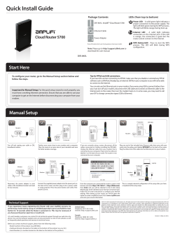


© Copyright 2026