
Document 229
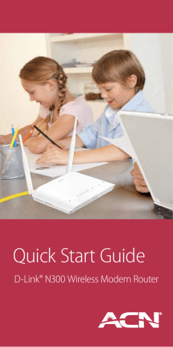
Table of Contents
Table of Contents
General Information..................................................... 4
Package Contents.................................................... 4
Important Safety Instructions.................................... 4
Front Panel View....................................................... 5
Rear Panel View....................................................... 6
Installing the Router..................................................... 7
Installation Diagram..................................................... 9
Configuring Your Computer....................................... 10
Windows® 2000....................................................... 10
Windows® XP.......................................................... 11
Log in to the Router .................................................. 12
Home............................................................................ 13
Wizard.................................................................... 13
ATM PVC Configuration................................ 13
WAN....................................................................... 20
LAN......................................................................... 26
DNS........................................................................ 27
DNS Server Configuration............................. 27
Dynamic DNS......................................................... 28
Logout..................................................................... 29
Advanced Setup......................................................... 30
ADSL...................................................................... 30
ADSL Settings.................................................. 31
D-Link DSL-2540B ADSL2+ 4-Port Router User Manual
ADSL Tone Settings.......................................... 32
Virtual Server.......................................................... 33
NAT—Virtual Servers Setup............................. 33
DMZ........................................................................ 36
SNMP..................................................................... 36
Filter Outbound....................................................... 37
Outgoing IP Filtering Setup............................... 37
Filter Inbound.......................................................... 38
Incoming IP Filtering Setup............................... 38
Bridge Filters.......................................................... 40
MAC Filtering Setup.......................................... 40
Routing................................................................... 42
Routing - Static Route....................................... 42
RIP.......................................................................... 43
Quality of Service................................................... 44
Tools............................................................................ 46
Admin..................................................................... 46
Time........................................................................ 47
Remote Log............................................................ 48
System.................................................................... 50
Save and Reboot.............................................. 50
Backup Settings................................................ 50
Update Settings................................................ 51
Restore Default Settings................................... 51
Firmware........................................................... 52
Test................................................................... 53
Table of Contents
Status........................................................................... 54
Device Info.............................................................. 54
DHCP Clients......................................................... 54
WAN Info................................................................. 55
Route Info............................................................... 55
Log.......................................................................... 56
LAN......................................................................... 56
WAN....................................................................... 57
ADSL...................................................................... 58
ADSL BER Test...................................................... 59
Troubleshooting.......................................................... 61
Networking Basics..................................................... 63
Check your IP address........................................... 63
Statically Assign an IP address.............................. 64
Contacting Technical Support................................... 65
Warranty...................................................................... 66
Registration................................................................. 68
D-Link DSL-2540B ADSL2+ 4-Port Router User Manual
Section 1 - General Information
General Information
The D-Link DSL-2540B is an ADSL2+ router offering the convenience of 4 LAN ports for additional computers. This
user manual provides you with a simple and easy-to-understand format to install and configure your router.
Package Contents
•ADSL2/2+ 4-Port Ethernet Router
•12VDC, 1A DC CEC-compliant switching power adapter
•RJ-11 telephone cable
•RJ-45 Ethernet cable
•Quick Install Guide
•Documentation CD-ROM (QIG + user manual)
Note: Using a power supply with a different voltage rating than the one included with the DSL-2540B will cause damage
and void the warranty for this product.
Important Safety Instructions
•Place your router on a flat surface close to the cables in a location with sufficient ventilation.
•To prevent overheating, do not obstruct the ventilation openings of this equipment.
•Plug this equipment into a surge protector to reduce the risk of damage from power surges and lightning
strikes.
•Operate this equipment only from an electrical outlet with the correct power source as indicated on the
adapter.
•Do not open the cover of this equipment. Opening the cover will void any warranties on the equipment.
•Unplug equipment first before cleaning. A damp cloth can be used to clean the equipment. Do not use
liquid/aerosol cleaners or magnetic/static cleaning devices.
D-Link DSL-2540B ADSL2+ 4-Port Router User Manual
Section 1 - General Information
Front Panel View
DSL LED
A Solid light indicates the DSL is synchronized.
A flashing LED indicates the router is attempting
to synchronize with the DSL provider.
Power LED
A solid green light indicates
the unit is powered up. A red
light indicates a malfunction.
Status LED
A blinking light indicates traffic is
passing through.
D-Link DSL-2540B ADSL2+ 4-Port Router User Manual
Internet LED
A solid green light indicates that the router has an IP
address and is connected to the Internet. A red light
indicates that the router does not have an IP address
or authentication has failed. No light indicates that
an ADSL connection is not present or the router is in
bridge mode.
Local Network LEDs
A solid light indicates a connection to an
Ethernet-enabled computer on ports 1-4.
This LED blinks during data transmission.
Section 1 - General Information
Rear Panel View
ON/OFF
Press this button to turn the
unit on or off.
Power Receptor
Receptor for the supplied power
adapter.
LAN Ports (1-4)
Connect Ethernet devices such as
computers, switches, and hubs.
DSL Line
Connect to an active telephone
line (RJ-11).
Reset
Pressing the Reset button restores the router to
its original factory default settings.
D-Link DSL-2540B ADSL2+ 4-Port Router User Manual
Section 2 - Installing The Router
Installing the Router
Connect the ADSL and Telephone Lines
•Connect an RJ-11 cable between the wall phone jack and the line-end of the splitter (see diagram
below).
•Attach another RJ-11 phone cable to the router-end of the splitter and the ADSL port on the rear panel
of the router.
•The phone-end of the splitter will be connected to the telephone using a third RJ-11 phone cable.
NOTE: See connections on the installation diagram.
Connect the PC to the Router
•To use the Ethernet connection, connect the Ethernet cable from the computer directly to the router.
Connect one end of the Ethernet cable to the port labeled LAN on the back of the router and attach the
other end to the Ethernet port of your computer.
•If your LAN has more than one computer, you can attach one end of an Ethernet cable to a hub or a
switch and the other to the Ethernet port (labeled LAN) on the router. Note that either a crossover or
straight-through Ethernet cable can be used. The router automatically recognizes the type of connection
that is required.
D-Link DSL-2540B ADSL2+ 4-Port Router User Manual
Section 2 - Installing The Router
Connect the Power Adapter
•Complete the process by connecting the supplied 12VAC, 1A power adapter to the POWER connector
on the back of the device and plug the adapter into a wall outlet or power strip. Then turn on and boot up
your PC and any LAN devices, such as hubs or switches, and any computers connected to them.
D-Link DSL-2540B ADSL2+ 4-Port Router User Manual
Section 3 - Installation Diagram
Installation Diagram
D-Link DSL-2540B ADSL2+ 4-Port Router User Manual
Section 4 - Configuring Your Computer
Configuring Your Computer
Prior to accessing the router through the LAN port, note the following necessary configurations:
•Your PC’s TCP/IP address: 192.168.1.x (where “x” is any number between 2 and 254)
•The router’s default IP address: 192.168.1.1
•Subnet mask: 255.255.255.0
Below are the procedures for configuring your computer. Follow the instructions for the operating system that you
are using.
Windows® 2000
These are instructions for configuring your Windows® 2000 operating system. If you are using Windows® XP please
proceed to page 10.
1. In the Windows taskbar, click on the Start button and point to Settings > Control Panel > Network and
Dial-up Connections (in that order).
2. Click on Local Area Connection. When you have the Local Area Connection Status window open, click
on Properties.
3. Listed in the window are the installed network components. If the list includes Internet Protocol (TCP/IP),
then the protocol has already been enabled, and you can skip to Step 10.
4. If Internet Protocol (TCP/IP) does not appear as an installed component, then click on Install.
5. In the Select Network Component Type window, click on protocol and then the Add button.
6. Select Internet Protocol (TCP/IP) from the list and then click on OK.
D-Link DSL-2540B ADSL2+ 4-Port Router User Manual
10
Section 4 - Configuring Your Computer
7. If prompted to restart your computer with the new settings, click OK.
8. After your computer restarts, click on the Network and Dial-up Connections icon again, and right click on
the Local Area Connection icon and then select Properties.
9. In the Local Area Connection Properties dialog box, select Internet Protocol (TCP/IP) and then click on
Properties.
10. In the Internet Protocol (TCP/IP) Properties dialog box, click in the radio button labeled Use the following
IP address and type 192.168.1.x (where “x” is any number between 2 and 254) and 255.255.255.0 in the
IP address field and Subnet Mask field.
11. Click on OK twice to save your changes and then close the Control Panel.
Windows® XP
1. In the Windows taskbar, click on the Start button then go to Control Panel and then click Network
Connections.
2. In the Network Connections window, right click on the Local Area Connection icon and click on
Properties.
3. Listed in the Local Area Connection window are the installed network components. Make sure the box
for Internet Protocol (TCP/IP) is checked and then click on Properties.
4. In the Internet Protocol (TCP/IP) Properties dialog box, click on the radio button labeled Use the following
IP address and type 192.168.1.x (where x is any number between 2 and 254) for the IP address field
and 255.255.255.0 for the Subnet Mask field.
5. Click on OK twice to save your changes and then close the Control Panel.
D-Link DSL-2540B ADSL2+ 4-Port Router User Manual
11
Section 5 - Log In To The Router
Log in to the Router
This section will explain how to log in to your router using the following steps:
1. Launch your web browser.
2. Enter the URL http://192.168.1.1 in the address bar and press Enter.
A login screen like the one below will be displayed after you connect to the user interface.
Note: There are three account types, each
requiring a different username and password.
• The user account provides limited access to certain configurations (username / password: user / user).
• The admin account can perform all functions
(username / password: admin / admin).
• The support account is for ISP technicians for maintenance purposes
(username / password: support / support).
Note: Passwords can be changed at any time.
3. Enter your user name and password, and then click OK to display the user interface.
Note: This manual has been prepared using the admin user name.
D-Link DSL-2540B ADSL2+ 4-Port Router User Manual
12
Section 6 - Home
Home
The home section provides configurations for general use, including a Quick Setup Wizard with steps to quickly set
up your router for Internet connection. Also included in this section are LAN/WAN setup and DNS configuration. The
below sections explains the setup for each.
Wizard
This section will explain how to quickly configure the router if your only intention is to access the Internet.
ATM PVC Configuration
To enable the auto-connect process, click on the box labeled DSL Auto-connect, a process that will automatically
detect the first usable PVC and automatically detect PPPoE, PPPoA, and Bridge Protocol (with DHCP Server available).
To continue, click on the Next button.
D-Link DSL-2540B ADSL2+ 4-Port Router User Manual
13
Section 6 - Home
If you uncheck the DSL Auto-connect box, the resulting screen is seen below. Enter the VPI/VCI as indicated by your
ISP. There is also an option to enable Quality of Service. When you are ready, click Next to continue.
D-Link DSL-2540B ADSL2+ 4-Port Router User Manual
14
Section 6 - Home
Next is the Connection Type screen where you can select the type of network protocol and encapsulation mode over
the ATM PVC that your ISP has instructed you to use. The following is a PPPoA example. Click Next to continue.
D-Link DSL-2540B ADSL2+ 4-Port Router User Manual
15
Section 6 - Home
Enter the PPP username and password given by your ISP. Then decide if you will be using any features such as dial
on demand, PPP IP extension, keep alive and then click on Next.
D-Link DSL-2540B ADSL2+ 4-Port Router User Manual
16
Section 6 - Home
The next step is to configure the Network Address Translation (NAT) settings. For the example, NAT will be enabled.
Leave the remaining fields at their defaults and click Next to continue.
D-Link DSL-2540B ADSL2+ 4-Port Router User Manual
17
Section 6 - Home
In this section, you can configure the DSL Router IP address and Subnet Mask to make the LAN interface correspond
to your LAN’s IP Subnet. If you want the DHCP server to automatically assign IP addresses, then enable the DHCP
server and enter the range of IP addresses that the DHCP server can assign to your computers. Disable the DHCP
server if you would like to manually assign IP addresses. Click Next to continue.
D-Link DSL-2540B ADSL2+ 4-Port Router User Manual
18
Section 6 - Home
After all WAN configurations are complete, the WAN Setup Summary screen displays all WAN settings that you have
made. Check that the settings are correct before clicking on the Save/Reboot button. Clicking on Save/Reboot will
save your settings and restart your router.
D-Link DSL-2540B ADSL2+ 4-Port Router User Manual
19
Section 6 - Home
WAN
Configure the WAN settings as provided by your ISP.
Click on the Add button if you want to add a
new connection for the WAN interface and
to proceed to the ATM PVC Configuration
screen as seen on page 21. The ATM PVC
Configuration screen allows you to configure
an ATM PVC identifier (VPI and VCI) and
select a service category.
D-Link DSL-2540B ADSL2+ 4-Port Router User Manual
20
Section 6 - Home
Note: The Following settings are ISP dependant. For information regarding proper configuration, contact your ISP.
VPI: Virtual Path Identifier. The valid range is 0 to 255.
VCI: Virtual Channel Identifier. The valid range is 32 to 65535.
Service Five classes of traffic are listed:
Category:
UBR Without PCR UBR service is suitable for applications that can
(Unspecified Bit Rate without tolerate variable delays and some cell losses.
Peak Cell Rate): Applications suitable for UBR service include text/
data/image transfer, messaging, distribution, and
retrieval and also for remote terminal applications
such as telecommuting.
UBR With PCR (Unspecified UBR service is suitable for applications that can
Bit Rate with Peak Cell tolerate variable delays and some cell losses. The
Rate): Peak Cell Rate is a determining factor in how often
cells are sent in an effort to minimize lag or jitter
caused by traffic inconsistencies.
CBR (Constant Bit Rate): Used by applications that require a fixed data rate
that is continuously available during the connection
time. It is commonly used for uncompressed audio
and video information such as videoconferencing,
interactive audio (telephony), audio / video distribution
(e.g. television, distance learning, and pay-per-view),
and audio / video retrieval (e.g. video-on-demand and
audio library).
Non Realtime VBR Can be used for data transfers that have critical response-time requirements such as airline reservations,
(Non-Real-time banking transactions, and process monitoring.
Variable Bit Rate):
Realtime VBR (Real-time Used by time-sensitive applications such as real-time video. Rt-VBR service allows the network more flexibility
Variable Bit Rate): than CBR.
Quality of Can be enabled only for UBR without PCR, UBR with PCR, and Non Realtime VPR.
Service:
D-Link DSL-2540B ADSL2+ 4-Port Router User Manual
21
Section 6 - Home
This screen shows the types of network
protocols and encapsulation modes that can
be configured:
•PPP over ATM (PPPoA)
•PPP over Ethernet (PPPoE)
•MAC Encapsulation Routing (MER)
•IP over ATM (IpoA)
•Bridging
If you will be using VLAN tagging, click on the
Enable 802.1q checkbox and then enter the
VLAN ID number. When finished with your
selections, click Next to continue.
Note: These settings are ISP dependant. For
information regarding proper configuration,
contact your ISP.
D-Link DSL-2540B ADSL2+ 4-Port Router User Manual
22
Section 6 - Home
The following screen allows you to enter PPP username and password as well as make any selections regarding your
connection.
Dial on demand: Allows you to manually connect to the
Internet so you are not permanently
connected. Idle timeout timer is
included.
PPP IP extension: Used by some ISP’s. Check with your
ISP to see if it is required.
Keep alive: Keeps you connected to your ISP
even when no activity is present for
a certain period of time.
Use static IP Select if you want to use a non-DHCP
address: issued IP address to connect to the
Internet. If selected, you will be asked
to enter the static IP address.
Note: These settings are ISP dependant. For
information regarding proper configuration, contact
your ISP.
When finished, click Next to proceed to the NAT
Settings screen.
D-Link DSL-2540B ADSL2+ 4-Port Router User Manual
23
Section 6 - Home
This screen allows you to configure the Network Address Translation settings for the router.
Enable NAT: Select enable if you wish to share one WAN IP
address for multiple computers on your LAN.
Enable Firewall: Select if you wish to enable the router’s firewall
for security.
Enable IGMP Select enable if you wish to be able to provide
Multicast: multicasts, mostly used in video streaming.
Enable WAN Select if you wish to use WAN service and then
Service: set the service name.
When finished, click the Next button and the following WAN
summary screen will be displayed. This screen will outline
all WAN settings for review. When satisfied with the settings
click on the Apply button.
D-Link DSL-2540B ADSL2+ 4-Port Router User Manual
24
Section 6 - Home
After you apply the configuration, it
will return to the WAN Setup screen
showing the new configuration. Select
the Finish button to save the changes
and reboot the router.
When the router restarts the DSL
Router Reboot screen will appear
during the reboot process.
D-Link DSL-2540B ADSL2+ 4-Port Router User Manual
25
Section 6 - Home
LAN
You can configure the DSL Router IP address
and Subnet Mask for the LAN interface.
If you will be multicasting (e.g. video streaming)
you can enable IGMP snooping. IGMP snooping
allows the router to efficiently determine where
the multicast traffic came from and where
it is headed. There are two IGMP snooping
options: standard or blocking mode.
If you want the DHCP server to automatically
assign IP addresses, select enable DHCP
server and enter the range of IP addresses that
the DHCP server can assign. Select Disable
DHCP server if you would like to manually
assign IP addresses.
The Save button only saves the LAN
configuration data, but does not apply the
configuration. Select the Save/Reboot button
to save the LAN configuration data, reboot the
router and apply the new configuration.
D-Link DSL-2540B ADSL2+ 4-Port Router User Manual
26
Section 6 - Home
DNS
DNS Server Configuration
Use the DNS Server screen to request automatic
assignment of a DNS or to specify a primary and
secondary DNS.
If you uncheck the Enable Automatic Assigned
DNS checkbox, two additional fields will appear:
primary and secondary DNS server. Enter one
primary and one secondary DNS address in each
field. Click Apply to save the configuration.
D-Link DSL-2540B ADSL2+ 4-Port Router User Manual
27
Section 6 - Home
Dynamic DNS
Dynamic DNS is a service for allowing an Internet domain name to be assigned to a changing IP address. This makes
it possible for other sites on the Internet to establish connections to you without needing to track the IP address
themselves.
Click on Add to set up a dynamic DNS
configuration.
This screen allows you to add a dynamic DNS
address from DynDNS.org or TZO. First select the
DDNS provider (DynDNS.org or TZO) from which
you have obtained a dynamic DNS address. Enter
the hostname and the interface that you are using.
Also enter the username and password assigned
by the DNS service. Click on Apply to save these
configurations.
D-Link DSL-2540B ADSL2+ 4-Port Router User Manual
28
Section 6 - Home
Logout
To log out of the router’s user interface at any time during the setup, click on the Logout button. A confirmation screen
will appear confirming that you really want to log out.
D-Link DSL-2540B ADSL2+ 4-Port Router User Manual
29
Section 7 - Advanced Setup
Advanced Setup
This section of the setup is an advanced version of the quick setup. If you want to make specific configurations to your
router such as creating a virtual server, DMZ, RIP, Quality of Service (QoS), etc., consider going through this advanced
setup for a more comprehensive configuration.
ADSL
The ADSL settings page contains modulation and
capability settings. Consult your ISP to determine the
correct settings. Click Apply if you are finished or click
on Advanced Settings if you want to configure more
advanced settings.
D-Link DSL-2540B ADSL2+ 4-Port Router User Manual
30
Section 7 - Advanced Setup
ADSL Settings
The test mode can be selected from the ADSL Advanced Settings page. Test modes include normal, reverb, medley,
no retrain, and L3. After you make your selection, click on Apply to save these settings first before you go to Tone
Selection.
D-Link DSL-2540B ADSL2+ 4-Port Router User Manual
31
Section 7 - Advanced Setup
ADSL Tone Settings
The frequency band of ADSL is split into 256 separate tones, each spaced 4.3125 kHz apart. Each tone carries separate
data, so the router operates as if 256 separate routers were running in parallel. The tone range is from 0 to 31 for
upstream and from 32 to 255 for downstream. Do not change these settings unless directed by your ISP.
D-Link DSL-2540B ADSL2+ 4-Port Router User Manual
32
Section 7 - Advanced Setup
Virtual Server
If you enable NAT (Network Address Translation), you can configure the Virtual Server, Port Triggering, and DMZ Host.
NAT—Virtual Servers Setup
A virtual server allows you to direct incoming traffic from the WAN side to a specific IP address on the LAN side. This
is useful if you have software that requires communication with the Internet (e.g. peer-to-peer, games, etc.).
This figure shows the Virtual Servers
Setup page that allows you to configure
your virtual server(s). Click on the Add
button to configure a virtual server.
D-Link DSL-2540B ADSL2+ 4-Port Router User Manual
33
Section 7 - Advanced Setup
Select a virtual server from the drop-down
list and then enter the server IP address.
The Server IP Address would normally be
the IP address of the computer on your
network which is using the application or
game.
See Networking Basics in the Appendix
section of this manual to determine your
IP address.
Once you are satisfied with your selection,
click Apply once.
D-Link DSL-2540B ADSL2+ 4-Port Router User Manual
34
Section 7 - Advanced Setup
The following screen appears after you save your selection. To add additional virtual servers, click on the Add button.
If you need to remove any of the server names, select the check box in the remove column and click on the Remove
button.
D-Link DSL-2540B ADSL2+ 4-Port Router User Manual
35
Section 7 - Advanced Setup
DMZ
You can define the IP address of the DMZ Host on this
screen. The DMZ is used to forward all IP packets coming
into the router to a specified IP address. Enter the IP
address and click Apply.
SNMP
SNMP (Simple Network Management Protocol) is a network
protocol that provides a means to monitor the status and
performance of the router, as well as make configuration
changes. It enables a management station to configure,
monitor and receive trap messages from network devices
that are configured for SNMP.
To configure the SNMP agent select Enable, Enter
a Read Community, Set Community, System Name,
Location, Contact, and the IP address of the Trap
Manager. To save the configuration click Apply.
D-Link DSL-2540B ADSL2+ 4-Port Router User Manual
36
Section 7 - Advanced Setup
Filter Outbound
Outgoing IP Filtering Setup
The outgoing filter will block the LAN traffic from
entering the WAN side. Click on the Add button to
create filters.
This next screen will appear when you click Add.
Enter the filter name, source information (from the
LAN side), and destination information (from the
WAN side). Then click Apply to save.
D-Link DSL-2540B ADSL2+ 4-Port Router User Manual
37
Section 7 - Advanced Setup
The following screen will appear when you create
an IP filter. This screen lists the IP filters that were
added from the previous screen. To change your
settings, click on the Add or Remove buttons.
Filter Inbound
Incoming IP Filtering Setup
Incoming IP filter allows specified the WAN traffic
to pass through the firewall. Click the Add button to
add incoming filter settings.
D-Link DSL-2540B ADSL2+ 4-Port Router User Manual
38
Section 7 - Advanced Setup
The Add IP Filter screen will appear when you click
Add. Enter a filter name, protocol, source address
information (from the WAN side) and destination
address information (to the LAN side). Select the
WAN interface and when ready, click Apply to add
the filter.
The following screen appears when you create
an IP filter. The screen lists the IP filters that were
added from the previous screen. To change your
settings, click the Add or Remove buttons.
D-Link DSL-2540B ADSL2+ 4-Port Router User Manual
39
Section 7 - Advanced Setup
Bridge Filters
MAC Filtering Setup
MAC filtering can forward or block traffic by MAC address. You can change the policy or add settings to the MAC filtering
table using the MAC Filtering Setup screen.
D-Link DSL-2540B ADSL2+ 4-Port Router User Manual
40
Section 7 - Advanced Setup
If you click Change Policy, a confirmation dialog
allows you to verify your change. Select Yes to
continue, or No to cancel.
If you want to add an entry to the MAC filtering table,
Select Add from the MAC Filtering Setup screen. The
Add MAC Filter screen should then appear. Select a
Protocol Type, enter the Destination and Source MAC
address, the necessary Frame Direction, and WAN
interface (bridge mode only). Click Apply to save.
After you save the settings, a screen showing the settings will appear. On this screen you will be able to view and
delete MAC filtering rules.
D-Link DSL-2540B ADSL2+ 4-Port Router User Manual
41
Section 7 - Advanced Setup
Routing
Routing - Static Route
The Static Route page can be used to add a routing
table (a maximum of 32 entries can be configured).
To proceed, click Add.
On the Static Route Add page, enter the destination
network address, subnet mask, gateway and select
an available WAN interface. When complete, click
Apply.
D-Link DSL-2540B ADSL2+ 4-Port Router User Manual
42
Section 7 - Advanced Setup
RIP
RIP (Routing Information Protocol) is a process of moving a packet from one node to another by forwarding the packet
to the next router. It determines a route based on the smallest hop count between source and destination routers.
If RIP is enabled, the router operation can be
configured as active or passive. Click Apply
to save any changes.
If RIP is set to active, the router will advertise
its routes (reachability information) to others;
if RIP is set to passive, the router will not
advertise its routes, but will listen and
update its routes based on other routers’
advertisements.
D-Link DSL-2540B ADSL2+ 4-Port Router User Manual
43
Section 7 - Advanced Setup
Quality of Service
QoS (Quality of Service) is a method of identifying, classifying and assigning priorities to traffic that passes through
the router. This ensures that time sensitive data (e.g. video streaming) is given priority over other non-essential data.
You can configure the Quality of Service
to apply different priorities to traffic on the
router. Click Add to view the Add Network
Traffic Class Rule screen.
D-Link DSL-2540B ADSL2+ 4-Port Router User Manual
44
Section 7 - Advanced Setup
This screen allows you to add a network traffic class
rule. A rule consists of a traffic class name and at least
one condition. All configured conditions must first be
met before the rule takes effect. Click Apply to save
any changes.
D-Link DSL-2540B ADSL2+ 4-Port Router User Manual
45
Section 8 - Tools
Tools
The tools section contains various administrator functions to maintain your router. Sections include the following:
Admin, Time, Remote Log, System, Firmware, and Test.
•Admin: Allows you to change the password for the various user names available
•Time: Allows you to set the router’s time
•Remote Log: Allows you to view logs of the router’s activities
•System: Allows you to perform functions such as save/reboot, backup, update settings, and restore
default settings
•Firmware: Allows you to upgrade your router with new available firmware versions
•Test: Allows you to view test information for your Internet connection
Admin
There are three usernames and passwords (admin,
support, and user) that can be used to control your
router. The passwords for these usernames can be
changed on the Admin screen. Select the Username,
enter the Old Password, enter a New Password, and
then confirm the new password. When you are ready,
click Apply at the bottom of the page.
D-Link DSL-2540B ADSL2+ 4-Port Router User Manual
46
Section 8 - Tools
Time
The Time Settings page allows you to automatically synchronize your time with a time server on the Internet.
To set the router’s time, click on the automatically
synchronize with Internet time servers checkbox.
Addional time settings will appear below the
checkbox.
Select from the list of NTP (Network Time Protocol) time
servers. Then select the time zone that you are in and
click Apply to save.
D-Link DSL-2540B ADSL2+ 4-Port Router User Manual
47
Section 8 - Tools
Remote Log
The System Log screen allows you to view the system log and configure the system log options.
To view the system log, click on the View System Log
button.
Note: When you click on the View System Log button,
the System Log screen is located under the Status
section (see screen on right). To return to the previous
screen to configure system log, remember to click on
the Tools tab (located on top row) first and then click
on Remotelog.
The System Log screen shows the date/time of the log,
the facility that was logged, the severity level and the log
message. Click on Refresh to view any new information
that has been logged.
System log when log is disabled.
If the log is enabled, the system will log selected events
including Emergency, Alert, Critical, Error, Warning,
Notice, Informational, and Debugging. All events above
or equal to the selected log level will be logged and
displayed.
System log when log is enabled.
D-Link DSL-2540B ADSL2+ 4-Port Router User Manual
48
Section 8 - Tools
To configure the system log, click the Configure
System Log button.
From the configuration screen, set the log to
Enable, select the Log Level, Display Level and
Mode. If the selected mode is “Remote” or “Both”,
events will be sent to a specified IP address and
UDP port of a remote system log server. If the
selected mode is “Local” or “Both”, events will be
recorded and viewed locally. Select the desired
values and click Apply to save the system log
options.
D-Link DSL-2540B ADSL2+ 4-Port Router User Manual
49
Section 8 - Tools
System
The system section includes several tools on one page, including save and reboot, backup settings, update settings,
and restore default settings.
Save and Reboot
The Save/Reboot button, when clicked, will save all configuration changes made on the router and restart the device.
All new configuration settings will take effect when the router starts up again.
Backup Settings
The Backup Settings button allows you to save your router configuration to a file on your computer so that it may be
accessed again later. This feature is useful if you have changed the configuration on the router, but would like to revert
to a previous configuration.
To save your current configuration, click the Backup
Settings button. The following pop-up screen will
appear with a prompt to open or save the file to your
computer.
D-Link DSL-2540B ADSL2+ 4-Port Router User Manual
50
Section 8 - Tools
Update Settings
To load a previously saved configuration file onto your
router, click Browse, select the file on your computer
and then click on Update Settings.
The router will restore settings and reboot to activate
the restored settings.
Restore Default Settings
Restore Default Settings will delete all current settings and restore the router to factory default settings. Click on the
Restore Default Settings button to proceed. The following confirmation dialog will appear confirming your decision to
restore default settings. Click on OK to continue.
D-Link DSL-2540B ADSL2+ 4-Port Router User Manual
51
Section 8 - Tools
Firmware
If your ISP releases new software for this router, follow these steps to perform an upgrade.
1. Obtain an updated software image file (firmware) from your ISP.
2. Enter the path of the image file location or click the Browse button to locate the image file.
3. Click the Update Software button once to upload the new image file.
D-Link DSL-2540B ADSL2+ 4-Port Router User Manual
52
Section 8 - Tools
Test
The diagnostics screen allows you to run diagnostic tests to check your DSL connection. The results will show test
results of three connections:
•Connection to your local network
•Connection to your DSL service provider
•Connection to your Internet service
provider
There are three buttons at the bottom of the
page:
•Next Connection (appears only if
you have created more than one
connection)
•Test
•Test with OAM F4
D-Link DSL-2540B ADSL2+ 4-Port Router User Manual
53
Section 9 - Status
Status
The status section allows you to view general and status information for your router’s connection.
Device Info
The Device Info page shows details of the router such
as the version of the software, bootloader, LAN IP
address, etc. It also displays the current status of your
DSL connection.
DHCP Clients
Access the DHCP Leases screen by clicking DHCP
under Status. This shows the computers, identified by
the hostname and MAC address, that have acquired
IP addresses by the DHCP server. The table will also
show the time the DHCP lease will expire.
D-Link DSL-2540B ADSL2+ 4-Port Router User Manual
54
Section 9 - Status
WAN Info
The WAN Info screen displays WAN connections
previously set up in the Home section. There is an extra
“Status” column used for connection status information,
displaying either ADSL Link Down or ADSL Link Up.
Route Info
The Route Info section displays route information
showing the IP addresses of the destination, gateway,
and subnet mask as well as other route information.
D-Link DSL-2540B ADSL2+ 4-Port Router User Manual
55
Section 9 - Status
Log
This is the same screen as seen in the Remotelog
section under tools.
LAN
The LAN section shows received and transmitted packet information for the Ethernet interface. Click on Reset Statistics
to renew the information.
D-Link DSL-2540B ADSL2+ 4-Port Router User Manual
56
Section 9 - Status
WAN
The WAN section shows received and transmitted packet information for the WAN connections that you have set up.
Click on Reset Statistics to renew the information.
D-Link DSL-2540B ADSL2+ 4-Port Router User Manual
57
Section 9 - Status
ADSL
Information contained in the ADSL screen is useful for troubleshooting and diagnosing connection problems.
D-Link DSL-2540B ADSL2+ 4-Port Router User Manual
58
Section 9 - Status
ADSL BER Test
A Bit Error Rate Test (BER Test) is a test that reflects the ratio of error bits to the total number transmitted.
If you click on the ADSL BER Test button at the bottom
of the ADSL Statistics page, the following pop-up screen
will appear allowing you to set the tested time and to
begin the test. Click Start to begin the test.
When you start the ADSL BER Test, the following
progress window will display the connection speed as
well as the length of time that the test will run for. At
any time during the test, click on the Stop button to
terminate the test.
D-Link DSL-2540B ADSL2+ 4-Port Router User Manual
59
Section 9 - Status
When the test is complete, the following window will
display the test results showing the test time, total
transferred bits, total error bits and error ratio. Click Exit
to close the window.
D-Link DSL-2540B ADSL2+ 4-Port Router User Manual
60
Troubleshooting
This chapter provides solutions to problems that can occur during the installation and operation of the DSL-2540B.
Read the following descriptions if you are having problems. (The examples below are illustrated in Windows® XP. If you
have a different operating system, the screenshots on your computer will look similar to the following examples.)
1. Why can’t I access the web-based configuration utility?
When entering the IP address of the D-Link router (192.168.1.1 for example), you are not connecting to a website on
the Internet or have to be connected to the Internet. The device has the utility built-in to a ROM chip in the device itself.
Your computer must be on the same IP subnet to connect to the web-based utility.
• Make sure you have an updated Java-enabled web browser. We recommend the following:
• Internet Explorer 6.0 or higher
• Netscape 8 or higher
• Mozilla 1.7.12 (5.0) or higher
• Opera 8.5 or higher
• Safari 1.2 or higher (with Java 1.3.1 or higher)
• Camino 0.8.4 or higher
• Firefox 1.5 or higher
• Verify physical connectivity by checking for solid link lights on the device. If you do not get a solid link light, try using
a different cable or connect to a different port on the device if possible. If the computer is turned off, the link light may
not be on.
• Disable any Internet security software running on the computer. Software firewalls such as Zone Alarm, Black Ice,
Sygate, Norton Personal Firewall, and Windows® XP firewall may block access to the configuration pages. Check the
help files included with your firewall software for more information on disabling or configuring it.
D-Link DSL-2540B ADSL2+ 4-Port Router User Manual
61
• Configure your Internet settings:
• Go to Start > Settings > Control Panel. Double-click the Internet Options Icon. From the Security tab,
click the button to restore the settings to their defaults.
• Click the Connection tab and set the dial-up option to Never Dial a Connection. Click the LAN Settings
button. Make sure nothing is checked. Click OK.
• Go to the Advanced tab and click the button to restore these settings to their defaults. Click OK three
times.
• Close your web browser (if open) and open it.
• Access the web management. Open your web browser and enter the IP address of your D-Link router in the
address bar. This should open the login page for your the web management.
• If you still cannot access the configuration, unplug the power to the router for 10 seconds and plug back in. Wait
about 30 seconds and try accessing the configuration. If you have multiple computers, try connecting using a
different computer.
2. What can I do if I forgot my password?
If you forgot your password, you must reset your router. Unfortunately this process will change all your settings back
to the factory defaults.
To reset the router, locate the reset button (hole) on the rear panel of the unit. With the router powered on, use a
paperclip to hold the button down for 10 seconds. Release the button and the router will go through its reboot process.
Wait about 30 seconds to access the router. For information about logging into the router see page 12.
D-Link DSL-2540B ADSL2+ 4-Port Router User Manual
62
Appendix A - Networking Basics
Networking Basics
Check your IP address
After you install your new D-Link adapter, by default, the TCP/IP settings should be set to obtain an IP address from a
DHCP server (i.e. wireless router) automatically. To verify your IP address, please follow the steps below.
Click on Start > Run. In the run box type cmd and click OK.
At the prompt, type ipconfig and press Enter.
This will display the IP address, subnet mask, and
the default gateway of your adapter.
If the address is 0.0.0.0, check your adapter
installation, security settings, and the settings
on your router. Some firewall software programs
may block a DHCP request on newly installed
adapters.
If you are connecting to a wireless network at a hotspot (e.g. hotel, coffee shop, airport), please contact an employee
or administrator to verify their wireless network settings.
D-Link DSL-2540B ADSL2+ 4-Port Router User Manual
63
Appendix A - Networking Basics
Statically Assign an IP address
If you are not using a DHCP capable gateway/router, or you need to assign a static IP address, please follow the
steps below:
Step 1
Windows® XP - Click on Start > Control Panel > Network Connections.
Windows® 2000 - From the desktop, right-click My Network Places > Properties.
Step 2
Right-click on the Local Area Connection which represents your D-Link network adapter and select Properties.
Step 3
Highlight Internet Protocol (TCP/IP) and click Properties.
Step 4
Click Use the following IP address and enter an IP address that is on the same subnet as your network or the LAN
IP address on your router.
Example: If the router´s LAN IP address is 192.168.0.1, make your IP address
192.168.0.X where X is a number between 2 and 99. Make sure that the number
you choose is not in use on the network. Set Default Gateway the same as the LAN
IP address of your router (192.168.0.1).
Set Primary DNS the same as the LAN IP address of your router (192.168.0.1). The
Secondary DNS is not needed or you may enter a DNS server from your ISP.
Step 5
Click OK twice to save your settings.
D-Link DSL-2540B ADSL2+ 4-Port Router User Manual
64
Appendix B - Contacting Technical Support
Contacting Technical Support
U.S. and Canadian customers can contact D-Link technical support through our web site or by phone.
Before you contact technical support, please have the following ready:
• Model number of the product (e.g. DSL-2540B)
• Hardware Revision (located on the label on the bottom of the router (e.g. rev A1))
• Serial Number (s/n number located on the label on the bottom of the router).
You can find software updates and user documentation on the D-Link website as well as frequently asked questions
and answers to technical issues.
For customers within the United States:
For customers within Canada:
Phone Support:
(877) 453-5465
Internet Support:
http://support.dlink.com
Phone Support:
(800) 361-5265
Internet Support:
http://support.dlink.ca
D-Link DSL-2540B ADSL2+ 4-Port Router User Manual
65
Appendix C - Warranty
Warranty
Subject to the terms and conditions set forth herein, D-Link Systems, Inc. (“D-Link”) provides this Limited Warranty:
•
Only to the person or entity that originally purchased the product from D-Link or its authorized reseller or distributor, and
•
Only for products purchased and delivered within the fifty states of the United States, the District of Columbia, U.S. Possessions or Protectorates, U.S. Military Installations, or addresses with an APO
or FPO.
Limited Warranty: D-Link warrants that the hardware portion of the D-Link product described below (“Hardware”) will be free from material defects in workmanship and materials under normal use from the
date of original retail purchase of the product, for the period set forth below (“Warranty Period”), except as otherwise stated herein.
•
Hardware (excluding power supplies and fans): One (1) year
•
Power supplies and fans: One (1) year
•
Spare parts and spare kits: Ninety (90) days
The customer's sole and exclusive remedy and the entire liability of D-Link and its suppliers under this Limited Warranty will be, at D-Link’s option, to repair or replace the defective Hardware during the
Warranty Period at no charge to the original owner or to refund the actual purchase price paid. Any repair or replacement will be rendered by D-Link at an Authorized D-Link Service Office. The replacement
hardware need not be new or have an identical make, model or part. D-Link may, at its option, replace the defective Hardware or any part thereof with any reconditioned product that D-Link reasonably
determines is substantially equivalent (or superior) in all material respects to the defective Hardware. Repaired or replacement hardware will be warranted for the remainder of the original Warranty Period
or ninety (90) days, whichever is longer, and is subject to the same limitations and exclusions. If a material defect is incapable of correction, or if D-Link determines that it is not practical to repair or replace
the defective Hardware, the actual price paid by the original purchaser for the defective Hardware will be refunded by D-Link upon return to D-Link of the defective Hardware. All Hardware or part thereof
that is replaced by D-Link, or for which the purchase price is refunded, shall become the property of D-Link upon replacement or refund.
Limited Software Warranty: D-Link warrants that the software portion of the product (“Software”) will substantially conform to D-Link’s then current functional specifications for the Software, as set forth
in the applicable documentation, from the date of original retail purchase of the Software for a period of ninety (90) days (“Software Warranty Period”), provided that the Software is properly installed on
approved hardware and operated as contemplated in its documentation. D-Link further warrants that, during the Software Warranty Period, the magnetic media on which D-Link delivers the Software will be
free of physical defects. The customer’s sole and exclusive remedy and the entire liability of D-Link and its suppliers under this Limited Warranty will be, at D-Link’s option, to replace the non-conforming
Software (or defective media) with software that substantially conforms to D-Link’s functional specifications for the Software or to refund the portion of the actual purchase price paid that is attributable to the
Software. Except as otherwise agreed by D-Link in writing, the replacement Software is provided only to the original licensee, and is subject to the terms and conditions of the license granted by D-Link for
the Software. Replacement Software will be warranted for the remainder of the original Warranty Period and is subject to the same limitations and exclusions. If a material non-conformance is incapable of
correction, or if D-Link determines in its sole discretion that it is not practical to replace the non-conforming Software, the price paid by the original licensee for the non-conforming Software will be refunded
by D-Link; provided that the non-conforming Software (and all copies thereof) is first returned to D-Link. The license granted respecting any Software for which a refund is given automatically terminates.
Non-Applicability of Warranty: The Limited Warranty provided hereunder for Hardware and Software portions of D-Link’s products will not be applied to and does not cover any refurbished product and any
product purchased through the inventory clearance or liquidation sale or other sales in which D-Link, the sellers, or the liquidators expressly disclaim their warranty obligation pertaining to the product and in
that case, the product is being sold “As-Is” without any warranty whatsoever including, without limitation, the Limited Warranty as described herein, notwithstanding anything stated herein to the contrary.
Submitting A Claim: The customer shall return the product to the original purchase point based on its return policy. In case the return policy period has expired and the product is within warranty, the
customer shall submit a claim to D-Link as outlined below:
•
The customer must submit with the product as part of the claim a written description of the Hardware defect or Software nonconformance in sufficient detail to allow D-Link to confirm the same, along
with proof of purchase of the product (such as a copy of the dated purchase invoice for the product) if the product is not registered.
•
The customer must obtain a Case ID Number from D-Link Technical Support at 1-877-453-5465, who will attempt to assist the customer in resolving any suspected defects with the product. If the product
is considered defective, the customer must obtain a Return Material Authorization (“RMA”) number by completing the RMA form and entering the assigned Case ID Number at https://rma.dlink.com/.
•
After an RMA number is issued, the defective product must be packaged securely in the original or other suitable shipping package to ensure that it will not be damaged in transit, and the RMA number
must be prominently marked on the outside of the package. Do not include any manuals or accessories in the shipping package. D-Link will only replace the defective portion of the product and will
not ship back any accessories.
•
The customer is responsible for all in-bound shipping charges to D-Link. No Cash on Delivery (“COD”) is allowed. Products sent COD will either be rejected by D-Link or become the property of D-Link.
Products shall be fully insured by the customer and shipped to D-Link Systems, Inc., 17595 Mt. Herrmann, Fountain Valley, CA 92708. D-Link will not be held responsible for any packages that are
lost in transit to D-Link. The repaired or replaced packages will be shipped to the customer via UPS Ground or any common carrier selected by D-Link. Return shipping charges shall be prepaid by
D-Link if you use an address in the United States, otherwise we will ship the product to you freight collect. Expedited shipping is available upon request and provided shipping charges are prepaid by
the customer.
D-Link DSL-2540B ADSL2+ 4-Port Router User Manual
66
Appendix C - Warranty
D-Link may reject or return any product that is not packaged and shipped in strict compliance with the foregoing requirements, or for which an RMA number is not visible from the outside of the package. The
product owner agrees to pay D-Link’s reasonable handling and return shipping charges for any product that is not packaged and shipped in accordance with the foregoing requirements, or that is determined
by D-Link not to be defective or non-conforming.
What Is Not Covered: The Limited Warranty provided herein by D-Link does not cover: Products that, in D-Link’s judgment, have been subjected to abuse, accident, alteration, modification, tampering,
negligence, misuse, faulty installation, lack of reasonable care, repair or service in any way that is not contemplated in the documentation for the product, or if the model or serial number has been altered,
tampered with, defaced or removed; Initial installation, installation and removal of the product for repair, and shipping costs; Operational adjustments covered in the operating manual for the product, and
normal maintenance; Damage that occurs in shipment, due to act of God, failures due to power surge, and cosmetic damage; Any hardware, software, firmware or other products or services provided by
anyone other than D-Link; and Products that have been purchased from inventory clearance or liquidation sales or other sales in which D-Link, the sellers, or the liquidators expressly disclaim their warranty
obligation pertaining to the product. While necessary maintenance or repairs on your Product can be performed by any company, we recommend that you use only an Authorized D-Link Service Office.
Improper or incorrectly performed maintenance or repair voids this Limited Warranty.
Disclaimer of Other Warranties: EXCEPT FOR THE LIMITED WARRANTY SPECIFIED HEREIN, THE PRODUCT IS PROVIDED “AS-IS” WITHOUT ANY WARRANTY OF ANY KIND WHATSOEVER
INCLUDING, WITHOUT LIMITATION, ANY WARRANTY OF MERCHANTABILITY, FITNESS FOR A PARTICULAR PURPOSE AND NON-INFRINGEMENT. IF ANY IMPLIED WARRANTY CANNOT BE
DISCLAIMED IN ANY TERRITORY WHERE A PRODUCT IS SOLD, THE DURATION OF SUCH IMPLIED WARRANTY SHALL BE LIMITED TO THE DURATION OF THE APPLICABLE WARRANTY PERIOD
SET FORTH ABOVE. EXCEPT AS EXPRESSLY COVERED UNDER THE LIMITED WARRANTY PROVIDED HEREIN, THE ENTIRE RISK AS TO THE QUALITY, SELECTION AND PERFORMANCE OF
THE PRODUCT IS WITH THE PURCHASER OF THE PRODUCT.
Limitation of Liability: TO THE MAXIMUM EXTENT PERMITTED BY LAW, D-LINK IS NOT LIABLE UNDER ANY CONTRACT, NEGLIGENCE, STRICT LIABILITY OR OTHER LEGAL OR EQUITABLE
THEORY FOR ANY LOSS OF USE OF THE PRODUCT, INCONVENIENCE OR DAMAGES OF ANY CHARACTER, WHETHER DIRECT, SPECIAL, INCIDENTAL OR CONSEQUENTIAL (INCLUDING,
BUT NOT LIMITED TO, DAMAGES FOR LOSS OF GOODWILL, LOSS OF REVENUE OR PROFIT, WORK STOPPAGE, COMPUTER FAILURE OR MALFUNCTION, FAILURE OF OTHER EQUIPMENT
OR COMPUTER PROGRAMS TO WHICH D-LINK’S PRODUCT IS CONNECTED WITH, LOSS OF INFORMATION OR DATA CONTAINED IN, STORED ON, OR INTEGRATED WITH ANY PRODUCT
RETURNED TO D-LINK FOR WARRANTY SERVICE) RESULTING FROM THE USE OF THE PRODUCT, RELATING TO WARRANTY SERVICE, OR ARISING OUT OF ANY BREACH OF THIS LIMITED
WARRANTY, EVEN IF D-LINK HAS BEEN ADVISED OF THE POSSIBILITY OF SUCH DAMAGES. THE SOLE REMEDY FOR A BREACH OF THE FOREGOING LIMITED WARRANTY IS REPAIR,
REPLACEMENT OR REFUND OF THE DEFECTIVE OR NON-CONFORMING PRODUCT. THE MAXIMUM LIABILITY OF D-LINK UNDER THIS WARRANTY IS LIMITED TO THE PURCHASE PRICE
OF THE PRODUCT COVERED BY THE WARRANTY. THE FOREGOING EXPRESS WRITTEN WARRANTIES AND REMEDIES ARE EXCLUSIVE AND ARE IN LIEU OF ANY OTHER WARRANTIES OR
REMEDIES, EXPRESS, IMPLIED OR STATUTORY.
Governing Law: This Limited Warranty shall be governed by the laws of the State of California. Some states do not allow exclusion or limitation of incidental or consequential damages, or limitations on
how long an implied warranty lasts, so the foregoing limitations and exclusions may not apply. This Limited Warranty provides specific legal rights and you may also have other rights which vary from state
to state.
Trademarks: D-Link is a registered trademark of D-Link Systems, Inc. Other trademarks or registered trademarks are the property of their respective owners.
Copyright Statement: No part of this publication or documentation accompanying this product may be reproduced in any form or by any means or used to make any derivative such as translation,
transformation, or adaptation without permission from D-Link Corporation/D-Link Systems, Inc., as stipulated by the United States Copyright Act of 1976 and any amendments thereto. Contents are subject
to change without prior notice. Copyright 2006 by D-Link Corporation/D-Link Systems, Inc. All rights reserved.
CE Mark Warning: This is a Class B product. In a domestic environment, this product may cause radio interference, in which case the user may be required to take adequate measures.
FCC Statement: This equipment has been tested and found to comply with the limits for a Class B digital device, pursuant to part 15 of the FCC Rules. These limits are designed to provide reasonable
protection against harmful interference in a residential installation. This equipment generates, uses, and can radiate radio frequency energy and, if not installed and used in accordance with the instructions,
may cause harmful interference to radio communication. However, there is no guarantee that interference will not occur in a particular installation. If this equipment does cause harmful interference to radio
or television reception, which can be determined by turning the equipment off and on, the user is encouraged to try to correct the interference by one or more of the following measures:
•
Reorient or relocate the receiving antenna.
•
Increase the separation between the equipment and receiver.
•
Connect the equipment into an outlet on a circuit different from that to which the receiver is connected.
•
Consult the dealer or an experienced radio/TV technician for help.
For detailed warranty information applicable to products purchased outside the United States, please contact the corresponding local D-Link office.
D-Link DSL-2540B ADSL2+ 4-Port Router User Manual
67
Appendix D - Registration
Registration
Product registration is entirely voluntary and failure to complete or return this form will not diminish your warranty
rights.
Version 1.0
September 26, 2006
D-Link DSL-2540B ADSL2+ 4-Port Router User Manual
68


© Copyright 2026