
Document 2432
-Bruce Wallace Biotechnology Lab Program ••• STUDENT GUIDE Third Edition -Bruce Wallace Biotechnology Program Preface The significance of the science you are about to do is sometimes taken for granted as the protocols have been worked and reworked so that there is a high probability that you will succeed at producing the desired molecular product. The work that you are about to do is based on Nobel Prize winning science. Werner Arbor, Daniel Nathans and Hamilton Smith received the Nobel Prize for their work with restriction enzymes. Stanley Cohen, Paul Berg and Herb Boyer received the Prize for making the first recombinant DNA molecule. The recombinant DNA molecule that you are about to use extends beyond their work as it uses a gene from a eukaryote rather than prokaryotic organism. As recently as 1993, Kary Mullis received the Nobel Prize for his discovery of the Polymerase Chain Reaction, some elegant chemistry that you will be using in Laboratory eight. So the science you will be covering over the next few weeks is significant and will continue to play an important role in the development of biotechnology and medicine. Your teacher deserves a great deal of credit for making this laboratory experience possible. Although AMGEN provides the equipment and the supplies needed to implement the labs, your teacher has provided many hours of preparation time, often involving weekends and evenings, to make the experience possible. If you’ve enjoyed this laboratory experience, please remember to thank your teacher for making the experience a reality. This educational outreach program is largely the result of the efforts of Dr. Bruce Wallace, an Amgen scientist, who strongly believed the biotechnology industry had a responsibility to contribute to science education of our society. Before Dr. Wallace’s untimely passing, he was able to see his educational outreach program grow and evolve into the adventure of discovery upon which you are about to begin. Should you have any questions about these laboratories, please feel to e-mail me at the address below. Martin Ikkanda Professor of Biology Los Angeles Pierce College [email protected] 7.22.04 -Bruce Wallace Biotechnology Program TABLE OF CONTENTS Subject Pages Lab 1 An Introduction to Microvolumetrics and Pipetting.............................................1.1 – 1.6 Lab 2 Restriction Analysis of pDRK and pGRN ............................................................2.1 – 2.4 Lab 2a rpGLO Restriction Digest: An Introduction to Plasmids....................................2a.1-2a.5 and Restriction Enzymes Lab 3 Ligation of pDRK/pGRN Restriction Fragments Producing................................3.1 – 3.5 Lab 4 Confirmation of Restriction and Ligation Using Agarose-...................................4.1 – 4.4 Gel Electrophoresis Lab 4a Confirmation of rpGLO Restriction Digest .........................................................4a.1-4a.5 Lab 5 Transformation of Escherichia coli with a Recombinant .....................................5.1 – 5.8 Plasmid Lab 5a Transforming Escherichia coli (HB101) with rpGLO...................................... 5a.1 – 5a.5 Lab 6 Preparing an Overnight Culture of E. coli ............................................................6.1 – 6.4 Lab 6a Preparing an Overnight Culture of E. coli ........................................................ 6a.1 – 6a.4 Lab 7 Purification of GFP from an Overnight Culture ...................................................7.1 – 7.7 Lab 8 Genomic DNA Extraction From Buccal Epithelial Cells and ..............................8.1 – 8.5 Amplification of the tPA Locus Using the Polymerase Chain Reaction Appendix I - Glossary..................................................................................................... AI.1 – AI.8 7.22.04 -Bruce Wallace Biotechnology Program Laboratory 1 An Introduction to Microvolumetrics and Pipetting INTRODUCTION The purpose of this laboratory is to provide you with a hands-on experience using some of the important tools and techniques commonly used in molecular biology and introduce you to some of the volumetric measurements that are most often used in this field of science. The laboratory will provide you with an opportunity to practice some of the skills you will need to build a recombinant DNA molecule. The instruments and supplies that you will be using over the next few weeks are identical to the ones that are used in research laboratories. While the theoretical foundations upon which biotechnology and DNA sciences have been built extend back to the early 1900’s, most of the laboratory techniques utilized are relatively recent. And though the techniques you will be learning over the next few weeks have become routine in modern research laboratories, few high school and college students have an opportunity to do such sophisticated molecular biology. If and when you take a chemistry class, one of the things you will quickly notice is the differences the quantities of reagents and chemicals that you use. In a typical chemistry lab, volumes are measured in large graduated cylinders. Solutions are often measured in 50, 100, 200 milliliters (mL) volumes. Weights of solids are generally expressed in grams (g). In the molecular biology lab, volumes are frequently measured in microliters (µL); 1 µL is equal to 0.001 mL. Weights are often expressed in terms of micrograms (µg) or nanograms (ng); 1 µg is equal to 0.000001 gram and 1 ng is equal to 0.000000001 gram. You might be wondering why molecular biologists use such small volumes and amounts of materials. The reason is related to the cost of these materials and the difficulty involved with obtaining them. For example, you will be given some specially engineered plasmids (DNA) in the next laboratory. If this DNA were sold “by the pound,” it would cost around $3,600,000,000 per pound. So don’t be surprised if we only give you a tiny amount of these DNA molecules. The reason why these chemicals are so expensive is related to the difficulty in preparing them in pure form. Many of these chemicals are produced within living organisms, like bacteria, and have to be purified and separated from all of the other thousands of substances in the cell. Molecular biology, however, really requires this level of purity and precision. As you do this lab work, keep in mind that you are doing real-world molecular biology. MATERIALS 07/22/04 Reagents Equipment and supplies Solution 1 Solution 2 Solution 3 Distilled H2O (dH2O) 1% Agarose gel (pre-made) 0.5x TBE (or 1x SB) 1.5 mL microfuge tubes P-20 micropipettor (2-20 µL) Disposable pipette tips Permanent marker Electrophoresis equipment Power supply Plastic microfuge tube rack 1.1 Martin Ikkanda -Bruce Wallace Biotechnology Program Laboratory 1 METHODS The Digital Micropipettor Molecular biology protocols require the use of adjustable micropipettors. Micropipettors are used to dispense different volumes of liquids. While researchers will have several kinds of micropipettors at their lab bench, these laboratories have been designed to utilize a P-20. The P-20 is engineered to dispense liquid volumes between 2 and 20 µL. Plunger button Although there are times when your teacher will have you set Tip ejector the P-20 to dispense 1 µL. This is a high quality, precision instrument and it is essential that you learn to use it properly. Display window Please read and follow these precautions: • Do not set the adjustment below 2 µL or above 20 µL unless instructed to do so by your teacher. If you are using the Amgen kit with the P-10 micropipettors, do not set the adjustments below 1 µL or above 10 µL. • Do not use the micropipettor without the proper disposable tip. This will contaminate the pipette barrel. • Do not lay down a micropipettor with fluid in the tip or hold it with the tip pointed upward. If the disposable tip is not firmly seated onto the barrel, fluid could leak back into the pipettor. • Avoid letting the plunger “snap” back when withdrawing or ejecting fluid; it will eventually destroy the piston. Barrel 1. Find the display window on the handle of the micropipette and note its setting. Turn the knurled knob, in the handle, clockwise to decrease the volume or counterclockwise to increase the volume. This changes the distance the plunger will travel. The figures below represent some pipette settings and the volumes of liquid dispensed. 2 1 0 0 0 2 5 2 0 4 5 0 20.0 µL 07/22/04 12.4 µL 5.5 µL 1.2 2.0 µL Martin Ikkanda -Bruce Wallace Biotechnology Program Laboratory 1 2. Place a disposable tip onto the end of the pipettor barrel. Using your thumb and index finger in a twisting motion, check to see that the tip if firmly seated onto the barrel. Avoid touching the pointed end, as this may contaminate the tip. Remember that you must have a tip in place when using the pipettor. 3. Place your thumb on the button that activates the plunger. Push down on this button with your thumb and notice that it has a “stop” position. If you exert a little more pressure with your thumb, you can push the button of the plunger to a second stop. The second stop pushes a small volume of air into the tip to eject the solution. • When aspirating (drawing-up) a solution, push the plunger to the first stop and lower the pipette tip below the level of the solution that you are sampling. You should be holding the tube, containing the solution in your hand, about at eye-level. It’s important to actually see the solution enter the pipette tip. • Slowly release the plunger and allow the liquid to move into the pipette tip. Be certain that you’re not aspirating air into the tip. • When dispensing (pushing out) the liquid, place the pipette tip into the tube that will receive the solution. Position the tip so that it touches the side and near the bottom of the tube. Slowly push down on the plunger to the first stop and then to the second stop. Keep your thumb on the plunger and remove the tip from the tube into which you’re dispensing the liquid. This will avoid re-aspirating the liquid into the pipette tip. Be certain that you see the solution leaving the tip. • Remove the tip by ejecting it into a waste container; there is an eject button on the pipettor. If you’re dispensing the same reagent into separate tubes and there is no danger of cross contamination, you can use the same tip several times. To avoid contamination, it is good practice to deposit each reagent on to the sidewall, near the bottom of the microfuge tube without touching any of the other reagents. This technique allows you to use the same tip to dispense a reagent into several tubes that contain a different reagent. • When dispensing a new reagent, always use a fresh tip to avoid contamination. Pipetting exercise 1. Use a permanent marker to label three reaction tubes A, B, and C. 2. The table below summarizes the contents of each tube but follow the directions that begin with step 3 to set-up the mixture. Tube dH2O A 2 µL B 2 µL C 2 µL 07/22/04 Solution 1 4 µL ⎯ ⎯ Solution 2 Solution 3 4 µL ⎯ 8 µL ⎯ 8 µL ⎯ 1.3 Total volume 10 µL 10 µL 10 µL Martin Ikkanda -Bruce Wallace Biotechnology Program Laboratory 1 3. Set the P-20 micropipette to 2 µL and dispense dH2O into tubes A, B and C. 4. Eject the tip into the plastic waste container and replace with a fresh tip. 5. Place 4 µL of solution 1 into tube A. 6. Eject the tip into the plastic waste container and replace with a fresh tip. 7. Use a fresh tip and dispense 4 µL of solution 3 into tube A. 8. Use a fresh tip and dispense 8 µL of solution 2 into tube B. 9. Use a fresh tip and dispense 8 µL of solution 3 into tube C. 10. Save all three tubes for the next part of the lab. Checking the accuracy and consistency of pipetting 1. Tubes A, B and C should each contain 10 µL of solution. 2. Set your P-20 micropipette to 10 µL and place a fresh tip on to the barrel. 3. Carefully check the volume of each of microfuge tube. There should be 10 µL in each of these tubes. 4. Save tubes A, B and C for the next part of the lab. Using Gel Electrophoresis to Separate Molecules Gel electrophoresis is a method that uses an electrical current and a gel matrix (meshwork) to separate molecules like DNA and proteins. The molecules that are being separated are either negatively charged or are made to be negatively charged. Using an electrical current, the charged molecules are then forced through a meshwork of material that will sort out the molecules according to their sizes, although molecular shape and degree of negativity will influence movement through the gel. Because the molecules are negatively charged, they will migrate through the gel towards the positive (red) electrode. The more negatively charged, the faster the molecule will migrate. In this laboratory, your teacher has made a gel composed of agarose, a polysaccharide (complex sugar). The agarose is mixed with an electrolytic solution called TBE. This solution contains ions, which are electrically charged atoms. These ions help conduct the electrical current through the gel. As the molecules are drawn towards the positive electrode, the smaller molecules are able to move in and around this agarose network much more quickly than the larger molecules. Thus, over the length of the gel, the molecules become separated by size. 1. Your teacher has already prepared an agarose gel for you but you will need to cover the agarose gel with the appropriate amount of TBE (electrophoresis) buffer to run the gel properly. Two groups will share each gel. Take the box to the power supply you will use to run the gel. 07/22/04 1.4 Martin Ikkanda -Bruce Wallace Biotechnology Program Laboratory 1 2. Check to make certain that the gel is positioned in the gel box so that the “wells” of the gel are located towards the negative (black) electrode. The dyes are negatively charged and they will move towards the positive (red) electrode. 3. Fill the box with 0.5x TBE buffer (there are several plastic containers containing this buffer in the lab) to a level that just covers the entire surface of the gel to a depth of 1-2 mm. Check to see that the gel is covered with buffer and that no “dimples” appear over the wells; add more buffer if needed. 4. Set the micropipette to 10 µL and load each sample into a separate well as indicated by your teacher. Use a fresh tip for each sample. Remember that your group will be sharing this gel. One group will load their samples in one set of wells while the other group will use the middle set of wells. You may wish to record which solution you place in each well. 5. When loading each sample, center the pipette tip over the well and gently depress the pipette plunger to slowly expel the sample. Use your other hand to support your pipette hand to avoid shaking. These dyes will sink into the wells since their densities are greater than the TBE buffer. TBE buffer Pipette tip + Well Agarose gel 6. Close the cover tightly over the electrophoresis chamber. Connect the electrical leads to the power supply. Be certain that both leads are connected to the same channel with the cathode (-) to cathode (black to black) and anode (+) to anode (red to red). 7. Turn on the power supply and set the voltage to 95-105 v. 8. After two or three minutes, look at the dyes to make certain they are moving in the correct directiontowards the positive (red) electrode. You should begin to see the purple dye (called bromophenol blue) beginning to separate from the blue dye (xylene cyanole). 9. When you can distinguish all three dyes, about 10 minutes, turn off the power switch and unplug the electrodes from the power supply. Do this by grasping the plug at the power supply; not by yanking on the cord. Carefully remove the cover from the gel box so that you can better see the dyes in the gel. 10. On a piece of notebook paper, record the banding or color pattern in each of the lanes containing your samples. Use this information to answer the questions in the “Conclusions.” 11. Leave the gels in the gel box. 07/22/04 1.5 Martin Ikkanda -Bruce Wallace Biotechnology Program Laboratory 1 CONCLUSIONS 1a. The dyes that you separated using gel electrophoresis were: Orange G (yellow), Bromophenol blue (purple) and Xylene cyanole (blue). What electrical charge did these dyes carry? 1b. 2a. What evidence allowed you to arrive at this conclusion? Molecular size can play a role in separation with small molecules moving through the gel matrix more rapidly than larger molecules. The formula (or molecular) weights for these dyes are Orange G (452.38), Bromophenol blue (669.98) and Xylene cyanole (538.62). From your results, did it appear that these molecules were separated clearly on the basis of size? 2b. What other factors may have played a role in the separation of these dyes? 2c. Which tube A, B or C contained a single dye? 2d. Name this dye. 3. When aspirating a solution, why is it important to actually see the solution enter the pipette tip? 4a. After loading your gel, did any solution remain in tubes A, B or C? 4b. 07/22/04 What could account for solution remaining in these tubes? 1.6 Martin Ikkanda -Bruce Wallace Biotechnology Program Laboratory 2 Restriction Analysis of pDRK and pGRN INTRODUCTION Plasmids are circular pieces of DNA that are naturally found in bacterial cells but have been modified through genetic engineering to facilitate gene cloning and protein production (expression) in bacteria. Antibiotic resistant genes have been engineered into these plasmids and function as selectable markers- that is to say; these genes allow us to select between bacteria that harbor the plasmids from those that do not. If a bacterium carries a plasmid with an antibiotic resistant gene, the bacterium will be able to grow and reproduce in the presence of that antibiotic; those bacteria without the plasmid will not be able to grow. Thus, antibiotics can be used to select bacteria that are resistant, and presumably carry a plasmid with the resistant gene, from those bacteria that do not carry the plasmid. Two plasmids will be used in this laboratory: pDRK contains a gene for ampicillin resistance, ampr, and pGRN contains a gene for kanamycin resistance, kanr. The purpose of this laboratory is threefold: 1) to introduce a method commonly used to analyze the genetic elements of plasmid DNA, 2) to examine the role and nature of restriction enzymes and 3) to take the first steps in producing a recombinant DNA molecule. The plasmid pDRK is 4721 base pairs (bp) in size. A “base pair” would be adenine:thymine or guanine:cytosine and is the common method used to express the size of DNA molelcules. The plasmid carries the ampr gene, which encodes the protein beta lactamase, a protein that destroys ampicillin. Beta lactamase, then, enables bacteria to reproduce in the presence of the antibiotic ampicillin. In addition, pDRK carries a gene for the Ara C protein; a protein that helps the bacterium make proteins encoded by genes inserted into this plasmid. A gene, even a foreign one, can be expressed (produced) if it is inserted into a specific location in this plasmid. Study the plasmid map below and locate these plasmid components. The plasmid can be read like a clock with 12:00 arbitrarily representing the beginning of the plasmid. If you count clockwise 1465 bp’s, there is a Hind III restriction site located on the plasmid. We will discuss restriction sites in a later lab. 4721/0 bp araC amp r Hind III 1465 bp pDRK 4721 bp The plasmid pGRN carries the kanamycin resistant gene, kanr, that encodes a phosphotransferase, an enzyme that transfers a phosphate group to the kanamycin molecule. Kanamycin is an antibiotic that kills bacteria by preventing them from making proteins. This inhibition of protein synthesis is toxic to the cell. In addition to kanr, the plasmid carries the gene (gfp) for green fluorescent protein. 8/11/2004 2.1 Martin Ikkanda -Bruce Wallace Biotechnology Program Laboratory 2 Hind III 234 bp 4843/0 bp Hind III 883 bp gfp pGRN 4843 bp kanr The gfp gene was originally isolated from the marine jellyfish Aequoria victoria. The wildtype protein has been modified through a process called DNA shuffling. DNA shuffling results in a several-fold increase in fluorescence over the wild-type protein. The gfp gene has been engineered into the plasmid pGRN. Note that the gene for GFP has Hind III restriction sites on either side. A “restriction site” marks the specific location where an enzyme will cut the DNA molecule. If pGRN is digested with Hind III, the gfp gene will be physically cut from the plasmid. During this laboratory, then, you will remove the gfp gene from pGRN. During the next laboratory, you will insert the gfp gene into pDRK producing a recombinant DNA molecule. MATERIALS Reagents Equipment and supplies pDRK (10 ng/ µL) pGRN (80 ng/ µL) Restriction enzyme (Hind III) 2x restriction buffer Distilled water, dH2O P-20 micropipette and tips 1.5 mL microfuge tubes Minicentrifuge 37°C water bath Permanent marker Crushed ice (optional) METHODS This laboratory protocol uses the restriction enzyme Hind III to digest the plasmids pDRK and pGRN. This is the first step in making a recombinant DNA molecule. Preparing the pDRK restriction digest 1. Obtain the following three 1.5 mL microfuge tubes from your teacher: pDRK, pGRN and 2x buffer. 2. Obtain four clean 1.5 mL microfuge tubes and use a marker to label a set of four 1.5 tubes as follows: pDRK + = pDRK + Hind III pDRK - = uncut pDRK (pDRK without enzyme) 08/11/04 2.2 Martin Ikkanda -Bruce Wallace Biotechnology Program Laboratory 2 pGRN + = pGRN +Hind III pGRN - = uncut pGRN (pGRN without enzyme) Include your group number and class period, on each tube, so that you can locate them for the next lab period. 3. The reaction matrix summarizes the reagents used in the restriction digest. To set-up the digest, follow the specific directions beginning at step 4. Tube 2x Buffer dH2O pDRK pGRN Hind III Total volume pDRK+ 5 µL - 4 µL - 1 µL 10 µL pDRK- 5 µL 1 µL 4 µL - - 10 µL pGRN+ 5 µL - - 4 µL 1 µL 10 µL pGRN- 5 µL 1 µL - 4 µL - 10 µL 4. Use a fresh tip and add 5 µL of 2x restriction buffer to all four tubes. 5. Add 1 µL of dH2O to tubes labeled pDRK- and pGRN -. What is the purpose of this step? For this lab, it will be okay to set the P-20 pipettor to 1 µL but be certain to not rotate the knob below this setting 6. Use a fresh tip and add 4 µL of pDRK to tubes labeled pDRK+ and pDRK-. 7. Use a fresh tip and add 4 µL of pGRN to tubes labeled pGRN+ and pGRN-. 8. Bring the pDRK+ and pGRN+ tubes to your teacher who will dispense 1 µL of Hind III enzyme into each tube. After the addition of the enzyme, cap the tubes and gently flick the lower portion of each tube to mix the contents. 9. If there is a minicentrifuge available, set the tubes into the rotor, being certain the tubes are in a balanced configuration, and spin the tubes for 5 seconds. This brief spin will pool all of the reagents at the bottom of each tube. 10. Place all four tubes into the 37°C water bath, and incubate for at least 60 minutes. 11. Your teacher will remove your tubes from the water bath and place them in the freezer. Following the 60 minute incubation, the digest can be kept frozen at -20°C until time is available for electrophoresis. 08/11/04 2.3 Martin Ikkanda -Bruce Wallace Biotechnology Program Laboratory 2 CONCLUSIONS Review the restriction maps of plasmids, pDRK and pGRN. Because Hind III is a specific restriction endonuclease, it will consistently cut DNA wherever it encounters the sixbase recognition sequence indicated below. The precise location that is cut is called its restriction site. The DNA molecule consists of two strands of nucleotide building blocks. These building blocks are oriented in the opposite direction on each strand. Thus, the two stands that make-up a DNA molecule are said to be “anti-parallel.” For convenience, we can say that one strand in oriented in a 5’ (“five prime”) to 3’ (“three prime”) direction while the other strand is oriented 3’ to 5’. Careful examination of the restriction sequence will reveal that the sequence of nucleotides is a palindrome; that is to say, it reads the same on both strands when read in a 5’ → 3’ direction. ↓ 5’……..... AAGCTT………. 3’ 3’………. TTCGAA………. 5’ ↑ Therefore, whenever Hind III encounters this six-base sequence, it will cut the DNA helix between the adjacent adenine bases. This leaves four unpaired bases forming a “sticky end.” 5’………. A 3’ Sticky end → 5’ AGCTT……….3’ 3’………. TTCGA 5’ ← Sticky end 3’ A……….5’ 1a. What is the recognition sequence for Hind III? 1b. 2a. 3. In a 5’ → 3’ direction, what sequence of bases represents the “sticky-ends?” Examine the pDRK and pGRN plasmid maps and fill-in the following: 2b. pDRK digestion will yield _____ fragment which will be _____ base pairs in length. 2c. pGRN digestion will yield _____ fragments and will be _____ bp and _____bp in length. Assume your teacher gave you a culture of bacteria carrying one or both of these plasmids. Design a simple experiment that you could use to determine which of these plasmids, pDRK, pGRN or both, the bacteria in the culture were carrying. 08/11/04 2.4 Martin Ikkanda -Bruce Wallace Biotechnology Program Laboratory 2a rpGLO Restriction Digest: An Introduction to Plasmids and Restriction Enzymes INTRODUCTION Two powerful and fundamental tools used in biotechnology are restriction enzymes and bacterial plasmids. Restriction enzymes allow molecular biologists to cut the DNA molecules from different organisms and recombine the molecular pieces to produce recombinant DNA molecules. Plasmids are circular pieces of DNA that are naturally found in bacteria. Through recombinant DNA technology and restriction enzymes, recombinant DNA plasmids can be engineered to clone genes or to express proteins encoded by genes. Restriction enzymes were first observed by Werner Arbor in 1962. Arbor discovered that some bacteria appeared to possess a primitive immune system that prevented viral DNA from replicating within the infected host bacterium. Some years later, it was revealed that this immune mechanism involved a class of proteins now known as restriction enzymes. The name is derived from the enzyme’s ability to restrict the growth of viruses in the bacterial cells. This is accomplished by preventing the replication of viral DNA by breaking a bond in the sugar-phosphate backbone of the viral DNA- the enzyme cuts the viral DNA into small fragments. The restriction enzymes that were first identified appeared to cleave the DNA strand randomly. Later, restriction enzymes were found and purified that would cleave the sugar-phosphate backbone at a specific location or within a specific nucleotide sequence, commonly four to six nucleotides in length. Table 1 identifies some of these specific restriction enzymes, their source and the nucleotide sequences each recognizes. In 1978, Daniel Nathans (Johns Hopkins University), Hamilton Smith (Johns Hopkins University) and Werner Arbor received the Nobel Prize for Medicine for their work with restriction enzymes. Source Restriction Enzyme Recognition Sequence Bacillus amyloliquefaciens BamH I 5' GGATCC 3' 3' CCTAGG5' ↓ ↑ Escherichia coli EcoR I ↓ 5' GAATTC 3' 3' CTTAAG 5' ↑ Haemophilus influenzae Hind III ↓ 5' AAGCTT 3' 3' TTCGAA 5' ↑ Table 1. Restriction enzymes used in this laboratory. N= any nucleotide. ↑↓ indicate sites where the sugar-phosphate backbone is cut or cleaved. 07/22/04 2a.1 Martin Ikkanda -Bruce Wallace Biotechnology Program Laboratory 2a When restriction enzymes cut or digest DNA, the fragments that result- called restriction fragments- have several unpaired bases extending from their cut ends. These are called “sticky ends.” If DNA from different sources is digested, using the same restriction enzyme, the unpaired bases from each piece should be able to join (or anneal) together as the unpaired bases at the sticky ends will be complementary- A:T and G:C. It is this unique attribute of restriction enzymes that enable genetic engineers to combine DNA fragments from different organisms to produce recombinant DNA molecules. (a) ↓ ↓ 5’ A A G C T T C C A T T G C G C T T G A A G C T T 3’ 3’ T T C G A A G G T A A C G C G A A C T T C G A A 5’ ↑ ↑ (b) 5’ A 3’ T T C G A A G C TTCCATTGCGCTTGA AGGTAACGCGAACTT C G A A G C T T 3’ A 5’ Figure 1. (a) DNA molecule with two Hind III restriction sites (bold). The arrows indicate sites where Hind III will cut the sugar-phosphate backbone of the DNA molecule. (b) The lower DNA molecule indicates the location of the “sticky-ends” (bold). Bacterial plasmids are relatively small, circular pieces of DNA that bacteria can have in addition to their genomic DNA (single chromosome). In nature, the plasmid DNA frequently carries one to several genes that help the bacterium survive- perhaps by providing resistance to an antibiotic. Bacteria can pass along plasmids during conjugation (mating). The bacteria we use in the laboratory have been mutated so they cannot pass along plasmids during sexual reproduction. Naturally occurring plasmids have been engineered to perform specific functions: typically, gene cloning and gene expression. This laboratory examines rpGLO, a recombinant DNA plasmid that has been engineered to express the gfp gene to produce Green Fluorescent Protein. The plasmid contains various control elements that allow a bacterium carrying this plasmid to express this foreign gene. The gene was originally obtained from the genome of Aquoria victoria, a marine jellyfish. The plasmid map on page 2.3 indicates some of the important control regions, araC and PBAD, and the location of the gfp gene. In addition, the map indicates the location of two Hind III restriction sites: one located at 1465 base pairs from an arbitrary position indicated at top of the plasmid and the other located at 2114 base pairs from the same position. How might you go about cutting out the gfp gene? Also note, the plasmid carries an antibiotic resistance gene, ampr. This gene will enable a bacterium carrying this plasmid to live in an environment containing ampicillin. 07/22/04 2a.2 Martin Ikkanda -Bruce Wallace Biotechnology Program Laboratory 2a 5370/0 araC PBAD ampr rpGLO 5370 bp Hind III 1465 gfp Hind III 2114 Restriction Digest of rpGLO The purpose of this laboratory is twofold: 1) to examine the role of restriction enzymes and their importance in genetic engineering, 2) to examine a bacterial plasmid and how it is used in biotechnology. MATERIALS Reagents Equipment and supplies rpGLO (20 ng/ µL) Restriction enzyme (Hind III) 2x restriction buffer Distilled water, dH2O P-20 micropipette and tips 1.5 mL microfuge tubes Minicentrifuge 37°C water bath Permanent marker METHODS This laboratory protocol uses the restriction enzyme Hind III to digest the recombinant plasmid, rpGLO. The restriction digest will isolate, from rpGLO, the gfp gene from the larger fragment of the plasmid that contains ampr, araC and PBAD. The protocol uses a control, undigested rpGLO along with a DNA size marker or ladder that will help you identify and confirm the sizes of the restriction fragments. 07/22/04 2a.3 Martin Ikkanda -Bruce Wallace Biotechnology Program Laboratory 2a Preparing the rpGLO restriction digest 1. Obtain the following three 1.5 mL microfuge tubes from your teacher: rpGLO, Hind III and 2x restriction buffer. 2. Obtain two clean 1.5 mL microfuge tubes and use a marker to label the tubes as follows: “rpGLO+” and “rpGLO-.” Include your group number and class period, on each tube, so that you can locate them for the next lab period. 3. The reaction matrix summarizes the reagents used in the restriction digest. To set-up the digest, follow the specific directions beginning at step 4. Tube 2x buffer H2O rpGLO Hind III Total Volume rpGLO+ 5 µL - 4 µL 1 µL 10 µL rpGLO- 5 µL 1 µL 4 µL - 10 µL 4. Use a fresh tip and add 5 µL of 2x restriction buffer to both tubes. 5. Add 1 µL of dH2O to tube labeled rpGLO -. What is the purpose of this step? For this lab, it will be okay to set the P-20 pipette to 1 µL but be certain not to rotate the knob below this setting 6. Use a fresh tip and add 4 µL of rpGLO to tubes labeled rpGLO+ and rpGLO-. 7. Bring the rpGLO+ tube to your teacher who will dispense the Hind III enzyme into the tube, or if you were given this Hind III, carefully add 1 µL of the enzyme directly into the solution containing plasmid and buffer. After the addition of the enzyme, cap the tube and gently flick the lower portion of each tube to mix the contents. 8. If there is a minifuge available, set the tubes into the rotor, being certain the tubes are in a balanced configuration, and spin the tubes for 5 seconds. This brief spin will pool all of the reagents at the bottom of each tube. 9. Place both tubes into the 37°C water bath, and incubate for at least 60 minutes. 10. Following the 60 minute incubation, your teacher may place the tubes into the freezer until you are ready for electrophoresis (Lab 4a). Plasmids can be kept at -20°C indefinitely. 07/22/04 2a.4 Martin Ikkanda -Bruce Wallace Biotechnology Program Laboratory 2a CONCLUSIONS Review the restriction map of the rpGLO plasmid. Hind III is a specific restriction enzyme and will consistently cut DNA wherever it encounters the six-base recognition sequence indicated below. The precise location that is cut is called its restriction site. The DNA molecule consists of two strands of nucleotide building blocks. These building blocks are oriented in the opposite direction on each strand. Thus, the two stands that make-up a DNA molecule are said to be “anti-parallel.” For convenience, we can say that one strand in oriented in a 5’ (“five prime”) to 3’ (“three prime”) direction while the other strand is oriented 3’ to 5’. Careful examination of the restriction sequence will reveal that the sequence of nucleotides is a palindrome; that is to say, it reads the same on both strands when read in a 5’ → 3’ direction. ↓ 5’……..... AAGCTT………. 3’ 3’………. TTCGAA………. 5’ ↑ Therefore, whenever Hind III encounters this six-base sequence, it will cut the DNA helix between the adjacent adenine bases. This leaves four unpaired bases forming a “sticky end.” 5’………. A 3’ Sticky end → 5’ AGCTT……….3’ 3’………. TTCGA 5’ ← Sticky end 3’ A……….5’ 1a What is the recognition sequence for Hind III? 1b. In a 5’ → 3’ direction, what sequence of bases represents the “sticky-ends?” 2. Examine the rpGLO plasmid map and fill-in the following: How many restriction fragment will result from the digestion of rpGLO with Hind III? What will be the lengths, in base pairs, of these restriction fragments? Which restriction fragment will carry the ampr gene? Which restriction fragment represents the gfp gene? 3. Assume your teacher gave you a culture of bacteria. The culture could be one containing bacteria carrying the plasmid rpGLO or a culture containing bacteria without the plasmid. Design a simple experiment that you could use to determine which of these cultures you were given. 07/22/04 2a.5 Martin Ikkanda -Bruce Wallace Biotechnology Program Laboratory 3 Ligation of pDRK/pGRN Restriction Fragments Producing a Recombinant Plasmid, rpGLO INTRODUCTION In this laboratory the restriction fragments produced during the previous lab will be ligated or bonded together using DNA ligase making new recombinant plasmids. Many of these newly formed plasmids will represent recombinant DNA molecules because the three restriction fragments have been recombined in different ways to produce new plasmids. For example, assume that the three plasmid fragments were represented by the letter A, K and G, where A represents the pDRK fragment and K and G represent the two fragments resulting from the pGRN digest. Plasmids could be represented by any single letter, like A or K and any combination of two or more letters, like AAK, AGK, KKG, AK and so forth. As you can see, there are many kinds of recombinant molecules that could result from mixing together these restriction fragments. As you will remember the restriction enzyme we are using is Hind III. Cutting the plasmids at the Hind III restriction site leaves “sticky ends.” The sticky ends on the cut DNA can be ligated to any other fragment of DNA with a complementary sticky end. Examine the pDRK plasmid map, below, to see the location of the Hind III restriction site and the sticky ends that form on the 5’-ends of its restriction fragment. 3' 5' A TTCGA AGCTT 5' A 4721 bp 3' Since pDRK has only one Hind III restriction site, the digest will leave only one fragment. The length of the linearized restriction fragment is 4721 bp. It is important to remember that this restriction fragment carries the ampr gene, the gene that provides resistance to ampicillin. 8/9/2004 3.1 Martin Ikkanda -Bruce Wallace Biotechnology Program Laboratory 3 The plasmid pGRN has two Hind III restriction sites, one on either side of the gfp gene. The digestion of pGRN will leave two fragments, one will be 4194 bp and the other will be 649 bp. 3' 5' A T T C G A A G C T T A 5' 3' 4194 bp 3' 5' A TTCGA GFP AGCTT A 5' 3' 649 bp Ligation will bond any Hind III sticky end to any other Hind III sticky end. You should be able to see that many different combinations of ligation are possible bonding 2,3,4, etc. fragments. The combination of interest to us is the 4721 bp pDRK fragment recombined with the 649 bp pGRN fragment. The combination of these two fragments will yield a recombinant plasmid we will call rpGLO (= “recombinant” pGLO). 3' 5' A TTCGA AGCTT A 5' 3' A 3' 4721 bp 5' TTCGA GFP AGCTT 5' A 3' 649 bp A G C T T T C G A A T A T A A T r a mp CG A A G C T T 5370 bp GFP rpGLO 8/9/2004 3.2 Martin Ikkanda -Bruce Wallace Biotechnology Program Laboratory 3 The ligation of the 649 bp pGRN fragment will place the gfp gene into the plasmid at a location that will allow a bacterium to synthesize (express) GFP. The restriction fragments are initially held together by the hydrogen bonding between the nucleotide bases that make-up the sticky ends. You may recall that adenine and thymine share two hydrogen bonds while cytosine and guanine share three. This helps to ensure that only complementary sticky ends will match up. PO4 DNA Ligase + ATP T A 5' PO4 3' PO4 PO4 A T 3' PO4 A T PO4 PO4 G C PO4 PO4 C G PO4 PO4 T A 5' PO4 DNA Ligase + ATP Hydrogen bonds are weak chemical bonds and they are inadequate to hold the sticky ends together permanently. The enzyme DNA ligase, with energy supplied by ATP, will form covalent bonds between the sugar and phosphate groups of the DNA backbone. In the diagram below, you can see the positions of these bonds on each side of the DNA molecule. When the covalent bonds are formed, the bonds complete the phosphodiester linkage between the two sugars and the phosphate group on each strand. The resulting chemical bonds are relatively strong bond. PO4 PO4 PO4 PO4 3' 3' T A PO4 PO4 T A 5' C G C T T G A A PO4 PO4 PO4 PO4 PO4 5' PO4 MATERIALS 8/9/2004 Reagents Equipment and supplies Digested pDRK (pDRK + from Lab 2) Digested pGRN (pGRN + from Lab 2) 10x Ligation buffer with ATP T4 DNA ligase Distilled water P-20 micropipettor and tips 70°C water bath Plastic tube rack Permanent marker 3.3 Martin Ikkanda -Bruce Wallace Biotechnology Program Laboratory 3 METHODS 1. Obtain your pDRK+ and pGRN+ from the rack at the front of the class. Place the two tubes in the 70°C water bath for 10 minutes. This heat exposure will denature (inactivate) any Hind III that might be active. Why is this important? 2. While your tubes are in the water bath, obtain the 10x buffer from your teacher and a clean 1.5 mL microfuge tube. 3. Label the 1.5 mL microfuge tube “LIG” and include your group number and class period so that you can locate it later. 4. After the 10 minute 70°C incubation step, add 4 µL of pDRK + to the LIG tube. Save the pDRK + tube which should contain 6 µL of digested pDRK. 5. Using a new tip, add 4 µL of pGRN+ to the LIG tube. Save the pGRN+ tube which should contain 6 µL of digested pGRN. 6. Using a new tip, add 3 µL of 10x ligation buffer to the LIG tube. Discard the buffer tube. 7. Finally, add 18 µL of dH2O to the LIG tube, using a clean tip, and gently pump the plunger in and out to mix the reagents. Do this without splashing the solution onto the sides of the microfuge tube. The table below summarizes the contents of the LIG tube. Digested pDRK 4 µL Digested pGRN 4 µL 10x ligation buffer 3 µL dH2O 18 µL Total volume 29 µL 8. If you have droplets of liquid clinging to the sides of the tube, ask your teacher to briefly centrifuge the tube to pool the reagents. 9. Have your teacher add 1 µL of DNA ligase to the reaction mix. 10. Place your LIG tube in the rack designated for your class. The LIG tube will be incubated at room temperature overnight. Be certain that you have placed your group number and class period on this tube before leaving it in the rack. Also return the pDRK+ and pGRN+ microfuge tubes to your teacher. You will need all of these tubes for the next lab. CONCLUSIONS 1a. Why was it important to place the pDRK+ and pGRN+ tubes in the 70°water bath before settingup the ligation reaction? 1b. 8/9/2004 What do you think might have happened if this step were omitted? 3.4 Martin Ikkanda -Bruce Wallace Biotechnology Program 2. Laboratory 3 Make a diagram to show how the following sticky ends would join together. (“:” = hydrogen bonding) See page 3.3 for base pairing example. A :: TTCGA AGCTT :: A 3. Although many recombinant plasmids are possible, draw three possible recombinant plasmids. Include as one of the three the combination in which we are most interested- the one that combines pDRK with the pGRN fragment carrying the gfp gene. 4. What would be the smallest circular molecule that could form in the LIG tube? 5. In the DNA molecule, there are two kinds of chemical bonds: covalent chemical bonds and hydrogen bonds. Briefly describe how these bonds differ in strength and where, in the DNA molecule, you would find them. 6a. During ligation, which of the bonds: hydrogen or covalent, form first? Where do they form? Which bonds are next to form and where? 6b. 8/9/2004 DNA ligase is required to form which bond? 3.5 Martin Ikkanda -Bruce Wallace Biotechnology Program Laboratory 4 CONFIRMATION OF RESTRICTION AND LIGATION USING AGAROSE-GEL ELECTROPHORESIS INTRODUCTION It is important, at this stage of our experimental procedure, we confirm that Hind III has digested the original pDRK and pGRN plasmids and the restriction fragments have been ligated together by DNA ligase. This lab will provide evidence that we have recombinant DNA molecules. Gel electrophoresis is a procedure commonly used to separate fragments of DNA according to molecular size or number of base pairs. Like the dyes you separated in Lab 1, DNA fragments will migrate through the agarose maze. DNA, because of the phosphate groups, is negatively charged and will move towards the positive (red) electrode. Because it is easier for small molecules to move through the agarose matrix, they will migrate faster than the larger fragments. Picture a group of cross-country runners that are racing through a dense tropical rain forest. All other factors being equal, the shorter runners will be able to navigate through the tangle of overhanging vines and dense foliage faster than the taller runners. So, smaller DNA fragments will move through the tangle of agarose molecules faster than the longer fragments. We’ll take all of our plasmid samples: digested, undigested and ligated, and use electrophoresis to separate these pieces. You might have predicted that your uncut plasmids would produce only a single DNA band; there’s no reason why you would think otherwise. However, it is likely that two or three bands will appear in the undigested plasmid lanes. Here is the reason for this: plasmids isolated from cells exist in several forms. One form of plasmid is called “supercoiled.” You can visualize this form by thinking of a circular piece of plastic tubing that is twisted. This twisting or supercoiling results in a very compact molecule; one that will move through the gel very quickly for its size. A second plasmid form is called a “nicked-circle” or a “open-circle.” Often a plasmid will experience a break in one of the covalent bonds located in its sugar-phosphate backbone along one of the two nucleotide strands. Repeated freezing and thawing of the plasmid or other rough treatment can cause the break. When this break occurs, the tension stored in the supercoiled plasmid is released as the twisted plasmid unwinds. This circular plasmid form will not move through the agarose gel as easily as the supercoiled form; although it is the same size, in terms of base pairs, it will be located closer to the well that the supercoiled form. The last plasmid form we are likely to see is called the “multimer.” When bacteria replicate plasmids, the plasmids are often replicated so fast that they end up in linked together like links in a chain. If two plasmids are linked, the multimer will be twice as large as a single plasmid and will migrate very slowly through the gel. In fact, it will move slower than the nicked-circle. Your pDRK – and pGRN – samples, then, may each have three bands that appear in the gel. Starting closest to the well, you might observe a multimer, followed by a nicked-circle band and, finally, a fast traveling supercoiled band. We will use a special staining technique that permits us to see the fragments embedded within the gel, then make a photographic record of your gel to document this important step. 8/10/2004 4.1 Martin Ikkanda -Bruce Wallace Biotechnology Program Laboratory 4 MATERIALS Reagents Equipment and supplies Plasmid samples: pDRK -, pDRK + pGRN -, pGRN + Ligated plasmid (“LIG” tube) 0.8% agarose gel 5x loading dye 0.5x TBE (or 1x SB) DNA size marker (25 ng/µL) P-20 micropipettor and tips 1.5 mL microfuge tubes Electrophoresis apparatus Power supply Marker pen Plastic microfuge tube rack METHODS 1. Collect the 5 plasmid samples and the DNA marker from your teacher and place them in your plastic tube rack. You should have six tubes. 2. Obtain five clean 1.5 mL microfuge tubes and label them as follows: D +, D-, G+, G-, and L. The microfuge tube with the marker should already be labeled. 3. The following table summarizes plasmid sample preparation for electrophoresis. See “Hints” before setting-up these tubes. Tube dH2O Loading dye pDRK + pDRK - pGRN + pGRN - LIG Total volume D+ DG+ GL 7 µL 7 µL 10 µL 10 µL - 3 µL 3 µL 3 µL 3 µL 4 µL 5 µL - 5 µL - 2 µL - 2 µL - 16 µL 15 µL 15 µL 15 µL 15 µL 20 µL Hints: • For example, to the tube labeled “D+,” add 5 µL of pDRK+, 7 µL of dH2O and 3 µL of loading dye. The loading dye should be located in your plastic microfuge tube rack next to the dH2O tube. • If you study this table, you’ll see that you can add water to the first four tubes, omitting the “L” tube, than add the loading dye to all of the tubes without changing the tip. Then, dispense the plasmid sample into each tube, changing the tip each time to avoid contamination. • Save the “LIG” tube that contains your ligated plasmid; there should be about 14 µL remaining in this tube. IMPORTANT: Return the “LIG” tube to the collection rack, at the front of the room, as you will need it for the next lab. • Centrifuge all samples to pool the reagents at the bottom of each tube. Be certain that the tubes are placed in a balanced configuration. 8/10/2004 4.2 Martin Ikkanda -Bruce Wallace Biotechnology Program Laboratory 4 4. Prepare the gel and electrophoresis box to receive these plasmid samples. • Be certain the gel wells are oriented closest to the negative (black) electrode. • Pour the 0.5x TBE buffer (or 1x SB) over the gel until there are no visible “dimples” breaking the surface of the buffer over the wells. It’s important that the gel be completely under the TBE buffer but you don’t want so much buffer in the box as the electricity runs only through the buffer and not through the gel. 5. Take your plasmid samples and marker to the gel, along with your pipettor and tips. You will share this gel with another group. 6. Unless your teacher has you load your samples in a different pattern load your samples in the order indicated below. Follow the loading directions that begin with step seven. If you load your sample in a different order, be certain to record it in your notebook for later reference. marker D+ D- G+ G- L 7. Using a clean tip and set your P-20 micropipettor to 10 µL. Aspirate 10 µL of your “DNA size marker” and slowly dispense it into the well. • As you do this, slowly lower the pipette tip below the surface of the buffer directly over, but not into, the well. Putting the tip into the well can damage the wall of the well or puncture the bottom of the well. These are not good things to do. TBE buffer Pipette tip + Well • • Agarose gel Use two hands to steady the pipettor. Slowly dispense the sample by pushing to the second stop of the pipettor. Because of the loading dye, the sample will have a greater density than the electrophoresis buffer. This will allow the sample to sink into the well. Important: While holding the button on the second stop, slowly remove the pipette tip from the gel box. If you’ve loaded your sample correctly, the well will be filled with a blue colored solution. 8. Continue this procedure with the plasmid samples following the order indicated on the page 4.3. For your “D” and “G” samples, you will need to reset the micropipettor to 15 µL. For your “L” (ligated) sample, you will be loading 20 µL. Remember to use a new tip for each sample to avoid contamination. If you choose to load your samples in a different order, be certain to record the sample order in your notebook. 9. Close the gel box lid tightly over the electrophoresis chamber. Connect the electrical leads to the power supply. Be certain that both leads are connected to the same channel (same side) with the negative (black) to negative (black) and positive (red) to positive (red). 8/10/2004 4.3 Martin Ikkanda -Bruce Wallace Biotechnology Program Laboratory 4 10. On the power supply, set the voltage to 95-105 v. 11. After two or three minutes, look at your gel and be certain that the purple dye (bromophenol blue) is moving towards to positive electrode. If it’s moving in the other direction- towards the negative (black) electrode, check the electrical leads to see if they are plugged into the power supply correctly. 12. Be certain that you return your “LIG” tube to the front of the room. This tube should contain your recombinant plasmids and will be used for the next lab. 13. Your teacher will explain what to do with your gels so listen carefully. If your lab time is short, you may not have sufficient time to complete the electrophoresis. The purple dye will need to run just to the end of the gel, about 30 minutes. CONCLUSIONS These questions are to be answered after you’ve had an opportunity to analyze your gel photograph. 1. How did your actual gel results compare to your gel predictions? 2a. Are there any bands, appearing in your gel photo, that are not expected? 2b. 3a. What could explain the origin of these unexpected bands? Do you see evidence of the three plasmid forms in the uncut lanes? 3b. Is there evidence of more than one form of multimer? 4. Why are the ligated plasmids so close to the well? 5. The 649 bp pGRN fragment, carrying the gfp gene, may form a circularized fragment since each end of the fragment terminates in a Hind III sticky end. Is there evidence of a circularized 649 bp fragment in the ligated lane? 8/10/2004 4.4 Martin Ikkanda -Bruce Wallace Biotechnology Program Laboratory 4a Confirmation of rpGLO Restriction Digest INTRODUCTION The purpose of this protocol is to examine the restriction fragments that result from the digestion of rpGLO by Hind III (Lab 2a). Gel electrophoresis is a procedure commonly used to separate fragments of DNA according to molecular size or number of base pairs. Like the dyes you separated in Lab 1, DNA fragments will migrate through the agarose maze. Because of its phosphate groups, DNA is negatively charged and will migrate towards the positive (red) electrode. Because it is easier for small molecules to move through the agarose matrix, they will migrate faster than the larger fragments. Picture a group of cross-country runners that are racing through a dense tropical rain forest. All other factors being equal, shorter runners would be able to navigate through the tangle of overhanging vines and dense foliage faster than taller runners. So, smaller DNA fragments will move through the tangle of agarose molecules faster than the longer fragments. We’ll take both plasmid samples- digested and undigested- and use electrophoresis to separate these restriction fragments. You might have predicted that your uncut plasmids would produce only a single DNA band; there’s no reason why you would think otherwise. However, it is likely that three or four bands will appear in the undigested plasmid lane (control). Here is the reason for this: plasmids isolated from cells exist in several forms. One form of plasmid is called “supercoiled.” You can visualize this form by thinking of a circular piece of plastic tubing that is twisted. This twisting or supercoiling results in a very compact molecule; one that will move through the gel very quickly for its size. A second plasmid form is called a “nicked-circle” or an “open-circle.” Often a plasmid will experience a break in one of the covalent bonds located in its sugar-phosphate backbone along one of the two nucleotide strands. Repeated freezing and thawing of the plasmid or other rough treatment can cause the break. When this break occurs, the tension stored in the supercoiled plasmid is released as the twisted plasmid unwinds. This circular plasmid form will not move through the agarose gel as easily as the supercoiled form; although it is the same size, in terms of base pairs, it will be located closer to the well than the supercoiled form. The last plasmid form we are likely to see is called the “multimer.” When bacteria replicate plasmids, the plasmids are often replicated so fast that they end up in linked together like links in a chain. If two plasmids are linked, the multimer will be twice as large as a single plasmid and will migrate very slowly through the gel. In fact, it will move slower than the nicked-circle. The undigested plasmid, rpGLO, sample may have three bands that appear in the gel. Starting closest to the well, you might observe a multimer, followed by a nicked-circle band and, finally, a fast traveling supercoiled band. We will use a special staining technique that permits us to visualize the fragments embedded within the gel, and then make a photographic record of your gel to document this important step. 8/9/2004 4a.1 Martin Ikkanda -Bruce Wallace Biotechnology Program Laboratory 4a MATERIALS Reagents Equipment and supplies Plasmid samples: rpGLO-, rpGLO + (from Lab 2a) 0.8% agarose gel 5x loading dye 0.5x TBE (or 1x SB) DNA size marker (25 ng/µL) P-20 micropipette and tips 1.5 mL microfuge tubes Electrophoresis apparatus Power supply Plastic microfuge tube rack Marker pen METHODS 1. Collect both plasmid samples and the DNA marker from your teacher and place them in your plastic tube rack. You should have three tubes. 2. Add 3 µL of loading dye to the rpGLO+ and rpGLO- tubes. Take care not to contaminate the plasmid samples. The loading dye will increase the density of each sample so the DNA will sink into the gel well. The loading dye also contains visible dyes so we can track the progress of our samples during electrophoresis. The DNA size marker already contains loading dye. Without creating bubbles, gently pump the pipette several times to mix the loading dye with the plasmid samples. Remember to use a new tip for each plasmid sample to avoid contamination. 3. Prepare the gel and electrophoresis chamber to receive these plasmid samples. • Be certain the gel wells are oriented closest to the negative (black) electrode. • Pour the 0.5x TBE (or 1x SB) buffer into the electrophoresis box until there are no visible “dimples” breaking the surface of the buffer over the wells in the gel. It’s important that the gel be completely submerged below the buffer but you don’t want so much buffer in the box as the electricity runs only through the buffer and not through the gel. 4. Take your plasmid samples and marker to the gel, along with your pipette and tips. You may share this gel with another group. 5. Unless your teacher has you load your samples in a different pattern, load your samples in the order indicated below. Follow the loading directions that begin with step six. If you load your sample in a different order, be certain to record it in your notebook for later reference. marker rpGLO rpGLO + - 6. Using a clean tip and set your P-20 micropipette to 10 µL. Aspirate 10 µL of your “DNA size marker” and slowly dispense it into the well. 8/9/2004 4a.2 Martin Ikkanda -Bruce Wallace Biotechnology Program • Laboratory 4a As you do this, slowly lower the pipette tip below the surface of the buffer directly over, but not into, the well. Putting the tip into the well can damage the wall of the well or puncture the bottom of the well. Gel Pipette tip - • • Buffer + Use two hands to steady the pipette. Slowly dispense the sample by pushing to the second stop of the pipette. Because of the loading dye, the sample will have a greater density than the TBE buffer. This will allow the sample to sink into the well. Important: While holding the button on the second stop, slowly remove the pipette tip from the gel box. If you’ve loaded your sample correctly, the well will be filled with a blue colored solution containing you sample. 7. Using a clean pipette tip, load 12 µL of your rpGLO- sample into the adjacent well. 8. Change the pipette tip and load 12 µL of your rpGLO+ sample into the next well. 9. Close the gel box lid tightly over the electrophoresis chamber. Connect the electrical leads to the power supply. Be certain that both leads are connected to the same channel (same side) with the negative (black) to negative (black) and positive (red) to positive (red). 10. On the power supply, set the voltage to 130-140 v. 11. After two or three minutes, look at your gel and be certain that the purple dye (bromophenol blue) is moving towards to positive electrode. If it’s moving in the other direction- towards the negative (black) electrode, check the electrical leads to see if they are plugged into the power supply correctly. 13. Your teacher will explain what to do with your gels, so listen carefully. If your lab time is short, you may not have sufficient time to complete the electrophoresis. The purple dye will need to run just to the end of the gel, about 30 minutes. 8/9/2004 4a.3 Martin Ikkanda -Bruce Wallace Biotechnology Program Laboratory 4a CONCLUSIONS Questions 1 and 2 should be answered before or during electrophoresis. 1. Besides using electrophoresis to separate DNA fragments according to their sizes, it can be used to estimate the actual size, in base pairs, of each fragment. For example, we might be looking for a gene and we suspect it is of a certain size; electrophoresis can be used to locate fragments in that size range. In order to do this, we would need to run a gel with a mixture of DNA fragments of known sizes. This mixture called a “marker” or “ladder,” serves as a control or a standard to which we can compare the positions of other DNA bands in the same gel. In the diagram, below, the “marker” lane contains 10 DNA bands of known sizes. The fragment sizes are given below. Using this information and the plasmid map of rpGLO, predict the positions of DNA bands produced the rpGLO – and rpGLO +. You might want to review the different plasmid forms described on page 4a.1 and the rpGLO plasmid map described on page 2a.3. Marker fragments: 1. 10.0 kilobase pair 2. 8.0 3. 6.0 4. 5.0 5. 4.0 6. 3.0 (thick band) 7. 2.0 8. 1.5 9. 1.0 10. 0.5 Marker rpGLO - rpGLO + 1 2 3 4 5 6 7 8 9 10 Questions answered following electrophoresis documentation. 2. Compare your gel photo with your prediction. Do you see any unexpected DNA bands? 3. Relative to the DNA ladder, between what two bands is the gfp gene located? Is this where you would have predicted it to be located? 8/9/2004 4a.4 Martin Ikkanda -Bruce Wallace Biotechnology Program Laboratory 4a 4. In the rpGLO – lane, do you see evidence of different plasmid forms? Which conformation migrates the fastest? Which is the slowest? 5. Does the rpGLO + lane indicate complete digestion? Explain your answer. 6. Which DNA fragment contains the ampr gene? What is the size of this DNA restriction fragment? 8/9/2004 4a.5 Martin Ikkanda -Bruce Wallace Biotechnology Program Laboratory 5 Transforming Escherichia coli with a Recombinant Plasmid INTRODUCTION Thus far, you’ve produced ligated, recombinant plasmids. Hopefully, some of these DNA recombinants will have the small pGRN fragment, the one representing the gene for green fluorescent protein, ligated into the pDRK plasmid. This plasmid is referred to as rpGLO (“r” referring to recombinant). Now, we want to get these recombinant plasmids into bacterial cells so that we can get the cells to express this gene and make green fluorescent protein. The process of taking up foreign pieces of DNA, like a plasmid, into a bacterial cell is called transformation. Transformation is a process that occurs in nature although it is probably somewhat rare. A British medical officer, Frederick Griffith first studied the process, in 1928. Bacteria usually pass on extra chromosomal genetic material, like plasmids, during conjugation (bacterial sex) rather than relying on luck. But taking up plasmids can provide bacteria with certain genes that confer selective advantage, for example antibiotic resistance. Under experimental conditions, however, it is possible to prepare cells so that about one cell in a thousand will take in a plasmid from the surrounding environment. There are several factors that determine transformation efficiency. Two of these are related directly to the plasmid used for transformation. The larger the plasmid, the less likely it will be taken up by the bacterium. Remember, in order for the bacterium to take in foreign DNA, the plasmid must pass through bacteria’s plasma membrane and cell wall. Genomic DNA (chromosome) Cell wall Plasmids Plasma membranes Plasmid Plasmid Therefore, small plasmids are more likely to pass through the bacterium’s plasma membranes (E. coli has two) and its cell wall than large plasmids. Plasmids can assume different shapes. The supercoiled form is the easiest to get into the cell while the nicked-circle or the multimer, two or more plasmids linked together, are more difficult. The ligation tube, containing the recombinant plasmids you prepared, does not contain any supercoiled plasmids. This form requires an enzyme that is found only in the bacterial cell. The recombinant plasmids you prepared are primarily nicked-circled but there is a wide variation in sizes. In nature, transformation is a relatively rare event. To increase our chances of getting our recombinant plasmids into bacterial cells we will use “competent” cells. When cells are “competent,” it means that they are ready to receive plasmids. For the most part, you don’t find competent cells in nature; instead, cells have to be made competent in the laboratory. One common way this is done is by soaking the cells in calcium chloride. Although the E. coli strain that you are using in these labs, HB101, is relatively benign, it is important that you use proper techniques when handling them. Remember that DNA is negatively charged. Do you remember why? The plasma membranes surrounding the bacterial cell also contain phosphate groups and are negatively charged. The problem of 8/10/2004 5.1 Martin Ikkanda -Bruce Wallace Biotechnology Program Laboratory 5 trying to get negatively charged DNA past a negatively charged membrane is that like electrical charges tend to repel each other. When cells are made competent, they are suspended in a solution of calcium chloride because calcium ions (positively charged atoms of calcium, Ca++) help to neutralize the negative electrical charges of the plasma membrane and the plasmid. With these repulsive charges neutralized by the calcium ions, the plasmid DNA has an easier time passing by the plasma membrane of the bacterial cell. The cells have already been made competent for you and your teacher will give you an aliquot. You will, however, need to do the next step. Now that we have the negative charges on the DNA and the plasma membranes neutralized, we need to create a bit of a pressure difference between the inside and the outside of the bacterial cell. This is done by first getting the bacteria really cold and then quickly putting them into warm water. This is called “heat shock” and it creates a situation where the pressure outside the cell is a tiny bit higher than inside the cell. This pressure gradient will help to move the plasmid DNA from the outside to the inside of the bacterial cell. Following this brutal treatment, we’ll need to feed our bacteria and let recover for a few minutes before we spread them onto agar plates. Once the cells have recovered, you’ll take samples of these cells and spread them on a series of sterile agar plates. One of these plates will contain only bacterial food; it contains no antibiotic. This plate is marked “LB.” A second plate contains LB and ampicillin; this plate is marked “amp.” The third plate contains LB, ampicillin and a simple sugar called arabinose; this plate is marked “ara.” Ampicillin is an antibiotic that prevents bacteria from fully forming its cell wall. Cells that are not ampicillin resistant cannot grow in its presence; the new cells simply rupture or lyse. If a cell receives an ampicillin resistant gene, ampr, it will produce a protein that will chemically decompose ampicillin and, therefore, will be able to grow with ampicillin in its environment. Arabinose, a simple sugar, is needed by the bacterium to express the green fluorescent protein gene. If a bacterium takes up rpGLO, arabinose helps the enzyme needed to transcribe the gfp gene to align itself correctly on the gene. This relationship will be discussed in the next lab. MATERIALS Reagents Equipment and supplies LIG tube (contains recombinant plasmids) 100 µL of competent cells (HB101) 800 µL of LB broth (sterile) Crushed ice (in a styrofoam cup) Agar plates, sterile 1 LB, 1 LB/amp, 1 LB/amp/ara P-20 micropipette and tips Disposable 1 mL pipette 42°C water bath 1 pack cell spreaders (shared) Plastic microfuge tube rack 1.5 mL microfuge tubes Marking pen METHODS In order to make this lab run smoothly, it’s important that you know which tasks have been assigned to each group member before the beginning of the lab. One member should prepare the ice and get the competent cells, another can retrieve your ligated plasmids and another can get the agar plates, 1 mL disposable pipettes and clean microfuge tubes. 8/10/2004 5.2 Martin Ikkanda -Bruce Wallace Biotechnology Program Laboratory 5 1. Pick up two clean microfuge tubes. Label one “T+” and the other “T-.” Place these tubes into the ice to pre-chill them. T+ T- 2. Pick up a styrofoam cup with crushed ice and place one tube containing 100 µL of competent cells into the ice. It is important that the cells remain at 0°C. 3. Pick up your ligated plasmids from the microfuge tube rack labeled “LIG tubes.” Your “LIG” tube should be labeled with your group number and class period. 4. Set the P-20 pipettor to 20 µL and place a clean tip onto its barrel. Very carefully re-suspend the cells by gently pumping the cells in and out two times. Hold the tube by the upper rim to avoid warming the cells with your fingers. 5. Aliquot 50 µL of the re-suspended cells into the pre-chilled T+ and T- microfuge tubes. You might want to do this by first aliquoting 40 µL of cells, 2 x 20 µL, into both tubes, then resetting the pipettor to 10 µL and completing the aliquot. Immediately return the aliquoted cells to the wet ice. Hold the tubes by the upper rim to avoid warming the cells with your fingers. 6. Add 10 µL of your ligated plasmid to the tube labeled “T+.” Gently mix the plasmid with the cell suspension by pumping the cell suspension two times. Immediately return the T+ tube into the ice. Do not add plasmid to the T– tube. The cells in this tube will serve as a control. 7. Keep the cells in ice for 15 minutes. 8. While the cells are incubating in ice, obtain the following: • One each of these agar plates: LB, LB/amp (LB + ampicillin) and LB/amp/ara (LB + amp + arabinose) • Two microfuge tubes and two disposable plastic pipettes (1 mL). Label one pipette and new microfuge tube “+” and the remaining pipette and microfuge tube “-.” Place “+” pipette into the “+” tube and the “-” pipette into the “-” tube tip down to reduce the risk of contamination. Leave them in the plastic microfuge tube rack. You’ll use them later. 8/10/2004 5.3 Martin Ikkanda -Bruce Wallace Biotechnology Program Laboratory 5 9. Label the bottoms (plate containing the agar) of all three plates with your group number and class period. Write small and on the edge of the plate. Then divide the LB and amp plates down the middle using two lines. Label one half of each plate “T+ “ and the other half with a “T-.” Include your group number and class period but write them along the edge of each plate. See the diagram below. Do not divide the ara plate. LB plate LB/amp plate LB/amp/ara 10. Following the 15-minute incubation in ice, carry the ice cup containing the cells to the 42°C water bath. Take the tubes from the ice and hold them in the water bath for 25 seconds. After the 25second heat shock, place them immediately back into the wet ice for at least one minute. 11. After one minute, use the “-” disposable pipette to add 500 µL (0.5 mL) of LB broth to the T- tube. Cap the tube and gently flick the lower portion of the tube two or three times to mix. Return the pipette to the microfuge tube holder. You will use this pipette again but only use it with the T- bacterial culture. 12. Use the “+” pipette to transfer about 400 µL of LB broth to the T+ tube. Close the cap and gently flick the tube to mix. Return the pipette to the microfuge tube holder. Use this pipette only with the T+ culture to avoid contamination. 13. Obtain one package of sterile cell spreaders from your teacher. Two groups will share this package. 14. You are now ready to spread your bacterial cells onto the sterile agar plates. a. Using the “-” pipette, aspirate 50 µL of cells (see pipette diagram) from the Ttube. Open the lid from the LB plate like a “clam shell.” Dispense these cells on the half of the plate marked “T-.” Close the lid. 8/10/2004 5.4 Martin Ikkanda -Bruce Wallace Biotechnology Program Laboratory 5 b. Using the same “-” pipette, aspirate a second 50 µL aliquot for the LB/amp plate. Remember, you want to deposit the T– cells on the half of the plate you labeled “T-.” Cover the plate. T- 50µL T+ 50µL T- T+ T- LB/amp plate LB plate c. Open the package of sterile cell spreaders at the end closest to the spreader handles. You will share this package with another group. Remove only one spreader, keeping the others sterile. Hold the spreader by the handle and do not allow the bent end to touch any surface, as this will contaminate the spreader. Close the package to avoid contaminating any of the other spreaders. Handle Spreading surface d. Open the lid to the LB plate, like a clamshell, and gently using a light, gliding motion spread the cells across the surface of the agar keeping the cells on the T– side of the plate. Try to spread them evenly and along the sides of the plate as well. e. Carefully spread the T- cells on the LB/amp plate using the same spreader and technique. f. Place the used spreader into the biohazard bag. g. Repeat steps 14 a-e to inoculate the LB and LB/amp plates with the T+ culture. Be certain to use the “+” pipette and a new spreader to avoid contamination. (Do not discard the T+ spreader until you’ve spread the LB/amp/ara plate.) T+ 50µL T+ 50µL T- T+ LB/amp plate LB plate 8/10/2004 5.5 Martin Ikkanda -Bruce Wallace Biotechnology Program 15. Laboratory 5 Now you’re ready to inoculate the LB/amp/ara plate. a. Using the pipette dedicated to the T+ culture, transfer 100 µL of the T+ culture onto the surface of the LB/amp/ara plate. Deposit the 100 µL of cells on several areas across the agar surface rather than a single spot. T+ 100 µL of cells LB/amp/ara plate b. Lift the lid, clamshell style and spread the cells evenly over the surface of the plate. c. Gently rotate the plate beneath the T+ spreader so that the cells can be spread over the entire surface of this plate. Try to get the cells spread along the wall of the plate as well. d. Cover the plate when finished. 16. Allow all three plates to sit right-side up for 5 minutes. 17. Using colored tape, tape all three plates together and place them in the incubator, gel-side up. Be certain that you have clearly labeled your plates with your group number and class period. You can mark the tape to help you find them for the next lab. 18. Discard cell-contaminated waste: spreaders, cell tubes, pipettes, by placing them into the cellcontaminated waste bag provided by your teacher. 8/10/2004 5.6 Martin Ikkanda -Bruce Wallace Biotechnology Program Laboratory 5 CONCLUSIONS Answer questions 1-3 before seeing the results of your transformation. 1. Predict the growth, if any, on the following plates. Remember the cells from the T+ culture were given recombinant plasmids while those from the T– were not. Use a “+” if you expect growth and a “-“ if you expect no growth. LB 2a. LB/amp/ara What do all of the cells growing on the LB/amp and LB/amp/ara plates have in common? 2b. 3a. LB/amp What single restriction fragment must they all contain to grow on plates with ampicillin? Would you expect that all of the cells growing on the LB/amp/ara plate were transformed with the same plasmid? Explain. 3b. 8/10/2004 How might you determine which of the cells on the LB/amp/ara plate contain rpGLO, the recombinant plasmid that you’ve made by ligating the gfp gene with the pDRK fragment? 5.7 Martin Ikkanda -Bruce Wallace Biotechnology Program Laboratory 5 Answer these questions after viewing the results of your transformation. You will be using a UV lamp to view your plates. 4a. Use the following table to compare how your actual transformation results differed from your predicted results? See page 5.7 for “predicted” results. Plate Predicted results Actual results LB LB/amp LB/amp/ara 4b. 5a. If your actual results differed from your expected, propose some reasons that might explain these differences. How many “green” colonies were present on your LB/amp/ara plate. 5b. Why did the green colonies only appear on this plate and not the LB/amp plate? 5c. Would you expect that some of the bacteria on the LB/amp plate were transformed with rpGLO? Briefly describe how you might test your answer. 8/10/2004 5.8 Martin Ikkanda -Bruce Wallace Biotechnology Program Laboratory 5a Transformation of Escherichia coli (HB 101) with pGLO INTRODUCTION In 1928 Frederic Griffith observed that live bacteria could acquire characteristics from bacteria that had been killed by exposure to excessive heat. Later it was determined that the live bacteria were able to acquire exogenous (originating outside the cell) DNA from the heat killed bacteria. This process is called transformation. The purpose of this laboratory will be to use a circular piece of DNA, known as a plasmid, to insert an antibiotic resistant gene (ampr) and a gene (gfp) for green fluorescent protein into the bacterium Escherichia coli. Partial proof of transformation will be the growth of resistant E. coli colonies on LB agar containing the ampicillin and the expression of the gfp gene on LB plates containing both ampicillin and arabinose. Only those bacteria taking in the plasmid will be capable of growth on these selective media. Because of the technique you will use to introduce bacteria on to the surface of the Petri plate, each bacterial colony will represent a single transformation event, a single bacterium taking up a single plasmid. Each colony, however, will contain over one million cells- each one representing a clone of the single transformed cell deposited at that location of the plate. MATERIALS Reagents and Cultures E. coli (HB101) plate or competent cells Crushed ice 12 µL rpGLO (10 ng/µL) LB broth 1 LB plate 1 LB/amp plate 1 LB/amp/ara plate 1 mL CaCl2 (if using colonies from plate) Supplies and Equipment 1.5 mL sterile microfuge tubes Inoculating loop (if using colonies) Disposable cell spreaders (2) (or P-1000 micropipette and tips) Permanent marker P-20 micropipette and sterile tips P-1000 micropipette and sterile tips Beaker with disinfectant 42° C water bath Test tube rack METHODS Preparing competent cells for transformation 1. Bacterial transformation requires sterile techniques. It is essential that directions be followed precisely. 2. Use the marker to label one of the 1.5 mL sterile microfuge tubes rpGLO+ and the other tube mark rpGLO-. Plasmid DNA will be added only to the pGLO+ tube. The pGLO- tube will represent a negative plasmid control. 8/10/2004 5a.1 Martin Ikkanda 1 -Bruce Wallace Biotechnology Program Laboratory 5a 3. Your instructor will provide you with 100 µL of E. coli cells. Keep these cells packed in ice. 4. Re-suspend these cells by gently flicking the bottom of the tube with your finger. Using a sterile disposable pipette or a micropipette, transfer 50 µL of these cells into each of your pre-labeled tubes (rpGLO+ and rpGLO-). 5. Place both tubes into crushed ice. Be certain the tubes are in contact with the ice and not sitting in an air pocket. 6. Transfer 10 µL of plasmid (rpGLO) directly into the cell suspension in the rpGLO+ tube. Briefly finger vortex the mixture by gently flicking the bottom of the microfuge tube with your index finger. Avoid splashing the mixture on the sidewall of the transformation tube. Return the rpGLO+ tube to the crushed ice. 7. Allow both tubes to remain in ice for at least 15 minutes. Be certain the tubes are in contact with the ice. 8. Obtain one each of the following plates: LB, LB/amp, and LB/amp/ara. 9. Using a marker and straight edge, draw a line down the center of the LB and LB/amp plates, but not the LB/amp/ara plate. Make this division on the bottom of the two plates. Place a “-” and a “+” on each half of LB and LB/amp plates and a “+” on the LB/amp/ara plate. - + LB - + LB/amp + LB/amp/ara Transforming E. coli with rpGLO 1. Following the 15 minute chilling in ice, heat shock the cells in both tubes using the following procedures: ◘ Take the ice container containing the transformation tubes to the 42° C water bath. It’s important that the bacteria receive a distinctly abrupt change in temperature. ◘ Hold both tubes into the water bath for exactly 25 seconds. ◘ Immediately return both tubes to the crushed ice for at least one minute. 2 8/10/2004 5a.2 Martin Ikkanda -Bruce Wallace Biotechnology Program Laboratory 5a 2. Following the one-minute cool down, return both tubes to the test tube rack and maintain at room temperature. 3. Add 250 µL of LB broth to each tube using a sterile pipette tip (or sterile disposable pipette). Gently mix by finger vortexing. Spreading transformed cells on agar plates 1. Place the three plates in the following order: LB, LB/amp, LB/amp/ara. 2. Holding the rpGLO- (control) cells between your thumb and index finger. Gently flick the bottom of the tube to resuspend the cells. Deposit 50 µL of these cells onto the “-” half of the LB and LB/amp plates. Do not deposit these cells on the LB/amp/ara plate. 3. Open the package of sterile cell spreaders at the end closest to the spreader handles. You will share this package with another group. Remove only one spreader, keeping the others sterile. Hold the spreader by the handle and do not allow the bent end to touch any surface as this will contaminate the spreader. Close the package to avoid contaminating any of the other spreaders. Handle Spreading surface 4. Open the lid to the LB plate, like a clam shell, and gently using a light, gliding motion spread the cells across the surface of the agar keeping the cells on the “–“ side of the plate. Try to spread them evenly and along the sides of the plate as well. 5. Using the same spreader, repeat this spreading procedure for the LB/amp plate. 6. Discard the cell spreader in the cell waste bag following its use on the LB/amp plate. 7. After re-suspending the cells in the “rpGLO+” tube, deposit 50 µL of cells to the “+” side of the LB and LB/amp plates; deposit 100 µL of cells to the LB/amp/ara plate. 8. Using a new cell spreader, repeat steps 4 and 5 spreading the cells on the “+” side of the LB and LB/amp plates and over the entire surface of the LB/amp/ara plate. 9. Discard this cell spreader in the cell waste bag. 3 8/10/2004 5a.3 Martin Ikkanda -Bruce Wallace Biotechnology Program Laboratory 5a 10. Use masking tape to keep your plates together. Place your name on the tape so that you can locate your plates later. Place the plates upside down into a 37° C incubator. 11. Incubate the plates for 24-36 hours at 37° C. CONCLUSIONS Answer questions 1-3 before seeing the results of your transformation. 1. Predict the growth, if any, on the following plates. Remember the cells from the rpGLO+ culture were given the plasmid while those from the rpGLO– were not. Use a “+” if you expect growth and a “-“ if you expect no growth. _ - + LB + LB/amp + LB/amp/ara 2. What do all of the cells growing on the LB/amp and LB/amp/ara plates have in common? What fragment, of the rpGLO plasmid, allows these cells to grow on these plates? What is the size, in base pairs, of this fragment? 3. On which plate(s) would expect the cells to express the gfp gene? Answer these questions after viewing the results of your transformation. You will be using a UV lamp to view your plates. 4 8/10/2004 5a.4 Martin Ikkanda -Bruce Wallace Biotechnology Program Laboratory 5a 4. Use the following table to compare how your actual transformation results differed from your predicted results? See page 5a.4 for “predicted” results. Plate Predicted results Actual results LB LB/amp LB/amp/ara If your actual results differed from your expected, propose some reasons that might explain these differences. 5. How many “green” colonies were present on your LB/amp/ara plate? Why did the green colonies only appear on this plate and not the LB/amp plate? 5 8/10/2004 5a.5 Martin Ikkanda -Bruce Wallace Biotechnology Program Laboratory 6 Preparing and Overnight Culture of E. coli INTRODUCTION The purpose of this lab is to initiate a bacterial culture that will produce enough green fluorescent protein to enable you to isolate and purify the protein from the bacterial culture. From your LB/amp/ara plate, you will select one of the colonies transformed with the rpGLO plasmid. Although there may be many colonies on this plate, viewing the plate with a UV light will identify those that are expressing GFP. The gene for green fluorescent protein was originally isolated from the marine jellyfish Aequorea victoria. GFP is used extensively in research as the protein can be fused to other proteins and then followed through the cell using fluorescent microscopy. The original gfp gene was mutated to produce a molecule that fluoresces forty-four times brighter. The gene was then engineered into pGRN for our use. The plasmid pGRN, however, is not an “expression vector:” that is to say, the bacterium cannot express the gfp gene when the gene is located in this plasmid. Unless the gfp gene is moved to a special plasmid, called an “expression vector,” the bacterium will not be able to produce GFP. The bacterium can clone the gene- make many copies of it- but it cannot synthesize the protein. The plasmid pDRK was engineered for gene expression. This is the reason why it was necessary to move the gene from pGRN to pDRK for expression of the gene or synthesis of GFP. The diagram below depicts the region of rpGLO containing the major control elements required to express the gfp gene. It’s important for you to note that only a small portion of the rpGLO plasmid is represented in this diagram and the DNA is depicted as a straight line rather than a circle. The diagram identifies three important regions: 1) araC gene, 2) the promoter region and 3) the location of the gfp gene. ara C gene GFP gene promoter transcription mRNA translation C protein The araC gene codes for a regulatory protein known as the “araC protein.” The araC protein is involved with turning the gfp gene off and on. The above diagram summarizes the relationship between the araC gene, transcription, messenger RNA, translation and the araC protein. The promoter site is that portion of DNA where regulation of gfp expression occurs. When there is no arabinose in the bacterium’s environment, the araC protein will physically bind to two regions of plasmid- the promoter site and a region near the araC gene. This causes the DNA molecule to bend around, forming a loop. When the DNA is in this configuration, mRNA transcription cannot occur. Without mRNA, the bacterium cannot produce GFP. 8/10/2004 6.1 Martin Ikkanda -Bruce Wallace Biotechnology Program Laboratory 6 ara C gene GFP gene promoter C protein prevents GFP transcription by causing a loop to form in the region of the GFP gene. When arabinose is present in the bacterium’s environment, arabinose binds with the araC protein forming a complex. This prevents the DNA loop from forming. The binding of arabinose also causes a change in the protein’s conformation (shape) resulting in the formation of a small pocket that will help and third molecule, RNA polymerase, to join the complex. This complex of three molecules binds to the promoter site and RNA polymerase is aligned on the DNA molecule in a way that it can transcribe the gfp gene. This transcription produces mRNA, which is translated into green fluorescent protein. The ara C protein, then, serves a duel function, it can inhibit GFP synthesis by looping the DNA and preventing RNA polymerase from binding to the promoter region and it can turn on gfp gene transcription and, therefore, GFP production, if it binds to arabinose. arabinose C protein RNA polymerase arabinose C protein complex ara C gene GFP gene promoter transcription mRNA Arabinose - C protein complex prevents DNA looping and helps to align RNA polymerase on the promoter site. GFP When the bacterium expresses the gfp gene and produces green fluorescent protein, the cell takes these GFP molecules and concentrates them into inclusion bodies. Inclusion bodies are concentrated granules of GFP molecules and are not bound by a membrane. The diagram on page 6.3 illustrates GFP inclusion bodies as well as other protein species. 8/10/2004 6.2 Martin Ikkanda -Bruce Wallace Biotechnology Program Laboratory 6 Inclusion body with GFP molecules Genomic DNA Plasma membranes Cytoplasm rpGLO Cell wall Other proteins MATERIALS Reagents Equipment and supplies LB/amp/ara plates (from Lab 5) 2 mL LB/amp/ara broth in 6 mL tube Incubator 37°C/shaker Clean pipette tips UV lamp and safety glasses METHODS Because you will be working with bacteria, it will be important that you work quickly to avoid contamination. 1. Obtain a LB/amp/ara plate, from Lab 5, that contains one or more colonies expressing gfp. If your plate did not contain any of these transformants, you can borrow a colony from another group. 2. Pick-up a UV lamp (you will need to share this) along with safety glasses for each group member. 3. Pick-up the 6 mL culture tube containing 2 mL of LB/amp/ara broth. This is sterile so keep it covered until you are ready to inoculate the culture. Pick-up a clean pipette tip. This will be used to transfer a colony from the plate to the liquid culture. Avoid touching the tip to anything until you are ready to make the transfer. If your teacher wants you to aliquot 2 mL of LB/amp/ara broth, use a clean disposable 1 mL pipette to transfer 2 mL of the broth into a 6 mL culture tube. The LB/amp/ara broth will be located in a 50 mL conical tube. This transfer should be done quickly to avoid contamination. Remember, try to use aseptic techniques. 4. Remove the lid to the LB/amp/ara plate. Examine the colonies using the UV light. Find a green colony that is isolated from the others. Gently touch the small end of the pipette tip to the center of the green colony. Look at the end of the tip under the UV light to make certain that you have transferred some of the cells to the tip; the tip will glow a green color. 8/10/2004 6.3 Martin Ikkanda -Bruce Wallace Biotechnology Program Laboratory 6 5. Immediately place the entire tip into the LB/amp/ara broth. Cap the tube. While holding the cap of the tube between your thumb and index finger, “flick” the bottom of the tube with your other index finger to vortex and mix the sample. Finger vortex for about 10 seconds. 6. Clearly label the tube with your group number and class period so that you can find the tube for the next lab. 7. Give the tube to your teacher for overnight incubation. 8. Place your agar plates in the cell-contaminated waste bag. CONCLUSIONS 1. Although you worked quickly to transfer a sample of bacteria expressing GFP, there is a good chance that some non-GFP expressing bacteria were transferred as well. What would prevent the growth of these bacteria in the LB/amp/ara broth? 2. The purpose of this overnight culture is to clone the bacteria expressing GFP and to have them produce sufficient GFP to purify the protein from the other proteins in the cell. As the cells are cultured, would you expect to find the GFP within the bacterial cells or in the nutrient broth surrounding the cells? 8/10/2004 6.4 Martin Ikkanda -Bruce Wallace Biotechnology Program Laboratory 6a Preparing and Overnight Culture of E. coli INTRODUCTION The purpose of this lab is to start a bacterial culture that will produce enough green fluorescent protein to enable you to isolate and purify the protein from the bacterial culture. From your LB/amp/ara plate, your teacher will select one of the colonies transformed with the rpGLO plasmid, using an ultra violet light to detect a bacterial colony expressing GFP. The gene for green fluorescent protein was originally isolated from the marine jellyfish Aequorea victoria. GFP is used extensively in research as the protein can be fused to other proteins and then followed through the cell using fluorescent microscopy. The original gfp gene was mutated to produce a molecule that fluoresces forty-four times brighter. The gene was then engineered into rpGLO, a plasmid engineered for gene expression. The diagram below depicts the region of rpGLO containing the major control elements required to express the gfp gene. It’s important for you to note that only a small portion of the rpGLO plasmid is represented in this diagram and the DNA is depicted as a straight line rather than a circle. The diagram identifies three important regions: 1) araC gene, 2) the promoter region (PBAD) and 3) the location of the gfp gene. ara C gene GFP gene promoter transcription mRNA translation C protein The araC gene codes for a regulatory protein known as the “araC protein.” The araC protein is involved with turning the gfp gene off and on. The above diagram summarizes the relationship between the araC gene, transcription, messenger RNA, translation and the araC protein. The promoter site is that portion of DNA where regulation of gfp expression occurs. When there is no arabinose in the bacterium’s environment, the araC protein will physically bind to two regions of plasmid- the promoter site and a region near the araC gene. This causes the DNA molecule to bend around, forming a loop. When the DNA is in this configuration, mRNA transcription cannot occur as it prevents RNA polymerase from binding to the promoter site. Without mRNA, the bacterium cannot produce GFP. 8/10/2004 6a.1 Martin Ikkanda -Bruce Wallace Biotechnology Program Laboratory 6a ara C gene GFP gene promoter C protein prevents GFP transcription by causing a loop to form in the region of the GFP gene. When arabinose is present in the bacterium’s environment, arabinose binds with the araC protein forming a complex. This prevents the DNA loop from forming. The binding of arabinose also causes a change in the protein’s conformation (shape) resulting in the formation of a small pocket that will help and third molecule, RNA polymerase, to join the complex. This complex of three molecules binds to the promoter site and RNA polymerase is aligned on the DNA molecule in a way that it can transcribe the gfp gene. This transcription produces mRNA, which is translated into green fluorescent protein. The ara C protein, then, serves a duel function, it can inhibit GFP synthesis by looping the DNA and preventing RNA polymerase from binding to the promoter region and it can turn on gfp gene transcription and, therefore, GFP production, if it binds to arabinose. arabinose C protein RNA polymerase arabinose C protein complex ara C gene GFP gene promoter transcription mRNA Arabinose - C protein complex prevents DNA looping and helps to align RNA polymerase on the promoter site. GFP When the bacterium expresses the gfp gene and produces green fluorescent protein, the cell takes these GFP molecules and concentrates them into inclusion bodies. Inclusion bodies are concentrated granules of GFP molecules and are not bound by a membrane. The diagram on page 6.3 illustrates GFP inclusion bodies as well as other protein species. 8/10/2004 6a.2 Martin Ikkanda -Bruce Wallace Biotechnology Program Laboratory 6a Inclusion body with GFP molecules Genomic DNA Plasma membranes Cytoplasm rpGLO Cell wall Other proteins MATERIALS Reagents Equipment and supplies LB/amp/ara plate (from Lab 5) 2 mL LB/amp/ara broth in 6 mL tube Incubator 35°C/shaker Clean pipette tip UV lamp and safety glasses METHODS Because you will be working with bacteria, it will be important that you work quickly to avoid contamination. 1. Your instructor will use a clean pipette tip to transfer a few cells from a GFP expression colony into a flask containing LB/amp/ara broth. 2. The flask will be placed onto a shaker which will be placed into an incubator set at 35˚C. The culture will be shaken overnight to encourage both cell division and GFP expression. CONCLUSIONS 1. Although your instructor worked quickly to transfer a sample of bacteria expressing GFP, there is a good chance that some non-GFP expressing bacteria were transferred as well. What would prevent the growth of these bacteria in the LB/amp/ara broth? 8/10/2004 6a.3 Martin Ikkanda -Bruce Wallace Biotechnology Program Laboratory 6a 2. The purpose of this overnight culture is to clone the bacteria expressing GFP and to have them produce sufficient GFP to purify the protein from the other proteins in the cell. As the cells are cultured, would you expect to find the GFP within the bacterial cells or in the nutrient broth surrounding the cells? 8/10/2004 6a.4 Martin Ikkanda -Bruce Wallace Biotechnology Program Laboratory 7 Purification of GFP from an Overnight Culture INTRODUCTION When scientists at a therapeutics company, like Amgen, have successfully identified a promising protein therapeutic, two immediate objectives would be to locate and isolate the gene that encodes the protein. Once isolated, the gene is inserted into a plasmid so that the gene can be cloned, as additional copies of the gene will be needed for ongoing studies. The gfp gene was cloned in a plasmid called pGRN. pGRN is a cloning vector, a plasmid that has been engineered to replicate in high numbers within the bacterial cell. Later, cloned genes are inserted into plasmids that have been engineered specifically for protein expression (synthesis) in bacteria or other suitable organism. Such plasmids are known as expression vectors. rpGLO is an expression vector and carries the cloned gfp gene in a specific plasmid location that allows the bacterial cell to produce green fluorescent protein. Transformed cells are allowed to express the protein and then lysed (broken open) to release the newly synthesized protein from the cell. The protein is isolated, from the other cytoplasmic proteins, purified, and tested for activity. You have already completed much of the work that parallels this drug discovery scenario. The bacterial cells that have been growing in the LB/amp/ara broth have been expressing green fluorescent protein and are now ready to be lysed (day one of Lab 7) and the GFP purified (day two of Lab 7) using column chromatography. Green fluorescent protein is a molecule that is 238 amino acids in size. The native (as it exists in the jellyfish) protein occurs as a dimer, composed of two functional and identical units bonded together. Each unit of the dimer, called a monomer, is shaped like a cylinder with the fluorescent region, called the fluorophore, located in the center of the cylinder. Once produced, GFP is thermostable and resistant to denaturation, or changes in its shape. In order to purify a molecule from other proteins present in the cell, one needs to look at how groups of molecules differ from one another and how these differences can be used to effect separation. One molecular attribute commonly used in purification is protein hydrophobicity. The term hydrophobicity is related to the behavior of a molecule in water. If a molecule is hydrophobic, it fears water while hydrophilic molecules love water. For example, oils, waxes and fats are hydrophobic; they do not dissolve in water. Table sugar and salt are hydrophilic and they dissolve quickly in water. It is not uncommon for large molecules, like proteins, to have regions that are hydrophobic and other regions that are hydrophilic. If these proteins are placed in water, the hydrophobic regions tend to “bend away” from water while their hydrophilic regions try to bend towards the water. To a large extent, it is the bending of the protein’s amino acid chain that is responsible for its overall conformation or molecular shape with hydrophobic regions “hiding” in the interior of the molecule and water loving regions on the outside. 8/11/2004 7.1 Martin Ikkanda -Bruce Wallace Biotechnology Program Laboratory 7 It is important for you to know that a bacterial cell contains many different kinds of proteins. The diagram below is greatly simplified as it indicates only a few kinds. The problem however, is how do you separate a single protein, like GFP, from all of the others? A typical bacterium may contain 1000 different kinds of protein. The use of the recombinant expression vector, rpGLO, will make GFP isolation somewhat easier: the E. coli cells you have cultured will have been made to produce a disproportionately high concentration of GFP. Inclusion body with GFP molecules Genomic DNA Plasma membranes Cytoplasm rpGLO Cell wall Other proteins Protein purification can use hydrophobicity to separate and purify protein molecules. One common purification procedure that uses differences in hydrophobicity to separate proteins is called column chromatography. Column chromatography uses a plastic or glass cylinder into which is placed a separating medium, referred to as a “resin bed.” The specific type of resin used will vary depending on what type of protein is being purified. In this lab, we will be using a resin bed consisting on small, hydrophobic beads. Green fluorescent protein is highly hydrophobic and when GFP is placed into a solution of high salt concentration, the GFP molecule is distorted in a way that will Column cause the hydrophobic regions of the molecule to adhere to the hydrophobic resin in the chromatography column. The hydrophilic proteins made by the cell continue down the column, through the resin without sticking to the resin bed and are flushed away. GFP Once the GFP is trapped in the resin bed, the column can be Hydrophobic resin washed with a solution of lower salt concentration to elute (wash out) moderately hydrophobic molecules from the column. This column wash buffer will have a slightly lower salt concentration than the solution used to bind GFP to the resin. Finally, we can use a solution of very low salt Stop cock concentration to elute or release the GFP from the resin beads. Under low salt concentration, the hydrophobic regions of the GFP molecule point towards the interior of the molecule, thus, releasing the GFP from the hydrophobic resin in the column. Other proteins Industrial protein purification is much more complex than this GFP purification protocol but the principles employed by industry are similar. The GFP sample that you obtain from this purification does contain other proteins. The procedure, however, has removed many of the other proteins present in the bacterium’s cytoplasm. 8/11/2004 7.2 Martin Ikkanda -Bruce Wallace Biotechnology Program Laboratory 7 MATERIALS Reagents Equipment and supplies 1.5 mL LB/amp/ara culture of E. coli (Lab 6) Lysozyme (10 mg/mL) Binding buffer, 4 M (NH4)2SO4 Column equilibration buffer, 2 M (NH4)2SO4 Column wash buffer, 1.3 M (NH4)2SO4 Elution buffer, 10 mM TE 20 % Ethanol 10% Bleach or other disinfectant TE (same as elution buffer) Centrifuge 1-mL disposable pipettes or P-1000 pipette and tips Chromatography column Microfuge tube rack UV lamp Permanent marker 6 mL waste collection tube Cell-contaminated waste bag 1.5 mL microfuge tubes Preparation of cell lysate from the overnight liquid culture 1. Obtain 1.5 mL LB/amp/ara culture from your teacher. 2. Examine this culture using a UV lamp in a slightly darkened room. What color is the culture? 3. Place this tube into the centrifuge. Important: You or your teacher will need to make certain the tubes have been placed in the rotor in a balanced configuration before the centrifuge is turned on. Centrifuge the microfuge tubes for 5 minutes. 4. After the rotor has stopped, carefully remove your tube to avoid disturbing the cell pellet. 5. Examine the tube using the UV lamp. Determine the location of the green fluorescent protein. Is it in the bacterial cell pellet, or in the supernatant (the liquid above the cell pellet)? 6. Once you’ve determined the location of the GFP, carefully decant (pour-off) the supernatant into the beaker containing disinfectant. Do this without disturbing the cell pellet. 7. Pick-up a tube of “Elution buffer” and “Lysozyme” from your teacher. 8. Using a small piece of paper towel, try to wick away as much of the liquid as you can from your microfuge tube without touching the cell pellet. Discard the used towel in the “cell-contaminated waste” bag. 9. Using a clean 1 mL disposable pipette (or P-1000 pipette), transfer 250 µL of elution buffer to the cell pellet. Close the cap tightly. 10. Re-suspend the cells by dragging the tightly capped microfuge tube briskly across the surface of the microfuge tube rack. You may need to do several times to re-suspend the cells. Examine the tube carefully to make certain there are no visible clumps of cells. 11. With the same disposable pipette used to transfer the elution buffer to the cell pellet or P-20 pipette, transfer 40 µL of lysozyme to the re-suspended cells. Lysozyme is an enzyme that digests 8/11/2004 7.3 Martin Ikkanda -Bruce Wallace Biotechnology Program Laboratory 7 the bacterial cell wall. This enzymatic digestion of the cell wall greatly weakens the cell and the cells will begin to lyse (break open). Finger vortex or drag the microfuge tube across the surface of the tube rack to mix thoroughly. If time permits, incubate samples at 50˚C for 20-30 minutes. 12. Make certain that you have labeled this tube with your group number and class period. Give the tube to your teacher. These cells will be placed into the freezer following the 30 minute incubation. Cells can remain frozen, at -20°C, until the next lab. Purification of green fluorescent protein from the cell lysate: getting the materials 1. Organize your group for multi-tasking. • Person A checks to see if the following reagents are at your workstation. These reagents will be shared with another group and each solution should have a labeled (dedicated), 1-mL disposable pipette in it. Binding buffer (each group uses a clean pipette with this buffer) Equilibration buffer (with 1-mL pipette) Wash buffer (with 1-mL pipette) 20% ethanol (if your group is the last to use the column) Ultra-violet lamp (shared between two groups). • Person B collects the lysed cells from your teacher; these cells were frozen overnight. This person should take the cells to the centrifuge to pellet the cell debris. • Person C collects the following supplies: 2• 1.5 mL microfuge tubes. Label one tube “GFP” and the other “super” 1• 6 mL waste collection tube (This may be already in the plastic tube rack.) 2• 1-mL disposable pipettes Purification of green fluorescent protein from the cell lysate: preparing the column 2. Set-up your chromatography column as directed by your teacher being careful not to dislodge the stopcock attached to the lower portion of this tube. 3. Set the waste collection tube into the plastic microfuge tube rack. Carefully open the column by turning the stopcock valve and allow the fluid to begin draining from the column. Leave about 1 mm of this liquid above the resin bead to avoid drying-out the column. 4. Using the pre-labeled 1-mL disposable pipette, add 3 mL of equilibration buffer to the chromatography column. Add the buffer slowly to the side of the column so that it does not disrupt the surface of the resin bed. Let the buffer slowly dribble down the side of the column. Discard this pipette after use. 8/11/2004 7.4 Martin Ikkanda -Bruce Wallace Biotechnology Program Laboratory 7 5. Allow the equilibration buffer to drain from the column into the waste collection tube, but leave about 1 or 2 millimeters of buffer above the resin bed to prevent it from drying. 6. Your chromatography column is now ready for the GFP sample. While you are waiting for the GFP sample, be certain that the fluid is not draining from the column. If the waste collection tube is filled with liquid, this is a good time to dump the liquid down the sink. Purification of green fluorescent protein from the cell lysate: preparing the GFP sample 7. Centrifuge the cell lysate for 5 minutes to pellet the cell debris. You or your teacher will need to check the rotor to be certain it is balanced before closing the lid and spinning. Balancing these tubes before centrifugation is very important. 8. After centrifugation, pick-up your microfuge tube. Examine the microfuge tube using the UV lamp. Where is the GFP: supernatant or cell pellet? 9. Without disturbing the cell debris pellet, carefully remove 200 µL of supernatant using a clean 1mL disposable pipette. Do this without transferring any cell debris. If you dislodge the debris pellet, you will have to centrifuge the tube again. Dispense the 200 µL of clean, debris-free supernatant into a 1.5 mL microfuge tube labeled “super”(one of your group members should have labeled this tube). 10. Using a clean 1-mL disposable pipette, add 200 µL of binding buffer to the supernatant you dispensed in the tube labeled “super.” Mix the binding buffer with the supernatant by gently pumping the solutions in and out using this pipette. 11. Add 250 µL of this solution, GFP supernatant/binding buffer, to the prepared column using the same pipette you used to mix the solutions. Do this without disturbing the surface of the resin bed by dispensing the solution down the side of the column. Discard this pipette in the cellcontaminated waste bag. 12. Without allowing the column to run dry, open the stopcock and allow the solution in the column to drain into the waste collection tube. Leave about 1or 2 mm of buffer above the resin bed. 13. Examine the column and locate the GFP. Is the GFP spread throughout the resin bed or does it appear to be restricted to a single band? 14. Using the pre-labeled 1-mL pipette, add 500 µL of wash buffer gently down the side of the column. Without allowing the column to run dry, allow this buffer to drain from the column, leaving 1 or 2 mm of buffer above the resin bed. 15. Examine the column and locate the GFP. Has the location of the GFP changed in the resin bed? The wash buffer will elute some of the less hydrophobic proteins off the column. The wash buffer’s salt concentration is less than the binding buffer but greater than the next buffer, the elution buffer. 8/11/2004 7.5 Martin Ikkanda -Bruce Wallace Biotechnology Program Laboratory 7 16. Using pre-labeled 1-mL pipette, add 1 mL of elution buffer gently down the side of the column. Using the UV lamp, follow the elution of the GFP band as it moves through the resin bed. As the GFP begins to drip from the tip of the stopcock, collect the protein in the tube labeled “GFP.” Collect only the green eluate into this tube. Cap the tube when you have collected all of the GFP. 17. After all of the GFP has been collected, add 2 mL of equilibration buffer to the column. This will help prepare the column for the next class. If you are the last group to use the columns, add 4 mL of 20% ethanol to the column. Allow about 2 mL of the ethanol to drain from the column into the waste collection tube. 18. Cap the column tightly. 19. The solution in the waste collection tube can be discarded down the sink. 20. All pipettes and microfuge tubes, except the one containing your GFP, should be discarded in the cell-contaminated waste bag. 21. Examine your GFP tube with the UV lamp. Compare your tube with GFP tubes from other groups. Is there a difference in intensity of fluorescence from sample to sample? CONCLUSIONS 1. What characteristic of GFP is used as the basis for separation by column chromatography? 2. Following centrifugation of the cell lysate, was the GFP localized in the supernatant or in the cell debris pellet? 3. When would the hydrophilic proteins have been eluted from the column? 8/11/2004 7.6 Martin Ikkanda -Bruce Wallace Biotechnology Program Laboratory 7 4. Does the eluate containing your GFP appear less bright or brighter than it did in the cell lysate following centrifugation? If there is a noticeable difference in fluorescence, what might account for the difference? 5. How might the column be adjusted or modified to increase the purity of the GFP sample? 6. Although this laboratory involved the expression of a jellyfish gene, cite some examples of human proteins that could potentially be expressed and purified using similar methods. 8/11/2004 7.7 Martin Ikkanda -Bruce Wallace Biotechnology Program Laboratory 8 Genomic DNA Extraction From Buccal Epithelial Cells INTRODUCTION The purpose of this lab is to collect a DNA sample from the cells that line the inside of your mouth and to use this sample to explore one of the most powerful techniques in molecular biology- the Polymerase Chain Reaction, PCR. Although PCR has many applications, it is commonly used to produce many copies of a selected gene segment or locus of DNA. In criminal forensics, for example, PCR is used to amplify DNA evidence from small samples that may have been left at a crime scene. A skilled technician can even obtain a DNA sample left by the tongue on the back of a postage stamp used to send a letter. DNA samples obtained in this manner have been used for PCR in several high profile criminal cases. To obtain your DNA sample, you’ll use a toothpick to obtain some buccal epithelial cells. The cells will be transferred to a solution containing Chelex beads. The Chelex beads will bind divalent magnesium ions, Mg++. These ions often serve as cofactors for nucleases that will degrade your DNA sample and may interfere with the enzyme (Taq polymerase) used in the reaction. By removing magnesium ions, the degradation of genomic DNA by nucleases is reduced. This mixture will be placed into boiling water to lyse the cells and liberate the DNA. The mixture of your genomic DNA, cell debris and Chelex beads is then centrifuged to pellet the cell debris and Chelex; while keeping your genomic DNA in the supernatant. This is a quick and easy way to separate genomic DNA from the cell debris. The DNA sample, however, is far from pure as it contains proteins and nucleic acids from organisms that were in your mouth at the time of sampling, mostly bacteria and food. Generally, these contaminants do not inhibit PCR since the process uses specific primers, short segments of DNA about 25 nucleotides in length that can be made to target only human genomic DNA. Therefore, if the supernatant carries some foreign DNA, it should not interfere with the targeting of the human-specific primers. A more detailed description of PCR and the role that primers play will be discussed later in this lab. Although we are using buccal epithelia as a DNA source, other tissues could have been used. Here are some DNA yields from other human tissues: Blood yields 40 µg/ mL, hair root yields around 250 ng/mL, muscle yields around 3 µg/ mL and sperm yields 3.3 pg/cell. The second part of this lab involves the actual PCR. You will use the sample of genomic DNA you just collected as a target for the PCR reaction. MATERIALS Reagents Equipment and supplies 0.5 mL of 10% Chelex solution Master mixes I and II Boiling water bath Microcentrifuge (10-15,000rpm) 1 mL disposable transfer pipette 1.5 mL microfuge tube Permanent marker Toothpicks Thermal cycler 8/11/2004 8.1 Martin Ikkanda -Bruce Wallace Biotechnology Program Laboratory 8 PROCEDURE Getting your sample 1. Obtain a Chelex tube with a locking cap. Note that this tube is identified with a number and letter. Record this number and letter in your notebook. Only you will know this anonymous code. 2. Obtain a sterile toothpick. To collect buccal epithelial cells, use the flat end of the toothpick to gently scrape the inside of both cheeks. Examine the toothpick to be certain that you can see a visible clump of cells. If you don’t see any cells, continue to scrape gently. This procedure should be non-invasive so don’t draw blood. 3. Transfer the cells that you have removed from the toothpick to the Chelex tube. Vigorously twirl the toothpick with the Chelex resin to knock-off the cells from the toothpick. This is important; you want to get as many cells off the toothpick and into the Chelex tube as possible. If necessary use the disposable pipette to rinse off cell from the toothpick into the Chelex tube. 4. Cap and lock the Chelex tube or your teacher may have you poke a hole into the cap if locking tubes are not available. Take the locked tube to the boiling water bath or 100°C hot block. Boil or heat the cells for 10 minutes. Watch the time carefully. This heating will lyse the cells and help to destroy some of the nucleases, which degrade the DNA. 5. Use the minicentrifuge to spin down the Chelex and cell debris. 6. Using the P-20 pipette and a clean pipette tip, carefully remove 20 µL of supernatant and place it into a clean 1.5 mL microfuge tube. Label this tube with your personal, anonymous code (number and letter). 7. Leave this sample at the front of the room in the rack labeled “Genomic DNA samples.” These samples will be placed into the refrigerator overnight and returned to you for the next lab. Your genomic DNA sample can be kept in the refrigerator at 4°C or freezer at -20°C until you are ready to run the PCR reaction. 8/11/2004 8.2 Martin Ikkanda -Bruce Wallace Biotechnology Program Laboratory 8 Amplification of the tPA Locus Using the Polymerase Chain Reaction INTRODUCTION The polymerase chain reaction, PCR, is a molecular biology technique that was discovered by Kary Mullis during the early 1980’s. The technique uses some elegant chemistry and precise thermal cycling of reactants to target and amplify a specific location (locus) along the DNA molecule. From a single DNA target, PCR can produce over one billion copies of the target in about three hours. This powerful chemistry proved to be so significant that Mullis was awarded the Nobel Prize for Chemistry in 1993. Today, PCR is considered to be a standard protocol in molecular biology and hundreds of scientific papers using this technique are published each year. The locus we will amplify is located in the tissue Plasminogen Activator (tPA) gene. This gene is carried on chromosome eight. The gene codes for a protein that is involved with dissolving blood clots. tPA is a protein administered to heart attack victims to reduce the incidence of strokes. The region we will be amplifying, however, is located in an intron (non-translated region), of the tPA gene. Chromosome 8 tPA gene 3 exon intron 5 exon exon intron 3 exon intron 5 The intron that we will be targeting for amplification is dimorphic, which means the locus has two forms. One form carries a 300 bp DNA fragment known as an Alu element and the second form of the locus does not carry this fragment. Therefore, when we examine this locus, we find that it may or may not carry an Alu element. The figure below indicates the intron we will be targeting for PCR. Chromosome 8 tPA gene 3 5 e i e i e i 5 e 3 300bp primer Alu element primer 400bp Alu + form primer primer 100bp Alu - form 8/11/2004 8.3 Martin Ikkanda -Bruce Wallace Biotechnology Program Laboratory 8 Alu elements are short, around 300 bp, DNA fragments that are distributed throughout our genome. It has been estimated that we may carry over 1,000,000 copies of this fragment. The Alu element appears to be a part of the DNA coding for an RNA molecule that aids in the secretion of newly formed polypeptides from the cell. Unless it happens to become inserted into an exon or coding region, it has little if any effect on protein function. METHODS 1. Obtain the genomic DNA sample with your number and a clean PCR tube. Label the side of the PCR tube near the top with your personal, anonymous code. ← Label here 2. Take your labeled PCR tube to the person aliquoting Master Mix I. This solution contains the two primers that target the tPA locus, dNTP’s (deoxynucleotide triphosphates: ATP, TTP, CTP and GTP), PCR buffer and molecular grade water (very pure). You will be given 35 µL. 3. Using a clean pipette tip, add 5 µL of your genomic DNA to this PCR tube. Carefully add your DNA sample directly into the 17.5 µL of Master Mix I. Do this without creating bubbles. 4. Carefully cap the PCR tube. This is a very thin walled tube so avoid crushing tube but make certain that the cap is firmly seated over the opening of the tube. 5. Place your PCR tube into the collection rack. 6. Your teacher will add 17.5 µL of Master Mix II, containing Taq polymerase, just before placing your samples into the thermalcycler. Taq polymerase is the enzyme needed for PCR and was originally isolated from the bacterium Thermus aquaticus. 7. Return your genomic DNA sample to the plastic rack labeled “genomic DNA.” 8. Your teacher will run the PCR reaction at another time. 9. After the PCR run, your PCR product will be loaded into a 2% agarose gel. The gel will be stained and photo-documented. These steps will be done by your teacher. 8/11/2004 8.4 Martin Ikkanda -Bruce Wallace Biotechnology Program Laboratory 8 CONCLUSIONS These questions should be answered after you have seen the PCR results. 1. What is your genotype with respect to the tPA gene? 2. With respect to the tPA gene, how many possible genotypes are possible? 3. Complete the following table using the class information. Begin by determining the number of each genotype present in your class. Genotypes Alu+ *alleles Alu- alleles Alu+ Alu+ Alu+ AluAlu- Alu- Total Alu+ alleles Total Alu- alleles Total of both alleles * The term “alleles” refer to forms of a gene or DNA sequence. 4. Calculate the frequency (percentage) of each genotype present. 5. Calculate the frequency of each allele present in your class. 6. Compare your results with other classes. Is there a difference in relative frequencies of genotypes and alleles? 8/11/2004 8.5 Martin Ikkanda -Bruce Wallace Biotechnology Program Glossary Appendix I Glossary Adenine A nitrogen-containing base, one member of the base pair AT (adenine-thymine). Adenine is found in both DNA and RNA. Agarose A highly purified polysaccharide (complex carbohydrate) commonly used in gel electrophoresis. See also: electrophoresis. Aliquot A sample of some part of a whole (e.g., a sample of plasmid or a sample of cells). Allele Alternative form of a genetic locus; a single allele for each locus is inherited from each parent (e.g., at a locus for flower color the result might be for purple or white petals). See also: locus. Alu element A 300 base pair piece of DNA that has been randomly inserted throughout the genome. It no longer appears to have any function in the human genome. This specific DNA fragment is called the “Alu” element because it carries a recognition sequence for the Alu restriction enzyme. See also: genome, recognition sequence, restriction enzyme. Amino acid Any of a class of 20 molecules that are combined to form proteins. The sequence of amino acids in a protein and hence protein function are determined by the genetic code. Ampicillin A commonly used antibiotic of the penicillin family. Ampicillin prevents new cell wall material from linking properly in bacteria. This weakened cell wall will prevent the growth of new bacteria. Amplification An increase in the number of copies of a specific DNA fragment. See also: cloning, polymerase chain reaction. Ampr Symbol used to designate the gene for ampicillin resistance. This symbol is located in the pDRK plasmid. See also: pDRK, plasmid. Antibiotic A substance that kills or prevents the growth of cells. See also: ampicillin, kanamycin. AraC protein A protein that is required for expression of green fluorescent protein in cells transformed with rpGLO. Aspirate To draw in or suck in. Autosome A chromosome that occurs in homologous pairs in both males and females and that does not bear the genes determining sex. β-lactamase An enzyme encoded by the ampr gene that destroys ampicillin. Base One of the nitrogen-containing molecules that distinguish one nucleotide from another. In DNA, the bases are adenine, guanine, cytosine and thymine. See also: nucleotide, base pair, base sequence. 08/11/04 AI.1 Martin Ikkanda -Bruce Wallace Biotechnology Program Glossary Base pair Two nitrogenous bases (adenine and thymine or guanine and cytosine) held together by hydrogen bonds. Two strands of DNA are held together in the shape of a double helix by the bonds between base pairs. The sum of the base pairs in a DNA molecule is frequently used to express the size of the molecule. Base sequence The order of nucleotide bases in a DNA molecule; determines structure of proteins encoded by that DNA. Biotechnology A set of biological techniques developed through basic research and now applied to research and product development. In particular, biotechnology refers to the use by industry of recombinant DNA, cell fusion and new bioprocessing techniques. Buffer A solution used to maintain an optimal physical/chemical environment for a chemical reaction. Buffers are used in restriction digests, ligations and for PCR. Cancer Diseases in which abnormal cells divide and grow unchecked. Carcinogen Something which causes cancer to occur by causing changes in a cell’s DNA. Carrier An individual who possesses an unexpressed, recessive allele. Cell The basic unit of any living organism that carries on the biochemical processes of life. Cell wall A structure that provides cells with physical support; surrounds bacterial cells. Chimera A mythical animal made from several different animals. In molecular biology, it often is used to describe a recombinant DNA molecule. Chromatography column An instrument that is used to separate a mixture of molecules. Chromosome In eukaryotes, a linear strand composed of DNA and protein, located in the nucleus of a cell, that contains the genes; in prokaryotes, a circular strand composed solely of DNA. In humans, there are 23 pairs of chromosomes in body cells. Cloning Using specialized DNA technology to produce multiple, exact copies of a single gene or other segment of DNA. A second type of cloning exploits the natural process of cell division to make many copies of an entire cell. The genetic make-up of these cloned cells, called a cell line, is identical to the original cell. A third type of cloning produces complete, genetically identical animals or plants. Also see: cloning vector. Cloning vector DNA molecule originating from a virus, a plasmid or the cell of a higher organism into which another DNA fragment of appropriate size can be integrated without loss of the vector’s capacity for self-replication; vectors are engineered to introduce foreign DNA into host cells, where the DNA can be reproduced in large quantities. In the Amgen Labs, pGRN is used to clone many copies of the gfp gene. See also: expression vector, plasmid. Codon Group of three mRNA bases that encodes a single amino acid. See also: amino acid, mRNA. Competent Cells capable of taking up plasmid DNA. See also: Transformation. 08/11/04 AI.2 Martin Ikkanda -Bruce Wallace Biotechnology Program Glossary Complementary base pair Nitrogen-containing bases that are found opposite each other in a double stranded DNA molecule. Complementarity is the result of size (a large base must be opposite a small base) and number of hydrogen bonds between the adjacent bases in the pair (A and T form two hydrogen bonds, G and C form three). Adenine is complementary to thymine and guanine is complementary to cytosine. Covalent chemical bond One of the forces that holds atoms together in a molecule. It is considered to be a strong bond and forms from the sharing of electrons between two atoms. Cytosine One of the nitrogen-containing bases found in DNA and RNA. It is complementary to guanine. See also: base pair, nucleotide. Degrade To lower in quality; to convert into a more simple compound; to decompose. Denaturation The melting of DNA at high temperatures into single nucleotide strands; changing the three-dimensional shape of a protein molecule. Deoxyribose A type of five-carbon sugar found in DNA. See also: DNA. DNA (deoxyribonucleic acid) The molecule that encodes genetic information. DNA is a double-stranded molecule held together by hydrogen bonds between base pairs of nucleotides. The material of heredity. See also: hydrogen bonds, base pairs, nucleotide. DNA ligase An enzyme that joins DNA strands by forming covalent chemical bonds in the sugar-phosphate backbone. See also: covalent chemical bond. DNA polymerase An enzyme used to replicate DNA molecules. PCR uses a DNA polymerase from the bacterium Thermus aquaticus and is called Taq polymerase. See also: DNA replication, polymerase chain reaction. DNA replication The use of existing DNA as a template for the synthesis of new DNA strands. Double helix Structure in which two strands of DNA are twisted spirally around each other. Electrophoresis Movement of charged molecules towards an electrode of the opposite chare; used to separate nucleic acids and proteins. When used to separate DNA fragments, electrophoresis will separate the fragments by size with smaller fragments moving faster than smaller fragments. Eluate The solution that washes out (e.g., solutions that drip from chromatography column) See also: chromatography column. Enzyme A protein that acts to speed-up chemical reactions. 08/11/04 AI.3 Martin Ikkanda -Bruce Wallace Biotechnology Program Glossary Esherichia coli Common bacterium used in numerous molecular biology protocols. The strain of E. coli used in the Amgen protocols is relatively harmless and does not grow well outside the laboratory environment. Eukaryote An organism that shelters its genes inside a nucleus and has several linear chromosomes. Exon Segment of a gene that encodes regions of a protein. See also: intron. Express To make a protein. See also: Expression vector Expression vector A plasmid genetically engineered specifically to express genes (e.g., pDRK). See also: Cloning vector, plasmid. Fluorescence The production of light by a molecule (e.g., green fluorescent protein will release green light when exposed to ultraviolet light). Forensics Specializing in the application of scientific knowledge to legal matters. DNA is frequently used as evidence in legal matters. Gamete Mature male or female reproductive cell. Gene The fundamental physical and functional unit of heredity; an ordered sequence of nucleotides located in a locus that encodes a specific functional product. See also: gene expression. Gene expression The process by which a gene’s coded information is converted into the structures present and operating in the cell. Expressed genes include those that are transcribed into mRNA and then translated into protein. See also: mRNA. Genetic code The sequence of nucleotides, coded in triplets (codons) along the mRNA, that determines the sequence of amino acids in protein synthesis. See also: codons, mRNA. Genetic engineering Altering the genetic material of cells or organisms to enable them to make new substances or perform new functions. Genetic polymorphism Difference in DNA sequence among individuals, groups or populations (e.g., alleles for the tPA locus amplified by PCR, or height in pea plants- tall and short). Genetics The study of inheritance. Genome All the genetic material in the chromosomes of a particular organism; its size is generally expressed as its total number of base pairs. 08/11/04 AI.4 Martin Ikkanda -Bruce Wallace Biotechnology Program Glossary Genotype The combination of alleles an individual carries for a specific trait. See also: allele, phenotype. Green fluorescent protein A protein produced by the marine jellyfish, Aequoria victoria; protein encoded by the gfp gene. Guanine One of the nitrogen-containing bases found in DNA and RNA. It is complementary to cytosine. See also: base pair, nucleotide. Haploid A single set of chromosomes present in the gametes of plants and animals. Humans have a haploid number of 23. See also: diploid. Hydrogen bond A weak force resulting from the attraction of a positive hydrogen atom to negatively charged regions of other atoms. This is the force that holds the two strands of nucleotides together in the DNA molecule. The GC base pairs form three H-bonds while AT pairs for two. Heterozygous The two different copies, or alleles, of the same gene. See also: allele, gene, homozygous. Homologous chromosomes Chromosome containing the same linear gene sequence as another, each derived from one parent. While the gene sequence is (generally) the same, the precise alleles may differ between chromosomes. Also see: allele, chromosome, gene. Homozygous Having two identical copies, or alleles, of the same gene. See also: allele, gene, heterozygous. Hydrophilic Water loving; dissolves in water; polar. Some examples are sugar and salt. Hydrophobic Water fearing; does not dissolve in water; non-polar. Some examples are oil, wax and green fluorescent protein. Intron Segment of a gene that does not code for a protein. Introns are transcribed into mRNA but are removed before being translated into a protein. See also: exons, mRNA, transcription, translation. Kanamycin An antibiotic that kills non-resistant cells by inhibiting proteins synthesis. kanr Symbol for the kanamycin resistant gene found in the plasmid pGRN; encodes an enzyme called phosphotransferase that inactivates kanamycin. Kilobase (kb) Unit of length for DNA fragments equal to 1000 nucleotides. 08/11/04 AI.5 Martin Ikkanda -Bruce Wallace Biotechnology Program Glossary Kilobase ladder A set of standard DNA fragments with lengths differing by one kilobase; used as a size standard in electrophoresis. Also see: electrophoresis. Ligation The reaction that chemically joins two fragments of DNA resulting a recombinant DNA molecule. Ligase The enzyme required to covalently join two fragment of DNA. Locus A place or location on a chromosome, it may be a gene or just any site with variations which can be measured (e.g., Alu+, Alu- in the tPA intron). Lysis To break open. Marker See: kilobase ladder. Messenger RNA (mRNA) The nucleic acid molecule that carries genetic information from the genes to the rest of the cell for protein synthesis. Mutagen Agent that can cause mutations. See also: carcinogen. Nitrogen-containing base A molecular component of DNA and RNA nucleotides. In DNA there are four nitrogen-containing bases: A (adenine), G (guanine), T (thymine), C (cytosine). Nuclease A family of enzymes that will degrade nucleic acids. See also: degrade, enzyme. Nucleic acid A large molecule composed of nucleotide subunits; a polymer of nucleotides. See also: DNA, nucleotide, polymer, RNA. Nucleotide A subunit or monomer, of DNA and RNA. Each nucleotide consists of a nitrogen-containing base, a five-carbon sugar and a phosphate group. Operon A cluster of genes transcribed together to give a single molecule of mRNA. The arabinose operon is used in the pDRK expression vector to transcribe the gfp gene. Phage A virus for which the natural host is a bacterial cell. Phenotype Characteristic due to the expression of our genes; usually refers to visible properties but may refer to characteristics revealed by laboratory test. Plasmid Circular molecule of DNA which replicates independently of the host’s genomic DNA (e.g., pDRK, pGRN). Polymer A large molecule made of similar or identical subunits linked together (e.g., DNA, RNA, proteins). 08/11/04 AI.6 Martin Ikkanda -Bruce Wallace Biotechnology Program Glossary Polymerase chain reaction (PCR) A chemical procedure used to amplify a DNA sequence by repeated cycles of replication and denaturation. Polymorphism Difference in DNA sequence at a particular genetic locus. The differences may or may not result in a different phenotype. See also: locus, phenotype. Primer Short, preexisting polynucleotide chain to which new nucleotides can be added by DNA polymerase. Two different primers are used to target the tPA locus amplified by PCR. Prokaryote Cell or organism with a single chromosome and no nuclear membrane; bacteria. Promoter Region of DNA in front of a gene that binds RNA polymerase and so promotes gene expression; in the ara operon, the region of rpGLO that binds the araC protein-arabinose complex and RNA polymerase prior to gfp expression. Protein A large polymer of amino acids. Examples are enzymes, green fluorescent protein and some hormones. Recognition sequence (recognition site) Specific nucleotide base sequence recognized by a restriction enzyme. The enzyme will cut the DNA within this nucleotide sequence. Recombinant DNA molecule A combination of DNA molecules of different origin that are joined using recombinant DNA techniques. Also see: ligation. Restriction enzyme An enzyme that binds and cuts DNA at a specific base sequence (e.g., Hind III). See also: recognition sequence Restriction fragment The piece of DNA that results from the cutting of the DNA molecule with a restriction enzyme. Fragments are often separated on a gel using electrophoresis. Restriction map Diagram of DNA, like a plasmid, showing the restriction sites for restriction enzymes. Ribose Five-carbon sugar found in RNA nucleotides. Ribosome Site within the cell that assembles amino acids into protein molecules. Somatic cells Cells making up the body which are not sex cells or gametes. These cells are usually diploid having two sets of chromosomes. See also: gametes. Sticky ends Ends of a DNA molecule cut with certain restriction enzymes. These ends have unpaired bases. Supercoiling Higher level of twisting of DNA often found in plasmids. 08/11/04 AI.7 Martin Ikkanda -Bruce Wallace Biotechnology Program Glossary Taq polymerase A heat stable enzyme commonly used in PCR; polymerase found in the bacterium Thermus aquaticus. See also: polymerase chain reaction. TBE (Tris-Boric acid-EDTA) A solution used for gel electrophoresis and in the preparation of agarose gels. The solution helps conduct an electric current while maintaining a constant pH. Thymine One of the bases found in DNA; the base that is complimentary to adenine. Transcription A chemical process that converts a DNA nucleotide sequence into an mRNA nucleotide sequence; process that uses RNA polymerase to convert a DNA template into a mRNA strand. Transformation A process that places foreign DNA, like a plasmid, into a cell. Translation A chemical process that converts an mRNA nucleotide sequence into an amino acid sequence; site of this reaction is the ribosome. Vector See: cloning vector, expression vector. Wild type The original or naturally occurring version of a gene or protein. 08/11/04 AI.8 Martin Ikkanda
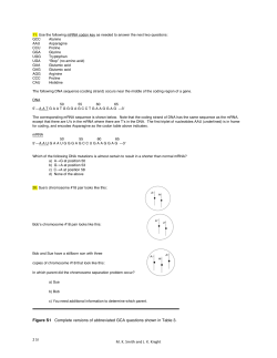
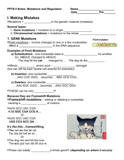
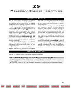
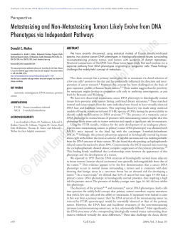


© Copyright 2026