
Document 243734
I’ ‘Jayne 17,1930.
_
c. w. EHLERS
'
1,765,217
FARM GATE
Filed June 8. 1928
I 3 Sheets-Sheet
1
'
/¢
_
1
(57672;? WZZ/ers
why»
~
June 17, 1930.
C. W. EHLERS
1,765,217
.
mam GATE
Filed June 8, 1928
5 Sheets-Sheet 2
lL
(/éreice
1
lnwenmr
ZZers' '
June 17, 1930. ‘
1,765,211
~ c. w. EHLERS
FARM GATE
s sheets-sheet '5
Filed June 8. 1928
/
7 ‘ .'
/
p.’
,7
.1
I
.
"
'
_
‘I: z‘ _
mr
4
Attorngy
Patented June 17, 1.930
, 1,765,217 H
i. mm STATES
CLARENCE w. nnnnns, ona'nnc'rron crmr,v KANSAS
FARM GATE
iApplication'?iled June-s, 192s.‘ serial‘ivo,'aea,aie.v
The present invention relates to gates and ' have
‘ '
disclosed a preferredvembodiment of- '
has for its principal object to? provide a my invention, the numeral 5 designates a
:vehicle operating. means therefor, whereby pair of uprights spaced apart vgate posts,
‘to open ‘or close they gate upon the approach a pair of said posts being disposed at each
‘5 of aivehiclel
still further‘ object. of the
I
"invention. is
side of thegate, each of said posts at their; 05
inner'lower edges being provided with‘a
to ‘construct the-gate of aj'pair of gate sec bracket 6 for supporting the ends of a shaft
tions, -'with'leach of ‘said sections arranged 7, extending between each pair of thelposts
for iverticalswinging vmovement. - ,
V 10
r
and formed; at the: outer lower corner’ ;of a I
I
.Another objectyof the invention-is to pro
vide a ‘vehicle operating means for each of
:the‘ gate. sections disposed remotely there;
from.
,7
,
.,
.
>
An additional object is to provide operat
1115 ing‘means for the sections of the gate dis
posed in advance of each sideofthe ‘gate,
and adapted- for moving, the sections into
‘gate
section ‘8..
~
'
~
'-
"
'
‘
-
The. gatesections may, be I constructed in 7
any manner well known’inithe art, suchias is
for instance, a rectangular ishaped, frames8,
having'a wire mesh9, attached to the mem
bers of said frame. :If desired, the ‘shaft 7:565
may be hinged, together with theflfr'ame’o'f "
the'gate section or may be formed separately‘
van'open or closed‘ position, depending upon and attached in any suitablemannerto the ,
the/direction of travel of the ‘vehicle. ' . "
Qlower outer edgevof the ‘frame as indicated 7
1.720‘ *Another object is to provide an apparatus inFigure/l of the drawings. Braces 10V may70
10f‘ this character of a simple vand practical also be provided for the opposite‘ends of'the
constructionywhich is strong anddu'rable, ‘shaft ‘and connectedto the bottom frame
te?icient and reliable" in performance, rela-, member of the gatewand rear-vertical frame
tively inexpensive to manufacture-and" as ‘members to" prevent bending of the shaft.
:jjg25 semble in operative position,‘ and otherwise The twosections of the'gate areiformedpin 53,5
well adapted to the purpose forlwhichthe “duplicate and cooperate to. close the ‘entrance
. ‘same‘is
fr Otherobjects
intended.v
of the' invention
j ,
will become
apparentas the nature of the invention-pro
"-1" no‘ceeds we and I when taken ' in’v connection.’ with
1 the , accompanying drawings. . ‘ I
1~-i:Inthe ‘drawing:
‘
'
=
.
‘
’
-
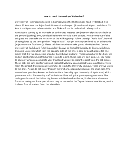
Figure 1, is a perspective view,‘ showing
the apparatus in assembled position. _
therebetween, the respective sections; being
mounted on vthe-gate posts.v By. reason of
the ‘horizontally disposed shaftu'z, ‘extending
transversely atthe rear edges of the zga'tefsec-‘iso 9"
tions, the vsections are thus adapted to. swing
1 vertically between the posts 5nand’at-ea‘ch
- side. ofevvthe entrance.‘ At the inner adjacent
edges-of. the, gate section is , arranged a latch
' ries? ‘Figure 2 is aside elevational viewtof one 11," secured at, one enact. the gate and 0115-9385 ‘
: tofthe‘ gate sections and the pivotal mount
pendingvdownwardly-with,its'opposite end' ~
,
freely- disposed anuadapted for engagement ‘
' ‘i1’, FigureB‘e is a perspectiveaviewi of‘one of with a ‘staple - 12 whichmay be .embedded in
' vt'he‘ssupportingtposts, illustrating the opera theground. at the." inner edges of-these sec; 7
‘e0 tive connection of the pivotal _; operating tions“ A pair of; posts ‘13, are arrangeldqatgao
I'ing therefor?-
'
'
-_
i
->
7 ‘ means with the-rock shaft‘ provided’ for op ' eachfsideaof ‘the gate: and a1 predetermined "
- eratio‘n upon‘; the passing of a"; vehicle'there vdistancetherefrom, Keachpair .of posts’being
v disposed r in" spacedrelation; at opposite‘ sides
.,~ Ei'gure axis a perspectivie'viewiof one
11.1.45f‘gate sections, and
I
'
1:
gietFigure .15 is " a1 similar,
'
-
'
the’
.71 l _
their ‘lower
which
edgesw1th'
endsof the
bearing
rQCk:_Sh8J.ft;151aI7e
brackets 14,1695
~ Y 1 ‘
’
7 the
gate,‘7 'iwithin
' . latch retaining stapleprovided forsecuring
I the gate sections in closed position.=~.
-'
_
v _ are provided adjacent
of .thedriveswayeand
, r .
Referring‘ now to the‘ ' drawings in’ detail,
v
journaled for-rotation.“ The shaft. '15 ex;
tends transversely. of thevdri'veways, and in
vteri'rnediate thenends-ris-forined1-withga vcr ank‘ '
_
a 9150 wherein for the purpose’ of‘ illustration 1' 16,:adapted normally to extend-_;vertica1lyei0o Y
s
_
‘
ifroaari
above the surface of'the ground for engage
ment by the wheels of the vehicle approach
ing the gate. Stakes 17 driven in the
ground adjacent each end of the crank 16
é‘supports the shaft, in order to ‘prevent the
nally extending brace rods 35 to the inter
mediateportion of each of which it attached
one end of a coil spring 36 and with they
opposite ends of the springs attached to the
post 5, whereby. to facilitate the vertical 70-"
. distortion thereof through the weight of the swinging movement of the gate. Each of
vehicle when passing: thereover. vAt each the springs 36 are connected with their re
end of {the shaft v:15 is a laterally extending spective posts by means of a section of chain
arm 18, to'which' one end of a coil spring 37, whereby to provide for the adjustment’
is attached'with its opposite end secured to of any tension of the spring. The ?exible 75
~ 'a bracket 20 extending from ‘the adjacent members'23 and 28 may comprise either a
post 13, whereby to yieldably retain ‘the chain as illustrated in the present embodicrank 16 of the shaft in an upwardly ex ment of the invention or may be in'the form ' .
tending position. Adjacenteachgend'ofthe of acableor rope for forming the connection
15Vshaft 15 is also arranged an operating. lever between the rock shaft and the respective
:21, extending :laterally from .the shaft and ‘portions of the gate. Aguard ‘38 is pro
.normally disposed vertically when the crank vide'd for each of ‘the :?exible'members dis
7
so 'i
116' ‘is disposed in a ‘vertical position. A posed adjacent'the operating lever :21, for
screweye 122 is attached at each side .of the the purpose of retaining .saidamembers' in - '
‘2(jFl6V8I‘ '21, adjacent the lower edge thereof, a longitudinally extendedpositionadjacent 85
:‘the screw .eye remote from theu-gate having .the opposite ‘sides of the lever. The upper
. .oneend of a ?exible operating member 23 . end of the operating'lever 21 ‘isformed in
attached .thereto, and extending upwardly
the shape of a fish tail as shown atx39, with '
10f the post 13, the operating member then
so .as to insure an engagementofthe lever
.over a .pulley '24, rota-tably supported in‘ a the opposite-ends thereof extendingttrans
,25 bracket 25‘attached adjacent the upper end versely with respect to the ‘?exible members
.
extending .in l a . direction :toward ‘the gate and
vover a pulley 26 mounted :in a bracket 27 at
' j the upper outer edge of the adjacent post 5.
.
90
therewith‘ upon movement v.of the lever vin
either direction.
'
‘
.
.
.It will'be apparent from-the foregoing
30 The opposite-end of the ?exible member that upon the approach ‘of the vehicle toward 95
v~231is ithenattached to the :rear frame member either side of the gate, the wheelsitliereof,
of the gate section at a point intermediate in’ riding over the crank 16 will rotate the
To the rock shaft and cause the :lever 21*to:move
nether ‘screw eye 22 carried by the operating downwardly ina directiontoward ‘the gate. J
-s5 @lever '21, disposed :at the side of. such lever, The initial movement of this 7 lever upon loo
adjacent the gate, is .attached one end of a engagement with the flexible member .28will
' ' :the top and bottom'aedges thereof.‘
?exible member ‘28, which ?exible member ioperate to release the‘latch' 11 and-:the‘sub- V
extends upwardly .over. a pulley '29, also sequent continued movement _ of :the lever
rotatably mounted in the bracket 24 at ‘the ‘will operate to raise each of the gate :sec
'
“.40 upper end;of_ the :post- 13, where the member .tions upwardlyand outwardlyvzat each'side‘
.then .exte'n‘dslin .a direction toward the gate of the post 5; ‘ After the vehicle has passed
and over a, pulley wheel '30 rotatably sup through the gate and coming into contact. 7 ported in‘ a bracket 31- .attached at the with :the crank 16 of the rock shaft at the
,
‘ upper .innervedge -of the adjacent post 5. ,--opposite side :thereof,which, it will'be underi 1475' The opposite :end'of the‘ ?exible member 28 stood, is unaffected by the'opening movement ' 119
" Q-is. [then vattached to ‘a lever v32 pivotally. of the gate, the lever 21 ‘associated with said‘
.mounted along :the' lower edge .of the gate last ‘named shaft will move away fromthe
lsection,jintermediate the inner and 1 outer gate, for engagement with the?'exiblefinem- ,
edgesthereof, said lever being adapted for‘ ber 23, whereby "through its ‘connection with j '
.50 pivotal movement longitudinally.ofj'the low
' ' * eriedgeoftheggate section. ' YTo thefree end
theouter edge of the gate, will gcause‘jthelns ' i
‘same to swing upwardly .andxinwardly' intoi '
‘of the lever v‘32' is {attached flexible member its closed position. After the vehiclezhas
133,‘- extending to the “latch "11 of saidtgate "passed overthe cranks ..=16,':the‘1spnings_19". if
. section‘, and adapted upon-the operation of will ‘then serveto return thecranks to their
#85 ‘said lever to release the latch ‘from its
*n'ormalupwardly disposed positions-1a ‘ 1 '
” ‘engagement withlthe staple‘lQ, andthus per- § I
i.
Itiis obvious that the. .iinventionisrsus-if‘
' I.-_mi_t vIthe' upward "swinging; movement of the cepti'bleiof various.changessandifgmodi?cw“ " . _
gate.‘ Each ‘of the I?exible members 23 and tions, without departing frQmthespirit-or f "
‘128 ‘have a weight ‘34' interposed‘ therein, be scope .of the invention.orsacri?cingany of. '~ 1
I :‘IQ-j-t-ween theepuIlley-wheelsv mounted on thepost its advantages, and 'I accordingl. claim all 1126
3 55,1 and :the'Pconnection :of said memberswi-th' esuch 'forms of the device tow ich; 11am
theggate whereby to maintain ‘said members
entitled}.
.
I
420
-~
1
-
"
‘
a
'
~
.
"
1 .
"
. '
in aatautcondition. 7
~
'
'
I
:
-
V
"
> At the lower {inner ‘corner lof‘e'ach: of the .
LA gate of theclass described coinprisl ‘
..f.6i"-.;gat'e%sections is arranged a pair‘lof engo ling av gate. section .pivotally mounted. atvits 1130 7' 'i
1,765,217
outer edge for upward swinging movement, additional ?exible operating members lead
a lever pivotally mounted on the lower edge ing from said shafts and having their oppo-i‘
of said gate section, means for actuating site
ends secured to said gate section, the end
said gate section for movingthe latter into of the
last mentioned ?exible operating
open and closed positions, said means com
members adjacent said shafts being disposed
prising a rock-shaft, means for mounting ‘ on the opposite sides of the operating levers
10
15
20
said rock-shaft remotely from said gate sec— of said shafts, whereby when said shafts are
tion, an operating lever mounted on said moved in an opposite direction said‘last men
rock shaft, spring means for, normally hold- tioned ?exible members will? be engaged by
ing the operating lever in a vertical position, said operating levers for actuating said last
a' pair of ?exible operating members, each
?exible operating members , to
of said operating members having onev end mentioned
effect movement of said gate section to the
thereof secured to said shaft on opposite closed position, said members arranged in‘
sides of said operating lever, one of said
first mentioned ?exible members for nor
?exible operating members having its other the
mally holding said ?exible members in a
end connected to said gate section rearwardly taut condition, and spring means engageable
thereof and intermediate the top and bottom with
said gate sectionfor urging said gate
edges of said gate section whereby when said section for movement to an open position
70'
7 ~
775
80.
shaft is moved in one direction for bringing upon , actuation of said ?rst mentioned
said operating lever into-engagement with
said one ?exible operating member, said gate
?exible members.
section will be actuated for movement‘from ‘
an open to a closed position, the other of said
’ '
'
*
In testimony whereof ‘I a?ix my signature. '
CLARENCE W. EHLERS.
pair of ?exible operating members having
its opposite end securedto said pivoted lever
carried by said gate vsection, latch means
carriedby said gate section normally secur
ing said section in closed position, means
operatively connecting said latch vmeans
s90
with said pivoted lever whereby when said
shaft is initially moved'in an opposite direc
95
tion, said operating lever will be'brought
into engagement with the other of said ?exi<
vCAI,
ble operating members, said latch mechanism
C1
will be released so that a subsequent move
ment of said , shaft may effect an upper
V
swinging movement ,of said gate section, all
100
in the. manner and for'the purpose set forth.
2. A gate of the class described/compris
vi0 ing a pair of gate sections‘pivotally mounted
at their outer edges for'upward swinging
105
movement, latch means carried by each of >
said gate sections for normally securing said
sections in closed position, means forsimul- v >
taneously moving said gate sections upon
their pivots to open and closed positions,
110.
said means comprising a pair’ of vehicle
operated rock shafts remotely disposed with
' respect to'said
‘
gate sections, operating levers
carried by said rock shaft, spring means for
normallyholding the operating levers in a
’
115
,
' vertical position, ?exible operating members r
extendingfrom each of said shafts, means
'operativelyconnecting said ?exible operat—
ing members with said latch means, the ends
of said ?exible operating .‘mernbers adjacent
said shafts being disposed ‘to ‘one side of the
i‘ ‘120
operating levers of saidshafts, whereby upon
initial movement of said shafts inrone direc- i
tion, said ?exible members will be actuated
for moving said latch means to a releasing
i
125
position, whereupon subsequent movement of
said shafts in the samegdirection willleffect
, a swinging movement ‘of said gate section
for moving said section to an open position,
130V
»


© Copyright 2026