
OPERATION AND INSTRUCTION MANUAL 8. CONNECTION DIAGRAM :
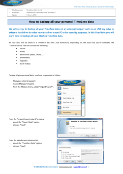
8. CONNECTION DIAGRAM :
ac, 3Phase, 4Wire, CT PT Operated Trivector Static Energy Meter
OPERATION AND INSTRUCTION MANUAL
ac, 3Phase, 4Wire, 3x63.5V, CT PT Operated, Class 0.2S
Static Energy Meter (for ABT application)
RS232
RS485
1 IN
1 OUT
2 IN
Y
2 OUT
3 IN
B
3 OUT
NIN
N
N OUT
RS232 Port
Rx
Tx
Vcc
GND
RS485 Port
1/21, Asaf Ali Road, New Delhi -110002, India, Phone : 91-11-23234411, 23234811
Fax: 91-11-23232639, Email: [email protected], Website: www.hplindia.com
Due to continuous development, specification and features are subject to change without prior notice.
GI
D
RE
HPL ELECTRIC & POWER PVT. LTD.
X
E
X
A
B
A = Data (+)
B = Data (-)
ABT SAMPLE
METER TERMINAL
BLOCK
S T ER
UKAS
QUALIT Y
MANAGEMEN T
003
HPL Electric & Power Pvt. Ltd.
India
6.
Table of Contents
TECHNICAL SPECIFICATION OF METER :
1. Enclosure
:
Engineering plastic
2. Display
:
Backlit LCD display
Large digit size 10 mm x 5 mm
1.
General Information ..................................................................... 2
2.
Front View/Panel Description ..................................................... 2
3.
Technical Features ...................................................................... 3
3. Protection Index
:
IP51
4. System
:
ac 3 Phase, 4 Wire
5. Inputs
:
a. Current Rating : -/1A or -/5A
Starting Current : 1mA for -/1A,
3.1
Energy Registers ............................................................... 3
3.2
Maximum Demand & MD Integration Period ....................... 3
3.3
Maximum Demand Reset .................................................... 3
Rated : 3x63.5V
3.4
Load Survey ...................................................................... 3
Variation : -20% to +15%
3.4.1 Block Load Profile Parameters ............................... 3
c. Rated Frequency: 50 Hz
5mA for -/5A
b. Voltage
3.4.2 Daily Load Profile Parameters ................................ 4
3.5
Power Fail Record ............................................................. 4
3.6
Time of Day (TOD) ............................................................. 4
3.7
Display Details .................................................................... 4
3.7.1 Auto Scroll Mode .................................................... 4
3.8
4.
Variation : ±5%
6. Class of Accuracy
:
Class 0.2S for Active Energy &
Class 0.2S for Reactive Energy
7. Applicable Standards
7.
:
IS 14697 : 99
INSTALLATION :
3.7.2 Push Button Mode .................................................. 6
a. Refer to the connection diagram shown in the manual.
3.7.3 Test Display Mode .................................................. 7
b. Ensure that the cable connections are properly connected as per connection
Occurrence Tamper ID ....................................................... 8
diagram.
Communication ............................................................................ 9
4.1
Communication Interface ................................................... 9
4.2
Programmable Parameters ................................................. 9
4.3
Data Collection ................................................................... 9
5.
Tamper Threshold Limits ............................................................. 9
6.
Technical Specification of Meter ............................................... 10
7.
Installation .................................................................................. 10
8.
Connection Diagram .................................................................. 11
-1-
- 10 -
4. COMMUNICATION :
1. GENERAL INFORMATION :
4.1 Communication Interfaces : Three communication interfaces are as
follows:
a. Optical Port (9600 bps)
b. RS232 Port (9600 bps)
c. RS485 Port (9600 bps)
d. Simultaneous Communication can be performed with :
(i) Optical & RS232
(ii) Optical & RS485
4.2 Programmable Parameters : Programmable parameters via communication
are as follows:
a. Date and Time
b. Demand Intergration Period
c. Profile Capture Period (Load Survey Integration Period)
d. Time of Day (TOD)
e. Date of Billing
4.3 Data Collection : Following data can be collected via communication:
a. Instantaneous parameters (At the time of meter reading).
b. Block Load Survey (For last 30 days).
c. Daily Load Survey (For last 30 days).
d. Billing Parameters (For last 12 billing).
e. Power ON/OFF Events. (20 Nos.)
f . Transaction Events. (10 Nos.)
g. Tamper Events. (200 Nos.)
a. Meter measures active, reactive & apparent energies in forward and reverse direction &
in all four quadrant kWh and kVArh pulse output LEDs available on front panel.
b. LCD with backlight feature and LCD segments for indicating presence of voltage in
each phase separately are available.
c. Push Buttons are provided for scrolling the display parameters as well as for display
during Power failure.
d. Internal battery provided to view display and collect data during power failure.
e. Rugged polycarbonate casing makes it a good insulator and so no external “EARTHING
TERMINAL” is required.
f . RTC with battery backup is used for time keeping with calendar of 100 years.
g. Definition of quadrants used in this documents are as follows:
Quadrant 2
kW export
kVAr import
(capacitive)
Q1
Q2
kW
- Å
kVAr + Æ
S
Q
kW
- Å
kVAr - Å
5. TAMPER THRESHOLD LIMITS:
THRESHOLDS FOR TAMPER EVENTS
1. MISSING POTENTIAL
a. Voltage in tamper phase
b. Current in tamper phase
2. VOLTAGE UNBALANCE
a. All Voltage
b. Diff. b/n Phase Voltage
3. CT POLARITY REVERSAL
a. Voltage in tampered phase
b. Current in tampered phase
c. Power factor
4. CURRENT UNBALANCE
a. All Voltage
b. Diff. b/n Phase Current
Occ.
Limit
Occ.
Time
Restoration
Limit
5 minutes
<70% Vref
>5% Ib
Q4
>70% Vref
Diff. >10% of
highest Voltage
5 minutes
5 minutes
>70% Vref
<2% Ib
>5% Ib
6. LOW PF
PF<0.5%
80
b
c
d
e. Push Button (Forward) : Display Mode
Selection/Forward Scroll
1
80
15 minutes
>70% Vref
>5% Ib
Ignore
PF>0.6%
a
d. Active Energy (kWh)
Pulse Indication
15 minutes
15 minutes
a. LCD
c. Reactive Energy (kVArh)
Pulse Indication
>70% Vref
Diff. <20% of
highest current
5 minutes
Quadrant 4
b. Optical Port (with sealing provision)
5 minutes
15 minutes
5. CT OPEN
a. Voltage in tamper phase
b. Current in tampered phase
c. Current in other phase/phases
0
>70% Vref
>5% Ib
(In forward
direction)
>0.1
>70% Vref
Diff. >30% of
highest current
Quadrant 3
2. FRONT VIEW/PANEL DESCRIPTION :
>70% Vref
Diff. <5% of
highest Voltage
>70% Vref
>5% Ib
(In reverse
direction)
>0.1
kW import
kVAr export
(capacitive)
5 minutes
5 minutes
5 minutes
2
40
e
f . Push Button (MD Reset) : MD Reset (with
sealing provision)
f
g
g. Push Button (Backward) : Display Mode
Selection/Backward Scroll
h
h. Push Button (Battery) : To be used for
display in absence of mains supply
i
i.
RS232 Port (with sealing provision)
j.
RS485 Port (with sealing provision)
j
k
k. Terminal Cover (with sealing provision)
-9-
kW + Æ
kVAr - Å
kW export
kVAr export
(Inductive)
Restoration CompartNo. of Tamper
Time
ment No. Events(Occ.+Rest.)
>75%Vref
>5% Ib
kW + Æ
kVAr + Æ
P
Q3
TAMPER EVENT
Quadrant 1
kW Import
kVAr Import
(Inductive)
-2-
3. TECHNICAL FEATURES :
5. High Resolution kVArh Quadrant 1
3.1 ENERGY REGISTERS : The meter measures following energies.
0005.4180
K VArh
0008.5121
K VArh
0006.1241
KVArh
h
i. Fundamental Only :
a.
b.
c.
d.
e.
f.
g.
h.
i.
j.
k.
l.
Active Energy Import
Active Energy Export
Apparent Energy Import
Apparent Energy Export
Reactive Energy (Quadrant 1)
Reactive Energy (Quadrant 2)
Reactive Energy (Quadrant 3)
Reactive Energy (Quadrant 4)
Reactive Energy High (V>103%Vref)
Reactive Energy Low (V<97%Vref)
Reactive Energy Low (V<70%Vref)
Reactive Energy Between (97%Vref<V<103%Vref)
6. High Resolution kVArh Quadrant 2
h
7. High Resolution kVArh Quadrant 3
h
8. High Resolution kVArh Quadrant 4
-3-
KVArh
0020.1230
KWh
h
9. Total Import kWh (Fundamental + Harmonics)
IMPORT
ii. Total (Fundamental + Harmonics) :
a. Active Energy Import
b. Active Energy Export
Note : Total energies are provided only on display. All the calculations are based on
fundamental only energies.
3.2 MAXIMUM DEMAND AND MD INTEGRATION PERIOD :
The demand is monitored during each demand interval set with 15 minutes integration
and the maximum of these demand is stored as maximum demand along with date & time.
Demand integration periods of 15, 30 minutes are programmable.
3.3 MAXIMUM DEMAND RESET : It is possible to reset the MD in following three ways.
a. MD Reset Button : On pressing MD reset Button continuously for 5 seconds,
“
”on display indicates MD has been reset successfully. Only one manual
MD reset operation shall be possible in any given 15 minutes. The MD reset button
shall be ignored if a manual MD reset operation has already occurred within 15
minutes.
b. Communication driven reset : It shall be ignored if communication driven
reset option has already occurred with in 15 minutes.
c. Automatic resetting at the end of pre-specified date and time of each calendar
month (e.g.00:00 hrs. of 1st day of each month).
3.4 LOAD SURVEY : The following load survey parameters are provided for last 30
days.
3.4.1 BLOCK LOAD PROFILE PARAMETERS (INTEGRATION PERIOD 15 MINUTES) :
a. Real Time Clock - Date & Time
b. Phase wise average Current
c. Phase wise average Voltage
d. Active Energy-kWh (Import)
e. Active Energy-kWh (Export)
f . Net kWh (Import-Export)
g. Apparent Energy-kVAh (Import)
h. Apparent Energy-kVAh (Export)
i. Reactive Energy-kVArh (Quadrant 1)
j. Reactive Energy-kVArh (Quadrant 2)
k. Reactive Energy-kVArh (Quadrant 3)
l. Reactive Energy-kVArh (Quadrant 4)
m. Demand kW (Import)
n. Demand kW (Export)
o. Demand kVA (Import)
p. Demand kVA (Export)
q. Average PF (Import)
r. Average PF (Export)
s. Average Frequency (Hz)
t. Coded Frequency (00-99)
Load survey integration periods of 15, 30 minutes are programmable.
0004.3218
h
0018.1231
10. Total Export kWh (Fundamental + Harmonics)
EXPORT
KWh
h
Note : Following icon shall be displayed to show status of various condition as given below.
i.
“ ”, “ ” , “ ” enunciator indicates presence of the respective phase.
ii.
Presence of “
iii.
“
” Appear whenever Communication take place.
iv.
“
” Icon shall blink on display if meter cover is opened.
v.
Battery Mode : All Display Mode parameters are available in battery mode.
vi.
Scroll Lock/Unlock :
” and Blinking of “
”, “
”, “
” indicates reversal of current of respective phase.
a. To Scroll Lock/Unlock the desired parameter, press Scroll Button for 8 seconds.
b. The Meter shall return to auto scroll display mode if the scroll lock is inactive & push button
not operated for 60 seconds.
c. If scroll lock is active then display will unlock automatically after 10 minutes.
*3.8 . OCCURRENCE TAMPER ID SHALL BE AS FOLLOWS :
a. If Missing Potential has occurred in R phase, display shows “
PH-FAIL ”
b. If Missing Potential has occurred in Y phase, display shows “ PH-FAIL ”
c. If Missing Potential has occurred in B phase, display shows “ PH-FAIL ”
d. Voltage Unbalance has occurred, display shows “ u l -u
”
e. If CT Reversal has occurred in R phase, display shows “ C - EU ”
f . If CT Reversal has occurred in Y phase, display shows “ C - EU ”
g. If CT Reversal has occurred in B phase, display shows “ C - EU ”
h. If CT Open has occurred in R phase, display shows “ C - PE ”
i. If CT Open has occurred in Y phase, display shows “ C - PE ”
j. If CT Open has occurred in B phase, display shows “
C - PE ”
k. If Current Unbalance has occurred, display shows “
”
l. If Low PF has occurred, display shows “ l -pf ”
-8-
8. Cumulative Reactive Energy High (V>103%)
00008.982
KVArh
9. Cumulative Reactive Energy Low (V<97%)
00006.827
KVArh
10. R - Phase Voltage THD%
0.0
11. Y - Phase Voltage THD%
0.0
12. B - Phase Voltage THD%
0.0
3.5 POWER FAIL RECORD :
Power On/Off event is recorded whenever power goes off for more than 5 minutes.
0.0
13. R - Phase Current THD%
14. Y - Phase Current THD%
0.0
15. B - Phase Current THD%
0.0
MD
16. Last Reset Maximum kVA Import
IMPORT
0.952
KVA
01.08.13
17. Last Billing Reset Date & Time
occ
09.09.13
17.01
3.7.3
Test Display Mode : Test Display Mode always displays following parameters
using forward button & backward button.
Parameters in Test Display Mode
Typical Screen Shots
0020.1230
1. High Resolution kWh Import
IMPORT
EXPORT
IMPORT
EXPORT
-7-
3.7.1 Auto Scroll Mode : Auto Scroll Mode always displays following parameters
with scrolling time of 10 seconds. These parameters are also available in mode 1 using
forward & backward scroll button.
Typical Screen Shots
Parameters in Auto Scroll Mode
@8.8.8.8.8.8.8
1. Display Check
IMPORT
EXPORT
KWh
K VA h
18.8.8.8.8.8.8
MD
X10000
K VVA r h z
T.8
123456
2. Meter Serial No.
09.09.13
3. Real Date & Time
h
0018.1247
4. High Resolution kVAh Export
t-xxx.XX
h
0020.1240
3. High Resolution kVAh Import
KWh
h
0018.1231
2. High Resolution kWh Export
3.7 DISPLAY DETAILS : As soon as the meter is powered On, it shall show the Version
Number of the firmware.
Then it will move to Auto Scroll Mode of display.
There are three modes of display:
3.7.1) Auto Scroll Mode (Mode 1)
3.7.2) Push Button Mode (Mode 2)
3.7.3) Test Display Mode (Mode 3)
l -pf
19. Last Tamper Occurrence Date & Time*
3.6 TIME OF DAY (TOD) : Default 8 TOD Zones timings are given below :
TOD “1” - 00:00 Hrs. to 03:00 Hrs.
TOD “2” - 03:00 Hrs. to 06:00 Hrs.
TOD “3” - 06:00 Hrs. to 09:00 Hrs.
TOD “4” - 09:00 Hrs. to 12:00 Hrs.
TOD “5” - 12:00 Hrs. to 15:00 Hrs.
TOD “6” - 15:00 Hrs. to 18:00 Hrs.
TOD “7” - 18:00 Hrs. to 21:00 Hrs.
TOD “8” - 21:00 Hrs. to 00:00 Hrs.
Firmware Version Number
00.00
18. Last Tamper Occurrence Type*
3.4.2 DAILY LOAD PROFILE PARAMETERS :
a. Real Time Clock - Date
b. Cumulative Active Energy-kWh (Import)
c. Cumulative Active Energy-kWh (Export)
d. Cumulative Apparent Energy-kVAh (Import)
e. Cumulative Apparent Energy-kVAh (Export)
f . Cumulative Reactive Energy-kVArh (Quadrant 1)
g. Cumulative Reactive Energy-kVArh (Quadrant 2)
h. Cumulative Reactive Energy-kVArh (Quadrant 3)
i. Cumulative Reactive Energy-kVArh (Quadrant 4)
j. Cumulative Reactive Energy High (V>103%Vref)
k. Cumulative Reactive Energy Low (V<97%Vref)
l. Cumulative Reactive Energy Low (V<70%Vref)
m. Cumulative Reactive Energy Between (97%Vref<V<103%Vref)
n. Total Tamper Count
o. Power Fail Count
17.01.37
KVA h
00020.123
4. Cumulative kWh Import
h
IMPORT
-4-
KWh
Typical Screen Shots
5. Cumulative kVArh Quadrant 1
00005.418
6. Cumulative kVArh Quadrant 2
7. Cumulative kVAh Import
KVArh
22. R - Phase Voltage
00008.512
KVArh
23. Y - Phase Voltage
00020.124
KVA h
24. B - Phase Voltage
63.50
V
Typical Screen Shots
IMPORT
pf
8. Average Power Factor Import
IMPORT
9. Maximum Demand in kVA Import
IMPORT
10. Cumulative Maximum Demand in kVA Import
IMPORT
V
Typical Screen Shots
63.50
V
Typical Screen Shots
1.000
5.000
25. R - Phase Current
aug
A
Typical Screen Shots
MD
0.952
KVA
1.905
KVA
27. B - Phase Current
KWh
28. Instantaneous PF (Lag/Lead)
00018.123
11. Cumulative kWh Export
63.50
5.000
26. Y - Phase Current
A
Typical Screen Shots
MD
5.000
PF
A
1.000
EXPORT
12. Cumulative kVArh Quadrant 3
00006.124
KVArh
29. MD Reset Count
13. Cumulative kVArh Quadrant 4
00004.321
KVArh
30. Instantaneous Frequency
14. Cumulative kVAh Export
00018.124
KVA h
EXPORT
2
f
pf
EXPORT
16. Maximum Demand in kVA Export
EXPORT
17. Cumulative Maximum Demand in KVA Export
EXPORT
f
18. Last Block Average Frequency
1.000
Push Button Mode : Push Button Mode always displays following parameters
using forward button & backward button.
Typical Screen Shots
20. Signed Net kVArh High (V>103%)
KVA
1.905
KVA
-5-
18.8.8.8.8.8.8
MD
X10000
K VVA r h z
T.8
123456
2. Meter Serial No.
MD
5.23
3. Cumulative Meter Off Duration
POFF H
Typical Screen Shots
50.000
hz
aug
KWh
100
4. Instantaneous Average Percent Voltage
5. Instantaneous Active Power with Sign (+/-)
0.952
KW
0.234
KVArh
6. Instantaneous Reactive Power with Sign (+/-)
0.000
K VAr
1.234
KVArh
7. Instantaneous Apparent Power
0.952
K VA
h
21. Signed Net kVArh Low (V<97%)
IMPORT
EXPORT
MD
0.952
-1.112
19. Last Block Net kWh Transmitted with +/-
@8.8.8.8.8.8.8
1. Display Check
aug
hz
3.7.2
Parameters in Push Button Mode
15. Average Power Factor Export
50.000
-6-


© Copyright 2026