
Ultrathin Slab Gel Separations of DNA Using a
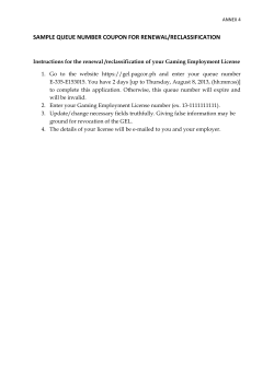
Anal. Chem. 1997, 69, 2292-2298
Ultrathin Slab Gel Separations of DNA Using a
Single Capillary Sample Introduction System
Paula Beyer Hietpas, Katherine M. Bullard, David A. Gutman, and Andrew G. Ewing*
Department of Chemistry, The Pennsylvania State University, University Park, Pennsylvania 16802
We demonstrate here a novel method for DNA separations
which combines the parallel processing capabilities of slab
gels with the advantages of sample introduction obtained
with a single capillary. This sample introduction format
allows rapid sequential separations or continuous analysis
to be carried out on ultrathin slab gels with efficient heat
dissipation. Ultrathin slab gels have been fabricated by
using 57-µm spacers between quartz plates, and a single
capillary has been used to introduce plugs of dsDNA
fragments into the ultrathin gel. These fragment plugs
were deposited along the entrance to the ultrathin gel at
spatially discrete locations by micromanipulation of the
capillary. Spatially resolved detection has been accomplished with an argon ion laser focused to a line for
excitation and a CCD for collection of fluorescence.
Double-stranded DNA separations are demonstrated in
a plug injection format. This approach allows multiple
unique samples to be rapidly deposited on the ultrathin
slab gels for separation.
Molecular biologists have used the sized-based separation
technique of gel electrophoresis for decades. It has proved useful
for separations of DNA fragments in such varied means as
pathogen detection,1,2 restriction mapping3,4 and sizing of large
DNA fragments.5,6 Increases in speed and resolution of the gelbased methods have extended their use to include separations of
smaller-sized restriction fragments7-12 and DNA sequencing
reaction products.13-20 These increases in speed and resolution
(1) Mayer, A.; Sunzer, F.; Lee, T. H.; Busch, M. P. Arch. Pathol. Lab. Med. 1991,
115, 1228-1234.
(2) Schwartz, H. E.; Ulfelder, K.; Sunzeri, F. J.; Busch, M. P.; Brownlee, R. G.
J. Chromatogr. 1991, 559, 267-283.
(3) Maschke, H. E.; Frenz, J.; Belenkii, A.; Karger, B. L.; Hancock, W. S.
Electrophoresis 1993, 14, 509-514.
(4) Milofsky, R. E.; Yeung, E. S. Anal. Chem. 1993, 65, 153-157.
(5) Guszczynski, T.; Pulyaeva, H.; Tietz, D.; Garner, M. M.; Chrambach, A.
Electrophoresis 1993, 14, 523-530.
(6) Heiger, D. N.; Cohen, A. S.; Karger, A. L. J. Chromatogr. 1990, 516, 3348.
(7) Chan, K. C.; Whang, C.-W.; Yeung, E. S. J. Liq. Chromatogr. 1993, 16, 19411962.
(8) Srinivasan, K.; Girard, J. E.; Williams, P.; Roby, R. K.; Weedn, V. W.; Morris,
S. C.; Lkine, M. C.; Reeder, D. J. J. Chromatogr. A 1993, 652, 83-91.
(9) McCord, B. R.; McClure, D. L.; Jung, J. M. J. Chromatogr. A 1993, 652,
75-82.
(10) Williams, P. E.; Marino, M. A.; Del Rio, S. A.; Turni, L. A.; Devaney, J. M.
J. Chromatogr. A 1994, 680, 525-540.
(11) Clark, S. M.; Mathies, R. A. Anal. Biochem. 1993, 215, 163-170.
(12) Zhu, H.; Clark, S. M.; Benson, S. C.; Rye, H. S.; Glazer, A. N.; Mathies, R.
A. Anal. Chem. 1994, 66, 1941-1948.
(13) Luckey, J. A.; Drossman, H.; Kostichka, A. J.; Mead, D. A.; D’Cunha, J.;
Norris, T. B.; Smith, L. M. Nucleic Acids Res. 1990, 18, 4417-4421.
(14) Stegemann, J.; Schwager, C.; Erfle, H.; Hewitt, N.; Voss, H.; Zimmermann,
J.; Ansorge, W. Nucleic Acids Res. 1991, 19, 675-676.
2292 Analytical Chemistry, Vol. 69, No. 13, July 1, 1997
have resulted from the implementation of analytical techniques
such as capillary gel electrophoresis,4,7-10,13 ultrathin slab gel
electrophoresis,14-18 and capillary array electrophoresis.11,12,19,20 The
fundamental advantage of these techniques lies in the increased
heat dissipation that results when the surface area-to-volume ratio
of the gel is increased, allowing higher potential fields to be used
for the separation and, consequently, decreasing the separation
time. Capillary gel electrophoresis in particular has received
considerable attention due to the ease of sample introduction. On
the other hand, the methods of ultrathin slab gel electrophoresis
and capillary array electrophoresis allow multiple separations to
be carried out in parallel, increasing the information capacity of a
single run; however, the sample introduction methods for these
high-throughput systems are currently rather complex.
The method described here combines the parallel processing
capabilities of the ultrathin slab gels with the advantages of sample
introduction generally found with a single capillary. This results
in a similar throughput to the capillary array electrophoresis
systems without the need to address a large array of capillary
entrances. In this method, solutions of double-stranded (ds) DNA
fragments are introduced into an ultrathin slab gel by way of a
single capillary. The capillary is translated along the entrance to
the ultrathin slab gel, depositing DNA fragments which are
separated in different lanes on the gel. These lanes are not
physical barriers designed into the gel but are apparent lanes,
the result of migration of a DNA fragment plug in a straight line
from the gel entrance to the detection region. The DNA
fragments are electrokinetically transferred into the thin slab gel
as opposed to being loaded into individual wells in the gel.
In this article, we describe the use of a novel system for sample
introduction and separation of DNA fragments. The sample
introduction system relies on the idea that DNA fragments have
approximately the same mass-to-charge ratio regardless of size;
therefore, all of the fragments from a restriction digest, for
example, will migrate as a single plug through a free solution
capillary. The system not only is used for the repeated transfer
of the same sample to the gel but also can be used for transferring
unique DNA samples to each separation lane in the gel.
(15) Brumley, R. L.; Smith, L. M. Nucleic Acids Res. 1991, 19, 4121-4126.
(16) Kostichka, A. J.; Marchbanks, M. L.; Brumley, R. L.; Drossman, H.; Smith,
L. M. Bio/Technology 1992, 10, 78-81.
(17) Chen, D.; Peterson, M. D.; Brumley, R. L.; Giddings, M. C.; Buxton, E. C.;
Westphall, M.; Smith, L.; Smith, L. M. Anal. Chem. 1995, 67, 3405-3411.
(18) Carninci, P.; Volpatti, F.; Schneider, C. Electrophoresis 1995, 16, 18361845.
(19) Huang, X. C.; Quesada, M. A.; Mathies, R. A. Anal. Chem. 1992, 64, 21492154.
(20) Ueno, K.; Yeung, E. S. Anal. Chem. 1994, 66, 1424-1431.
S0003-2700(97)00070-X CCC: $14.00
© 1997 American Chemical Society
EXPERIMENTAL SECTION
Chemicals. Acrylamide stock solution, tris(hydroxymethyl)aminomethane (tris), boric acid, hydrofluoric acid (HF), and
[γ-(methacryloxy)propyl]trimethoxysilane were purchased from
Sigma Chemical Co. (St. Louis, MO). Ethylenediaminetetraacetic
acid disodium salt (EDTA) was obtained from Fisher Scientific
Co. (Fairlawn, NJ), and ammonium persulfate (APS) and N,N,N′,N′tetramethylethylenediamine (TEMED) were purchased from Aldrich Chemical Co. (Milwaukee, WI).
HaeIII-digested ΦΧ174, PBR322, and PUC18 dsDNA were
obtained from Sigma and were used without dilution. Ethidium
bromide intercalating dye was obtained from Molecular Probes
Inc. (Eugene, OR) and was used only in the separation buffer at
a concentration of 0.500 mg/500 mL.
Ultrathin Slab Gel Construction. The channel structure in
which the ultrathin slab gels were cast is similar to that used by
Mesaros et al. for free solution continuous separations.21,22 The
channels were constructed of two pieces of polished quartz (16
cm long × 5 cm wide and 1/4 in. thick) purchased from Technical
Glass Products, Inc. (Mentor, OH). One end (5 cm) of each
quartz plate was ground to an angle of approximately 45°. Thus,
when the channel structure was formed, there was a beveled
entrance that facilitated the alignment of the sampling capillary
diameter with the gel entrance. Scotch tape (3/4 in. wide, 3M,
St. Paul, MN) was used as a spacer to define the channel
thickness. A piece of tape 16 cm long and trimmed to 0.5 cm
wide was placed along each edge of one quartz plate. When the
second plate was placed on top of the first plate, a rectangular
opening was formed between the two, with an internal height of
57 µm.
Prior to casting the ultrathin slab gels, the quartz plates were
immersed in a 0.5%(v/v) [γ-(methacryloxy)propyl]trimethoxysilane solution in 1:1 acetic acid/H2O for at least 15 min so that
the polyacrylamide would cross-link to the quartz plates and
prevent migration of the gel out of the channel. The plates were
then rinsed with water and/or 95% ethanol and dried. Special
care was taken so that any residue on the plates was wiped clean
and there were no streaks.
A 6% solution of acrylamide was prepared from a 40% acrylamide/bisacrylamide stock solution, 100 mM tris-borate-EDTA
(TBE) buffer, and deionized water. This gel solution was then
degassed for 10 min prior to the addition of the polymerization
initiators, 10% APS and TEMED. This solution was poured
immediately onto the quartz plate with the tape on the sides, and
the second quartz plate was placed on top of the first, causing
any excess gel solution to spill out of the channel. Immediately
after pouring, the two plates were held together with 3/4-in. Acco
binders along the taped edges. The edges were then sealed with
Devcon Corp. (Danvers, MA) 5-min epoxy. The solution was
allowed to polymerize for 1 h, during which time the epoxy cured,
allowing the removal of the Acco binders. During the polymerization period, the entrance and exit ends of the ultrathin slab
gel were saturated with buffer solution, which appeared to
decrease gel shrinkage. Several methods of filling the rectangular
channel with gel solution after it was constructed were attempted
but resulted in multiple bubbles, premature cross-linking, or
extreme difficulty in taking the channel apart. The method used
(21) Mesaros, J. M.; Luo, G.; Roeraade, J.; Ewing, A. G. Anal. Chem. 1993, 65,
3313-3319.
(22) Mesaros, J. M.; Ewing, A. G. J. Microcolumn Sep. 1994, 6, 483-494.
Figure 1. Schematic diagram of system setup. See text for details.
was very simple and reproducibly produced 57-µm-thick gels
which were virtually bubble free.
After complete polymerization, the ultrathin slab gel was
suspended across two buffer reservoirs filled with 100 mM TBE
buffer with ethidium bromide added, as shown in Figure 1. The
buffer reservoirs were constructed from quartz (used for rigidity)
in a similar configuration as was previously described.21,22 The
channel was suspended across the two buffer reservoirs, and Dow
Corning high-vacuum grease (Midland, MI) was used both to
secure the channel in place and to ensure isolation of the two
buffer reservoirs. A platinum electrode was epoxied into each
buffer reservoir, and a Bertan high-voltage power supply was used
to provide the separation voltage. The gel was preelectrophoresed
for 30 min at 2.0 kV (125 V/cm), the same voltage that was used
during the experiments.
Capillary Transfer. The fused silica transfer capillary (50µm i.d., 362-µm o.d.) was purchased from Scientific Resources,
Inc. (Eatontown, NJ). This sulfonic acid-coated capillary was used
for efficient transfer of all DNA fragments in a single plug. The
exit end of this capillary was etched in HF to an o.d. of 70-110
µm as previously described,23 and this etched tip was then easily
positioned in the beveled entrance to the ultrathin slab gel.
Prior to experiments, the capillary was filled with 100 mM TBE
buffer, and a potential field of -3 to -15 kV was applied across
the length of the capillary. This potential field was applied with
a Spellman high-voltage power supply (Plainview, NY) with the
ground end at the capillary/gel juncture. In this way, the
transferring potential was controlled independently of the separation field. Transfer of DNA plugs through the capillary was
accomplished through electromigration. To make a plug injection,
the entrance end of the capillary was moved to a vial of dsDNA,
and a potential was applied across the length of the capillary for
3 s, followed by a 3-6-min plug of buffer to act as a spacer between
consecutive plugs of DNA.
The transfer capillary was translated along the entrance of the
slab gel by use of a Hurst (Princeton, NJ) stepper motor, which
was controlled as previously described21,22 via a Gateway 2000
computer (Sioux Falls, SD) with in-house-written software. The
timing of the capillary movement was correlated with the expected
(23) Olifirowicz, T. M.; Ewing, A. G. Anal. Chem. 1990, 62, 1872-1876.
Analytical Chemistry, Vol. 69, No. 13, July 1, 1997
2293
elution time of the consecutive DNA plugs. The capillary was
either moved at a rate of 20 ms/step with each step 25.4 µm at a
time when buffer alone was eluting from the capillary or was
continuously moved at a rate of 2500 ms/step, which corresponds
to approximately 2 mm every 3 min, allowing a 2-mm spacing
between each plug.
Detection System. The detection system used here was
similar to that described by Smith et al.16 and met the requirement
of maintaining spatial integrity of the data across the width of the
gel. The main components were a high-powered argon ion laser
(6 W, Coherent, Santa Clara, CA) and a cryogenically cooled
charge-coupled device (CCD) detector (Photometrics, Tucson,
AZ). For the experiments shown here, the laser was used in the
single-wavelength (514 nm) mode. The Photometrics CCD has
a rectangular detection array of 1024 × 256, with each detection
element 27 × 27 µm2. Each detection element was read out
individually or binned with consecutive elements and read out as
a group. For these experiments, binning was done in only one
dimension.
The 514-nm line from the argon ion laser was expanded with
a Newport Optics beam expander (20×, Irvine, CA). The beam
was then directed with two mirrors (Newport Optics) through a
cylindrical lens (50.8 mm × 50.8 mm, F ) 150 mm, Newport
Optics) that shaped the expanded beam into a line approximately
5 cm long and 500 µm in width. This reshaped laser line was
focused onto the top quartz plate at Brewster’s angle to ensure
minimum loss of power due to reflection and maximum transmittance of light into the detection region of the ultrathin slab gel.
Fluorescence emitted by the excited DNA:dye complex as it
migrated through the 500-µm detection region was collected at
an angle of 90°. It passed through a 550-nm-cutoff filter to
eliminate stray light, including reflected laser light, and was
demagnified 1.1 times by a 60-mm Nikkor camera lens (Nikon,
f2.8) before reaching the CCD camera.
Data Collection and Analysis. The CCD was controlled
using a Photometrics AT200 card in a Micron Pentium 133-MHz
computer (Micron Electronics, Inc., Nampa, ID) and CCD9000
software (Photometrics). The detection region of the thin slab
gel was focused onto a 1024 × 10 pixel array of the CCD. A new
image was taken every second, and this 1024 × 10 pixel array
was binned to a 1024 × 1 array. The CCD9000 software allowed
4200 consecutive images of this size to be stored in a single file.
This file was then analyzed using on a Micron Dual-Pentium 133
Powerserver using Transform 2D (Fortner Research LLC, Sterling,
VA) software.
A signal-averaging background subtraction program was written in-house using the Labview programming language. This
subtraction program was used only when a constantly high
background was observed in specific regions of the channel. This
usually indicated that the channel plates were either smudged or
scratched, causing more reflection than usual at these points.
However, this apparently did not inhibit detection of fragments
at this location, because removal of the higher background at
these points resulted in visualization of masked DNA bands.
Safety Concerns. Care was taken when handling acrylamide
monomers and the ethidium bromide dye, as they are toxic. In
addition, investigators were removed from contact with the highvoltage power supply.
2294
Analytical Chemistry, Vol. 69, No. 13, July 1, 1997
RESULTS AND DISCUSSION
Overview of Capillary Transfer System. A schematic of the
entire system is shown in Figure 1 and is broken down into three
main components: the transfer capillary, the gel separation
system, and the detection system. The transfer capillary is used
to introduce analyte solutions, in this case the dsDNA solutions,
into the slab gel. This can be done via either pressure (data not
shown) or electromigration. In the case of electromigration, the
transferring potential is controlled independently of the separation
field. The beveled edges of the channel ensure accurate alignment
of the capillary/slab gel bores. By translating the capillary along
the entrance to the ultrathin slab gel, the analyte solution can be
introduced to the slab gel along its entire 4-cm width. If analyte
solution is continuously flowing through the capillary, this translation results in continuous introduction of analyte into the gel. If,
however, the analyte solution is injected as discrete plugs with
buffer in between them, continuous translation of the capillary
results in individual injection plugs of analyte solution being
introduced into the thin slab gel.
The separation system is comprised of the ultrathin slab gel
suspended across two buffer-filled reservoirs. The system is
arranged so that the sample introduction end of the gel is held at
ground and the negatively charged fragments of dsDNA migrate
toward the positively charged anode. Thus, when a high-potential
field is applied across the length of the ultrathin slab gel,
electromigration of species is induced. The beveled entrance to
the slab gel channel provides an optimal connection between the
capillary and channel. DNA labeling by intercalation of ethidium
bromide occurs in the separation system before the fragments
pass through the detection zone.
As the separated DNA fragments migrate through the detection zone, the fluorescence from the intercalating dye is collected
via a CCD, which maintains the spatial integrity of the fragments.
Since the DNA solution is deposited sequentially across the
entrance to the thin slab gel, the actual separation start time for
each DNA fragment set is dependent on the time that the capillary
is at the analogous position along the channel entrance.
Capillary-to-Gel DNA Transfer. The most significant aspect
of this work is the capillary transfer and the relative ease with
which it is accomplished. Many different parameters were
considered in trying to understand the phenomena of the DNA
plugs going from free solution migration in a capillary into the
gel matrix. The most obvious, however, is the comparison of the
matching of the capillary and gel potential fields. One would
expect that this could be the single most important factor
concerning lane width in the gel and/or sample loss.
An advantage of this system is that the length to the detector
in the slab gel is variable and so, with a slight modification to the
system, direct monitoring of the capillary-to-gel transfer region is
possible. By focusing the laser line directly on the gel entrance,
a rectangular region encompassing the capillary tip, the free
solution transfer region, and a portion of the gel entrance was
monitored with the CCD. Using this configuration, the potential
field of the capillary has been varied across a wide range while
the separation potential remained constant. There was no
significant difference in either the apparent lane width on the gel
(1 mm) or in the transfer of the DNA. A 1-mm-wide injection
plug produced a 1-mm-wide plug at the detector. Lower capillary
potential fields appear to result only in longer capillary transfer
times. For this reason, a potential of -15 kV (250-300 V/cm)
Figure 2. Surface plots of the capillary-to-gel DNA transfer region: width ) 115 pixels; depth ) 160 pixels. The capillary is at the lower/front
portion of each image and the slab gel slab gel entrance at the top/back. Vgel ) 125 V/cm; Vcap ) 80 V/cm. The images were taken at ∼25-s
intervals, showing transfer of fluorescent DNA fragments from the capillary to the gel or solution, depending on the structural integrity of the
capillary tip. (A) Capillary-to-gel alignment was correct, so the DNA migrates from the capillary directly into the gel entrance. In the last image,
the DNA successfully entered the gel and was no longer visible in the viewing region. (B) Capillary tip was cracked, so the DNA exited the
capillary tip and dissipated out into solution instead of migrating into the slab gel.
has been used in the capillary for all remaining experiments.
The capillary to gel monitoring did, however, highlight the
importance of capillary alignment and integrity. Figure 2A shows
five consecutive computer-reconstructed “snapshot” views of
sample transfer from an intact capillary to the slab gel. In this
case, the capillary has a flat tip and is accurately aligned with the
slab gel entrance. In the first image, the capillary is just visible
toward the front of the image. In the next three images, the
labeled DNA fragments elute from the capillary and enter the slab
gel at the back of the images. There is a brief period as the DNA
fragments appear to be delayed in the gel entrance before
migrating into the bulk gel. The final image in Figure 2A is taken
after the DNA has actually entered the slab gel and migrated out
of the gel entrance.
Figure 2B shows a similar reconstructed experiment where
the capillary tip is cracked. In this case, the DNA is observed to
dissipate into the solution rather than entering the slab gel. The
system is optimized for detection of fragments within the ultrathin
slab gel. This is quite apparent by a comparison of the scale bars
in parts A and B of Figure 2. In Figure 2B, the DNA is within
the beveled quartz entrance of the system, and the fluorescence
does not transmit through this region optimally. Imaging the
sample transfer between the capillary and the gel demonstrates
that a poorly etched capillary can result in major sample loss at
the interface between the capillary and the gel. Perhaps more
importantly, these etched capillary experiments demonstrate that,
with a well-etched capillary, sample transfer between the capillary
and the gel can be highly efficient.
Injections of Discrete Plugs of dsDNA across the Slab Gel
Entrance. Multiple injections of the same sample have been used
to demonstrate the usefulness of this system and to study
variability across the gel. In the experiments shown, six 3-s plugs
of ΦΧ174 dsDNA (about 6 ng each) have been deposited 2 mm
apart with approximately 3 min between consecutive plugs. The
results of these injections are shown in Figure 3. This is a
reconstructed top view of time versus CCD pixel number, showing
evidence of six individual plugs which have been injected along
the entrance to the thin slab gel. The individual bands on the
plot are similar in appearance to the radiographic bands obtained
in standard slab gel electrophoresis. The plot has not been
corrected for the 3-min injection time bias; therefore, the data
appear staggered (see next section). In this case, the capillary is
started at the end of the channel, corresponding to pixel 1 in the
detection zone, and translated toward pixel 400. It is quite
apparent from the plug data that the DNA fragments migrate in
a straight path from the injection to detection end of the channel,
as expected. This demonstrates that structural barriers are not
necessary between separation lanes and that multiple separations
Analytical Chemistry, Vol. 69, No. 13, July 1, 1997
2295
Figure 3. Plug separations of HaeIII-digested ΦΧ174 DNA. The
6% polyacrylamide gel was approximately 57 µm thick, with a total
gel length of 16 cm (11.5 cm to detector). The separation potential
was 125 V/cm. The capillary was 42 cm long, with a tip of 100 µm;
Vcap ) 15 kV. Injections: 3 s at 15 kV every 3 min.
of dsDNA can be carried out on ultrathin slab gels with our sample
acquisition and transfer method.
Normalization of Separations for Injection Time and
Curvature along the Gel. Sequential injections along the
entrance to the gel result in parallel separations that are offset in
the initial time by the time it requires to translate the injection
capillary. This can be corrected with appropriate software. In
addition, we have also observed a small curvature of bands, “gel
smiling”, across our gel. The smiling phenomenon is an effect
of nonuniform heating of the gel causing DNA fragments to travel
faster in the warmer zones of the gel.24 Although this smiling
effect is not easily detected in Figure 3, it becomes more apparent
when the migration times are corrected for injection time. To
account for this variation, the data, after accounting for the
staggered injection times, have been normalized to fragment 281
in injection 1. The plots of migration time versus band number
shown in Figure 4 demonstrate the results of such normalization.
In Figure 4A, the same fragments from sequential injections elute
at a later time, in accordance with the injection time; hence, the
1353 fragment elutes 18.7 min later for the sixth injection than
for the first injection. Normalization, as described above, eliminates this offset (Figure 4B). As an indicator of the normalization
efficiency, a comparison of the bases in the fifth and sixth
injections has been carried out. Regression analysis has been
used to evaluate the precision of the fragments eluting between
these injections. Based on the slopes of the regression lines of
the normalized data and the time per base pair between fragments
1078 and 1353, the 1353 fragments in the two separations can only
be determined to within 34 bp. However, using the same analysis
(24) Brown, D. J.; Bos, R. J. Electrophoresis 1986, 7, 54-55.
2296 Analytical Chemistry, Vol. 69, No. 13, July 1, 1997
Figure 4. Plot of retention time versus injection number at the peaks
of ΦΧ174 DNA. (A) Raw data. (B) Data normalized for injection time.
at the level of the 72 and 118 fragments, discrimination is better
than 1 bp.
Although the normalization procedure described above works
well for correction of data obtained on a single day, the day-today reproducibility is much more complicated. The distance from
the capillary bore to the thin slab gel entrance can vary from day
to day. This changes the amount of time before the DNA
fragments enter the gel, causing an extra injection bias. In
addition, slight variations in the gel composition and gel temperature cause differences in the migration rate of the DNA fragments
which are difficult to compensate for. However, it is generally
not necessary to correct for this type of day-to-day normalization,
as sizing ladders are used as internal standards to account for
these variations. This is the approach that will be used in the
future for day-to-day normalization on our system.
Injection of Multiple Unique Samples. Using the electromigration injection procedure, it is just as easy to place different
Figure 5. Twelve plug separations of HaeIII-digested ΦΧ174,
pUC18, and pBR322 DNA. Gel and separation conditions were the
same as in Figure 3. The capillary was 50.3 cm long, with a tip of 90
µm; Vcap ) 15 kV. Injections: 3 s at 15 kV every 3 min.
samples in each lane as it is to deposit the same one repetitively.
In Figure 5, we demonstrate 12 unique injections of three different
DNA restriction digests ranging in size from 8 to 1353 bp.
Injections of HaeIII-digested ΦΧ174, PUC18, and PBR322 have
been made at intervals of 3 min. Once again, the capillary is
continuously moved along the gel entrance at a rate of one 25.4
µm step every 2500 ms. The space between the lanes, therefore,
is defined by the buffer spacing between the DNA samples. This
separation demonstrates the ease with which different samples
can be acquired and transferred onto the gel for electrophoresis.
This process is a significant improvement over the attempted use
of small sample wells when ultrathin slab gels are used. With
the use of the capillary transfer method, it should be possible to
acquire and transfer samples with apparent volumes below 1 pL.23
Figure 6 shows standard electropherograms extracted from
3D electropherograms similar to those shown in Figure 5. The
2D electropherograms are single-pixel observations, giving a better
indication of the separation quality and the intensity of the
individual peaks. In Figure 6, the corresponding restriction
fragments of the ΦΧ174, PUC18, and PBR322 DNA are labeled.
In all cases, the data have been corrected for the staggered
injection time into the capillary. The time axis represents the time
for the fragments to travel through the entire system, not just
the separation time. The separation times in the channel alone
are between 20 and 30 min at the potential fields employed. In
addition, the resolution of the fragments is at the level expected
for dsDNA in a 6% polyacrylamide gel. The 10-base differences
are nearly baseline resolved for fragments 271 and 281 in Figure
6A and marginally resolved for fragments 257 and 267 in Figure
6B.
Figure 6. Signal versus time response at single pixels from data
similar to those shown in Figure 5. Peaks have been labeled
according to the number of DNA basepairs corresponding to that
fragment. (A) HaeIII-digested ΦΧ174. (B) HaeIII-digested pUC18,
showing nine of the 11 fragments. Fragments 11 and 18 were not
visible above the baseline. (C) HaeIII-digested pBR322, with 18 of
the 22 fragments labeled. The smaller fragments (8-21) were not
detected.
CONCLUSIONS
Continuous sample introduction and separation of dsDNA:dye
complexes has been demonstrated in ultrathin slab gels. DNA
ranging in size from 50 to 1400 bp has been separated with 6 ng
of total DNA injected. Plug injections of DNA show that the lanes
do not need to have a structural basis, as the DNA fragments
travel linearly from injection to detection end. In addition, the
lack of carryover between subsequent injections attests to the
usefulness of the capillary injection system with multiple unique
DNA samples.
The most significant advantage of our system over previously
published ultrathin slab gel systems is the ability to repeatedly
Analytical Chemistry, Vol. 69, No. 13, July 1, 1997
2297
introduce small-volume samples into the gel. Previous work with
ultrathin slab gels has used small wells in the gel for sample
introduction. This is problematic for gels less than 100 µm thick.
The system described here is demonstrated with 57-µm-thick gels
and offers the possibility to extend these separations into even
thinner gels than those used here. The system design is relatively
straightforward, and the sequential transferring of analytes allows
for continual high throughput without the hurry-up and wait
phenomenon typical of most parallel separations. This sample
introduction system should be adaptable to many types of DNA
separations and should be particularly useful as a means of
transferring analytes onto the chip format.
In addition, this method circumvents the problems associated
with casting sample wells in ultrathin gels. Gels as thin as 20
µm have been cast using a slightly different channel construction
procedure, and separation strategies for these gels are underway.
Eventually, the total number of lanes will be increased, with
2298
Analytical Chemistry, Vol. 69, No. 13, July 1, 1997
different DNA fragment sets separated in each lane. Based on
the lane width of 1 mm obtained in these experiments and
assuming optimum sample placement, 40 samples across the 4-cmwide gel should be achievable. Although this is similar to the
number of sample lanes used in conventional sequencers, the
rapid and on-line sample introduction coupled to the ultrathin slab
gels described here should eventually provide significant advantages in speed and automation.
ACKNOWLEDGMENT
Support from the National Institutes of Health is gratefully
acknowledged.
Received for review January 21, 1997. Accepted April 3,
1997.X
AC970070X
X
Abstract published in Advance ACS Abstracts, May 15, 1997.


© Copyright 2026