
ASSEMBLY AND OPERATING MANUAL LTW SLIDE RAIL SYSTEM - Type PV
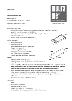
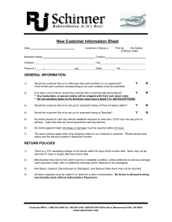
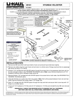
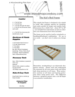
ASSEMBLY AND OPERATING MANUAL LTW SLIDE RAIL SYSTEM - Type PV Manufacturer: Phone: Fax: e-mail: homepage: LTW Tiefbauvertriebs GmbH Holter Weg 11 D – 41836 Hückelhoven-Brachelen +49 (0) 24 62 / 2009 0 +49 (0) 24 62 / 2009 15 [email protected] http:\ \ www.LTW-Shoring.com LTW Tiefbauvertriebs GmbH * Holter Weg 11 * D-41836 Hückelhoven-Brachelen 21.03.2014 page 1 ASSEMBLY AND OPERATING MANUAL LTW SLIDE RAIL SYSTEM - Type PV General Instructions Intended Use The Parallel Slide Rail System is available as EG-PV (Single Slide Rail System) for a maximum trench depths of ~3,80m and DG-PV (Double Slide Rail System) for maximum excavation depths of ~7,50m. Slide Rail Systems are being installed using the lowering and cut method (“dig and push”). The following regulations and rules have to be followed in their valid version: - Regulations of the BG-Fachausschuss Tiefbau (technical committee civil and underground engineering) - DIN 4124 Baugruben und Gräben (excavation pits and trenches) - DIN EN 13331 Teil 1 & 2 Grabenverbaugeräte (part 1 and 2 construction equipment) - Regeln für Sicherheit und Gesundheit bei der Arbeit (rules for safety and health during work) - Unfallverhütungsvorschriften / Arbeitsschutzvorschriften (regulations for the prevention of accidents and safety at work rules) Our shoring components have the GS-Sign „Certified Safety“. Please follow the instructions making use of our Slide rail systems. Lifting & Transportation The shoring may only be attached at the corresponding eyes and openings and/or lifting accessories. Lifting chains must be chosen to suit the weight being handled. To prevent the accidental detachment of the load use only load hooks with safety catches. The allowed tensile forces have to be kept in any cases. Transportation has to be carried out next to soil and unneeded oscillations have to be avoided. It is prohibited to stand within the pivoting range of the excavator or crane and beneath suspended loads. When handling and removing the shoring, watch out for overhead contact lines (power cables). A load operator must stand to the front of the excavator and be in eye contact with the machine operator. Measures to reduce hazards The safety of persons on site must be enhanced with the aid of signs, cones, warning tapes and/or safety staff specially deployed on site for this purpose. Neighbouring traffic flow has to be made possible by means of safety staff if needed. Personnel must wear protective clothing (helmet/safety shoes/gloves). The risk of instability as a consequence of wind loads when setting up or using the shoring must be considered. The shoring must be lowered onto level and firm ground. Where the ground is sloping or uneven, the shoring should be set up, if possible, at right angles to the slope. Maintenance & Repair Before use, all shoring components must be checked for their correct function. Faulty or deformed parts must be replaced in any case. Minor repairs can be carried out by the user, after consultation with LTW. There is no warranty on incorrectly performed repairs and the use of non-original parts. According to intenseness of use, the components should be painted with anticorrosion paint every two years. LTW Tiefbauvertriebs GmbH * Holter Weg 11 * D-41836 Hückelhoven-Brachelen 21.03.2014 page 2 ASSEMBLY AND OPERATING MANUAL LTW SLIDE RAIL SYSTEM - Type PV System view Single Slide Rail System - Type EG PV 1 2 B T Single Slide Rail Shoring Frame Base Plate Top Plate b bC t Pl t Tr Shoring Width Inner Working Width Plate Thickness Rail Thickness hC L LC LS Pipe Culvert Height Plate Length Pipe Culvert Length System Length LTW Tiefbauvertriebs GmbH * Holter Weg 11 * D-41836 Hückelhoven-Brachelen 21.03.2014 page 3 ASSEMBLY AND OPERATING MANUAL LTW SLIDE RAIL SYSTEM - Type PV System view Single Slide Rail System - Type EG PV U-Shoring Frame 1 2 B T Single Slide Rail U-Shoring Frame Base Plate Top Plate b bC t Pl t Tr Shoring Width Inner Working Width Plate Thickness Rail Thickness hC L LC LS Pipe Culvert Height Plate Length Pipe Culvert Length System Length LTW Tiefbauvertriebs GmbH * Holter Weg 11 * D-41836 Hückelhoven-Brachelen 21.03.2014 page 4 ASSEMBLY AND OPERATING MANUAL LTW SLIDE RAIL SYSTEM - Type PV System view Double Slide Rail System - Type DG PV 1 2 B T Double Slide Rail Shoring Frame Base Plate Top Plate b bC t Pl t Tr Shoring Width Inner Working Width Plate Thickness Rail Thickness hC L LC LS Pipe Culvert Height Plate Length Pipe Culvert Length System Length LTW Tiefbauvertriebs GmbH * Holter Weg 11 * D-41836 Hückelhoven-Brachelen 21.03.2014 page 5 ASSEMBLY AND OPERATING MANUAL LTW SLIDE RAIL SYSTEM - Type PV System view Double Slide Rail System - Type DG PV U-Shoring Frame 1 2 B T Double Slide Rail U-Shoring Frame Base Plate Top Plate b bC t Pl t Tr Shoring Width Inner Working Width Plate Thickness Rail Thickness hC L LC LS Pipe Culvert Height Plate Length Pipe Culvert Length System Length LTW Tiefbauvertriebs GmbH * Holter Weg 11 * D-41836 Hückelhoven-Brachelen 21.03.2014 page 6 ASSEMBLY AND OPERATING MANUAL LTW SLIDE RAIL SYSTEM - Type PV Technical Characteristics SLIDE RAIL SHORING PLATES Off-the-shelf, the Slide Rail Plates are designed - VSI -; i.g. Rails and Plates are flush inside (for use with in-situ ducts). On demand the plates can also be supplied - VSA -; i.g. Rails and plates are flush outside (for inner city shoring , allowing a straight blacktop cut.) Plates VS 100 Plate length L Plate height H Plate thickness t Pl Pipe culvert length LC Limit state design load ed Plate weight G PL [m] [m] [ mm ] [m] [ kN / m² ] [ kg ] 2,40 2,00 1,40 1,60 510 100 ~2,00 171,6 100 ~2,50 110,4 2,40 2,50 1,40 1,60 605 2,40 3,00 335 370 400 440 690 100 ~3,00 81,1 1,40 1,60 100 ~3,50 56,6 525 580 Plate length L Plate height H Plate thickness t Pl Pipe culvert length LC Limit state design load ed Plate weight G PL [m] [m] [ mm ] [m] [ kN / m² ] [ kg ] 1,40 1,60 2,40 3,50 450 500 805 Plates VS 120 2,40 4,00 1,40 1,60 1170 120 ~4,00 71,0 120 ~4,50 56,2 2,40 4,50 1,40 1,60 1305 2,40 5,00 1,40 1,60 745 835 830 930 1635 120 ~5,00 72,1 LTW Tiefbauvertriebs GmbH * Holter Weg 11 * D-41836 Hückelhoven-Brachelen 1020 1150 21.03.2014 page 7 ASSEMBLY AND OPERATING MANUAL LTW SLIDE RAIL SYSTEM - Type PV SLIDE RAILS Single Slide Rail - Type EG PV Description Rail length Rail thickness t Tr Limit state design moment Md Weight [m] [ mm ] [ kNm ] [ kg ] EG PV 4,00 177 338 495 Corner - EG 3,00 Corner - EG 3,50 Corner - EG 4,00 G Tr 310 218 147 355 400 Double Slide Rail - Type DG PV Description Rail length Rail thickness t Tr Limit state design moment Md Weight [m] [ mm ] [ kNm ] [ kg ] G Tr DG PV 4,80 1075 DG PV 6,00 DG PV 7,00 DG PV 7,50 Corner - DG 4,50 Corner - DG 5,00 Corner - DG 5,50 Corner - DG - A 2,00 236 Roller spacing Flange dimension minimum working width b C, min Weight [m] [ mm ] [m] [ kg ] EG LW 1,39 160 * 205 0,45 107 EG U-LW 1,25 300 * 480 0,82 404 DG LW 2,00 240 * 305 0,73 320 1020 1335 1555 325 1106 1780 715 305 363 780 840 322 315 Shoring Frame working for DG LW 2,80 DG U-LW 1,45 G LW 308 343 300 * 580 0,92 488 LTW Tiefbauvertriebs GmbH * Holter Weg 11 * D-41836 Hückelhoven-Brachelen 21.03.2014 page 8 ASSEMBLY AND OPERATING MANUAL LTW SLIDE RAIL SYSTEM - Type PV BRACE EXTENSIONS - EG PV Flange 160 * 205 - HEB 160 Screw Set M16*70 HV - Torque moment 250 Nm Brace Extension Working width bC Shoring width b Weight G [m] [m] [m] [ kg ] - 0,45 0,80 - 0,25 0,70 1,05 19 0,50 0,95 1,30 32 0,75 1,20 1,55 43 1,00 1,45 1,80 54 1,50 1,95 2,30 75 2,00 2,45 2,80 98 2,50 2,95 3,30 120 Flange 300 * 480 - HEB 360 Screw Set M30*105 HV - Torque moment 1650 Nm Brace Extension Working width bC Shoring width b Weight G [m] [m] [m] [ kg ] - 0,82 1,17 - 0,25 1,07 1,42 95 0,50 1,32 1,67 133 0,75 1,57 1,92 169 1,00 1,82 2,17 206 1,50 2,32 2,67 279 2,00 2,82 3,17 353 2,50 3,32 3,67 426 LTW Tiefbauvertriebs GmbH * Holter Weg 11 * D-41836 Hückelhoven-Brachelen 21.03.2014 page 9 ASSEMBLY AND OPERATING MANUAL LTW SLIDE RAIL SYSTEM - Type PV BRACE EXTENSIONS - DG PV DG PV - Flange 240 * 305 - HEB 240 Screw Set M24*85 HV - Torque moment 800 Nm Brace Working width bC Shoring width b Weight G [m] [m] [m] [ kg ] - 0,73 1,36 - 0,25 0,98 1,61 45 0,50 1,23 1,86 69 0,75 1,48 2,11 90 1,00 1,73 2,36 112 1,50 2,23 2,86 154 2,00 2,73 3,36 199 2,50 3,23 3,86 242 Extension DG PV - Flange 300 * 580 - HEB 450 Screw Set M30*105 HV - Torque moment 1650 Nm Brace Extension Working width bC Shoring width b Weight G [m] [m] [m] [ kg ] - 0,92 1,56 - 0,50 1,42 2,06 161 0,75 1,67 2,31 204 1,00 1,92 2,56 248 1,50 2,42 3,06 336 2,00 2,92 3,56 425 2,50 3,42 4,06 513 LTW Tiefbauvertriebs GmbH * Holter Weg 11 * D-41836 Hückelhoven-Brachelen 21.03.2014 page 10 ASSEMBLY AND OPERATING MANUAL LTW SLIDE RAIL SYSTEM - Type PV Accessories Description Dimension specified use for Weight [kg] locking bolt 50 * 114 locking feature for shoring frame 2,1 bolt 40 * 128 connection between Base and Extension Plates 1,4 bolt 40 * 198 connection Base and Extension Corner Slide Rails 2,2 locking clip [R] 6 locking clip for connecting bolt at plates 0,1 hexagon screw M16*70 HV hex-nut M16 HV washer for M16 0,02 hexagon screw M24*85 HV 0,57 hex-nut M24 HV washer für M24 hexagon screw M30*105 HV hex-nut M30 HV washer für M30 protection rail L = 1800 for Plate length 2,00m 151 protection rail L = 2300 for Plate length 2,50m 188 protection rail L = 2500 for Plate length 3,00m 203 protection rail L = 3300 for Plate length 3,50m 264 protection rail L = 3800 for Plate length 4,00m 304 protection rail L = 4300 for Plate length 4,50m 341 protection rail L = 4800 for Plate length 5,00m 378 for strut free pits (long pipes etc.) 220 0,14 for flange 160 * 205 EG PV for flange 240 * 305 DG PV 0,04 0,17 0,03 clamping device for flange 300 * 480 EG PV & for flange 300 * 580 DG PV 0,90 0,20 0,05 Tensile Forces lifting eyes at the rail head R d = 226 kN lifting eyes at the plate head R d = 229 kN bottom eyes at the plate Rd = 47 kN LTW Tiefbauvertriebs GmbH * Holter Weg 11 * D-41836 Hückelhoven-Brachelen 21.03.2014 page 11 ASSEMBLY AND OPERATING MANUAL LTW SLIDE RAIL SYSTEM - Type PV Assembly Instruction Slide Rail Frame place the Slide Rails with the guiding profile upwards onto a flat and firm ground Insert the shoring frame from the top, position the locking bolt 50*114mm above the frame in the designated position No. 2 and in the lowest one, and rotate the bolts by 180° in order to secure them. Put down oppositely the pre-assembled Slide Rails (according to the trench width required). Align the Brace Extensions in between the Slide Rails and flange each with six screw sets. put one washer under the screw head and one under the nut. Turn the screws dynamometric key. LTW Tiefbauvertriebs GmbH * Holter Weg 11 * D-41836 Hückelhoven-Brachelen crosswise 21.03.2014 with a page 12 ASSEMBLY AND OPERATING MANUAL LTW SLIDE RAIL SYSTEM - Type PV Installation Instr. To protect the shoring plates and ensure a long life cycle we recommend the use of protection rails. Pre-Excavation max. 1.25 m and not more than one shoring length. In principle the pre-excavation complies with the type of soil and safety regulations. Connect the lifting hocks to the first Base Panel, place it into the pre-excavated trench, push in and secure it. Pick up the pre-assembled Slide Rail Frame with an appropriate lifting device, raise it over the Base panel and insert the outer guidance over the side part (TSection) of the Panel. Press the Slide Rail Frame carefully into the ground. Insert the second shoring plate in the outer guidance of the other Slide Rail, align it diagonal and press it carefully in the ground. Ropes can be connected to the eyes at the cutting edge in order to provide better handling of the plates. Now the second pre-assembled Slide Rail Frame is guided over the outer guidance and pushed into the soil. Fill the gap between the trench walls and the inserted shoring unit ! Excavate about further 0.5 m in between the plates press in by turns the slide rails, the Shoring Frame and the Plates. For security reasons it is not allowed to push on the Brace Extensions. At this stage the trench must not be entered ! As smaller the steps of excavation are carried out, as better for the shoring. Do not press more than 50 cm on one side. When the top of the externally guided plate has reached the top ground surface, the system will be extended by using a top plate (outer guidance) or by mounting another Base Plate in the inner guidance. LTW Tiefbauvertriebs GmbH * Holter Weg 11 * D-41836 Hückelhoven-Brachelen 21.03.2014 page 13 ASSEMBLY AND OPERATING MANUAL LTW SLIDE RAIL SYSTEM - Type PV Connect the Base and Extension Plates with the Connecting Bolts 40*128mm and the [R] locking clips. Excavate about further 0.5 m in between the plates press in by turns the slide rails, the Shoring Frame and the Plates. The step-by-step installation has to be continued, until the trench has reached the desired trench depth. The top edge of the shoring must overtop the surrounding terrain by at least 5 cm. The Slide Rail Frame can now be positioned to the required strut clearance height. Position the locking bolt 50*114mm under the Slide Rail Frame and rotate by 180° in order to secure. This is important to avoid an inadvertently sliding of the Slide Rail Frame. Installation of the next shoring unit Once the foregoing section has been installed to full depth, it can be started with the next section. The installation is effected as described before - with the installation of the Pates in the outer guidance. The Plate distance has to be checked for every new shoring bay! LTW Tiefbauvertriebs GmbH * Holter Weg 11 * D-41836 Hückelhoven-Brachelen 21.03.2014 page 14 ASSEMBLY AND OPERATING MANUAL LTW SLIDE RAIL SYSTEM - Type PV Re-Installation After completion of the Pipe laying the re-installation of the shoring can be effected. According to compacting possibilities bring in 0,50m filling material. Start lifting the inner plates by the filled height. Finally compact the backfill. As smaller the lifting steps are carried out, as better for the shoring. Do not lift more than 0,50m on one side. Repeat this procedure as described until the shoring can be lifted out of the trench. You should only use the designated lifting eyes for lifting the shoring components. It is not allowed to lift at the Brace Extensions! It is prohibited to stand within the pivoting range of the excavator or crane and beneath suspended loads. LTW Tiefbauvertriebs GmbH * Holter Weg 11 * D-41836 Hückelhoven-Brachelen 21.03.2014 page 15 ASSEMBLY AND OPERATING MANUAL LTW SLIDE RAIL SYSTEM - Type PV Pits Corner Single Slide Rails 1 B Corner slide rail EG Base Plate T b Top Plate Shoring Width bC L Inner Working Width Plate Length LTW Tiefbauvertriebs GmbH * Holter Weg 11 * D-41836 Hückelhoven-Brachelen 21.03.2014 page 16 ASSEMBLY AND OPERATING MANUAL LTW SLIDE RAIL SYSTEM - Type PV Pits Corner Double Slide Rails 1 B Corner slide rail DG Base Plate T b Top Plate Shoring Width bC L Inner Working Width Plate Length LTW Tiefbauvertriebs GmbH * Holter Weg 11 * D-41836 Hückelhoven-Brachelen 21.03.2014 page 17 ASSEMBLY AND OPERATING MANUAL LTW SLIDE RAIL SYSTEM - Type PV Installation Instruction Pre-Excavation of max. 1,25m and approx. 10cm wider than the pit will be. In principle the pre-excavation complies with the type of soil and safety regulations. Connect the lifting hocks to the first Base Panel, place it into the pre-excavated trench, push in and secure it. Pick up the 1. Corner Slide Rail with an appropriate lifting device, raise it over the Base panel and insert the outer guidance over the side part (T-Section) of the Panel. Press the Slide Rail Frame carefully into the ground. At this stage the trench must not be entered! Mount the second plate in the free outer guidance of the Corner Slide Rail and align rectangular. The 2. Corner Slide Rail is now guided with the outer guidance over the side part (T-Section) of the already installed Panel. The further installation is effected as described before, until all 4 Plates had been installed. LTW Tiefbauvertriebs GmbH * Holter Weg 11 * D-41836 Hückelhoven-Brachelen 21.03.2014 page 18 ASSEMBLY AND OPERATING MANUAL LTW SLIDE RAIL SYSTEM - Type PV The 4. Corner Slide Rail is now guided over the two free side parts (T-Sections) of the plates. The perfect distances between the two free side parts should be ~10cm using the Corner Single Slide Rail System and ~32cm using the Corner Double Slide Rail System. Pre-excavate about another 50cm and push in Rails and Plates by turn. Fill the gap between the trench walls and the inserted shoring ! To protect the shoring plates and ensure a long life cycle we recommend the use of protection rails. When the top of the externally guided plate has reached the top ground surface, the system will be extended by using a top plate (outer guidance) or by mounting another Base Plate in the inner guidance. Connect the Base and Extension Plates with the Connecting Bolts 40*128mm and the [R] locking clips. The step-by-step installation has to be continued, until the trench has reached the desired trench depth. For trench depths greater than the length of the Base Rail, extension Rails have to be used. Base and Extension Rails are connected with the Connection Bolt 40*198mm and the [R] locking clip. The top edge of the shoring must overtop the surrounding terrain by at least 5cm. LTW Tiefbauvertriebs GmbH * Holter Weg 11 * D-41836 Hückelhoven-Brachelen 21.03.2014 page 19 ASSEMBLY AND OPERATING MANUAL LTW SLIDE RAIL SYSTEM - Type PV 2 Bay Pit Corner Slide Rails and & DG PV 1 2 Eckträger DG Gleitschienen Träger 3 B Laufwagen Grundplatte LTW Tiefbauvertriebs GmbH * Holter Weg 11 * D-41836 Hückelhoven-Brachelen 21.03.2014 page 20 ASSEMBLY AND OPERATING MANUAL LTW SLIDE RAIL SYSTEM - Type PV Clamping Device - Strut free 2 Bay Pit Corner Slide Rails and & DG PV 1 2 3 Clamping Device upper waler H-Beam bottom support or concrete floor T LR trench depth Rail Length = T + 1,20 m LTW Tiefbauvertriebs GmbH * Holter Weg 11 * D-41836 Hückelhoven-Brachelen 21.03.2014 page 21 ASSEMBLY AND OPERATING MANUAL LTW SLIDE RAIL SYSTEM - Type PV Technical parameters Clamping Device consisting of: Description Qty. Weight [ kg/pce.] Socket 2 50,9 End Plate 1 94,2 threaded rod 4 4,5 hex-nut 8 0,5 washer 8 0,1 complete kid 1 220 The clamping device engages behind the outer rail guidance and clamps the outside horizontal upper waler (e.g. HEB 500). It creates a loadcarrying connection which enables the forces that arise being discharged into the outer Slide Rails. LTW Tiefbauvertriebs GmbH * Holter Weg 11 * D-41836 Hückelhoven-Brachelen 21.03.2014 page 22 ASSEMBLY AND OPERATING MANUAL LTW SLIDE RAIL SYSTEM - Type PV Installation Instruction Installation of the Slide Rail System as described before. The Shoring plates must reach the top ground surface. The Slide Rail Frame must be braced in the trench bottom, (bottom support), e.g. by means of a HEB Waler or a Concrete Slab. The dimensioning of the waler acts in accordance with the statical requirements. Pre-assemble the sockets with the threaded rods, hex-nuts and washers. Move the first socket over the outside rail guidance and put down on the top ground surface. Put the waler behind the Slide Rails on approx. 10cm thick wood pieces. Move the second pre-assembled socket over the outside guidance of the Slide Rail and put down on the top of the waler. Take the End Plate and fix it to the threaded rods, and fasten the bolts securely with nuts and washer. Now the Slide Rails Frame can be removed. Rotate the top locking bolt 50*114mm of the Slide Rail and remove him. LTW Tiefbauvertriebs GmbH * Holter Weg 11 * D-41836 Hückelhoven-Brachelen 21.03.2014 page 23


© Copyright 2026