
B . C
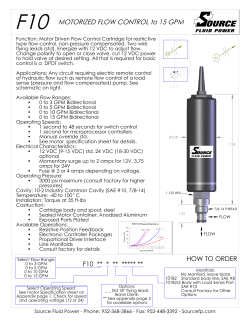
B.C. SPRINKLER IRRIGATION MANUAL Chapter 5 Editor Ted W. van der Gulik, P.Eng. Senior Engineer Authors Stephanie Tam, P.Eng. Water Management Engineer Andrew Petersen, P.Ag. Regional Resource Specialist Prepared and Web Published by Ministry of Agriculture 2014 ISSUE LIMITATION OF LIABILITY AND USER’S RESPONSIBILITY The primary purpose of this manual is to provide irrigation professionals and consultants with a methodology to properly design an agricultural irrigation system. This manual is also used as the reference material for the Irrigation Industry Association’s agriculture sprinkler irrigation certification program. While every effort has been made to ensure the accuracy and completeness of these materials, additional materials may be required to complete more advanced design for some systems. Advice of appropriate professionals and experts may assist in completing designs that are not adequately convered in this manual. All information in this publication and related materials are provided entirely “as is” and no representations, warranties or conditions, either expressed or implied, are made in connection with your use of, or reliance upon, this information. This information is provided to you as the user entirely at your risk. The British Columbia Ministry of Agriculture and the Irrigation Industry Association of British Columbia, their Directors, agents, employees, or contractors will not be liable for any claims, damages or losses of any kind whatsoever arising out of the use of or reliance upon this information. 5 SPRINKLER SYSTEM DESIGN When using the term "sprinkler irrigation", reference to stationary irrigation systems with flow rates ranging from 1/2 to 12 gpm per sprinkler head is usually intended. The selection of an appropriate sprinkler and nozzle combination requires knowledge on system types, sprinkler spacing, operating pressures and soil conditions. 5.1 Sprinkler Nozzle, Pressure and Spacing Selection Efficient irrigation system design requires the selection and matching of the sprinkler equipment and spacing to the crop, soil and field shape. An appropriate sprinkler spacing is determined by the type of nozzle used and the operating pressure selected. Every sprinkler-nozzle combination has a specific operating pressure range. Too much pressure will disperse the water stream into a very fine spray resulting in increased evaporation losses or poor distribution. Wind effects on sprinkler distribution patterns are more pronounced on fine droplet sizes. Conversely too little pressure will not sufficiently break up the water stream and may result in puddling, runoff, poor distribution patterns and crop damage. Sprinkler irrigation system spacings are usually denoted by the sprinkler spacing along the lateral and lateral spacing along the mainline. Therefore, 40 x 60 denotes a 40 ft sprinkler spacing and a 60 ft lateral spacing. The actual layout of the system may be square or rectangular. See Figure 5.1. Handlines and wheellines usually accommodate a square or rectangular spacing while solid set systems can be triangular, rectangular or square. Triangular spacings may increase application efficiency for undertree systems in orchard plantings. Triangular spacings allow the designer to minimize the interference effect of tree trunks and lower branches on application uniformity. In situations where there is a predominant wind direction, the irrigation system should be designed so that the sprinkler lateral is perpendicular to the wind. A closer sprinkler spacing than normal may be required for these situations. The distribution by a sprinkler irrigation system can be checked by determining the coefficient of uniformity. Appendix E explains this term and how it can be calculated. Chapter 5 Sprinkler System Design 53 Figure 5.1 Sprinkler Layouts The maximum spacing of a sprinkler system is determined by the wetted diameter of the sprinkler and the wind speed. The wetted diameter of a sprinkler is a function of nozzle size and operating pressure. Sprinkler manufacturer's charts will provide wetted diameter information. Sprinklers and laterals should be spaced no futher than the maximum percentage of wetted diameter based on various wind speeds as shown in Table 5.1. Lateral lines are often spaced slightly further apart than 50% of the wetted diameter but this is then made up by a sprinker spacing along the lateral that is slightly closer. Table 5.1 Sprinkler Spacing Recommendations Wind Speed Spacing as a Percentage of Wetted Diameter Up to 6.5 km/hr 60% 6.5 – 13 km/hr 50% Over 13 km/hr 40% To obtain good uniformity, sprinkler systems must provide sufficient overlap. The minimum coefficient of uniformity should not be less than 80%. Following the recommended spacings as shown in Table 5.1 should allow the irrigation system to achieve a coefficient of uniformity of 80% under normal operating conditions. 54 B.C. Sprinkler Irrigation Manual Application Efficiency (AE) Application efficiency is an indication of the percentage of water applied by the irrigation system that is actually available to the crop. Lower efficiencies mean more water is lost during the application process to evaporation, wind drift or runoff and is not available to the crop. Efficiencies of irrigation systems can vary due to wind, operating pressure, sprinkler trajectory, time of day, and hot or cool weather. The efficiency can also be affected by the design, operation and maintenance of the irrigation system. Typical application efficiencies can be found in Table 3.1 in Chapter 3. Irrigation Interval (II) Irrigation Interval (II) is the number of days that it takes the irrigation laterals to cover the field. This is calculated by determining the number of lateral settings in a field and dividing this by the number of sets operated each day (Equation 5.1). Equation 5.1 Irrigation Interval (II) II = where II = Number of Sets in Field Number of Sets per Day Irrigation Interval (days) Net Water Required (NWR) Net Water Required (NWR) is the amount of water required by the crop to be able to sustain optimum growth over the irrigation interval. It is determined by multiplying the daily evapotranspiration (ET) rate by the irrigation interval (II) (Equation 5.2). Equation 5.2 Net Water Required (NWR) NWR = II × ET where NWR = II = ET = Net Water Required (in) Irrigation Interval (days) Reference evapotranspiration (ET) (in/day) Chapter 5 Sprinkler System Design 55 Gross Water Required (GWR) Gross Water Required (GWR) is the amount of water that must be applied by the irrigation system, taking into account application efficiency, to ensure that the crop NWR is applied as shown in Equation 5.3. Equation 5.3 Gross Water Required (GWR) GWR = where GWR = NWR = AE = NWR AE Gross Water Required (in) Net Water Required (in) Application Efficiency (percent as a decimal) Set Time The irrigation set time is the length of time that the irrigation system is operating at one set. Set times of 11.5 or 23.5 hours are usually selected for handmove and wheelmove systems to allow time to move the system to the next set. Solid set systems usually have set times of 12 or 24 hours as the next lateral can be turned on very quickly. If the system is automated set times can be lowered to 6 hours or less to accommodate low MSWD to ensure soil storage is not exceeded. The set time is at the discretion of the operator but the time selected should fit in with the system application rate and soil water storage calculations. Application Rate (AR) The irrigation system application rate is the amount of water applied by the irrigation system during a given period of time. For agricultural irrigation, the irrigation system must be able to apply the Gross Water Required (GWR) during the set time that has been selected. Equation 5.4 determines the desired application rate of the irrigation system. Equation 5.4 Application Rate (AR) AR = where AR = GWR = Set Time = GWR Set Time Irrigation system application rate (in/hr) Gross water required (in) Set time (hr) Once the application rate of the system has been determined the desired flow rate of the sprinklers can be determined using Equation 5.5. The flow rate is calculated using the application rate and the sprinkler and lateral spacing. The sprinkler spacing is the distance between two adjacent sprinklers along a lateral. A lateral spacing is the distance between laterals or the distance the lateral is moved from one set to the next across the field. 56 B.C. Sprinkler Irrigation Manual Equation 5.5. Calculated Sprinkler Flow Rate (Q) Q= where Q= AR = S1 = S2 = AR × S1 × S 2 96.3 Sprinkler flow rate (US gpm) System application rate (in/hr) Sprinkler spacing along lateral (ft) Lateral spacing (ft) The sprinkler flow rate can be used to select a nozzle and operating pressure that will match the desired application rate of the irrigation system. Tables 5.2 to 5.8 indicate the application rate for various nozzle-pressure combinations and standard sprinkler spacings used for handmove and wheelmove systems. These tables can also be used to calculate the lateral pipe sizes required for aluminum laterals used in handmove and wheelmove systems. The maximum number of sprinklers per lateral when on level ground is calculated using a total allowable lateral friction loss of 20% of the sprinkler operating pressure. For example, a lateral operating at 50 psi should not have a friction loss exceeding 10 psi. Tables 5.2 to 5.8 indicate the lateral pipe sizing requirements as a percentage of total lateral length for various sprinkler flow rates and number of sprinklers operating. These percentages are based on the maximum pressure variation in the lateral not exceeding 20%. The pressure required at the start of the lateral is also shown. If there is an elevation difference along the lateral this should be accommodated in the calculation. For example, Table 5.2 indicates that a handmove system using 21 sprinklers with a flow rate of 4.66 US gpm on a 30 ft x 30 ft spacing must use a lateral line that consists of 50% 3-inch aluminum pipe and 50% 2-inch aluminum pipe. Example 5.1 for a wheelmove system in Armstrong shows how irrigation design parameters are calculated and how to use Tables 5.2 to 5.8. Laterals that are operating up or down a slope may require flow control valves to maintain distribution uniformity. See Section 5.2 of this chapter. Examples 5.2 and 5.3 show how to determine the irrigation system parameters for a solid set sprinkler and micro sprinkler system. The sprinkler nozzle charts in Table 5.9 and 5.10 provide information for most nozzle and pressure combinations that are common on agricultural systems. Manufacturer’s charts can be used to obtain more accurate information. Application Rate Check Once a nozzle and operating pressure have been selected, the actual sprinkler flow rate should be checked from manufacturer’s charts. The actual flow rate may be slightly different from the tables provided in this manual depending on the sprinkler model and nozzle chosen. The application rate of the irrigation system should then be recalculated to Chapter 5 Sprinkler System Design 57 ensure that it does not exceed the maximum allowed based on the soil infiltration rate. The irrigation system application rate should not exceed the maximum application rates that are allowed by the soil as shown in Table 4.4. The application rate of the sprinkler system should be checked again to determine if it is the same as the value calculated in Equation 5.4. If the sprinkler flow rate has changed from what was determined in Equation 5.5 the application rate will have changed. Equation 5.6 can be used to do a verification of the irrigation system application rate. Equation 5.6. Calculated Application Rate (AR) AR = where Q= AR = S1 = S2 = 96.3 × Q S1 × S 2 Sprinkler flow rate (US gpm) System application rate (in/hr) Sprinkler spacing along lateral (ft) Lateral spacing (ft) Example 5.1 Wheelmove System Design in Armstrong Question: A farmer near Armstrong intends to grow alfalfa on a deep sandy loam soil. The farm consists of three areas that are all 1,320 ft x 1,320 ft each. See Figure 5.2. For a wheelmove system, what nozzle size, spacing, pressure, sprinkler flow rate, lateral size and irrigation interval will be required? Information: alfalfa 1 Crop type Farm location Armstrong 2 1,320 3 Field width 1,320 4 Field length 3.0 5 Maximum soil water deficit (MSWD) (Box 8, Example 4.1) 0.21 6 Peak evapotranspiration (ET) (Box 3, Example 4.3 or Table 4.5) 14 7 Maximum irrigation interval (Max II) (Box 8, Example 4.3) 0.72 8 Application efficiency (Table 3.1) Soil type Sandy loam 9 0.45 10 Maximum application rate (Max AR)(Table 4.4) ft ft in in/day days in/hr The normal practice is to select an 11.5 hour set time which allows two moves per day and ½ hour moving time per set. 11.5 11 hr Set time 2 12 sets/day Number of sets per day A sprinkler spacing of 40 ft x 60 ft is normally chosen for a wheelmove system. 40 13 ft Sprinkler spacing 60 14 ft Lateral spacing 58 B.C. Sprinkler Irrigation Manual Figure 5.2 Chapter 5 Sprinkler System Design 59 Calculation: Number of Sprinklers = = = Number of = Sets in Field = = Field Width Sprinkler Spacing 1,320 3 ft 40 13 ft 33 15 sprinklers per lateral Field Length Lateral Spacing 1,320 4 ft 60 14 ft 22 16 sets Equation 5.1 II = = = Number of Sets in Field Number of Sets per Day 22 16 sets 2 12 sets/day 11 17 days Determine the net water required (NWR). Equation 5.2 NWR = II x ET = 11 17 days x = 2.3 18 in Determine the gross water required (GWR). Equation 5.3 GWR = = = NWR AE 2.3 18 0.72 8 3.2 19 in in Determine the application rate (AR). Equation 5.4 AR = = = 60 B.C. Sprinkler Irrigation Manual GWR Set Time 3.2 19 in 11.5 11 hr 0.28 20 in/hr 0.21 6 in/day Determine the sprinkler flow rate. 0.28 For a wheelmove system with a 40’ x 60’ spacing, and an AR of the following can be extracted from Table 5.6: 21 in/hr, Table 5.6 Sprinkler Nozzle Specifications – 40’ x 60’ Spacing Nozzle [in] Nozzle Pressure [psi] Pressure at Start of Lateral [psi] Flow Rate [gpm] Application Rate [in/hr] 11/64 x 3/32 40 46 7.03 0.28 Sprinkler Q = 7.03 21 Maximum No. of Sprinklers on Aluminum Lateral when on Level Ground 100% 75% 2” 2” 25% 3” 10 50% 2” 100% 75% 3” 50% 3” 3” 25% 4” 12 15 20 23 50% 3” 100% 50% 4” 4” 26 33 gpm Equation 5.6 AR = 96.3 x Q S1 x S2 96.3 x = = Max. Lateral Length = 40 13 ft x 0.28 22 in/hr 7.03 21 gpm 60 14 ft No. of Sprinklers per lateral x Sprinkler Spacing = 33 15 sprinklers x = 1,320 23 ft 40 13 ft Answer: Since: 1). the Irrigation Interval of Maximum Irrigation Interval of 0.28 2). the AR of 3). the number of sprinklers is 22 11 17 days is less than 14 7 days, in/hr is less than the Max AR of 33 15 0.45 10 in/hr, sprinklers, a 4” wheelmove system is adequate, and all the design parameters chosen are sufficient. The following design criteria can now be used to determine the layout of the irrigation system: The sprinkler system consists of 11/64" x 3/32" nozzles operating at 40 psi with a flow rate of 7.0 US gpm. On a 40' x 60' spacing and an 11.5 hr set time, the gross applied is 3.2 inches. The net amount applied to the crop at an application efficiency of 72% is 2.3 inches, which is sufficient for an 11-day irrigation interval at an ET rate of 0.21 in/day. A 1,320 ft lateral will require 33 sprinklers, operating at 7.0 US gpm each, for a lateral flow rate of 231 US gpm. The lateral will consist of 4" aluminium pipe with a supply pressure of 46 psi at the beginning of the lateral to ensure proper operation of all sprinklers. Figure 5.2 outlines the complete layout of this wheelmove irrigation system. Chapter 5 Sprinkler System Design 61 Example 5.2 Undertree Solid Set System Design in Osoyoos Question: The farmer in Osoyoos Irrigation District is planting apples on a 7.5 ft x 15 ft spacing. The 10 acre field (roughly 750 ft x 600 ft) will have 50 rows of apples 600 feet long. For an undertree solid set sprinkler system, what sprinkler nozzle size, spacing, pressure, flow rate and interval will be required? Information: Apples Crop type Farm location Osoyoos ID 8 Water allotment 10.3 Irrigated area 50 Number of tree rows 600 Tree row length 750 Field length Tree spacing 7.5 x 15 2.1 Maximum soil water deficit (MSWD) (Box 8, Example 4.2) 0.28 Peak evapotranspiration (ET) (Table 4.5) 0.75 Application efficiency (AE) (Table 3.1) Loam Soil type 0.35 Maximum application rate (Max AR)(Table 4.4) 1 2 3 4 5 6 7 8 9 10 11 12 13 gpm/acre acres rows ft ft ft in in/day in/hr The farmer will operate the solid set system on a 12-hour set. Set time Number of sets per day 12 2 14 15 hr sets/day Since the apple trees are 7.5 feet apart and a low angle impact sprinkler has a radius of 22 to 33 feet, select spacings as follows: Sprinkler spacing, S1 Lateral spacing, S2 Calculation: Number of Laterals = = = Field Length Lateral Spacing 750 7 ft 30 17 ft 25 18 laterals Run 2 laterals per set, so there are 62 B.C. Sprinkler Irrigation Manual 13 19 sets total 30 30 16 17 ft ft Figure 5.3 Chapter 5 Sprinkler System Design 63 Equation 4.3 Max II = = = MSWD ET 2.1 9 in 0.28 10 in/day 7.5 20 days Equation 5.1 II = = = Total Number of Sets Number of Sets per Day 13 19 sets 2 15 sets/day 6.5 21 days less than Max II of 7.5 20 days For simplicity of operating the system the designer selects a 7 day irrigation interval. Now determine the net and gross water required. Equation 5.2 NWR = II x ET = 7.0 21 days x = 2.0 22 in 2.0 22 in 0.75 11 2.67 23 0.28 10 in/day Equation 5.3 GWR NWR AE = = = in Determine the application rate. Equation 5.4 AR = = = GWR Set Time 2.67 23 in 12 13 hr 0.22 24 in/hr: less than Max AR of 0.35 13 Determine the sprinkler flow rate. Equation 5.5 AR x S1 x S2 Q = 96.3 = 0.22 24 in/hr x 30 16 96.3 = 64 B.C. Sprinkler Irrigation Manual 2.07 25 US gpm ft x 30 17 ft in/hr Determine the maximum number of sprinkler operating at one time. Farm Water Allocation Max Number of Sprinkler = = 8 3 US gpm/acre x = 80 26 US gpm 10.3 4 acres Farm Water Allocation = = = # of Sprinklers Req’d Water Allotment x Irrigated Area = = = No. of Sprinklers 80 26 US gpm 2.07 25 US gpm/sprinkler 38 27 sprinkler Row Length Sprinkler Spacing 570 6 ft 30 16 ft 19 28 sprinklers Operate 2 laterals per set. Checking the plan in Figure 5.3 shows 19 sprinklers per lateral line. Operating two lines at one time will be 38 sprinklers which will match the allowable amount from the irrigation district. 38 29 sprinkler From Table 5.10 select a 11 degree trajectory sprinkler with a 7/64 nozzle operating at 35 psi. The nozzle flow rate is 2.07 US gpm and the wetted radius is 31 ft (wetted diameter 62 ft). Sprinkler Q = 2.07 31 US gpm Equation 5.6 AR = 96.3 x Q S1 x S2 2.07 96.3 x = = 31 US gpm 30 16 ft x 30 0.22 32 in/hr less than Max AR of 17 ft 0.35 13 in/hr Answer: 1) 7 Since the Irrigation Interval of 7.5 Max Irrigation Interval of 2). Since the AR of 0.22 32 22 21 days is less than days, in/hr is less than the Max AR of 0.35 13 Chapter 5 Sprinkler System Design in/hr, 65 the design parameters chosen are sufficient. The following design criteria can now be used to determine the layout of the irrigation system: The sprinkler system consists of 7/64 nozzles operating at 35 psi with a flow rate of 2.07 US gpm. On a 30' x 30' spacing and a 12-hr set time the gross applied is 2.64 inches. The net amount applied to the crop at an application efficiency of 75% is 1.98 inches, which is sufficient for a 7 day irrigation interval at an ET rate of 0.28 in/day. A 600 ft lateral will require 19 sprinklers, allowing for headlands, operating at 2.07 US gpm each, for a lateral flow rate of 39.3 USgpm. The system will be running 2 laterals per set for a total flow rate of 80 USgpm. This flow rate is within the irrigation district allotment. The lateral would be split in the middle to reduce pipe size. There will be a total of 13 sets in the system which indicates that the actual irrigation interval is 6.5 days. Figure 5.3 outlines the complete layout of the solid set undertree irrigation system. Helpful Tips – Solid Set Sprinkler System Design When obtaining water from an irrigation district, the irrigation design should maximize the flow rate that is provided by the water purveyor. Maximizing the water purveyor flow rate allows the farmer more options with respect to system operation and management. The calculation process provided in Example 5.2 ensures that the design uses the maximum number of sprinklers per lateral allowed within the allowed system flow rate. Also the lateral set times used add up to 24 hours per day, maximizing the time available. Also, it is important to fill the crop’s soil storage capacity to reduce evaporation losses and to encourage deeper root growth. 66 B.C. Sprinkler Irrigation Manual Example 5.3 Microsprinkler System Design in Osoyoos Question: The same farmer in Osoyoos is also interested in a micro-sprinkler system. For a microsprinkler system, what sprinkler nozzle size, spacing, pressure, flow rate and interval will be required? Information: Apples Crop type Farm location Osoyoos ID 8 Water allotment 10.3 Irrigated area 50 Number of tree rows 600 Tree row length 750 Field length Tree spacing 7.5 x 15 2.1 Maximum soil water deficit (MSWD) (Box 8, Example 4.2) 0.28 Peak evapotranspiration (ET) (Table 4.5) 0.80 Application efficiency (AE) (Table 3.1) Loam Soil type 0.35 Maximum application rate (Max AR)(Table 4.4) 1 2 3 4 5 6 7 8 9 10 11 12 13 gpm/acre acres rows ft ft ft in in/day in/hr The farmer will operate the system at a 12-hour set. Set time Number of sets per day 8 3 14 15 hr sets/day Since the apple trees are 7.5 feet apart and the rows are 15 ft apart, select microsprinkler spacings as follows: Sprinkler spacing, S1 Lateral spacing, S2 15 15 16 17 ft ft Calculation: Number of Laterals = = = Field Length Lateral Spacing 750 7 ft 15 17 ft 50 18 laterals Run 3 laterals per set, so there are 17 19 sets total Chapter 5 Sprinkler System Design 67 Figure 5.4 68 B.C. Sprinkler Irrigation Manual Equation 4.3 Max II = = = MSWD ET 2.1 9 in 0.28 10 in/day 7.5 20 days Equation 5.1 II = = = Total Number of Sets Number of Sets per Day 17 19 sets 3 15 sets/day 5.7 21 days less than Max II of 7.5 20 days For simplicity of operating the system the designer selects a 6 day irrigation interval. Next determine the net and gross water required. Equation 5.2 NWR = II x ET = 6 21 days x = 1.68 22 in 0.28 10 in/day Equation 5.3 GWR NWR AE = = = 1.68 22 0.80 11 2.1 23 in in Determine the application rate. Equation 5.4 AR = = = GWR Set Time 2.1 24 in 8 13 hr 0.26 25 in/hr: less than Max AR of 0.35 13 in/hr Determine the sprinkler flow rate. Equation 5.5 AR x S1 x S2 Q = 96.3 = 0.26 25 in/hr x 15 16 ft x 15 17 ft 96.3 = 0.61 26 US gpm Chapter 5 Sprinkler System Design 69 Determine the maximum number of sprinkler operating at one time. Farm Water Allocation = = 8 3 US gpm/acre x = 80 27 US gpm Max Number = of Sprinkler = = # of Sprinklers Req’d Water Allotment x Irrigated Area = = = = 80 27 US gpm 0.61 18 US gpm/sprinkler 131 28 sprinkler acres Row Length Sprinkler Spacing 585 6 ft 15 16 ft 39 29 sprinklers 117 30 sprinklers Farm Water Allocation No. of Sprinklers 80 27 US gpm 117 18 sprinklers = 0.68 28 US gpm/sprinkler = 41 31 US gph/sprinkler = 4 Farm Water Allocation No. of Sprinklers Run 3 laterals per set the number of sprinkler per set is Maximum Sprinkler Q 10 From Table 5.11, select a 0.071” (gray) micro-sprinkler with a nozzle flow rate of 39 gph (0.65 gpm) operating at 20 psi. The nozzle will produce a wetted diameter of 34 ft. Sprinkler Q = 0.65 32 US gpm Equation 5.6 AR = 96.3 x Q S1 x S2 0.65 96.3 x = = 32 15 US gpm 15 16 ft x 0.28 33 in/hr less than Max AR of 17 ft 0.35 Determine if the MSWD is exceeded. Equation 5.4 GWR = 70 AR x Set Time = 0.28 33 in/hr x = 2.24 34 in B.C. Sprinkler Irrigation Manual 8 13 hr 13 in/hr Equation 5.3 NWR = GWR x AE = 2.24 34 in x 0.80 = 1.8 35 in is less than or equal to MSWD 11 2.1 9 in Answer: Since 1). the Irrigation Interval of Max Irrigation Interval of 2). the AR of 3). the NWR of 6 21 days is less than 7.5 20 days, 0.28 33 in/hr is less than the Max AR of 0.35 13 in/hr, 1.8 35 in is less than/equal to MSWD 2.1 13 in. The design parameters chosen are sufficient. The following design criteria can now be used to determine the layout of the irrigation system: The sprinkler system consists of 0.071” (gray) nozzles operating at 20 psi with a flow rate of 39 gph (0.65 gpm). On a 15' x 15' spacing and a 8 hr set time the gross amount applied is 2.24 inches. The net amount applied to the crop at an application efficiency of 80% is 1.8 inches, which is sufficient for a 6-day irrigation interval at an ET rate of 0.28 in/day. A 600 ft lateral will require 39 sprinklers, operating at 39 gph (0.65 gpm) each, for a total lateral flow rate of 25 USgpm. Running 3 laterals at a time will give a flow rate of 75 USgpm. This flow rate is within the irrigation district allotment. There will be a total of 17 sets in the system. Figure 5.4 outlines the complete layout of the microsprinkler irrigation system. Helpful Tips – Irrigation Design Parameters The irrigation design plans shown in chapters 5 are also provided in Appendix C with the corresponding design parameters shown on the adjacent page. The design parameter summary is useful for evaluating the irrigation system design and performance characteristics. This information should be included with every irrigation system plan. Helpful Tips – Lateral Friction Loss Calculations - Tables 5.2 – 5.8 The pipe sizes for aluminum pipe indicated in Table 5.2 to 5.8 uses an allowable friction loss of 20% of the sprinkler operating pressure when operating on level ground. This allowable loss should be considered the absolute maximum loss and a target of 10% should be used whenever possible to improve system uniformity. If the lateral is operating with an elevation difference between sprinklers this should also be taken into account. Chapter 5 Sprinkler System Design 71 72 B.C. Sprinkler Irrigation Manual Nozzle [in] 1/16 1/16 5/64 3/32 3/32 3/32 7/64 7/64 7/64 1/8 1/8 1/8 9/64 9/64 9/64 9/64 5/32 5/32 Application Rate [in/hr] 0.07 0.08 0.10 0.15 0.16 0.17 0.20 0.22 0.24 0.26 0.28 0.31 0.33 0.39 0.41 0.43 0.47 0.50 44 39 49 1/2 45 41 30 41 34 30 41 35 1/2 30 40 35 30 30 43 34 Nozzle Pressure [psi] 51 45 57 52 47 35 47 39 35 47 40 1/2 35 46 40 35 35 49 39 Pressure at Start of Lateral [psi] 4.68 4.40 4.00 3.84 3.67 3.10 2.90 2.62 2.44 2.23 2.05 1.89 1.73 1.55 1.40 0.95 0.75 0.66 Flow Rate [gpm] 14 14 17 16 17 16 19 19 20 23 23 23 26 29 29 36 46 49 100% 2” 18 18 21 20 20 20 23 23 24 29 29 29 34 36 35 48 58 68 75% 2” 25% 3” 21 21 24 24 25 25 28 28 29 34 35 35 40 43 42 56 – – 50% 2” 50% 3” 30 30 35 34 35 35 40 40 42 48 49 50 56 60 60 – – – 100% 3” 34 34 40 39 40 40 46 46 48 54 – – – – – – – – 75% 3” 25% 4” 39 39 46 45 46 47 52 52 – – – – – – – – – – 50% 3” 50% 4” 51 51 58 59 – – – – – – – – – – – – – – 100% 4” Maximum No. of Sprinklers on Aluminum Lateral when on Level Ground Table 5.2 Wheelmove/Handmove Sprinkler Nozzle Specifications - 30' x 30' Spacing Chapter 5 Sprinkler System Design 73 Nozzle [in] 5/64 5/64 3/32 7/64 7/64 1/8 1/8 1/8 9/64 9/64 9/64 5/32 5/32 1/8 x 3/32 11/64 11/64 9/64 x 3/32 11/64 5/32 x 3/32 Application Rate [in/hr] 0.08 0.09 0.13 0.15 0.18 0.20 0.23 0.26 0.27 0.29 0.31 0.33 0.36 0.38 0.40 0.43 0.44 0.46 0.49 40 46 44 43 35 44 41 34 46 40 34 51 40 31 41 30 40 40 32 Nozzle Pressure [psi] 46 53 51 49 40 51 47 39 53 46 39 59 46 36 47 35 46 46 37 Pressure at Start of Lateral [psi] 6.11 5.76 5.45 5.37 5.00 4.72 4.50 4.10 3.88 3.63 3.35 3.25 2.87 2.50 2.25 1.89 1.62 1.12 1.00 Flow Rate [gpm] 11 13 13 13 13 14 14 15 16 16 17 19 18 19 22 23 28 35 36 100% 2” 14 16 16 16 16 18 18 18 20 20 21 23 22 23 27 29 35 44 44 75% 2” 25% 3” 17 19 19 19 19 21 21 22 25 25 25 29 26 28 33 35 41 52 54 50% 2” 50% 3” 24 27 27 27 27 30 30 31 35 35 35 40 38 40 46 48 54 – – 100% 3” 27 30 31 31 31 34 34 35 39 39 39 45 43 46 52 56 – – – 75% 3” 25% 4” 31 35 36 36 36 39 39 40 45 45 45 52 50 52 – – – – – 50% 3” 50% 4” 40 45 46 46 46 50 50 51 58 58 58 67 64 – – – – – – 100% 4” Maximum No. of Sprinklers on Aluminum Lateral when on Level Ground Table 5.3 Wheelmove/Handmove Sprinkler Nozzle Specifications - 30' x 40' Spacing 74 B.C. Sprinkler Irrigation Manual Nozzle [in] 9/64 9/64 5/32 5/32 11/64 11/64 11/64 5/32 x 3/32 11/64 11/64 x 3/32 3/16 11/64 x 3/32 11/64 x 3/32 3/16 x 3/32 3/16 x 3/32 3/16 x 3/32 3/16 x 1/8 Application Rate [in/hr] 0.20 0.22 0.24 0.25 0.27 0.29 0.30 0.31 0.32 0.35 0.36 0.38 0.40 0.43 0.46 0.48 0.51 40 1/2 50 45 40 45 41 44 35 50 36 44 41 36 44 41 52 43 Nozzle Pressure [psi] 46 1/2 58 52 46 52 47 51 40 58 41 51 47 41 51 47 60 49 Pressure at Start of Lateral [psi] 9.54 9.04 8.57 8.08 7.46 7.11 6.73 6.57 6.01 5.78 5.64 5.43 5.09 4.66 4.50 4.13 3.76 Flow Rate [gpm] 9 10 10 10 10 10 11 10 13 12 13 13 13 14 14 16 16 100% 2” 11 12 12 12 13 13 14 13 16 15 16 16 16 18 18 21 21 75% 2” 25% 3” 13 15 15 15 16 16 17 16 19 18 19 19 19 21 21 25 25 50% 2” 50% 3” 18 20 20 20 22 23 24 23 27 25 27 27 27 30 30 34 34 100% 3” 21 23 23 23 25 26 27 26 30 28 30 30 30 34 34 39 39 75% 3” 25% 4” 24 27 27 27 28 29 31 29 35 32 35 35 35 39 39 46 46 50% 3” 50% 4” 31 35 35 35 37 38 40 38 45 41 45 45 45 51 51 59 59 100% 4” Maximum No. of Sprinklers on Aluminum Lateral when on Level Ground Table 5.4 Wheelmove/Handmove Sprinkler Nozzle Specifications - 30' x 60' Spacing Chapter 5 Sprinkler System Design 75 Nozzle [in] 7/64 1/8 1/8 9/64 9/64 5/32 5/32 5/32 11/64 11/64 5/32 x 3/32 5/32 x 3/32 3/16 11/64 x 3/32 11/64 x 3/32 Application Rate [in/hr] 0.13 0.17 0.19 0.21 0.23 0.25 0.27 0.30 0.33 0.36 0.37 0.39 0.41 0.42 0.45 45 40 45 45 40 50 40 1/2 50 41 35 45 37 48 39 39 Nozzle Pressure [psi] 52 46 52 52 46 58 46 1/2 58 47 42 52 42 56 45 45 Pressure at Start of Lateral [psi] 7.46 7.03 6.81 6.48 6.11 6.01 5.40 4.98 4.50 4.16 3.84 3.46 3.16 2.83 2.17 Flow Rate [gpm] 10 10 10 10 10 11 11 13 13 13 15 15 17 18 21 100% 2” 12 12 13 13 13 14 14 16 16 16 19 19 22 22 26 75% 2” 25% 3” 15 15 16 16 16 17 17 19 19 19 22 22 26 26 31 50% 2” 50% 3” 20 20 22 22 22 24 24 27 27 27 31 31 36 37 43 100% 3” 23 23 25 25 25 27 27 31 31 31 35 35 40 41 49 75% 3” 25% 4” 26 26 29 29 29 31 31 35 35 35 40 40 47 48 56 50% 3” 50% 4” 33 33 36 37 37 39 39 44 44 44 50 50 58 60 70 100% 4” Maximum No. of Sprinklers on Aluminum Lateral when on Level Ground Table 5.5 Wheelmove /Handmove Sprinkler Nozzle Specifications - 40' x 40' Spacing 76 B.C. Sprinkler Irrigation Manual Nozzle [in] 9/64 9/64 5/32 5/32 x 3/32 5/32 x 3/32 5/32 x 3/32 5/32 x 3/32 11/64 x 3/32 13/64 3/16 x 3/32 3/16 x 1/8 3/16 x 1/8 3/16 x 1/8 Application Rate [in/hr] 0.17 0.19 0.23 0.28 0.29 0.31 0.33 0.36 0.39 0.43 0.46 0.49 0.51 50 45 40 49 45 45 50 45 40 36 46 46 37 1/2 Nozzle Pressure [psi] 58 52 46 57 52 52 58 52 46 41 53 53 43 Pressure at Start of Lateral [psi] 10.60 10.10 9.48 8.95 8.07 7.46 6.84 6.48 6.11 5.80 4.75 3.90 3.50 Flow Rate [gpm] 8 8 8 9 9 10 10 10 10 10 13 15 15 100% 2” 10 10 10 11 11 12 13 13 13 13 16 18 19 75% 2” 25% 3” 12 12 12 13 14 15 16 16 16 16 20 21 22 50% 2” 50% 3” 16 17 17 18 19 20 22 22 22 22 27 30 31 100% 3” 19 19 19 21 22 23 25 25 25 25 31 34 36 75% 3” 25% 4” 21 22 22 24 25 26 29 29 29 29 35 38 40 50% 3” 50% 4” 27 28 28 31 32 34 37 37 37 37 45 49 52 100% 4” Maximum No. of Sprinklers on Aluminum Lateral when on Level Ground Table 5.6 Wheelmove /Handmove Sprinkler Nozzle Specifications - 40' x 50' Spacing Chapter 5 Sprinkler System Design 77 11/64 x 3/32 11/64 x 3/32 3/16 x 3/32 3/16 x 3/32 3/16 x 3/32 3/16 x 1/8 3/16 x 1/8 3/16 x 1/8 3/16 x 1/8 13/64 x 1/8 13/64 x 1/8 0.30 0.31 0.32 0.34 0.36 0.38 0.40 0.42 0.44 0.46 0.48 13/64 x 1/8 11/64 x 3/32 0.29 0.50 11/64 x 3/32 11/64 0.23 0.28 11/64 0.22 5/32 x 3/32 11/64 0.21 0.27 5/32 0.20 5/32 x 3/32 5/32 0.19 0.26 5/32 0.18 11/64 9/64 0.16 5/32 x 3/32 9/64 0.15 0.25 9/64 0.14 0.24 Nozzle [in] Application Rate [in/hr] 55 50 1/2 46 54 49 44 40 49 44 40 47 1/2 45 42 1/2 40 48 1/2 45 42 50 45 42 38 50 46 41 48 43 37 Nozzle Pressure [psi] 64 58 1/2 53 63 57 51 46 57 51 46 55 52 49 46 56 52 48 58 52 48 44 58 53 47 55 1/2 49 42 Pressure at Start of Lateral [psi] 12.50 12.00 11.50 11.00 10.50 10.00 9.48 9.00 8.50 8.00 7.70 7.46 7.25 7.03 6.73 6.48 6.25 6.01 5.70 5.51 5.23 4.98 4.76 4.50 3.95 3.75 3.50 Flow Rate [gpm] 7 7 7 8 8 8 8 8 9 9 9 9 10 10 10 10 10 11 11 11 11 13 13 13 15 15 15 100% 2” 9 9 9 10 10 10 10 11 11 11 12 12 12 12 13 13 13 14 14 14 14 16 16 16 18 18 18 75% 2” 25% 3” 11 11 11 12 12 12 12 13 13 13 14 14 15 15 16 16 16 17 17 17 17 19 19 19 22 22 22 50% 2” 50% 3” 15 15 15 17 17 17 17 18 18 18 20 20 20 20 22 22 22 24 24 24 24 27 27 27 31 31 31 100% 3” 17 17 17 19 19 19 19 21 21 21 23 23 23 23 26 26 26 27 27 27 27 31 31 31 35 35 35 75% 3” 25% 4” 20 20 20 22 22 22 22 24 24 24 26 26 26 26 29 29 29 31 31 31 31 35 35 35 39 39 39 50% 3” 50% 4” 26 26 26 28 28 28 28 30 31 31 33 33 33 33 37 37 37 40 40 40 40 44 44 44 51 51 51 100% 4” Maximum No. of Sprinklers on Aluminum Lateral when on Level Ground Table 5.7 Wheelmove /Handmove Sprinkler Nozzle Specifications - 40' x 60' Spacing 78 B.C. Sprinkler Irrigation Manual Nozzle [in] 11/64 x 3/32 11/64 x 3/32 3/16 x 3/32 3/16 x 1/8 13/64 x 1/8 13/64 x 1/8 7/32 x 1/8 7/32 x 1/8 Application Rate [in/hr] 0.20 0.22 0.23 0.27 0.32 0.33 0.35 0.39 65 49 55 51 45 45 55 45 Nozzle Pressure [psi] 75 57 64 59 52 52 64 52 Pressure at Start of Lateral [psi] 14.90 13.20 12.50 12.00 10.10 8.57 8.25 7.46 Flow Rate [gpm] 6 6 6 6 7 8 8 8 100% 2” 7 7 8 8 8 9 10 10 75% 2” 25% 3” 9 9 9 9 10 11 13 13 50% 2” 50% 3” 13 13 13 13 14 15 17 17 100% 3” 14 14 15 15 16 18 20 20 75% 3” 25% 4” 17 16 18 18 19 21 23 23 50% 3” 50% 4” 21 20 22 22 24 27 29 29 100% 4” Maximum No. of Sprinklers on Aluminum Lateral when on Level Ground Table 5.8 Wheelmove/Handmove Sprinkler Nozzle Specifications - 60' x 60' Spacing Table 5.9 Solid Set Sprinkler Nozzles (I) 10o Trajectory 5/64” 3/32” 7/64” 1/8” 9/64” Pressure [psi] GPM RAD GPM RAD GPM RAD GPM RAD GPM RAD 25 0.88 25’ 1.27 26’ – – – – – – 30 0.97 26’ 1.39 27’ 1.90 38’ 2.48 39’ – – 35 1.05 27’ 1.50 28’ 2.05 39’ 2.68 40’ – – 40 1.12 27’ 1.61 29’ 2.19 40’ 2.86 41’ 3.62 42’ 45 – – – – 2.32 41’ 3.03 42’ 3.84 43’ 50 – – – – – – – – 4.05 43’ 55 – – – – – – – – 4.24 44’ 60 – – – – – – – – 4.43 45’ 15o Trajectory 5/64” 3/32” 7/64” 1/8” 9/64” Pressure [psi] GPM RAD GPM RAD GPM RAD GPM RAD GPM RAD 25 0.88 27’ 1.27 29’ – – – – – – 30 0.97 28’ 1.39 30’ 1.90 32’ 2.48 33’ – – 35 1.05 29’ 1.50 31’ 2.05 33’ 2.68 34’ – – 40 1.12 30’ 1.61 32’ 2.19 34’ 2.86 35’ 3.62 37’ 45 – – – – 2.32 35’ 3.03 36’ 3.84 38’ 50 – – – – – – – – 4.05 38’ 23o Trajectory 5/64” 3/32” 7/64” 1/8” 9/64” Pressure [psi] GPM RAD GPM RAD GPM RAD GPM RAD GPM RAD 25 0.88 31’ 1.27 33’ – – – – – – 30 0.97 33’ 1.39 34’ 1.90 35’ 2.48 37’ – – 35 1.05 34’ 1.50 35’ 2.05 36’ 2.68 38’ – – 40 1.12 35’ 1.61 36’ 2.19 37’ 2.86 39’ 3.62 40’ 45 – – – – 2.32 37’ 3.03 39’ 3.84 41’ 50 – – – – – – – – 4.05 42’ 55 – – – – – – – – 4.24 42’ 60 – – – – – – – – 4.43 43’ 65 – – – – – – – – 4.64 43’ 23o Trajectory Pressure [psi] 5/32” x 3/32” 11/64” x 3/32” GPM RAD GPM RAD GPM 3/16” x 1/8” RAD GPM 13/64” x 1/8” RAD GPM 7/32” x 1/8” RAD 45 6.5 47’ 7.4 48’ 9.9 52’ 11.3’ 54’ 12.7 53’ 50 6.8 48’ 7.9 49’ 10.4 52’ 11.9 56’ 13.3 54’ 55 7.1 49’ 8.2 50’ 10.9 53’ 12.5 57’ 13.9 55’ 60 7.4 49’ 8.6 51’ 11.4 54’ 13.0 58’ 14.4 56’ 65 7.8 50’ 8.9 51’ 11.8 55’ 13.5 59’ 14.9 57’ 70 – – – – – – 14.0 60’ 15.4 58’ 27o Trajectory Pressure [psi] 5/32” x 3/32” 11/64” x 3/32” 3/16” x 3/32” GPM RAD GPM RAD GPM RAD GPM 3/16” x 1/8” RAD GPM 13/64” x 1/8” RAD GPM 7/32” x 1/8” RAD 40 6.1 44’ 7.0 46’ 8.1 48’ 9.3 48’ 10.7 51’ 11.9 52’ 45 6.5 44’ 7.4 46’ 8.5 49’ 9.9 49’ 11.3 52’ 12.7 54’ 50 6.8 45’ 7.9 47’ 9.0 50’ 10.4 50’ 11.9 53’ 13.3 55’ 55 7.1 45’ 8.2 48’ 9.4 50’ 10.9 50’ 12.5 54’ 13.9 56’ 60 7.4 46’ 8.6 48’ 9.9 51’ 11.4 51’ 13.0 55’ 14.4 57’ 65 7.8 46’ 8.9 49’ 10.2 51’ 11.8 51’ 13.5 56’ 14.9 58’ 70 – – – – – – – – 14.0 57’ 15.4 59’ Source: Rain Bird, James Hardie Irrigation, and Nelson Irrigation Corp. Chapter 5 Sprinkler System Design 79 Table 5.10 Solid Set Sprinkler Nozzles (II) 5o Trajectory – maximum stream height is 0.75” above nozzle (1/8” nozzle at 45 psi) Nozzle 3/32” 7/64” FCN* Nozzle 1/8” 9/64” 2.5 3.0 3.5 Pressure [psi] GPM RAD GPM RAD GPM RAD GPM RAD RAD RAD RAD 20 1.07 22’ 1.54 22’ 2.03 22’ 2.53 23’ – – – 25 1.21 24’ 1.73 24’ 2.28 24’ 2.82 25’ – – – 30 1.34 25’ 1.91 25’ 2.50 25’ 3.09 26’ 26’ 26’ 26’ 35 1.45 26’ 2.07 26’ 2.70 26’ 3.33 27’ 26’ 27’ 27’ 40 1.56 27’ 2.22 27’ 2.89 27’ 3.55 28’ 27’ 28’ 28’ 45 1.66 28’ 2.36 28’ 3.07 28’ 3.77 29’ 28’ 29’ 29’ 50 1.76 29’ 2.50 29’ 3.24 29’ 3.96 30’ 29’ 29’ 29’ 55 1.85 30’ 2.62 30’ 3.40 30’ 4.15 31’ 30’ 30’ 30’ 60 1.94 30’ 2.75 30’ 3.56 30’ 4.34 31’ 30’ 30’ 30’ 7o Trajectory – maximum stream height is 1.2” above nozzle (1/8” nozzle at 45 psi) Nozzle 3/32” 7/64” FCN* Nozzle Pressure [psi] 2.5 3.0 3.5 GPM RAD GPM RAD GPM 1/8” RAD GPM 9/64” RAD RAD RAD RAD 20 1.07 23’ 1.54 23’ 2.03 23’ 2.53 24’ – – – 25 1.21 25’ 1.73 25’ 2.28 25’ 2.82 26’ – – – 30 1.34 26’ 1.91 26’ 2.50 26’ 3.09 27’ 26’ 26’ 26’ 35 1.45 27’ 2.07 27’ 2.70 27’ 3.33 27’ 27’ 27’ 27’ 40 1.56 28’ 2.22 28’ 2.89 28’ 3.55 28’ 28’ 28’ 28’ 45 1.66 29’ 2.36 29’ 3.07 29’ 3.77 29’ 29’ 29’ 29’ 50 1.76 30’ 2.50 30’ 3.24 30’ 3.96 30’ 30’ 30’ 30’ 55 1.85 31’ 2.62 31’ 3.40 31’ 4.15 31’ 31’ 31’ 31’ 60 1.94 31’ 2.75 31’ 3.56 31’ 4.34 31’ 31’ 31’ 31’ 9o Trajectory – maximum stream height is 1.7” above nozzle (1/8” nozzle at 45 psi) Nozzle 80 3/32” 7/64” FCN* Nozzle 1/8” 9/64” 2.5 3.0 3.5 Pressure [psi] GPM RAD GPM RAD GPM RAD GPM RAD RAD RAD RAD 20 1.07 24’ 1.54 25’ 2.03 25’ 2.53 26’ – – – 25 1.21 26’ 1.73 27’ 2.28 27’ 2.82 28’ – – – 30 1.34 27’ 1.91 28’ 2.50 28’ 3.09 29’ 28’ 29’ 29’ 35 1.45 28’ 2.07 29’ 2.70 29’ 3.33 30’ 30’ 30’ 30’ 40 1.56 29’ 2.22 30’ 2.89 30’ 3.55 31’ 31’ 31’ 31’ 45 1.66 30’ 2.36 31’ 3.07 31’ 3.77 32’ 31’ 32’ 32’ 50 1.76 31’ 2.50 31’ 3.24 31’ 3.96 32’ 32’ 32’ 32’ 55 1.85 32’ 2.62 32’ 3.40 32’ 4.15 33’ 33’ 33’ 33’ 60 1.94 32’ 2.75 32’ 3.56 32’ 4.34 33’ 33’ 33’ 33’ B.C. Sprinkler Irrigation Manual Table 5.10 Solid Set Sprinkler Nozzles (II) Continued o 11 Trajectory – maximum stream height is 2.3” above nozzle (1/8” nozzle at 45 psi) Nozzle 3/32” 7/64” FCN* Nozzle 1/8” 9/64” 2.5 3.0 3.5 RAD RAD RAD RAD 27’ – – – Pressure [psi] GPM RAD GPM RAD GPM RAD GPM 20 1.07 26’ 1.54 26’ 2.03 26’ 2.53 25 1.21 28’ 1.73 28’ 2.28 28’ 2.82 29’ – – – 30 1.34 30’ 1.91 30’ 2.50 30’ 3.09 31’ 31’ 32’ 32’ 35 1.45 31’ 2.07 31’ 2.70 31’ 3.33 32’ 32’ 33’ 33’ 40 1.56 32’ 2.22 32’ 2.89 32’ 3.55 33’ 33’ 33’ 33’ 45 1.66 33’ 2.36 33’ 3.07 33’ 3.77 34’ 33’ 33’ 33’ 50 1.76 33’ 2.50 33’ 3.24 33’ 3.96 34’ 33’ 34’ 34’ 55 1.85 34’ 2.62 34’ 3.40 34’ 4.15 35’ 33’ 34’ 34’ 60 1.94 34’ 2.75 34’ 3.56 34’ 4.34 35’ 34’ 34’ 35’ 13o Trajectory – maximum stream height is 2.9’ above nozzle (1/8” nozzle at 45 psi) Nozzle 3/32” 7/64” FCN* Nozzle 1/8” 9/64” 2.5 3.0 3.5 Pressure [psi] GPM RAD GPM RAD GPM RAD GPM RAD RAD RAD RAD 20 1.07 27’ 1.54 27’ 2.03 27’ 2.53 27’ – – – 25 1.21 28’ 1.73 29’ 2.28 29’ 2.82 29’ – – – 30 1.34 30’ 1.91 30’ 2.50 30’ 3.09 31’ 31’ 31’ 31’ 35 1.45 31’ 2.07 31’ 2.70 31’ 3.33 32’ 31’ 32’ 32’ 40 1.56 32’ 2.22 32’ 2.89 32’ 3.55 33’ 32’ 32’ 32’ 45 1.66 33’ 2.36 33’ 3.07 33’ 3.77 34’ 32’ 33’ 33’ 50 1.76 33’ 2.50 33’ 3.24 33’ 3.96 34’ 33’ 33’ 34’ 55 1.85 34’ 2.62 34’ 3.40 34’ 4.15 35 33’ 34’ 34’ 60 1.94 35’ 2.75 35’ 3.56 35’ 4.34 35’ 34’ 34’ 35’ 15o Trajectory – maximum stream height is 3.4’ above nozzle (1/8” nozzle at 45 psi) Nozzle 3/32” 7/64” FCN* Nozzle Pressure [psi] 2.5 3.0 3.5 GPM RAD GPM RAD GPM 1/8” RAD GPM 9/64” RAD RAD RAD RAD 20 1.07 28’ 1.54 28’ 2.03 28’ 2.53 29’ – – – 25 1.21 30’ 1.73 30’ 2.28 30’ 2.82 31’ – – – 30 1.34 31’ 1.91 32’ 2.50 32’ 3.09 33’ 33’ 34’ 34’ 35 1.45 32’ 2.07 33’ 2.70 33’ 3.33 34’ 33’ 34’ 34’ 40 1.56 33’ 2.22 34’ 2.89 34’ 3.55 35’ 34’ 35’ 35’ 45 1.66 34’ 2.36 35’ 3.07 35’ 3.77 36’ 34’ 35’ 36’ 50 1.76 34’ 2.50 35’ 3.24 35’ 3.96 36’ 35’ 36’ 36’ 55 1.85 35’ 2.62 36’ 3.40 36’ 4.15 37’ 35’ 36’ 36’ 60 1.94 36’ 2.75 36’ 3.56 36’ 4.34 37’ 36’ 36’ 37’ * FCN = Flow Control Nozzle equalizes flow rate under fluctuating pressures Source: www.nelsonirrigation.com Chapter 5 Sprinkler System Design 81 Table 5.11 Micro-Sprinkler Nozzles Flow Rate [gph] Throw Diameter [ft] Pressure* [psi] 7.9 16.4 15 9.1 17.7 20 10.2 19.0 25 11.8 20.5 15 13.7 22.4 20 15.3 24.0 25 16.5 23.0 15 19.0 25.0 20 21.2 27.5 25 21.5 27.0 15 24.8 30.0 20 27.8 31.6 25 29.2 30.0 15 33.7 32.2 20 37.7 34.6 25 33.8 32.0 15 39.0 34.0 20 43.6 35.6 25 41.7 32.5 15 48.1 35.0 20 53.8 36.8 25 56.4 32.0 15 65.1 34.1 20 72.8 36.8 25 Orifice Diameter [inch] 0.034 0.041 0.049 0.055 0.065 0.071 0.079 0.091 * Recommended operating pressure is 20 psi. Source:www.toromicroirrigation.com 5.2 Flow Control Valve Usage for Irrigation Systems Flow control valves (FCV) are used in the irrigation industry for the following situations: 82 B.C. Sprinkler Irrigation Manual To maintain constant sprinkler discharge along a lateral line that runs up or down a slope. To regulate flows in laterals or sprinklers subjected to high pressures. To maintain constant flow in laterals or sprinklers subjected to pressure variations during an irrigation set. To control irrigation system flow rates to a specific water allotment. Irrigation systems may utilize flow control valves at the sprinkler head, beginning of each lateral or at the water source. The type and size of FCV used will depend on site specific conditions. Flow control valves can be separated into two categories; master control valves which are installed to regulate flow to an entire system or lateral, and, sprinkler control valves which regulate flow to individual sprinkler heads. Testing of FCV's indicates that there is substantial pressure losses associated with the use of these valves. Master flow control valves can be spring activated or operate by use of a flexible orifice. A minimum of 10 psi loss can exist for a spring activated FCV while 25 psi losses may be experienced for the flexible orifice type. Threshold pressures of 50-60 psi are required for valves in the 15.0 - 50.0 gpm range while 50-70 psi is required for FCV's over 50 gpm. Threshold pressure is the pressure required to achieve rated flow out of the FCV. Table 5.12 provides information on matching sprinkler flow control valves with appropriate nozzle pressure combinations. Note that the minimum line pressure suggested may be 10-20 psi above sprinkler nozzle operating pressure. Table 5.12 Nozzle Sizes and Recommended Pressures for Flow Control Valves Flow Control Valve [gpm] Nozzle Size [in] Nozzle Pressure [psi] Minimum Line Pressure [psi] 1.5 3/32 35 45 2.0 7/64 34 44 2.5 1/8 31 41 3.0 9/64 28 38 44 54 or 1/8 3.5 9/64 38 50 4.0 9/64 49 61 or 5/32 34 46 5/32 50 65 50 65 50 65 or 5/32 x 3/32 39 54 or 9/64 x 3/32 53 68 48 65 40 57 44 62 53 71 3/16 x 3/32 50 68 7/32 53 73 5.0 or 1/8 x 3/32 6.0 7.0 11/64 3/16 or 11/64 x 3/32 8.0 13/64 or 11/64 x 3/32 9.0 10.0 Chapter 5 Sprinkler System Design 83 (BLANK) 84 B.C. Sprinkler Irrigation Manual


© Copyright 2026