
02 technical manual www.mavic.com
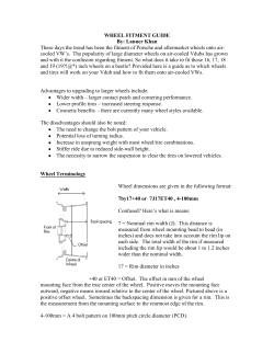
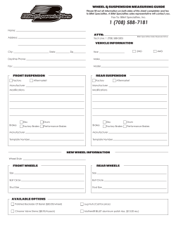
www.mavic.com
technical manual
02
THIS DOCUMENT ONLY CONCERNS THE NEW PRODUCTS IN 2002
ALL INFORMATION CONCERNING THE EXISTING PRODUCTS IN THE 1999, 2000 AND 2001 RANGES CAN BE FOUND RESPECTIVELY IN YOUR 1999, 2000 AND
2001 TECHNICAL MANUALS.. IF YOU DO NOT HAVE ONE OF THESE MANUALS, YOU CAN GET ONE THROUGH YOUR USUAL CONTACTS OR YOUR MSC.
THIS DOCUMENT ONLY UPDATES THE TECHNICAL INFORMATION AND SHOULD THEREFORE BE KEPT IN A SAFE PLACE FOR AN UNLIMITED LENGTH OF TIME
ALONG WITH THE MANUALS FROM PREVIOUS YEARS.
THE NEW 2002 TECHNICAL MANUAL
The 2001 Technical Manual, which is essential to ensuring the maintenance of Mavic products, consists of four main parts:
• wheels.
• rims.
• components/tools.
• Customer service.
You will find two types of technical information in each one of these parts:
• product schematics showing individual part numbers.
• the procedures to properly maintain our products.
Also the procedures to follow concerning the warranty and Mavic Customer Service Center.
As we have already mentioned, this document only offers technical information regarding the modifications of the 2001 products and new Mavic
products in the 2002 range:
• Wheels: Ksyrium® SSC SL, Ksyrium® Elite and Comete® ED 10.
• Rims: T520, T224, X3.1 Disc, F219 Disc.
We hope this document will meet your needs and we are always willing to listen to any suggestions to improve on it.
Thank you for your confidence in us and have a good 2002 season.
MAVIC CUSTOMER SERVICE
Our objective is for you to be the main service partner for the consumer.
You are also assured that through the use of our worldwide Mavic Service Center (MSC), you will benefit from maximum assistance, the best
possible service and professional advice.
Mavic MSC will be at your disposal to guide you through the necessary procedures in the event you need to return a part, make repairs, make
standard replacements, or to send you spare parts necessary for product maintenance.
We simply ask you to contact Mavic MSC prior to any returns (see page 27) to obtain the proper procedures for correct returns. Mavic will only
accept authorized returns.
For additional information contact your MSC or consult the last pages in this technical manual.
CUSTOMER
2
RETAILER
MSC
INTRODUCTION / Mavic Customer Service . . . . . . . . . . . . . . . . . . . . . . . . . . . . . . . . . . . . . . . . . . . . . . . . . . . . . .Pages
2/3
MAVIC WHEELS . . . . . . . . . . . . . . . . . . . . . . . . . . . . . . . . . . . . . . . . . . . . . . . . . . . . . . . . . . . . . . . . . . . . . . . . . .Pages
4 / 13
Segmentation of the range per level . . . . . . . . . . . . . . . . . . . . . . . . . . . . . . . . . . . . . . . . . . . . . . . . . .Page
4
General points . . . . . . . . . . . . . . . . . . . . . . . . . . . . . . . . . . . . . . . . . . . . . . . . . . . . . . . . . . . . . . . . .Page
4
Ksyrium® Elite wheel . . . . . . . . . . . . . . . . . . . . . . . . . . . . . . . . . . . . . . . . . . . . . . . . . . . . . . . . . . . . .Page
5
Ksyrium® SSC SL wheel . . . . . . . . . . . . . . . . . . . . . . . . . . . . . . . . . . . . . . . . . . . . . . . . . . . . . . . . . . .Page
6
Comete® wheel . . . . . . . . . . . . . . . . . . . . . . . . . . . . . . . . . . . . . . . . . . . . . . . . . . . . . . . . . . . . . . . .Page
7
Indexation compatibility . . . . . . . . . . . . . . . . . . . . . . . . . . . . . . . . . . . . . . . . . . . . . . . . . . . . . . . . . . .Page
8
Wheel maintenance . . . . . . . . . . . . . . . . . . . . . . . . . . . . . . . . . . . . . . . . . . . . . . . . . . . . . . . . . . . . .Pages
9 / 13
MAVIC RIMS . . . . . . . . . . . . . . . . . . . . . . . . . . . . . . . . . . . . . . . . . . . . . . . . . . . . . . . . . . . . . . . . . . . . . . . . . . . .Pages
14 / 21
Segmentation of the range per level . . . . . . . . . . . . . . . . . . . . . . . . . . . . . . . . . . . . . . . . . . . . . . . . . .Page
14
General points . . . . . . . . . . . . . . . . . . . . . . . . . . . . . . . . . . . . . . . . . . . . . . . . . . . . . . . . . . . . . . . . .Page
14
Descriptive chart of what’s new . . . . . . . . . . . . . . . . . . . . . . . . . . . . . . . . . . . . . . . . . . . . . . . . . . . . .Page
15
Wear & tear indicator . . . . . . . . . . . . . . . . . . . . . . . . . . . . . . . . . . . . . . . . . . . . . . . . . . . . . . . . . . . .Page
15
CONTENTS
CONTENTS
Conditions for using a rim . . . . . . . . . . . . . . . . . . . . . . . . . . . . . . . . . . . . . . . . . . . . . . . . . . . . . . . . .Pages 16 / 18
Special conditions of using a rim for disc brakes . . . . . . . . . . . . . . . . . . . . . . . . . . . . . . . . . . . . . . . . . .Page
19
Special conditions for using and building a UST® Tubeless rim . . . . . . . . . . . . . . . . . . . . . . . . . . . . . . . . .Pages 20 / 21
MAVIC COMPONENTS . . . . . . . . . . . . . . . . . . . . . . . . . . . . . . . . . . . . . . . . . . . . . . . . . . . . . . . . . . . . . . . . . . . . .Pages
SSC® brakes . . . . . . . . . . . . . . . . . . . . . . . . . . . . . . . . . . . . . . . . . . . . . . . . . . . . . . . . . . . . . . . . . .Page
22 / 24
22
Mavic tools . . . . . . . . . . . . . . . . . . . . . . . . . . . . . . . . . . . . . . . . . . . . . . . . . . . . . . . . . . . . . . . . . . .Pages 23 / 24
MAVIC CUSTOMER SERVICE . . . . . . . . . . . . . . . . . . . . . . . . . . . . . . . . . . . . . . . . . . . . . . . . . . . . . . . . . . . . . . . . .Pages
General procedure for any request for intervention . . . . . . . . . . . . . . . . . . . . . . . . . . . . . . . . . . . . . . . . .Page
25 / 27
25
Warranty and Mavic customer Service / To contact your MSC . . . . . . . . . . . . . . . . . . . . . . . . . . . . . . . . .Pages 26 / 27
3
WHEELS
SEGMENTATION OF THE WHEEL RANGE PER LEVEL
MTB
ROAD
LEVEL
CROSS-COUNTRY
AERODYNAMIC
MULTIPERFORMANCE
DOWNHILL
CLASSIC
UST® TUBELESS
COMETE®
KSYRIUM® SSC SL
COSMIC CARBONE
SSC
KSYRIUM ELITE
CROSSMAX
UST® DISC
New
3
CLASSICS® SSC
®
2
CLASSIC
DEEMAX® DISC
CROSSMAX
UST®
®
New
COSMIC® ELITE
CROSSROC
UST® DISC
CROSSRIDE®
CERAMIC
CROSSROC
UST®
CROSSRIDE®
COSMOS®
GENERAL POINTS
Dear dealers, we would like to remind you that it is your responsibility to give the customer all wheel instructions and have them fill out the warranty card.
Recommended wheel instructions for the customer:
• Choose a suitable wheel designed for the type of riding you wish to do.
• It is imperative to respect the instructions in this Technical Manual for tire pressure and dimensions (see following charts).
• Respect the appropriate spoke tensions. Mavic generally recommends spoke tensions between 90 and 110 kg. (for a front or rear wheel on the
free wheel side with 3 cross pattern). For more adapted information regarding every one of our products, please consult the following pages. An
inappropriate spoke tension can generate much stress and cause damage quickly to the rim.
• Clean the rims on a regular basis with the Mavic abrasive eraser (M40410).
• Remove gravel or metal particles in the brake pads.
• Replace the brake pads when they are worn.
• Do not use a rim if the braking surfaces are worn, if eyelets are missing or in any other case where safety might be compromised. Indeed, a rim is
a part that wears out as are brake pads, and need to be replaced if it is worn (sidewall hollowed by wear & tear or cut out, cracked rim);
• Check, or have your rims checked, on a regular basis. If this is not possible, check them at least in the beginning of each season and after intensive
use. When checking, look inside (especially under the rim tape) and outside the rim. Look for signs of fatigue, wear, damage to the braking
surfaces, or cracks in the walls around the eyelets.
You should also check if you have any doubt about proper spoke tensions or the correct type of tire to use.
Following these recommendations will guarantee longer product life for the wheels, maximum performance and riding enjoyment..
RECOMMENDED TIRE PRESSURE
CROSS-COUNTRY
DOWNHILL AND FREERIDE
Tire width
in ” in mm
25
1,00
30
1,20
1,50
38
1,75
45
1,85
47
1,90
48
1,95
50
2,00
51
2,10
53
2,20
56
2,50
63
Tire width
Maximum pressure Maximum pressure
(PSI)
(bars)
in ” in mm
113,00
7,70
1,00
25
103,00
7,00
1,20
30
88,00
6,00
1,50
38
76,00
5,20
1,75
45
71,00
4,80
1,85
47
69,00
4,70
1,90
48
66,00
4,50
1,95
50
63,00
4,30
2,00
51
59,00
4,00
2,10
53
2,20
56
55,00
3,70
2,50
63
40,00
2,70
Maximum
pressure (bars)
5,50
5,20
4,70
4,20
4,10
4,00
3,90
3,80
3,70
3,50
3,00
ROAD
Tire width
in mm
19
23
25
4
Maximum pressure
(bars)
10,0
9,5
9,0
Maximum pressure
(PSI)
146
138
131
Maximum
pressure (PSI)
81,00
76,00
69,00
62,00
60,00
59,00
57,00
56,00
55,00
52,00
44,00
WHEEL WEIGHT WITHOUT SKEWER:
FRONT: 755g
REAR M10: 960g REAR ED10: 940g
Use: to be used only on a road bike. Any other use (such as on a tandem, mountain bike,
cyclo-cross bike) is inadvisable, and is the sole responsibility of the user, which voids the Mavic
warranty.
CLINCHER WHEEL REF:
FRONT:
M24500
REAR M10: M24501
REAR ED10: M24502
RIM
COMMERCIAL REFERENCES
Ø VALVE HOLE
RECOMMENDED TIRE WIDTH AND PRESSURE
Front: M40663
Rear: M40664
Rim delivered with screwed eyelets
Ø: 6,5 mm
Length: ≥ 32 mm
Available through
the MSC
MAINTENANCE AND
BRAKES
Ø 700: ETRTO compatible
622 x 13
Width: see page 4
Maintenance:
see page 16 and 17
Width: see page 4
Replacing the rim:
see page 13
Brakes: see page 17
WHEELS
HUBS
M40318
M40243
M40242
M40052
M40063
M40578
M40563
M40242
M40589
M40660
M40660
M40578
M40067
M40591 (ED10)
M40592 (M10)
M40589
M40579
ED10
M40639 (11)
M40640
MAINTENANCE: Clean with a dry cloth or soap and water.
Do not use pressurized water. Maintenance: see pages 9 and 13 and 2000 Technical Manual pages 11, 13 and 15.
Caution: the parts on the free wheel (pawl assembly, springs, free wheel body) FTS-L version 2001 / 2002 are not compatible with those on the 2000
version of the FTS free wheel and before.
WHEEL BUILDING
FEATURES
TENSION
QUANTITY PER PACKAGE: 10 spokes + 10 ABS type of nipples
REFERENCE: Front: M40654 length 203 mm
Rear: M40656 length 303 mm
LACING PATTERN: Front: radial
Rear: 2 cross pattern
To make the spokes shiny, rub them with an oiled cloth.
MAINTENANCE
front: 110 - 130 kg
Lateral and radial truing:
Rear free wheel side: see 2001 Technical manual
page 20
140 - 160 kg
Replacing spokes:
see page 12
ACCESSORIES
WHEEL DELIVERED WITH:
• Front quick release skewer: M40350
• Rear quick release skewer: M40351
• Free play adjustment wrench: M40123 (with rear wheel only)
• Spoke maintenance wrench: M40567 (with rear wheel only)
• Instructions and warranty card.
5
WHEEL WEIGHT WITHOUT SKEWER:
Clincher: Front: 690g Rear M10: 840 Rear ED10: 820g
Tubular: Front: 680g Rear M10: 830 Rear ED10: 810g
Use: to be used only on a road bike. Any other use (such as on a tandem, mountain bike,
cyclo-cross bike) is inadvisable, and is the sole responsibility of the user, which voids the
Mavic warranty.
CLINCHER WHEEL REF: TUBULAR WHEEL REF:
Front: M24600
Front: M24610
Rear M10: M24601
Rear M10: M24611
Rear ED10: M24602
Rear ED10: M24612
RIM
COMMERCIAL REFERENCES
Ø VALVE HOLE
Front clincher: M40670
Rear clincher: M40671
Front tubular: M40668
Rear tubular: M40669
MAINTENANCE AND
BRAKES
RECOMMENDED TIRE WIDTH AND PRESSURE
Ø 700: ETRTO compatible
622 x 13
Width: see page 4
Ø: 6,5 mm
Length: ≥ 32 mm
Available through
the MSC
Maintenance:
see pages 16 & 17
Brakes: see page 17
Replacing the rim:
see 2000 Technical Manual
pages 19 & 20
See page 4
HUBS
M40456
M40458
M40461
M40076
M40467
M40676
M40579
M40075
M40667
M40461
M40076
M40067
M40578
M40578
M40075
M40591 (ED10)
M40592 (M10)
M40462
M40667
M40062
M40469 (M10)
M40662 (ED10)
M40639 (11T)
M40640 (12T / 13T)
MAINTENANCE: Clean with a dry cloth or soap and water.
Do not use pressurized water. Maintenance: see page 9 and 2001 Technical Manual pages 17, 18 & 19.
Caution: the parts on the free wheel (pawl assembly, springs, free wheel body) FTS-L (2001 / 2002 version) are not compatible with those on the FTS
free wheel (2000 version and before).
WHEEL BUILDING
FEATURES
TENSION
QUANTITY PER PACKAGE: 10 Zicral spokes with anti-rotation system and brake ring (see below).
REFERENCE: Front:
M40677
Right rear:
M40678
Left rear:
M40679
LACING PATTERN: Front:
radial
Right rear: radial, Isopulse system
Left rear: 3 cross pattern, Isopulse system
Front: 100 à 120 kg
Rear free wheel side:
130 - 150 Kg
MAINTENANCE
Lateral and radial truing
see 2001 Technical Manual
page 20
Replacing the spokes:
see 2000 Technical Manual
pages 17 and 18
The spokes on the Ksyrium® SSC SL wheel are different than the spokes on the 2000 and 2001 Ksyrium® SSC, not by their length, but due to the fact
that they are “self-locking” with a brake ring system compressed between the nipple and the spoke itself, at the level of the head, when the spoke
tension is adjusted. Therefore, it is not necessary to glue them. These spokes can be mounted on the Ksyrium® SSC 2000 and 2001.
ACCESSORIES
WHEEL DELIVERED WITH:
• Front quick release skewer BR 601: M40149
• Rear quick release skewer BR 601: M40150
• Free play adjustment wrench: M40123 (only with the rear wheel)
6
• Spoke maintenance and tension wrenches (delivered with the rear wheel):
M40494 (only with the rear wheel)
• Instructions and warranty card.
In 2002, only the road version has been improved on. The information below concerns this
version only.
Use: Rear wheel designed for road events ((racing in a line, time trials, triathlon). To be used
only on a road bike. Any other use (such as on a tandem, mountain bike, cyclo-cross bike)
is inadvisable, and is the sole responsibility of the user, which voids the Mavic warranty.
WHEEL WEIGHT WITHOUT SKEWER:
Clincher: Rear M9: 1300g
Rear ED10: 1260g
Tubular: Rear M9: 1300g
Rear ED10: 1260g
Clincher wheel ref:
Rear M9: M20106
Rear ED10: M20110
Tubular wheel ref:
Rear M9: M20107
Rear ED10: M20120
RIM
Ø VALVE HOLE
MAINTENANCE AND BRAKES
RECOMMENDED TIRE WIDTH AND PRESSURE
Ø 700: ETRTO compatible
622 x 13 (clincher), 633 mm tubular
Width: 18 - 23 mm
Ø: 6,5 mm
Length: ≥ 32 mm
Maintenance: see pages 16 & 17
Brakes: see page 17
Mini: 7 bars / 100 PSI
Maxi: 10 bars / 145 PSI.
WHEELS
HUBS
M9
M40705
M40127
M40066
M40068
M40067
M40066
M40147
M40077
ED 10
M40077
M40127
M40579
M40578
M40067
M40591
M40639 (11)
M40640 (12)
M40578
M40704
MAINTENANCE: Clean with a dry cloth or soap and water.
Do not use pressurized water. Maintenance: see pages 10 / 11 and 1999 Technical Manual pages 41, 46 and 47.
Caution: the nose of the hub body and the parts of the FTS-L free wheel (pawl assembly, springs, free wheel body) 2001 / 2002 version are not
compatible with nose of the hub body and parts of the FTS free wheel 2000 version and before.
In addition to the difference with the other level 3 wheels, the M9 and ED10 free wheel bodies are not interchangeable on this wheel.
The M9 version has an FTS system from the 1st generation, whereas the ED10 version has adopted the new FTS-L system.
THE M9 VERSION ACCOMMODATES THE M10 CASSETTES.
WALLS AND RIM
MAINTENANCE
FEATURES
Asymmetrical carbon walls: carbon segments / honeycomb / carbon
segments. High resistance aluminum alloy SUP welded rim and
UB Control sidewalls.
Adjusting the bearings:
• Lock the wheel in the frame and put the bike on the ground;
• If there is free play, slightly tighten the brake nut using a 14 mm flat
wrench and check the free play at the top of the wheel.
• If too tight: loosen the Bearing Adjustment Cap about a half turn; unlock
the wheel; remove it from the frame and remove the skewer; with a
mallet, lightly hit the brake nut side to obtain a freer rotation; mount the
wheel on the frame and readjust as in the first case.
ACCESSORIES
WHEEL DELIVERED WITH:
• Skewer BR 601 Composite M40150
• Rim tape 16 x 622 (clincher version only)
• Bag M40135
• Instructions and warranty card
7
INDEXATION COMPATIBILITY OF ROAD WHEELS
To offer total indexation compatibility with the different cassettes and derailleurs on the market, Mavic has developed a new FTS-L free wheel design
that allows level 3 wheels to accommodate:
- the 8 or 9 speed HG cassettes, on the M10 wheels, for a Shimano 8 or 9 speed compatibility, or Mektronic (9 V);
or
- the Mavic M10 cassettes, on the M10 wheels, for a Campagnolo 8, 9 or 10 speed compatibility, or Mektronic (9 V);
or
- the ED 9 or 10 speed cassettes, on the ED10 wheels, for a Campagnolo 9 or 10 speed compatibility.
As for level 2 wheels, they are available in the M9 / M10 version and accommodate the Mavic M10 or Shimano 8 or 9 speed cassettes.
To synthesize this information and know the different possibilities available to you depending on your wheel version, we offer the following recap chart:
Indexation
Mavic Mektronic
Number of speeds
Version of Mavic wheel
Type of cassette
9
8
M9 or M10
M10
HG9
Positioning spacer*
9
8
HG8
HG9
9
M40409
Origin
Gray
10
M9 or M10
M10
M10
M10
With
Origin
Color
Campagnolo
M9 or M10
With
Ref
Spacer
Shimano
HG9
ED10
M10
ED10
ED9
M10
ED10
Without
M40409
M40182
M40181
M40253
Gray
Alu
Yellow
Gray
Origin
M40573
Origin
Origin
Black
*: The positioning spacer is supplied with the M9 / M10 wheels and the gray spacer kit M40409. It must be saved for mounting with a Mavic
Mektronic or Shimano transmission, and removed for mounting with a Campagnolo transmission.
The Mavic M10 cassette is originally designed for Campagnolo 9 speed compatibility (yellow spacers M40181) or 10 speed (black spacers M40573).
These 2 sets of spacers are delivered with the M10 Kit.
However, for this cassette to be compatible with a Mavic Mektronic transmission or Shimano 9 speed, you have to order the gray spacer kit M40409
separately.
Also, for compatibility with a Campagnolo 8 speed, you have to order the alu spacers M40182 separately.
It is also possible to mount a Shimano cassette for compatibility with a Campagnolo derailleur. You just need to use a Mavic M9 / M10 wheel,
a Shimano cassette such as the Ultegra or Dura Ace and the Mavic HG-CC9 spacer (M40253).
WHICH WHEEL FOR WHICH COMPATIBILITY:
Generally speaking, the wheels with the FTS -L system, that is level 3 wheels, are offered in the M10 and ED10 version. The other wheels exist only
in the M9 / M10 version.
The following is a recap of the wheels in the 2002 range:
One M9 / M10 version: Cosmos®, Cosmic® Elite
The choice of ED10 or M10: Classics® SSC, Ksyrium® Elite, Ksyrium® SSC SL, Cosmic® Carbone SSC, Comete® road (M9).
NOTE: For the Ksyrium® SSC SL wheel, you absolutely must keep the Chain Disc initially mounted on the free wheel body (remove the rubber shipping
band that holds the Chain Disc), which will protect the aluminum spokes in case the chain passes between the last cog and the spokes. Then
depending on the option chosen, you will install a spacer if needed and then the corresponding cassette.
8
WHEEL MAINTENANCE
Reminder of the Mavic warranty
Prior to any repair of a Mavic wheel (or on any other Mavic product), please note that it has a warranty against manufacturing or material defects for
a period of one year from the date of original purchase (see Mavic Warranty page 26).
This means that:
- during the warranty period, and when it definitely applies to the warranty (first contact your MSC), you must return the Mavic wheel (or any other
Mavic product) directly to your MSC following the procedure explained on page 25 to get the Mavic warranty.
However, if you decide to repair the wheel by yourself (or any other Mavic product), your customer will lose the Mavic warranty.
• after the warranty period and in case of repair, we advise you to refer to the following pages to intervene on the Mavic wheel. If replacing the rim,
please note the new serial number of the rim on the original warranty card and the date of intervention.
WHEELS
Only this procedure will allow your customer to get the Mavic warranty on the replaced rim.
Repairs
The following pages will help you to:
- Replace an axle kit and a bearings kit on the front hub of the Ksyrium® Elite;
- Replace an axle kit on the rear hub of the Ksyrium® Elite;
- Replace a free wheel body kit on the rear hub of the Ksyrium® Elite;
- Replace a bearings kit on the rear hub of the Ksyrium® Elite;
- Replace a spoke on the Ksyrium® Elite;
- Replace a rim on the Ksyrium® Elite.
Before any operation, we recommend removing:
- the wheel from the bike by releasing the quick release skewer.
- the skewer, the tube or the tire and the rim tape.
- the cassette and chain disc (if necessary) for the rear wheel.
FRONT BEARING AND AXLE KIT FOR THE KSYRIUM® ELITE WHEEL
Tools needed
• 1 x 5 mm Allen wrench
• 1 hub wrench M40123
• Bearing pullers M40373
1
Remove the fork support on the adjustment nut side. This is press fit on the end of the axle;
2
Insert a 5 mm Allen wrench on the opposite side of the adjustment nut and loosen the adjustment nut;
3
Remove the axle;
4
Drive out the bearings with the bearing pullers M40373;
5
Mount the new bearings using the bearing pullers M40373;
6
Mount the axle: insert the 5 mm Allen wrench in the axle and tighten the adjustment nut;
7
Clip the fork support back on;
8
Put the wheel back in place on the fork, tighten the quick release skewer and adjust the bearing free play using the hub wrench M40123.
2
3
4
5
9
REAR AXLE KIT FOR THE KSYRIUM® ELITE WHEEL
Tools needed
• 2 x 5 mm Allen wrenches • 1 hub wrench M40123
1
Loosen the free play adjustment nut one turn using the hub wrench M40123,
to avoid damaging the bearings when mounting the axle again;
2
Insert a 5 mm Allen wrench in each end of the axle;
3
Loosen the axle end screw using the 2x 5 mm Allen wrenches;
4
Remove the axle by pushing on the axle end screw to extract it on the opposite side of the free wheel;
5
Replace the axle and mount it again using the 2 x 5 mm Allen wrenches;
6
Mount the wheel on the frame (or the fork) and adjust the bearing free play using the hub wrench M40123.
2
4
FREE WHEEL BODY KIT FOR THE KSYRIUM® ELITE WHEEL
Tools needed
• 2 x 5 mm Allen wrenches / • Mavic mineral oil M40122
1
Disassemble the complete axle kit (see above);
2
Remove the FTS-L free wheel body kit:
2.1 Pull the FTS-L free body wheel towards the exterior until it doesn’t move any further (about 4 mm);
2.2 Turn the FTS-L free wheel body, and while holding the pawls and springs, pull it carefully off the hub axle;
Caution: When you disassemble the FTS-L free wheel body, its pawls and springs are no longer supported and can therefore pop out. This can be prevented by
holding the pawls with your hand.
3
Remove the spring /pawl assembly and clean it;
4
Replace the FTS-L free wheel body kit and the lip seal (install the new one against the nose of the hub, the lip toward the outside).Lubricate the lip
with Mavic mineral oil M40122;
5
Lubricate the inside of the FTS-L free wheel body kit in the cog area (10 - 20 drops of Mavic mineral oil M40122).
6
Install the spring/pawl assembly (spring fits over the pins of the centering stud on the pawl assembly). Put the springs and then pawl assembly in
place, the round side touching the axle. Then pivot the pawl assembly.
Install the FTS-L free wheel body kit:
7
7.1 Make sure the spacer washer M40067 (available in a kit with 10 parts) is placed inside the FTS-L free wheel body kit: The absence of this
spacer washer prevents the free wheel body from working properly.
7.2 Install the FTS-L free wheel body kit holding the pawl assembly in your hand in the low position (springs compressed);
8
Install the axle end screw and the axle kit and adjust the bearings as described in the above procedure.
It is recommended to lubricate the free wheel body 1 or 2 times a year or whenever it gets noisy. To do this, follow the above procedure.
2.2
10
4
5
6
7.2
REAR BEARING KIT FOR THE KSYRIUM® ELITE WHEEL
Tools needed
• 2 x 5 mm Allen wrenches
• 1 hub wrench M40123
• Bearing pullers M40119 and M40373
1
Disassemble the complete axle kit and free wheel body kit by following the above procedures.
2
Remove the bearings on the free wheel side using the bearing press M40119 (long shank) and the bearings opposite the free wheel side using the
bearing press M40373;
After cleaning the body, install the new bearings:
3
3.1 On the free wheel side using the bearing press M40119;
3.2 Opposite the free wheel side using the bearing press M40373;
Install the axle kit and free wheel body by following the procedure described above.
WHEELS
4
2
2
3.1
3.2
11
REPLACING THE SPOKES ON THE KSYRIUM® ELITE WHEEL
CAUTION:
When a spoke is bent or broken, the spokes that are intact are under excess tension. To avoid breaking more spokes and eliminate this excess tension,
you must loosen all the spokes. After replacing the bad spokes, increase the tension to its original level.
Tools needed
• 1 spoke wrench
• 1 hollow screw wrench M40630
• 1 tensometer + tension reading conversion chart, adapted to the tensometer used
• 1 wire cutter
• Oil
• Loctite® 243 thread lock or equivalent
• A hollow screw per spoke to be replaced
• A wrench for flat spoke maintenance M40567
1
Loosen the spoke nipple using the spoke wrench to eliminate the tension;
2
Loosen the hollow screw on the damaged spoke using the wrench M40630 (caution, left hand thread);
3
Cut the spoke, if necessary, or remove it;
4
Insert the new spoke into the hub;
5
Install the hollow screw head first on the spoke, then tighten the spoke nipple about 3 turns;
6
Put the new spoke properly in place. Then after having glued the hollow screw with thread lock, tighten the hollow screw in the rim using the wrench
M40630 (caution: left hand thread, torque: 5.5 Nm);
7
Put a drop of oil around the spoke nipple so it doesn’t jam on the hollow screw.
8
Tighten the spoke nipple to restore the spoke tension:
110 - 130 Kg on the front wheel and 140 - 160 Kg on the rear free wheel side;
9
Check the lateral and radial truing of the wheel.
5
12
6
6
7
8
REPLACING THE RIM ON THE REAR KSYRIUM® ELITE WHEEL
Tools needed
• 1 spoke wrench • 1 hollow screw wrench M40630 • 1 tensometer + tension reading conversion chart adapted to the tensometer used
• 1 wire cutters • Oil • Loctite® 243 thread lock or equivalent • A package of hollow screws M40595
• A flat spoke maintenance wrench M40567
1
Start on the free wheel side;
2
With the rim flat, locate the valve hole and turn the rim so the raised indicator bumps are to the right of the valve hole;
Prepare the first half of the free wheel side:
3
3.1 Insert a hollow screw head first in the spoke. Then tighten the spoke nipple about 3 turns.
3.2 Put the spoke in the slot inside the hub on the free wheel side and tighten the hollow screw one turn in the 1st hole in the rim to the right of the
valve hole;
WHEELS
3.3 Repeat the 2 procedures above for the first half of one side:
1 hole out of 4 in the rim and always in the inside slot on the free wheel side;
4
Then prepare the second half of the free wheel side;
4.1 Insert a hollow screw head first on a spoke. Then tighten the spoke nipple about 3 turns;
4.2 Put the spoke in the outside slot of the hub on the free wheel side and tighten the hollow screw one turn in the 3rd hole on the rim to the right of
the valve hole;
4.3 Repeat the 2 procedures above for all of the second half of the side:
1 hole out of 4 on the rim and always in the outside slot on the free wheel side;
5
Turn the wheel over to have the opposite of the free wheel side facing you;
6
Prepare the 3rd half side, opposite the free wheel side:
6.1 Insert a hollow screw head first on a spoke. Then tighten the spoke nipple about 3 turns;
6.2 Put the spoke in the outside slot of the hub on the opposite free wheel side and tighten the hollow screw one turn in the 1st hole on the rim to
the right of the valve hole;
6.3 Repeat the 2 procedures above for all of the third half of the side:
1 hole out of 4 on the rim and always in the outside slot opposite the free wheel side;
Prepare the 4th half of the side:
7
7.1 Insert a hollow screw head first on a spoke. Then tighten the spoke nipple about 3 turns;
7.2 Put the spoke in the outside slot of the hub on the opposite free wheel side and tighten the hollow screw one turn in the 3rd hole on the rim to
the right of the valve hole;
7.3 Repeat the 2 procedures above for all of the fourth half side:
1 hole out of 4 on the rim and always on the outside slot opposite the free wheel side;
8
Once all the spokes are prepared, put thread lock on the threads of every hollow screw and completely tighten every hollow screw with the hollow
screw wrench M40630. Caution, left hand thread, torque: 5.5 Nm;
9
Put a drop of oil around each spoke nipple so they don’t jam against the hollow screws;
10
Adjust the final tension of the wheel: 140 - 160 Kg for the rear wheel on the free wheel side.
11
Check the lateral and radial truing of the wheel.
3.1
3.2
4.2
6.2
8
8
9
10
7.2
13
RIMS
SEGMENTATION OF THE RIM RANGE PER LEVEL
Rims
Level
Road
Clincher
Classic
Profiled
3
Open Pro
CXP 33
2
MA3
CXP 23*
CXP 21*
1
MTB
Tubular
Cross-Country
Cross-Country UST®
Touring
Freeride
Classic
Classic
brake
Disc
brake
Disc
brake
Classic
brake
Reflex
X618
X517
X317
DISC
X3.1 UST®
DISC
New
F519
X225*
X221*
X223
DISC*
Disc
brake
Downhill
Classic
brake
Disc
brake
Classic
brake
D521
D321
T520
New
F219 DISC
New
X139*
* Specific O.E.M. rims
GENERAL POINTS
All Mavic rims are based on these four principles:
• aluminum alloy profile (6000 series) specified by Mavic.
• double wall profile for greater strength and rigidity.
• anodization for its corrosion-resistance and aesthetic qualities while facilitating maintenance.
• the eyelet allows for better distribution of the pressure exerted by the spoke and increases the strength and durability of the Mavic rim.
The profiled eyelet (Mavic patent) combines the benefits of both the profiled rim and eyelet.
14
T224
New
WHAT’S NEW FOR 2002
4 new rims are introduced in the 2002 range. Their features are the following:
TOURING RIMS
Rim width
MTB RIMS
T520
T224
F219 DISC
24,5
18,5
24
18,2
28
21
18
19,8
X3.1 UST® DISC
22,3
19
21,2
20
Technologies
Material
6106
6106
6106
Maxtal
6,5
6,5
6,5 or 8,5
6,5
Recommended tire width
28 - 37
28 - 37
1,5 - 2,3
1,5 - 2,2
Eyelets
Double
Simple
Simple
Fore hollow screws
565
530
570
450
Ceramic
36
-
-
-
Mavic black
36
-
32,36
32
36, 40, 48
36
-
12
12
12
16
598 mm
602 mm
536 mm
532 mm
622 x 20 x 0,6
622 x 20 x 0,6
23 x 559 x 0,6
Do not use
rim tape
Yes
Yes
-
-
Valve hole diameter (in mm)
Average weight (in grams)
Finish
and drilling
Silver
Recommended spoke nipple length
Spoke support diameter
Recommended rim tape
(ETRTO x width x thickness)
RIMS
Wear indicator
®
THE WEAR & TEAR INDICATOR
For safety reasons, and also to conform to the legislation of certain countries, Mavic has chosen to provide its Touring rim range with a wear & tear
indicator.
The principle: a little hole appears on each of the 2 braking surfaces on the rim, when there is too much wear & tear on the rim.
This indicator is materialized by 2 yellow arrows on the stickers on the rim, opposite the valve hole.
Depending on the adjustment of the brake pads, it is possible for the wear & tear indicator to appear on only one of the 2 braking surfaces.
In any case, once the wear & tear indicator appears on at least one of the 2 braking surfaces, it could be dangerous to continue to use this rim,
and it should be replaced as soon as possible.
15
CONDITIONS OF USE FOR A RIM
CONDITIONS OF USE TO BE GIVEN TO YOUR CUSTOMERS:
Mavic uses the most advanced technology in the design of its rims and wheels. However, a rim cannot last forever and wears down according to its
use: type of riding, terrain, brake pad, spoke tension, tires, tire pressure, weather conditions.
Each rim has been designed for a specific use and discipline (road, cross-country, downhill, touring). Any other use of a rim for which it has not been
designed is inadvisable and is the sole responsibility of the user, which voids the Mavic warranty.
Please advise customers of the following:
• Choose a suitable rim designed for the type of riding you wish to do.
• Respect the instructions for tire pressure and dimensions mentioned in this Technical Manual (see following diagrams).
• Respect appropriate tension of spokes. Mavic recommends tension of spokes between 90 and 110 divisions with a Hozan type of tensionmeter
(70 - 90 kg) (for a front or rear wheel on the free wheel side with 3 cross pattern).Inappropriate tension of spokes can generate too much stress
and damage the rim.
• Do not use cross-country rims on wheels that will be mounted on freeride, downhill or dual bikes.
• Rims must be cleaned on a regular basis with Mavic abrasive eraser (M40410).
• Remove gravel or metal particles in the brake pads;
• Replace the brake pads when they are worn.
• Discontinue use of a rim if the braking surfaces are worn, if eyelets are missing, or in any other case where safety might be compromised.
The rim is a component that gets worn out in the same way as the brake pads, and must be replaced if it is worn (sidewalls hollowed by wear or
indented, cracked rim...),
• For the T520 and T224, do not continue to use the rim if the wear & tear indicator appears on at least one of the 2 braking surfaces.
• Check or have your rims checked on a regular basis. If this is not possible, check them at least in the beginning of each season and after intensive
use. When checking, look inside (especially under the rim tape) and the outside rim. Look for signs of fatigue or wear, damage to the braking
surfaces, appearance of the wear & tear indicator (only for the T520 and T224), or cracks in the walls around the eyelets.
Following these recommendations will guarantee longer product life for the rims, maximum performance and riding enjoyment.
RECOMMENDED TIRE PRESSURE:
CROSS-COUNTRY
in ”
1,00
1,20
1,50
1,75
1,85
1,90
1,95
2,00
2,10
2,20
2,50
Tire width
in mm
25
30
38
45
47
48
50
51
53
56
63
DOWNHILL AND FREERIDE
Maximum
Maximum
pressure (bars) pressure (PSI)
7,70
113,00
7,00
103,00
6,00
88,00
5,20
76,00
4,80
71,00
4,70
69,00
4,50
66,00
4,30
63,00
4,00
59,00
3,70
55,00
2,70
40,00
in ”
1,00
1,20
1,50
1,75
1,85
1,90
1,95
2,00
2,10
2,20
2,50
Tire width
in mm
25
30
38
45
47
48
50
51
53
56
63
ROAD
Tire width
in mm
19
23
25
28
16
Maximum
pressure (bars)
10,0
9,5
9,0
8,0
Maximum
Maximum
pressure (bars) pressure (PSI)
5,50
81,00
5,20
76,00
4,70
69,00
4,20
62,00
4,10
60,00
4,00
59,00
3,90
57,00
3,80
56,00
3,70
55,00
3,50
52,00
3,00
44,00
TOURING
Maximum
pressure (PSI)
146
138
131
117
Tire width
in mm
28
30
32
35
37
Maximum
pressure (bars)
7,00
7,00
7,00
6,00
6,00
Maximum
pressure (PSI)
103,00
103,00
103,00
88,00
88,00
DURABILITY:
A rim has two main functions: to support the tire and serve as a brake disc.
In the framework of this second function as a braking surface, rims may be subject to wear, especially from intensive or prolonged use. Rims may
experience wear for reasons as diverse as the encrustation of gravel or mud in the brake pads or the use of worn or poorly adjusted brake pads.
These can wear down or damage the rim sidewalls, and may not be noticed by the user.
It is common for the user to have the rims replaced as he would the brake pads.
You must make your customers aware of this.
To reduce wear and tear, we have developed CERAMIC coating on our top-of-the-line rims.
If, following a violent shock the rim is heavily out of true, the rim should be replaced as soon as possible, in order to avoid overloading or even rupture.
MAINTENANCE:
Rims and brake pads must be cleaned with soap and water on a regular basis. Abrasive substances (sand...) may have been deposited during use
and could scratch or significantly damage the sidewalls of rims.
If the cleaning is not sufficient on the braking surfaces, use a Mavic abrasive eraser (M40410) except on rims designed specifically for disc brakes.
Only use the Mavic abrasive eraser, a sponge, or a cloth.
If grease exists on a rim, it may be removed with any type of solvent without risking damage to the rim (except on the rim of the Deemax® wheel).
However, do not use any solvents in the area of the sticker or tire, as there is risk of damage to the sticker and tire.
BRAKE PADS:
Adjusting the brake pads:
The brake pads should be positioned on the braking surface of the rim, as shown in the diagram below:
MTB rim:
RIMS
Road rim:
OK
NO
1 mm
minimum
OK
NON
Recommendations for use and type of brake pad:
For proper braking:
• Clean the brake pads with the Mavic abrasive eraser M40410.
• Avoid all types of greasy substances on the braking surface.
• Use brake pads that are adapted to the specific rim coating. Certain brake manufacturers offer specific Ceramic pads. These pads should be used
only with Ceramic rims to avoid prematurely damaging the braking surface. Nevertheless, Mavic will never be able to guarantee the perfect
appropriateness between the brake pads of the different manufacturers with its different coatings on the braking surface (UB Control, Ceramic);
• Check the degree of wear and tear and the smoothness of the brake pads. Replace them on a regular basis.
To avoid braking noise, optimize the adjustment of the braking system by following the recommendations above, but also by trying to adjust the
different pad angles, and by mounting (if necessary) a stiffener.
17
CHARACTERISTICS OF THE CERAMIC COATING:
The main advantage of this coating is that it reduces the braking distance in wet conditions and increases the durability of the rim.
Initially, the wear and tear of the brake pads will be greater with this type of coating than with a conventional treatment.
Consequently, use brake pads specifically manufactured for rims with Ceramic coating.
Also, since this Ceramic coating is very hard, it is also sensitive to impacts.
A hard impact could cause cracks in the Ceramic coating, which would have no effect on the efficiency of the braking.
TUBULAR TIRE MOUNTING
Tools needed:
• solvent
• compressed air
• high grade tubular tire glue
• small paint brush
• steel wool
Process:
Any previously used rim and/or tire must be thoroughly cleaned and free of old glue before mounting.
The rim should be cleaned with acetone or a similar product before application of glue.
1 Prepare the clean tire mounting surface of the rim by rubbing it with steel wool.
2 Thoroughly coat the prepared mounting surface with glue, using a small paintbrush.
3 After the glue has dried, repeat process twice and allow the final coat of glue to dry
(the rim should have at least three dry coats of glue).
4 Inflate the tire and coat the tire base tape (inside diameter of tire) with glue.
5 Deflate (not completely) the tire while the glue is still wet and insert the valve stem through the valve stem hole of the rim. Carefully stretch
the tire onto the rim, working evenly from both sides of the valve stem, to the point opposite the valve stem.
6 Adjust the position of the tire until it is centered on the rim.
7 Inflate the tire to 45-60 PSI (3-4 bars). Allow the glue to dry for 12 hours before riding on the tire.
Then inflate to the pressure indicated on the tube.
18
SPECIAL CONDITIONS OF USE FOR A RIM WITH DISC BRAKES
This type of rim is specifically designed to be used with disc brakes and is characterized by:
- the absence of a braking surface.
- the specific shape and thickness of the profile.
For these reasons, these rims must be used only with disc brakes and never with cantilever or V-brakes.
These conditions also apply to the X223 DISC, X317 DISC, D321 DISC, F219 DISC, X3.1 UST® DISC, but also on the Crossmax UST® Disc,
Crossroc UST® Disc and Deemax® wheels or when the following sticker is positioned on your rim.
Wheel building recommendations:
Wheel building for this type of rim must be adapted to the strong forces that result from disc braking.
Mavic recommends to specifically orient the braking spokes (spokes on the outside of the hub flange) on the side of the disc so that they work in the
direction of the torque exerted by the disc on the hub.
Therefore, please follow the direction of the spokes on the hub flanges as is shown in these diagrams.
Direction of
wheel rotation
Braking spokes
FRONT WHEEL
RIMS
Braking torque
REAR WHEEL
SPECIAL CONDITIONS OF USE AND BUILDING A UST® TUBELESS RIM
The ETRTO norm now integrates the tubeless concept. As a result, and on the condition of respecting certain conditions of use, a UST® rim can officially,
and without risk, be combined with a classic tire and a tube.
USE OF A UST® TUBELESS RIM WITH A UST® TUBELESS TIRE
Especially after building a UST® Tubeless rim and mounting a UST® Tubeless tire, we recommend making sure the wheel/tire unit is airtight by
proceeding as follows:
1
Immerse the tire/wheel unit in the container of water.
2
Make sure the unit is airtight, by inspecting the tire and the rim (especially around the spokes) looking for air bubbles.
3
If there is a leak:
• Between the tire and the rim: replace or repair the UST® Tubeless tire.
• Around the UST® valve: replace the UST® valve.
• Around the hollow screws, spoke nipples or Zicral spoke screws: replace the rim.
Caution: the air contained between the 2 bridges of the rim will naturally have a tendency to escape because of the pressure of the water
and could be the origin of the air bubble. Therefore, check this phenomena before planning on replacing the rim.
19
USE OF A UST® TUBELESS RIM WITH A CLASSIC TIRE AND A TUBE
The 2 main conditions for using a UST® Tubeless rim with a classic tire and a tube are:
• only use ETRTO compatible tires.
• only use tubes with a Presta type of valve (ø 6,5);
• use a UST® Tubeless rim WITHOUT rim tape;
Once the UST® Tubeless valve has been removed, you can only insert a Presta type of tube (small valve, ø 6.5 mm) into the valve hole of the
UST® Tubeless rim.
Caution: never try to make the valve hole bigger or to drill it. If you do, you could permanently damage the rim and would not be able to use the UST®
valve, which is necessary to keep the rim airtight.
When mounting a classic tire on a UST® Tubeless rim, follow the same procedure as when using a UST® Tubeless tire. That is:
1
Abundantly moisten the rim tape and tire beads with soap and water;
2
Insert the first tire groove into the bottom of the rim groove;
3
Place the Presta tube in the classic manner;
4
Then install the second bead by starting on the opposite side of the valve and finishing at the valve;
5
Center the heels of the tire on both sides of the valve;
6
Rotate the tire to make sure the beads are properly placed at the bottom of the rim groove;
7
Inflate the tire energetically until the tire beads lock into place. The locking action can generate a series of short sounds due to the tire rising
to its final position. Inflate up to 5 bars to be sure that the tire is firmly in place. Being locked in place does not make the tire/rim system
completely airtight, but it does guarantee that the tire is properly held in place. In this way, the tire will be properly placed in the rim groove
and you can ride without risk of it rolling off the rim.
8
Adjust the tire pressure to your type of riding and preference. Caution: When using a UST® rim with a classic tire and tube, the adjustment of
the pressure is not “without risk”, just like on “all UST®” assembly (tire + rim).
20
BUILDING THE X3.1 UST® DISC RIMS
Tools needed
• A classic spoke wrench
• A hollow screw wrench M40630
• Loctite® 243 thread lock or equivalent
Build a tubeless rim in the classic manner except for the points below:
1
Insert a hollow screw head first into the spoke. Then tighten the spoke nipple about 3 turns.
2
At first, tighten the hollow screw in the corresponding rim hole only one turn.
3
Once all the spokes are properly placed, put the Loctite® 243 thread lock or equivalent on the hollow screws.
4
Tighten the hollow screws with the wrench M40630. Caution: Left hand thread. Torque: 5.5 Nm.
5
Put a drop of oil around every spoke nipple so they don’t jam against the hollow screws.
6
Adjust the spoke tension with a classic spoke wrench by using the spoke nipples. Never use the hollow screws.
Recommendations for building a disc rim: see page 19.
Mavic recommends using a minimum length of 16 mm spoke nipples only for 2 reasons:
-To avoid losing a nipple between the 2 walls of the rim when removing or building the rim.
-To avoid damaging the hollow screws with the spoke wrench, if the nipple does not sufficiently cover the screw.
Do not use the hollow screws to adjust the radial truing of the wheel.
RIMS
The hollow screws must be glued, and then completely tightened, using a 5.5 Nm torque. The spoke nipples must be used to build and adjust the wheel.
Once the tension of the wheel has been adjusted, the hollow screws must never be tightened or loosened. To remove one, first remove the spoke.
1
2
3
4
5
21
COMPONENTS
SSC® BRAKES
WEIGHT: 314 GRAMS the pair of calipers
REFERENCE: M70037
M40499
M40603
M40501
M40500
M40498 (X2)
M40497 (X2)
MAINTENANCE
Tools needed: • 1 x 5 mm Allen wrench • 1 x 4 mm Allen wrench • 1 x 2.5 mm Allen wrench • Grease
REPLACING THE SPRING:
1
Unclip the spring by depressing the straight part of the spring.
2
Replace the spring.
3
Insert the new spring in the caliper by first inserting the spring hook and finishing with the rectilinear part
(to be inserted behind the caliper pin).
4
Make sure the spring is well-placed by manipulating the caliper at least 10 times.
REPLACING THE CABLE CLAMP KIT:
Loosen the cable clamp screw using the 4 mm Allen wrench.
1
Replace the cable clamp and the screw.
2
Put grease on the cable clamp screw thread.
3
Caution: do not put grease on the cable clamp groove.
Install the cable clamp and cable clamp screw unit by passing the brake cable in the groove.
4
5
Adjust the tension of the cable and tighten the cable clamp screw using the 4 mm Allen wrench. Torque: 7 - 9 Nm.
REPLACING THE BRAKE PAD SET / BRAKE SHOES:
1
Loosen the brake shoe screw using the 4 mm Allen wrench.
2
Loosen the brake pad screw using the 2.5 mm Allen wrench.
3
Replace the brake pad.
Caution: make sure the brake pad corresponds to the brake shoe (left brake pad L/ right brake pad R).
4
Install the brake pad in the brake shoe and tighten the brake pad screw using the 2.5 mm Allen wrench.
5
Torque: 8.5 Nm.
6
Install the brake shoe on the caliper with the support washer under the head of the screw and the joint on the brake shoe.
7
Place the brake shoe in the proper position in relationship to the braking surface on the rim and tighten the screw using the 4 mm Allen wrench.
Torque: 4 - 6 Nm.
It is possible to remove the brake pad without removing the brake.
REPLACING THE ADJUSTABLE CABLE STOP:
1
Loosen the cable clamp screw using the 4 mm Allen wrench and remove the brake cable.
2
Loosen the adjustable cable stop.
3
Replace the adjustable cable stop and the brake cable stop.
4
Grease the thread on the adjustable cable stop.
5
Install the brake of the adjustable cable stop in the caliper groove.
6
Tighten the adjustable cable stop so it is in contact with the adjustable cable stop brake.
7
Install the brake cable and tighten the cable clamp screw using the 4 mm Allen wrench.
Torque: 7 - 9 Nm.
22
THE MAVIC TOOLS
REFERENCE NAME
M40119
Bearing press kit for the wheels:
Crossmax UST®
Crossmax UST® Disc
Deemax® (rear wheel only)
Ksyrium® SSC SL
Ksyrium® Elite (rear free wheel side only)
PRODUCT
A
D
C
B
M40120
Bearing press kit for the wheels:
Cosmic® Carbone SSC,
Classics® SSC,
Comete®
A
D
C
B
M40373
Bearing press kit for the wheels:
Crossroc UST®
Crossroc UST® Disc
Bearing press kit and guide ring for the wheels:
Crossride®
Crossride® Céramic
Cosmos®
Cosmic® Elite
Ksyrium® Elite (except rear free wheel side)
iO.
M40218
Bearing press kit for the Deemax® front wheel.
M40410
Mavic abrasive eraser for cleaning the braking surface of the rim.
M40413
Mektronic tester
Function: this tester checks the function of the different elements in the Mektronic system installed on a bike.
Installation: this tester is positioned in place of the Mektronic computer originally installed on the bike.
After reading the user’s guide delivered with this tester, it allows you to easily, quickly and
efficiently detect a possible breakdown of any one of the different elements in the Mektronic
system. Then you just have to replace the identified element and initialize the system
(see page 31 in the 2001 Technical Manual).
D
F
E
COMPONENTS
M40631
A+B: Bearing press kit for the front wheel.
A+C: Bearing press kit for the rear wheel.
D:
Bearing press kit for the front and rear wheels.
E:
Bearing press kit for front and rear wheels.
F:
Guide ring for the 12 mm Allen wrench needed for removing the free wheel on the wheels Crossroc UST®, Crossroc UST® Disc, Crossride®,
Crossride® Céramic, Cosmos® and Cosmic® Elite.
23
THE MAVIC TOOLS
REFERENCE NAME
M40001
Spoke adjustment wrench for the Cosmic® Carbone SSC.
M40494
Wrench kit for maintenance and spoke tension on the wheels:
Crossmax UST®
Crossmax UST® Disc
Ksyrium® SSC SL.
PRODUCT
G
M40567
Wrench for aerodynamic spokes.
M40652
Wrench for adjusting zamac spokes on the wheels:
Crossmax UST®
Crossmax UST® Disc
Ksyrium® SSC SL.
M40630
Wrench for adjusting screwed eyelets on the wheels: Crossroc UST®, Crossroc UST® Disc, Ksyrium® Elite
and on the rim X3.1® Disc.
M40123
Hub wrench for adjusting the hub free play:
Crossride®
Crossride® Céramic
Crossmax UST®
Crossmax UST® Disc
Deemax®
Cosmos®
Cosmic® Elite
Classics® SSC
Ksyrium® Elite
Ksyrium® SSC SL
Cosmic® Carbone SSC
Comete®
M40122
Mavic mineral oil for lubricating the FTS and FTS-L free wheel bodies.
Capacity 60 ml.
M40315
Mavic thread lock.
G: Spoke maintenance wrench.
H: Spoke adjustment wrench for the Crossmax UST®, Crossmax UST® Disc and Ksyrium® SSC SL wheels.
24
H
GENERAL PROCEDURE FOR ANY REQUEST FOR SERVICE SUPPORT
INVOICE
CUSTOMER
RETURN
REPAIR
RETAILER
WARRANTY
CONTACT YOUR
MAVIC SERVICE CENTER TO
OBTAIN A PRODUCT RETURN NUMBER
RECEIVING PRODUCT / MSC DIAGNOSIS
WARRANTY ACCEPTANCE
REPARABLE PRODUCTS
REPLACEMENT OF THE
DEFECTIVE PARTS, GLOBAL
CONTROL OF THE PRODUCT
NON- REPARABLE
PRODUCTS
WARRANTY REFUSAL
INFORMATION
BY THE MSC
REPLACEMENT BY THE SAME PRODUCT
OR BY A SIMILAR PRODUCT
IN THE CURRENT LINE
1
Contact the Mavic Service Center in your geographical zone to obtain a PRODUCT RETURN number.
2
Follow the directions given from your Mavic Service Center, send the damaged part or product directly to them with a note containing the
following information:
• Your name and address
• The product return number that was given to you. This number should also be indicated on the outside of your package.
• Reason for return.
After the Mavic Service Center receives your package, it will make a diagnosis and will declare whether the damaged product will be covered by
the warranty or not. Then, the product will be exchanged or repaired.
NB.: If the warranty is refused, your Mavic Service Center will inform you about the cost of the repair.
If the product cannot be repaired, the Mavic product will be destroyed after acceptance by the customer.
If you decide to repair the Mavic product yourself, please read pages 4 to 13 and 22.
Your Mavic Service Center is available for information regarding repairs and the Mavic warranty.
Please do not hesitate to contact them.
25
MAVIC CUSTOMER SERVICE
3
• Proof of date of purchase attesting that the product was sold within the last year (receipt or warranty card filled out).
CAUTION: The wheels must be sent without the tire, cassette, bag, or anything else in order to avoid any risk of loss or damage.
To be able
to process your request as quickly as possible, we request that you follow this procedure.
ANY OTHER TYPE OF RETURN WILL BE REFUSED.
MAVIC WARRANTY AND CUSTOMER SERVICE
MAVIC WARRANTY
Mavic products are guaranteed against manufacturing and material defects for a period of one year from the date of original purchase.
OBLIGATIONS
Mavic will replace or repair the product or the part considered to be defective by Mavic. This is Mavic’s only liability.
Complementary warranties may exist according to regional laws.
LIMITATIONS
This warranty does not apply to damage or defects resulting from misuse in shipping, storage (accidents, negligence, shocks, or falls), failure to
follow the instructions for use, improper installation or installation with incompatible products, poor maintenance or normal wear and tear, abnormal
or improper use, modification or alteration of the product.
This warranty does not cover products whose repair has not been authorized by Mavic Customer Service or its representative in certain countries (1).
This warranty does not cover any product whose item number or identification has deteriorated or been removed.
This warranty does not apply to "Mavic Special Service Race " (2) or sponsorship products.
APPLICATION PROCEDURE
Retailers-dealers are authorized and responsible to manage all claims under the warranty. Retailers-dealers must obtain an authorization from Mavic
Customer Service (or its representative in certain countries (1)) prior to returning the defective product (3).
The complete product with proof and date of purchase (receipt, copy of the warranty card...) has to be sent by the retailer-dealer to Mavic Customer
Service (or its representative in certain countries (1)) who will ensure the proper procedures.
The new or repaired product will be returned to the retailer-dealer.
WARRANTY CARD
The customer should save the warranty card for use in claims.
(1) Updated lists are available upon request at: Mavic - 74996 Annecy Cedex 09 or on the Mavic website: http://www.mavic.com.
(2) Products engraved with "SSC®" or for which the serial numbers have been used by the "Mavic Race Department".
(3) Any claims made by any other means or without prior agreement for the return cannot be taken into account.
26
COUNTRY
TELEPHONE
FAX
MSC GERMANY
(49) 08033 305163
(49) 08033 305169
MSC AUSTRALIA
(61) 39 888 9882
(61) 39 888 9902
MSC AUSTRIA
(43) 066 2636 2450
(43) 066 2636 2455
MSC BENELUX
(32) 01434 7470
(32) 01437 9450
MSC CANADA EAST
(1) 514 332 1320 or (1) 800 363 0693
(1) 514 335 1691
MSC CANADA WEST
(1) 604 324 6900 or (1) 800 363 0693
(1) 604 258 9343
MSC SPAIN
(34) 936340630
(34) 936341291
MSC FRANCE
(33) 4 50 65 72 81
(33) 4 50 65 71 45
MSC ITALY
(39) 035 499 3911
(39) 035 499 3912
MSC JAPAN
(81) 04 8997 4501
(81) 04 8997 2701
MSC NEW ZEALAND
(64) 4528 3608
(64) 4528 3601
MSC HOLLAND
(31) 49334 1674
(31) 49334 2550
MSC UK
(33) 4 50 65 72 88
(33) 4 50 65 71 45
MSC SWITZERLAND
(41) 02 6677 2226
(41) 02 6677 1971
MSC CZECH REPUBLIC
(42) 06162 4336
(42) 06162 6240
MSC USA
(1) 978 469 8413
(1) 978 373 1113
MSC POLAND
(48) 7132 78 037
(48) 7132 78 092
27
MAVIC CUSTOMER SERVICE
TO CONTACT YOUR MAVIC SERVICE CENTER
MAVIC SA
AUSTRALIA
CZECH REPUBLIC
JAPAN
Metz Tessy
74996 Annecy Cedex 9
GROUPE SPORTIF
PTY LTD
20 Harker Street
Burwood, Victoria 3125
Tel: 03 9888 9882
Fax: 03 9888 9902
KASTAR
Brodska 10
CZ 591 01 Zdar n/Sazavou
Tel: 616 24 336
Fax: 606 26 240
MAVIC
2-1-14 Sarugaku-cho
Chiyoda Ku
Tokyo 101 - 0064
Tel: 3 5281 7166
Fax: 3 5281 7167
Tel: (33) 4 50 65 71 71
Fax: (33) 4 50 65 71 72
FRANCE
AUSTRIA
FUNBIKE
Salzachweg 1
5061 Salzurg-Elsbethen
Tel: 0662 636245 0
Fax: 0662 636245 5
MAVIC
Metz Tessy
74996 Annecy Cedex 9
Tel: 04 50 65 71 71
Fax: 04 50 65 71 72
NEW ZEALAND
CYCLES ETC
151 Neilson Street
Onehunga - Auckland
Tel: 4 528 3608
Fax: 4 528 3601
GERMANY
BENELUX
CODAGEX
Zandbergen 10
2480 Dessel
Tel: 014 34 74 74
Fax: 014 32 39 04
CANADA
OUTDOOR GEAR DIST.
2708 Diab Ville St Laurent,
QC HS4 1E8
Tel: 514 332 1320
Fax: 514 335 1691
MAVIC Vertretung
Geigelsteinstraße 10
83080 Oberaudorf
Tel : 08033 305210
Fax : 08033 305 199
Bestell-Hotline
Tél: 08033 305 200
Fax: 08033 305 299
ITALY
VITTORIA
Via Papa Giovanni XXIII,
1 - 24040 Madone (BG)
Tel: 035 499 39 11
Fax: 035 499 39 12
SWITZERLAND
LOUP SPORT
1587 Montmagny
Tel: 026 677 22 26
Fax: 026 677 19 71
USA
MAVIC INC
17 Parkridge Road
Haverhill, MA 01835
Tel: 978 469 8400
Fax: 978 373 1113
www.tech-mavic.com
Printed in France © MAVIC S.A.
Groupe Adidas Salomon - 2001 - All rights reserved RCS Bourg en Bresse B379 696 255 Limited company with a capital of 6 890 695 e.
This document is not legally binding. MAVIC S.A. reserves the right not to sell all products in certain countries and to effect any useful or necessary changes - Indicated
wheel weights +/- 5 %, without rim tape, or quick release skewer but with valve for the Tubeless wheels on the industrial pre-series models. Rim weight +/- 10 %.
Please read carefully the recommendations for rim use on the back of this page. Photos: D. Brandelet / Ici & Là - Realization: Ici & Là.
0 080694 050901


© Copyright 2026