
DataMaster-OBD1 Operating Manual The Turbo Shop Inc. Version 4.1
DataMaster-OBD1 Operating Manual
DataMaster-OBD1 Operating Manual
The Turbo Shop Inc.
Version 4.1
i
March 19, 2014
DataMaster-OBD1 Operating Manual
Copyright and Disclaimer Notice
The DataMaster-OBD1 manual is Copyright © The Turbo Shop, Inc. 1996 - 2014 with all rights
reserved.
The information in this document is subject to change without notice and does not represent a
commitment on any part of TTS Inc. While the information contained herein is assumed to be
accurate, TTS Inc. assumes no responsibility for any errors or omissions. Use of the
MasterTune, DataMaster and VTune software products are at the user’s risk.
In no event shall TTS Inc, its employees, its contractors, or the authors of this document be liable
for special, direct, indirect or consequential damage, losses, costs, charges, claims, demands,
claim for lost profits, fees, or expenses of any nature or kind.
Table of Contents
1
Introduction ............................................................................................................................ 1
1.1
General Information ........................................................................................................ 1
1.2
Data files .......................................................................................................................... 1
1.3
Playback ........................................................................................................................... 2
1.4
DataMaster Program Versions ....................................................................................... 2
1.4.1
Summary ................................................................................................................... 2
1.4.2
Application Details................................................................................................... 2
1.5
Minimum Computer Requirements ............................................................................... 5
1.6
Contacting The Turbo Shop ........................................................................................... 5
2
Getting Started ....................................................................................................................... 6
2.1
Installation of DataMaster Software .............................................................................. 6
2.1.1
Installation of Multiple Versions of DataMaster Software ................................... 6
2.2
Removal of DataMaster Software .................................................................................. 6
2.3
Updating DataMaster Software ...................................................................................... 7
2.4
Launching DataMaster.................................................................................................... 7
2.4.1
Turning ToolTips On/Off ......................................................................................... 7
2.4.2
Turning the BEEP On/Off ........................................................................................ 7
2.5
Resizing the Main Screen ............................................................................................... 7
2.6
Setting the Measurement Units ..................................................................................... 8
2.7
Selecting the Vehicle Type ............................................................................................. 8
2.8
Authorizing the DataMaster Program ........................................................................... 9
2.9
Running DataMaster ..................................................................................................... 10
2.9.1
Loading a File ......................................................................................................... 10
2.9.2
Maximum Recording Time .................................................................................... 10
2.9.3
Playing DIACOM files ............................................................................................ 10
3
Using DataMaster ................................................................................................................. 11
3.1
Moving Through the Data file ...................................................................................... 11
3.1.1
The Playback Control Center ................................................................................ 11
3.1.2
Autoplayback ......................................................................................................... 11
3.1.3
Left-mouse Click on the Graph Display............................................................... 11
3.1.4
Zooming in on an Interesting Area of the Graph ................................................ 11
3.2
The Status Bar Display ................................................................................................. 12
3.2.1
Status Display Items .............................................................................................. 12
3.3
Understanding the Main Data Display ........................................................................ 13
3.4
Using the Graph and Snapshot Display ..................................................................... 14
3.4.1
Vertical Graph Scaling........................................................................................... 14
3.4.2
Moving to a Specified Record in the Graph ........................................................ 14
3.4.3
Left-mouse Click on the Graph Display............................................................... 14
3.4.4
Zooming in on an Interesting Area of the Graph ................................................ 14
Version 4.1
ii
March 19, 2014
DataMaster-OBD1 Operating Manual
3.4.5
The Snapshot Display ........................................................................................... 15
3.4.6
Changing the Graph Assignments....................................................................... 15
3.5
Using the Status Bit Display ........................................................................................ 16
3.5.1
Obtaining Bit Descriptions ................................................................................... 16
3.5.2
Changing Bit Assignments ................................................................................... 16
3.6
Exporting Data ............................................................................................................... 17
3.6.1
Selecting Export Items .......................................................................................... 17
3.6.2
Setting the Export Record Range ........................................................................ 18
3.6.3
Extracting and Saving the Export Data ............................................................... 18
3.6.4
Saving Assignment Changes ............................................................................... 19
3.7
Printing the Data ........................................................................................................... 19
3.8
The Engine Data Display Groups ................................................................................ 20
3.8.1
Engine Learning & Operation Group ................................................................... 20
3.8.2
Idle Control Group ................................................................................................. 21
3.8.3
Fuel Control Group ................................................................................................ 21
3.8.4
Spark Control Group ............................................................................................. 22
3.8.5
Miscellaneous Group............................................................................................. 23
3.9
View Menu Selections................................................................................................... 24
3.9.1
The Histogram Display Form ................................................................................ 24
3.9.2
The DTC Code Display Form ................................................................................ 26
3.9.3
The Status Bit Display Form ................................................................................. 26
3.9.4
The Transmission Data Display Menu Selection ................................................ 27
3.9.5
The Time to Distance Calculator Form ................................................................ 27
3.9.6
The Quarter Mile Calculator Form ........................................................................ 28
3.9.7
The Knock Retard Alert Indicator Form ............................................................... 29
3.9.8
The Edit Comments Form ..................................................................................... 29
3.9.9
The Custom Data Form ......................................................................................... 30
3.10
Setup Menu Selections ............................................................................................. 32
3.10.1 Setup Graph Colors ............................................................................................... 32
3.10.2 Setup Preferences ................................................................................................. 32
4
Recording ALDL Data .......................................................................................................... 33
4.1
Introduction ................................................................................................................... 33
4.2
Recording ALDL Data ................................................................................................... 34
4.2.1
Selecting the Data File Name ................................................................................ 34
4.2.2
Selecting the Communications Port .................................................................... 34
4.2.3
Selecting the Vehicle Type ................................................................................... 35
4.2.4
Setting the Data Mode ........................................................................................... 35
4.3
ALDL Data Recording Menu Selections ..................................................................... 36
4.3.1
The File Menu Items............................................................................................... 36
4.3.2
The Setup Menu Items ........................................................................................... 36
4.3.3
The Data Menu Items ............................................................................................. 36
4.3.4
The Options Menu Items ....................................................................................... 37
4.4
ALDL Data Recording Status Bar ................................................................................ 38
4.4.1
The Status Bar Items ............................................................................................. 38
4.5
The Sample Control Center .......................................................................................... 39
4.5.1
The Sample Control Items .................................................................................... 39
4.6
The Sample Command Buttons ................................................................................... 40
4.6.1
The Sample Command Items ................................................................................ 40
4.7
Keyboard Control of ALDL Data Acquisition ............................................................. 42
5
The Transmission Data Display .......................................................................................... 43
5.1
Introduction ................................................................................................................... 43
5.2
The Transmission Setup Menu Items: ........................................................................ 43
5.2.1
Setting the Transmission Display Units .............................................................. 43
5.2.2
Setting the Vehicle Type ....................................................................................... 44
5.3
Differences Between the Engine and Transmission Display ................................... 44
Version 4.1
iii
March 19, 2014
DataMaster-OBD1 Operating Manual
5.3.1
File Menu Differences ............................................................................................ 44
5.3.2
View Menu Differences .......................................................................................... 44
5.3.3
Setup Menu Differences ........................................................................................ 44
5.3.4
The Options Menu.................................................................................................. 44
5.4
The Transmission Status Bar Display ........................................................................ 45
5.4.1
Transmission Status Display Items ..................................................................... 45
5.5
The Transmission Data Display ................................................................................... 46
5.5.1
The Transmission Data Items ............................................................................... 46
5.5.2
Assigning Transmission Data Items .................................................................... 47
5.5.3
Assigning Transmission Graph Items ................................................................. 48
5.5.4
Assigning Transmission Status Bit Items ........................................................... 48
6
The Dynamometer Display .................................................................................................. 49
6.1
Introduction ................................................................................................................... 49
6.1.1........................................................................................................................................ 49
6.2
Setting up the Dyno ...................................................................................................... 49
6.2.1
Selecting the Start and End record ...................................................................... 50
6.2.2
The Data Correction Items .................................................................................... 50
6.3
Vehicle Related Test Information ................................................................................ 51
6.3.1
Vehicle Test Weight ............................................................................................... 51
6.3.2
Frontal Area and Cd............................................................................................... 51
6.3.3
Gearing ................................................................................................................... 51
6.4
Plotting and Printing the Dyno Data ........................................................................... 52
6.4.1
Finding the horsepower and torque at a given point ......................................... 52
6.4.2
Adjusting the data fit and smoothing .................................................................. 52
6.4.3
Printing the Dyno Data .......................................................................................... 53
6.5
Dyno Calculation Method ............................................................................................. 55
6.5.1
Theory ..................................................................................................................... 55
6.6
Common Transmission Gear Ratios ........................................................................... 56
6.6.1
4L60E, 700R4 .......................................................................................................... 56
6.6.2
Borg-Warner T-5 (F-Body V-8) .............................................................................. 56
6.6.3
ZF 6-Speed (Corvette)............................................................................................ 56
6.6.4
Borg-Warner 6-Speed (1993 F-Body standard) ................................................... 56
6.6.5........................................................................................................................................ 56
6.6.6
Borg-Warner 6-Speed (1993 F-Body Close Ratio G92) ...................................... 57
6.7
Standard GM Axle Gear Ratios .................................................................................... 57
6.8
Typical Tire Revs per Mile ............................................................................................ 57
7
When Things Go Wrong ...................................................................................................... 60
7.1
Communication Problems............................................................................................ 60
7.1.1
Problems Linking to the Vehicle .......................................................................... 60
7.1.2
Corvettes ................................................................................................................ 61
7.1.3
Early Corvettes (1989 and earlier) ........................................................................ 61
7.1.4
Manual Transmission Vehicles ............................................................................ 61
7.1.5
Errors in Recorded Data ....................................................................................... 61
7.2
COM Port Selection ....................................................................................................... 62
7.2.1
Selecting Physical COM ports .............................................................................. 62
7.3
USB COM Port Configuration ...................................................................................... 63
7.3.1
Installing the TTS USB Driver: .............................................................................. 63
7.3.2
Windows 2000 / XP Com Port Reassignment: .................................................... 63
7.3.3
Windows Vista / Win7 Com Port Reassignment: ................................................ 67
8
DataMaster FAQs ................................................................................................................. 71
8.1
Computer, Communication, USB Questions.............................................................. 71
9
Miscellaneous Topics .......................................................................................................... 72
9.1
Unit Conversion Table .................................................................................................. 72
9.2
Altitude Barometric Pressure Chart ............................................................................ 72
Version 4.1
iv
March 19, 2014
DataMaster-OBD1 Operating Manual
9.3
ALDL Connector Identification .................................................................................... 73
9.3.1
Early OBD1 style Connector and Pinouts ........................................................... 73
9.3.2
Late OBD2 style Connector and Pinouts............................................................. 74
9.4
Common Acronym Glossary........................................................................................ 75
10
MAP Sensor Calibration Information .............................................................................. 82
10.1
GM MAP Sensor Calibrations ................................................................................... 82
10.1.1 Abstract .................................................................................................................. 82
10.1.2 Test Setup ............................................................................................................... 82
10.1.3 1-bar Sensor Calibration Results ......................................................................... 82
10.1.4 2-bar Sensor Calibration Results ......................................................................... 83
10.1.5 3-bar Calibration results ....................................................................................... 83
10.1.6 Conclusions ........................................................................................................... 83
10.2
One-Bar MAP Sensor Calibration Data ................................................................... 84
10.2.1 Table 1: GM 16137039 1-Bar MAP Sensor Calibration Values ......................... 84
10.3
Two-Bar MAP Sensor Calibration Data ................................................................... 86
10.3.1 Table 2: GM 16254539 2-Bar MAP Sensor Calibration Values ......................... 86
10.4
Three-Bar MAP Sensor Calibration Data................................................................. 88
10.4.1 Table 3: GM 16040749 3-Bar MAP Sensor Calibration Values ......................... 88
Version 4.1
v
March 19, 2014
DataMaster-OBD1 Operating Manual
1 Introduction
________________________________________________________________
1.1
General Information
DataMaster is a complete software application used to monitor and record engine and
transmission data from 1986 to 1995 F & Y-body cars and 1990 to 1995 General Motors S-,C-,Kseries trucks. DataMaster provides a highly graphical display of all engine parameters, and allows
the user to quickly identify and zoom in on critical regions of operation. All engine operational
parameters are displayed, including Diagnostic Trouble Codes ("DTC") and Binary Status Bit
data. If supported by the particular vehicle, DataMaster will also record and display the
transmission data stream, either separately or interleaved with the engine data to provide a
comprehensive method of monitoring powertrain performance.
DataMaster Main Screen
1.2
Data files
DataMaster data is organized as individual records in a file, where each record is a single
"snapshot" of information from the Powertrain Control Module (PCM). Up to 32,000 records of
data may be recorded per session, allowing almost 60 minutes of continuous recording at the
maximum sample rate of 10 per second! TTS supplies the necessary signal adapter interface to
connect the PC to the vehicle's PCM through the ALDL port without requiring any external power
supply or batteries.
Version 4.1
1
March 19, 2014
DataMaster-OBD1 Operating Manual
1.3
Playback
After data is captured, it can be played back immediately or transferred to another computer for
playback by the DataMaster software. Each PCM has a unique data configuration, thus each
version of DataMaster is tailored to a specific car/engine combination, and will not correctly
display files collected for a different PCM.
1.4
DataMaster Program Versions
1.4.1 Summary
Version
Vehicles Supported
DM32x0D
DM32x31
DM32x32
DM32x85
DM32x8D
DM32x8F
DM32xDA
DM32xE6
DM32xEE
DM32xL1
DM32xTT
DM32xZ1
DM32xZ2
94-95 LD Trucks with 4L60E or Manual Trans.
94-95 HD Trucks with 4L80E or Manual Trans.
87-89 F-Car, 87-89 Y-Car
91-93 HD Trucks with 4L80E or Manual Trans.
90-92 F-Car, 90-91 Y-Car
89 Turbo Grand Prix
93 F-Car, 92-93 Y-Car (LT1)
93 LD Trucks with 4L60E or Manual Trans.
94-95 F-Car, 94-95 Y-Car, 94-95 B-Car (LT1)
90-95 Lotus Elan M100
90-93 Syclone and Typhoon 4.3 Turbo
90-92 Y-Car ZR1 (LT5)
93-95 Y-Car ZR1 (LT5)
1.4.2 Application Details
1.4.2.1
DM32x0D: 94-95 LD Trucks
Engine
Displ / EFI
Years
Application
L03
L05
L35
LB4
LB4
5.0L TBI
5.7L TBI
4.3L CPI
4.3L TBI
4.3L TBI
94-95
94-95
94-95
94-95
94
VIN = H C,K,G
VIN = K C,K,G
VIN = W S,T,M,L
VIN = Z G,M,L,S,T,C,K
VIN = Z C,K Manual Trans
1.4.2.2
DM32x31: 94-95 HD Trucks
Engine
Displ / EFI
Years
Application
LB4
L05
L19
LB4
L19
4.3L TBI HD
5.7L TBI HD
7.4L TBI HD
4.3L TBI HD
7.4L TBI HD
94-95
94-95
94-95
94-95
94-95
VIN = Z
VIN = K
VIN = N
VIN = Z
VIN = N
Version 4.1
2
C,K,G,P
4L80E Trans
C,K,G,P,W-MD 4L80E Trans
C,K,G,P
4L80E Trans
C,K (HD) Manual Trans
C,K (HD) Manual Trans
March 19, 2014
DataMaster-OBD1 Operating Manual
1.4.2.3
DM32x32: 87-89 F-Car, 87-89 Y-Car
Engine
Displ / EFI
Years
Application
LB9
L98
5.0L TBI
5.7L TBI
86-89
86-89
VIN = F Y-CAR, F-CAR
VIN = 8 Y-CAR, F-CAR
1.4.2.4
DM32x85: 91-93 HD Trucks
Engine
Displ / EFI
Years
Application
LB4
L05
L19
4.3L TBI
5.7L TBI
7.4L TBI
91-93
91-93
91-93
VIN = Z C,K,P
VIN = K C,K,G,P
VIN = N C,K,G,P
1.4.2.5
DM32x8D: 90-92 F-Car, 90-91 Y-Car
Engine
Displ / EFI
Years
Application
LB9
L98
L98
5.0L PFI
5.7L PFI
5.7L PFI
90-92
90-92
90-91
VIN = F F-Car
VIN = 8 F-Car
VIN = 8 Y-Car
1.4.2.6
DM32x8F: 89 Turbo Grand Prix
Engine
Displ / EFI
Years
Application
LB9
3.2L Turbo LG5
1989
VIN = V Grand Prix
1.4.2.7
DM32xDA: 93 F-Car, 92-93 Y-Car LT1
Engine
Displ / EFI
Years
Application
LT1
LT1
5.7L MFI HO
5.7L MFI HO
92
98
VIN = P Y-CAR
VIN = P Y-CAR, F-CAR
1.4.2.8
DM32xE6: 93 LD Trucks
Engine
Displ / EFI
Years
Application
L03
L05
L19
LB4
5.0L TBI
5.7L TBI
4.3L CPI
4.3L TBI
93
93
93
93
VIN = H
VIN = K
VIN = W
VIN = Z
1.4.2.9
C,K,G
C,K,G
S,T,M,L
G,M,L,S,T,C,K
DM32xEE: 94-95 F, Y, B-Car LT1
Engine
Displ / EFI
Years
Application
L99
LT1
4.3L SFI
5.7L SFI
94-95
94-95
VIN = W 1B - CAR
VIN = P 1,4B, 6D, 1Y, 1F – CARS
1.4.2.10 DM32xL1: 90-95 Lotus Elan M100
Engine
Displ / EFI
Years
Application
Lotus
1.6L Turbo
1989
Euro and US M100 Turbo
Version 4.1
3
March 19, 2014
DataMaster-OBD1 Operating Manual
1.4.2.11 DM32xTT: 90-93 Syclone and Typhoon
Engine
Displ / EFI
Years
Application
LB4
LB4
4.3L PFI
4.3L PFI
91.5
92-93
VIN = Z SYCLONE TURBO
VIN = Z TYPHOON TURBO
1.4.2.12 DM32xZ1: 90-92 Y-Car ZR1
Engine
Displ / EFI
Years
Application
LT5
5.7L SFI
90-92
VIN = J CPC/Lotus Y-CAR
1.4.2.13 DM32xZ2: 93-95 Y-Car ZR1
Engine
Displ / EFI
Years
Application
LT5
5.7L SFI
93-95
VIN = J CPC/Lotus Y-CAR
Version 4.1
4
March 19, 2014
DataMaster-OBD1 Operating Manual
1.5
Minimum Computer Requirements
DataMaster requires Windows XP-SP3/Vista/Win7/Win8. The software will run on 32- or 64-bit
versions of Windows Vista, 7 and 8 operating systems. It is highly recommended that the
operating system have all current Windows updates installed.
Operation on Windows 2000, 98 and earlier OS are no longer supported.
•
•
•
Pentium-class PC at 400 MHz or above
Display Resolution 800 x 600 or above, 1024 x 768 recommended
Serial RS-232 Communication port or USB** port depending on which cable was ordered
**NOTE: TTS has found that most USB adaptors fail to operate correctly when used for OBD1
Data Collection. For this reason, it is recommended that the TTS USB serial port adaptor be
used, as this is extensively tested with all Windows versions. Refer to chapter 7 for information
on configuring USB serial adapters.
For additional information, refer to Tips for Using USB Serial Port Adapters.
1.6
Contacting The Turbo Shop
Address:
Telephone:
FAX:
World Wide Web:
EMAIL:
Office Hours:
Version 4.1
The Turbo Shop Inc.
1280 Kona Drive
Compton, CA 90220 USA
1-310-669-8101
1-310-669-8130
http://www.ttspowersystems.com
[email protected]
Monday to Friday
9:00 AM to 6:00 PM Pacific Time
5
March 19, 2014
DataMaster-OBD1 Operating Manual
2 Getting Started
________________________________________________________________
2.1
Installation of DataMaster Software
DataMaster software is supplied on a CD-ROM disk or may be downloaded from our website. To
install the software, use this procedure:
•
Insert the CD into the CD-ROM of the computer.
•
Within a few seconds, the install screen will appear. Click on the Install Products button to
bring-up the installation options.
•
Click on the Install Data Mode button to begin the installation process.
Follow the on-screen instructions during the install process. It is recommended that you use the
default installation settings during installation.
The installation will place a DataMaster icon on your desktop, and add a menu entry under the
TTS – GM – DataMaster-OBD1 menu list.
The first time DataMaster is run, it will copy some sample recordings to the users documents
folder. These are located in the following location: (where “xx” refers to the DataMaster version
you have installed)
My Documents\TTS\GM\DataMaster-OBD1\DX-xx\SampleData
2.1.1 Installation of Multiple Versions of DataMaster Software
There are currently 13 different versions of the DataMaster software available to support various
GM vehicles.
All of these versions may be installed on the same PC at one time. Each version will keep track
of its individual setup parameters independently of the others. Note that each version must be
individually authorized for recording data.
2.2
Removal of DataMaster Software
NOTE: Before removing DataMaster, back-up any recorded Data files you want to save. These
files will have a .UNI extension. Older versions of DataMaster stored these in the folder where
DataMaster was installed; DataMaster v400 and later stores these in the User’s Documents
folder and they will not be removed during the uninstall.
DataMaster software is be removed by running the "Add/Remove Programs" program (found
under Start—Settings—Control Panel).
Scroll down the list and select TTS DataMaster. Press the Add/Remove… button to remove
DataMaster. Follow the on-screen prompts to complete the removal process.
CAUTION: Make sure you select the intended program for removal, there is no undo for this
command!
Version 4.1
6
March 19, 2014
DataMaster-OBD1 Operating Manual
2.3
Updating DataMaster Software
DataMaster v400 uniquely installs on your PC, and may be co-installed with earlier versions. You
may be manually uninstall prior versions if desired following the instructions in “Removal of
DataMaster Software”.
Check the TTS website for availability of program updates, http://www.ttspowersystems.com
2.4
Launching DataMaster
DataMaster is invoked from Windows by double clicking on the DataMaster icon on the
desktop, or by selection from the Start—Programs—TTS—DataMaster-OBD1 menu.
This will bring up the main display.
No user configuration of DataMaster is required for playback of recorded data files. When
recording data, it will be necessary to select the serial Com port which is connected to the
interface, refer to the Data Recording topic for more information.
The first time DataMaster is run, the position and sizing of the forms are set to their default values
and are centered in the display screen. Many forms may be re-sized and moved to the positions
that best suit your needs and monitor size. DataMaster will remember the last size and position of
these forms and return to them the next time the program is started. To resize the main display
screen, refer to Resizing the Screen.
Data Mode keeps track of the path to the files last accessed for recording or playback, and
always returns to the last accessed folder. By default, this is the
My Documents\TTS\GM\DataMaster-OBD1\DM_xx\TestData folder.
2.4.1 Turning ToolTips On/Off
As the mouse cursor is moved over various parts of the screen, a "ToolTip" is generated giving
information about the control or label. This feature may be turned on or off via the Setup—
Preferences—ToolTips menu item.
2.4.2 Turning the BEEP On/Off
When a file record has a DTC error, this is signaled immediately by turning the DTC label red and
sounding a "Beep" If the DTC is present in all records, this can be very annoying so this feature
may be turned off via the Setup—Preferences—Beep on DTC menu item.
2.5
Resizing the Main Screen
Depending on your monitor and/or screen resolution, you
may wish to expand or shrink the size of the main program
display. To resize the main form select Setup Screen Size...
from the File menu and a dialog box is presented which
allows resizing the main form from 50% to 150 % of the
nominal 640 x 480 pixel size. The screen may be resized at
any time, and the new size will be recalled automatically the
next time the program is run.
This feature is especially useful when running on small
laptop & netbook computers.
Version 4.1
7
March 19, 2014
DataMaster-OBD1 Operating Manual
2.6
Setting the Measurement Units
DataMaster may be configured to display in any
combination of English or Metric units, and is
configured by selecting the Setup—Display
Units Menu.
Note that the MAP sensor setting allows selecting
either the OEM calibration, or an alternate 3-bar
calibration for use with some aftermarket superor turbocharged applications such as the GMC
Syclone or Typhoon.
After making the desired selections, press OK to
update the display with the new values.
TIP: not all items will be applicable to every ECM
type; only the applicable items will be used by
DataMaster.
2.7
Selecting the Vehicle Type
Many DataMaster versions support several vehicle types which have small differences in the data
collected. The vehicle type selection should always be made prior to recording data, as this
selection becomes a permanent part of the data file.
The Vehicle Type selection can be changed when viewing
data if the wrong selection was made during recording.
However, this information will have to entered each time
the recording is played back!
Note that when the Vehicle Type selection is changed,
some data items on the display previously selected may
not be available for the new vehicle type, and will appear
as "N/A".
Version 4.1
8
March 19, 2014
DataMaster-OBD1 Operating Manual
2.8
Authorizing the DataMaster Program
The DataMaster program as initially installed operates in demonstration mode. Demonstration
mode allows the user full capability to playback all data files, but limits the ability to record new
data to 20 total uses.
Whenever the File—Record ALDL
Data menu item is selected, the user
will be prompted with a reminder of
the remaining trial period and a
choice is given to return to playback
mode or continue and record data.
If the user selects return to
playback, no usage is subtracted
from the trial period.
Demo Mode Message Dialog
The registration number and authorization code is unique for every installation on every PC, and
will not transfer between machines. If you need to transfer the license to a different machine,
contact your TTS distributor for further instructions. Note that re-installing the software will not
reset an expired trial period!
In order to fully authorize DataMaster, select the Setup- Authorization Code menu item and a
dialog will be presented prompting the user with instructions.
The Auth Code Menu
The Authorization Form
To register the software and obtain your authorization code, contact the TTS distributor you
purchased DataMaster from and supply them the following information copied from the RED
Registration Information boxes:
•
•
The name you are registering to (i.e. John Q Racer)
The registration number (the unique 22-character sequence)
Version 4.1
9
March 19, 2014
DataMaster-OBD1 Operating Manual
All the required registration information can be automatically copied to a Notepad text file by
pressing the Copy Info to Notepad button. This can be emailed or faxed to your distributer to
generate your authorization code.
When you receive your authorization code, enter it
in the GREEN registration boxes EXACTLY as
received including the dashes between the digit
groups! Press the Register button to complete
the process.
2.9
Running DataMaster
2.9.1 Loading a File
After invoking DataMaster, a data file must be loaded before any features of the program can be
used. From the File menu, select Playback DataMaster File... and the file dialog box is
presented. By default, DataMaster will open to the My Documents\TTS\GM\DataMasterOBD1\DM-xx folder In the DmSampleData folder are several test recordings, each with a .UNI
file extension. Select any file by double-clicking on the file name or typing the name in the box
and selecting OK. This will read the file into DataMaster and display the first record. The last 4
files that have been accessed are remembered by DataMaster and are displayed on the bottom
of the File menu. Double-clicking on one of these entries will immediately load that file into
DataMaster.
2.9.2 Maximum Recording Time
When data is collected from the PCM, it is stored as a series of records. Each record contains a
complete snapshot of exactly what the PCM was doing at that instant in time. Under optimum
conditions, up to 10 records per second may be collected by DataMaster; the exact rate depends
on the particular PCM and the computer being used to collect the data. DataMaster allows
loading a file containing up to 32,767 records of information. If collected at the maximum rate of
10 per second, this is roughly 60 minutes of continuous data!
Note that when a large data file is loaded, it may take significant time to plot the records on the
display. This will be dependent on your PC speed, so find what works best for your application.
2.9.3 Playing DIACOM files
Diacom .GDF files can be played back with DataMaster. From the File menu at the top of the
PCM Display select Playback Diacom File... and a File Dialog box will be presented. Note that
Diacom files do not utilize any time stamping of the PCM data, so this information is calculated by
DataMaster when the file is loaded. For this reason, time related calculations (speed to distance
and quarter-mile) will not be as accurate as DataMaster recorded files.
Version 4.1
10
March 19, 2014
DataMaster-OBD1 Operating Manual
3 Using DataMaster
________________________________________________________________
3.1
Moving Through the Data file
3.1.1 The Playback Control Center
In the right-hand center of the screen there are
several controls that allow the user to scroll through
the data file. By clicking on the scrollbar, the user
can either step through the records 1 at a time (small
increment) or 10 at a time (large increment).
You can also drag the scrollbar ‘thumb’ with the
mouse and drop it along its length to move anywhere
in the data file. The current record is indicated in the
box just above the scrollbar.
The Playback Control Center
The upper left display box shows the time at which this data was recorded (as reported by the PC
time clock); the upper right box shows the high resolution time stamp (in seconds and decimals)
relative to when the first data was collected for this file.
3.1.2 Autoplayback
Adjacent to the record scrollbar are several buttons that control playback of the file. By utilizing
the Forward, Reverse Start and Stop buttons, the user can watch for anomalous conditions as the
file is played back. Autoplayback is useful for generating the histogram data for identifying the
rich and lean operating regions.
The speed of the Autoplayback is controlled by the Slow-Fast scrollbar.
3.1.3 Left-mouse Click on the Graph Display
The user can also move to an area of interest by clicking the left mouse button when the cursor is
in the graph display. The current record will move to the location under the cursor. The user can
then "zero in" on the area using the playback scrollbar.
3.1.4 Zooming in on an Interesting Area of the Graph
A very powerful tool is the "Zoom Box" which magnifies an
area of interest in the graph. This is done by drawing a
"Zoom Box" on the graph display while holding down the
Right Mouse Button. When the button is released, the
display will zoom in to the area you drew.
To zoom back out, the Graph Zoom All button must be
pressed.
Version 4.1
11
March 19, 2014
DataMaster-OBD1 Operating Manual
3.2
The Status Bar Display
The status display at the top of the form shows information about the current file and other slowly
changing PCM information. It also shows some key status indicators; Open Loop, DTC Errors,
and Data OK. The contents of the status bar will vary based on the vehicle type.
The DataMaster Status Display
3.2.1 Status Display Items
3.2.1.1
File Path
3.2.1.2
File Date
3.2.1.3
Record Count
3.2.1.4
Oil Temperature
3.2.1.5
PCM Type
3.2.1.6
PROM ID
3.2.1.7
Baro kPa
3.2.1.8
Runtime
3.2.1.9
Coolant Temp
This shows the current file that is loaded into DataMaster. The display is truncated to 40
characters in length, so the complete path may not show in this box. A file path and name
combination may be up to 255 characters in length.
This shows the date and time at which the file was first written to disk. Since disk writes only
occur every 100 records that are collected, this may indicate a slightly different time that when
you first started collecting data.
The Record Count display shows the total number of records in this particular file. The maximum
file size is limited to 32,767 records (approximately 4 Megabyte). If a larger file is loaded,
DataMaster will only display the first 32,767 records.
Only Corvettes (Y-Cars) will display Oil Temperature. If F-Car, B-Car or Truck is selected, the
Oil Temperature will read "N/A". An exception to this is the 1994-5 vehicles, which DataMaster
has enabled the oil temperature display for all models, as many performance enthusiasts install
this sensor. If no sensor is installed, the value will read –34 Degrees C.
Some versions of DataMaster allow selecting between several different PCM types. This display
shows the currently selected ECU/PCM.
This indicates the PCM internal EPROM ID #. This is identifies the exact version of EPROM code
that the PCM is using. This is not used by all vehicle types, so this item may not be present in
your display.
This indicates the computed atmospheric pressure. Unless you are at high altitudes, this will be
close to 100 kPa. A few vehicles do not support BARO readout, in this case the display will read
"N/A" or will not appear in the status bar at all.
This shows the # of seconds elapsed since the engine was last started.
Shows the current engine Coolant temperature.
3.2.1.10 Ignition Volts
Shows the ignition (battery) voltage. Very informative to watch during engine cranking!
Version 4.1
12
March 19, 2014
DataMaster-OBD1 Operating Manual
3.2.1.11 Open Loop
This display indicated if the PCM is operating in open loop of closed loop mode. When the PCM
is open loop, the display will be Yellow; when in closed loop this display will be Green.
3.2.1.12 DTC Errors
This display shows if there is a Diagnostic Trouble Code set. Will turn red on any record that
contains a DTC, instantly flagging a DTC error.
3.2.1.13 Data OK
The Data OK display shows if the data record contains any data errors (checksum error). If this
turns red and shows Data Err, that particular record is bad and should not be trusted! This can
occasionally occur during data collection if there is noise on the ALDL data link, or if a data
transmission is interrupted.
NOTE: A common source of Data Err is from poorly grounded aftermarket ignition systems. All
such devices should be carefully grounded to the chassis using a flat braided-metal ground strap,
available from auto parts stores. Also, ignition manufacturers often sell a noise suppressor kit
which will help solve this issue.
If a data file from a different PCM type is loaded, this display will immediately show the data
mismatch and indicate Data Err.
3.3
Understanding the Main Data Display
This section will explain each of the display items in the main display. Note that the main display
is divided into several groupings:
• Engine Learning & Operation
• Idle Control
• Fuel Control
• Spark Control
• Miscellaneous
Each version of DataMaster has unique data display requirements, this example shows the type
EE display:
PCM Type EE Main Display
Note that several labels will change colors under various operating conditions. This is designed
to quickly notify the user that something important has changed.
Version 4.1
13
March 19, 2014
DataMaster-OBD1 Operating Manual
3.4
Using the Graph and Snapshot Display
The graph at the bottom left of the display is a powerful way to quickly zoom into an area of
interest in the data file.
The DataMaster Main Graph Display
3.4.1 Vertical Graph Scaling
The items that are plotted are scaled to fit within the fully zoomed-out vertical axis. There are no
units or conversion factors that can be easily applied to the plot itself, as there are multiple plots
overlaid on the same area. The exact values at any point are shown either by the snapshot
display to the right, or the Main display above. What the plot clearly shows is what signals are
doing or trending and how they are related, not their absolute value! For accurately scaled
presentation plots, the files may be exported to a spreadsheet program (such as Excel) and
plotted from there.
3.4.2 Moving to a Specified Record in the Graph
There are two ways to move around the data file using the graph: The Left mouse click in the
display area, and by holding the Right mouse button and drawing a Zoom Box around the area of
interest.
3.4.3 Left-mouse Click on the Graph Display
The user can move to an area of interest by clicking the left mouse button when the mouse cursor
is in the graph display area. The current record will move to the location under the cursor. The
user can then hone in on the area using the Record Scrollbar control.
3.4.4 Zooming in on an Interesting Area of the Graph
A very powerful tool is the "Zoom Box" which
magnifies an area of interest in the graph. This is
done by drawing a "Zoom Box" on the graph display
while holding down the Right Mouse Button. When
the button is released, the display will zoom in to the
area you drew. To Zoom back out, the Graph
Zoom All button must be pressed.
The ‘Zoom’ Box
Version 4.1
14
March 19, 2014
DataMaster-OBD1 Operating Manual
3.4.5 The Snapshot Display
The Graph snapshot Display is located directly to
the right of the graph display, and shows the color
code and name of the 4 items selected for graphing.
As the cursor is moved through the display, these
values rapidly change, indicating the exact value for
those items anywhere in the display.
The Snapshot Display
3.4.6 Changing the Graph Assignments
When DataMaster is first installed, a default set of
items is loaded into the graph for plotting. These
are easily changed by double-clicking on the Item
Name in the snapshot display. This will bring up the
Engine Plot Items box from which you can select
what item you want plotted. If you want nothing
plotted, select the <off> selection at the top of the
list. Press the "OK or "Cancel" buttons to return to
the main program.
The selections you make will be remembered the
next time you invoke DataMaster.
The Engine Plot Items
Version 4.1
15
March 19, 2014
DataMaster-OBD1 Operating Manual
3.5
Using the Status Bit Display
The status bit display is located on the upper right of
the Main display, and shows up to 12 individual
status bit values. A small indicator to the left of each
bit description shows a Yellow "1" or a Green "0" to
indicate its value. In general, values of "1" indicate
that a function is activated but this is not always the
case.
The Status Bit Display
3.5.1 Obtaining Bit Descriptions
To find out what the function of a bit is, double-click
on the 0/1 value indicator.
A dialog box will appear with information pertaining
to that bit. You must click on the OK button to
continue.
Status Bit Description
3.5.2 Changing Bit Assignments
When DataMaster is first installed, a default set of
items is loaded into the Status Bit display. These
are easily changed by double-clicking on the yellow
Bit Item Name. This will bring up the Engine Bit
Select box from which you can select what status
bits you want displayed. Press the OK or Cancel
buttons to return to the main program.
The selections you make will be remembered the
next time you invoke DataMaster.
The Engine Bit Select Form
Version 4.1
16
March 19, 2014
DataMaster-OBD1 Operating Manual
3.6
Exporting Data
After a data file has been loaded, the user can
export any range of records to a "Comma Separated
Value" (CSV) file. Most popular spreadsheets can
directly import a CSV file, where the user can then
manipulate the data and calculate and/or plot
information of interest.
To export data, select the File-Export Data from
either the Main or Transmission data display. A
form will be presented which allows the user to
select up to 32 data items to export.
The Export Data Menu
3.6.1 Selecting Export Items
Items are selected by clicking on the Column header, which will bring up a item selection
box. Scroll to the data item of interest and press "OK" to add this to the export list. Continue
through the column assignments until all the items of interest are selected. Any column marked
"<OFF>" is ignored and will not be exported.
Selecting Items for Export
Version 4.1
17
March 19, 2014
DataMaster-OBD1 Operating Manual
3.6.2 Setting the Export Record Range
The export data range is set by
entering a Starting Record and Count
which brackets the area of interest.
In this example, a total of 125 records
will be exported starting at record 400;
thus all records from 400 to 529 will
extracted.
Setting the Data Export Range
3.6.3 Extracting and Saving the Export Data
After export assignments are made, click the Extract Data button. The grid will fill with the
extracted data, one row per record.
To save the extracted data, select the FileSave As CSV menu item. A file dialog will
be presented prompting you for a file name.
Enter a name, press OK, and the data will
be written to the file.
Save Export Data Menu
Alternately, you can copy and paste data using the windows Clipboard. To do this, follow these
steps:
•
•
Use the left mouse button and drag to select an area of the grid
From the menu, select Edit- Copy or type Control-C from the keyboard
This will copy the selected area to the clipboard and it may be directly paste into other Windows
applications such as Excel or Notepad.
Version 4.1
18
March 19, 2014
DataMaster-OBD1 Operating Manual
3.6.4 Saving Assignment Changes
When you are finished and exit the data export
form, you will be prompted to save the item
selection changes you made. Select Yes to
store the current selection list which will be
automatically recalled the next time the Export
function is selected.
Save Export Selections Dialog
3.7
Printing the Data
The current record and graph display on the
screen is printed by making the File- Print
Engine Record menu selection. This will bring
up the print preview form which will show
exactly what will be printed.
The printer set-up and fonts are selected from
the File menu:
Make the desired selection(s) and use the
Print selection to send the document to the
printer.
You can zoom in and out of the document
preview by clicking on the magnifying glass
icon. Also, the form may be resized to fit the
preview by dragging the borders.
The Print Engine Data Form
Version 4.1
19
March 19, 2014
DataMaster-OBD1 Operating Manual
3.8
The Engine Data Display Groups
3.8.1 Engine Learning & Operation Group
The illustration to the right shows a typical layout for
the engine learning and operation data items. Every
PCM is somewhat different and may show different
items than this illustration!
Typical Learning Group
For instance, the type TT Syclone / Typhoon vehicles are factory turbo equipped, and include the
target boost pressure and only a single side for L/S term counts and BPW.
3.8.1.1
RPM
3.8.1.2
RPM16
3.8.1.3
MAP
This displays the current engine RPM. Note that sometimes during initial engine starting this
value will be shown as extremely high as the PCM attempts to sync-up with the engine. If the
RPM value falls below 500 RPM, the label will turn yellow to indicate a pending stall condition.
Note that the GM datastream limits this value to 6375 RPM maximum.
This displays the current engine RPM as calculated from the Distributor Reference Pulse (DRP)
rate. This allows displaying RPM Values well above the usual 8-bit datastream limit of 6375
RPM.
Note that because DRP is measured at a slightly different point in time, and with greater precision
than the ‘normal’ RPM calculation, the value is often 10-15 RPM different than the ‘normal’ RPM
reading. This will be particularly evident during hard acceleration.
Manifold Absolute Pressure, measured in kilo-Pascals (kPa) or inches Mercury indicates the
pressure measured in the intake manifold.
Note: An absolute pressure of 0 KPA indicates a perfect vacuum, while a reading of 100 KPA is
approximately atmospheric pressure. A typical reading for an engine is 35-40 KPA during idle,
and 90-100 KPA under full throttle. This assumes no wild cams or boosted applications!
3.8.1.4
Short Term Fuel Trim (STerm)
3.8.1.5
Long Term Fuel Trim (LTerm)
3.8.1.6
Fuel Trim Cell
Formally called the Integrator, this is the short term fuel correction factor that the PCM is using.
This is displayed in percent deviation from the nominal value of 128 counts. Negative values
indicate that the AFR is rich, and if this exceeds 2% the display will turn red. Conversely, positive
values indicate the AFR is lean, and if this exceeds 2% the display will turn green. For SFI
systems, this is divided into left and right side values.
Formally called the Block Learn Mode (BLM), this is the long term fuel correction factor that the
PCM is using. This is displayed in percent deviation from the nominal value of 128 counts.
Negative values indicate that the AFR is rich, and if this exceeds 2% the display will turn red.
Conversely, positive values indicate the AFR is lean, and if this exceeds 2% the display will turn
green. For SFI systems, this is divided into left and right side values.
This shows the current fuel trim cell that the PCM is operating out of. The PCM typically has 1620 distinct operating regions that are each assigned a unique cell number. Each of these cells
has a stored Long Term fuel trim factor that corrects for each engine's unique operating
Version 4.1
20
March 19, 2014
DataMaster-OBD1 Operating Manual
conditions. Whenever the cell number changes, the color is momentarily changed to yellow to
catch your attention.
3.8.1.7
Mass Air Flow (AFGS)
3.8.1.8
TPS%
This shows the current mass airflow the engine is using. Calibration is in grams per second and
does not change when English units are selected. This parameter is only used on vehicles that
utilize a MAF sensor.
Shows the percent throttle opening. This is calculated by the PCM and will be a value 0 to 100%.
3.8.2 Idle Control Group
Typical Idle Control Group Items
3.8.2.1
Idle Target (RPM)
3.8.2.2
IAC Position
3.8.2.3
TPS Percent
3.8.2.4
TPS Volts
This shows the that the PCM is attempting to reach during idle conditions. Not available for all
PCM's.
This is the actual counts (0 to 255) for the Idle Air Control Valve position. This valve controls the
idle speed and air density during throttle overrun conditions.
This shows the calculated Load Value the PCM is using at the current instant. Roughly
corresponds to the throttle position, but takes into account many other items as well. This value
will not necessarily track the TPS volts value
This shows the voltage measured from the Throttle Position Sensor. Will generally range from
0.5 Volts (throttle closed) to 4.5 Volts (throttle fully open).
3.8.3 Fuel Control Group
Typical Fuel Control Group
3.8.3.1
Inj BPW
3.8.3.2
INJ DC (Calc)
This is the fuel injector Base Pulse Width measured in Milliseconds. For SFI systems, this is
divided into left and right side values. When the injector pulse is less than 1 mS, the color is
changed to Yellow.
This is the calculated Injector Duty cycle based on the current BPW and Engine RPM and EFI
mode (Batch fire or Sequential). This is useful for determining if the injectors are sized correctly.
When the injector duty cycle exceeds 80 percent, the color is changed to Red.
Version 4.1
21
March 19, 2014
DataMaster-OBD1 Operating Manual
3.8.3.3
O2 Volts
3.8.3.4
O2 Xcounts (Crosscounts)
3.8.3.5
Target AFR (Air-Fuel Ratio)
This is the measured voltage (in Millivolts, mV) generated by the O2 (Oxygen) sensor. Will
typically range from 100 mV (lean) to 900 mV(rich). For SFI systems, this is divided into left and
right side values.
This is a cumulative count of the number of times the O2 sensor voltage has crossed back and
forth from high to low voltage. Will count from 0 to 255, then start over again from 0. Note:
When plotted, it is not always apparent the O2 voltage is varying, even though the crosscounts
are increasing. This seems to be due to minute variations that may not show on the plot being
counted as a crosscount!
Target AFR indicates the Air/Fuel ratio that the PCM is trying to control to. Generally, this is only
different from 14.7 during warm-up, full throttle operation, and highway economizer mode. Not
available for all PCMs.
3.8.4 Spark Control Group
Typical Spark Control Group
3.8.4.1
Spark Rtd (Spark Retard)
3.8.4.2
Spark Adv (Spark Advance)
3.8.4.3
Knock Cnt (Knock Count)
This indicates how many degrees spark retard the PCM has calculated is required. Spark retard
is typically caused by the Knock Sensor detecting a knock condition and is generally between 0
and 10 degrees. Note that if any spark retard is present, the label will turn Yellow.
This indicates the actual spark advance the PCM is currently using relative to Top Dead Center
(TDC). Note that if there is Spark Retard activity, you can observe this value change in real time!
This is a cumulative count of the number of knocks that have been detected. Will count from 0 to
65,535 then start over again from 0. Note that it is normal to see the knock count number jump
by 100 or more units at a time; and when the vehicle is first started the count may increment
several thousand!
Some vehicles have only an 8-bit knock counter, and those will only count from 0 to 255 before
resetting to 0.
Version 4.1
22
March 19, 2014
DataMaster-OBD1 Operating Manual
3.8.5 Miscellaneous Group
The miscellaneous group contains the items
that don’t fit well into other categories. These
include various temperatures, pressures,
vehicle speed, auto trans gear selection, and
emissions related items.
The Miscellaneous Group
3.8.5.1
EGR DC (Exhaust Gas Recirculation Duty Cycle)
3.8.5.2
CCP DC (Charcoal Canister Purge Duty Cycle)
3.8.5.3
Speed
3.8.5.4
MAT Temp (Manifold Air Temperature)
3.8.5.5
IA Temp (Intake Air Temperature)
3.8.5.6
A/C Temp (Air Conditioner Evaporator Temperature)
3.8.5.7
A/C Pressure (Air Conditioner high-side pressure)
3.8.5.8
Active Gear
3.8.5.9
Selected Gear
This value reports the percent opening of the EGR valve that the PCM is requesting, and will be a
value from 0 to 100%. Whenever there is any EGR activity, the label will turn yellow.
This value reports the percent opening of the CCP valve that the PCM is requesting, and will be a
value from 0 to 100%. Whenever there is any CCP activity, the label will turn yellow.
This is the current speed of the vehicle in Miles Per Hour or Kilometers Per Hour.
This reports the measured temperature of the air within the intake manifold measured in Degrees
Celsius or Fahrenheit. Not all vehicles use this sensor, and if not present will indicate a value of 40 degrees.
This reports the measured temperature of the air prior to entering the intake manifold measured
in Degrees Celsius or Fahrenheit. Not all vehicles use this sensor, and if not present will indicate
a value of -40 degrees.
This reports the measured temperature of the air conditioning evaporator measured in Degrees
Celsius or Fahrenheit. Only used by the LT1 engines
This reports the high-side pressure of the air conditioning system measured in PSI or kPa. Only
used by the LT1 engines
This is the current gear that is activated within the automatic transmission. Shows "N/A" for
manual transmission applications. Not available for all vehicles.
This is the current automatic transmission gear that is selected by the gear shift lever. Shows
"N/A" for manual transmission applications. Not available for all vehicles.
Version 4.1
23
March 19, 2014
DataMaster-OBD1 Operating Manual
3.9
View Menu Selections
3.9.1 The Histogram Display Form
The Histogram displays tracks the short or long term learning history of the PCM. This can be
very useful in determining mixture trends and how the PCM is compensating during a test run.
New with DataMaster 3.5, the histogram has added a "Classic" view in addition to the previous
"Enhanced" view of the short- and long-term correction data.
The histogram display is activated during file playback by selecting the View- Histogram menu
item from the main display. When the histogram is first activated, the "cells" are all cleared and
will be gray, indicating no "hits" have occurred.
By clicking on the main form graph, each data record displayed is evaluated and updated on the
histogram. To get a good view of what the PCM is doing over time, select a starting record and
click the Start button in the playback center. As DataMaster automatically scrolls through the
records, each is evaluated and displayed on the Histogram form.
The Histogram can be cleared (reset) at any time by clicking the Clear Histogram menu item.
The cells are color coded for correction range as indicated along the top of the grid, and extends
from a value of <117 (dark red ), through 128 (white) and on to >139 (bright green ). The values
lower than 128 indicate that the mixture is rich, and the PCM is compensating by generating a
negative correction factor. Conversely, values greater than 128 indicate a lean mixture, and the
PCM is generating a positive correction factor. The ideal operation point is between 126 to 129
for part throttle operation.
Note that fuel correction and learning is disabled until the PCM enters closed loop mode. During
this time, their values are usually locked down at 128, although there are exceptions to this based
on prior learned values. Also, during WOT operation, the correction values are ‘locked down’
based on prior learned values.
3.9.1.1
The Classic View:
The Classic Histogram view shows the traditional
16 (or 19) "BLM Cells" that the PCM uses to
define operating regions that the PCM learns for
fuel mixture correction purposes. Each cell is
representative of a particular load and RPM range;
by observing the long term correction factors
(BLM) a Tuner can determine if the mixture is
correct for their purposes.
By clicking on a cell (in this case cell 10), the
statistics for Minimum, Maximum and Average
values are displayed, along with the number of
times the cell was used ("Hits").
The colored grid tracks the running average value
by color for each cell. The Display Settings
controls weather the Left or Right (if available)
averages are displayed.
Note that "Special" cells 16 – 19 are only used on
a few PCMs, and indicate special modes of
operation such as Idle and deceleration.
Version 4.1
24
The Classic Histogram View
March 19, 2014
DataMaster-OBD1 Operating Manual
3.9.1.2
The Enhanced View
The Enhanced Histogram display displays a
color-coded record of the Short Term or Long
Term fuel trim value verses MAP (or Airflow)
and RPM as a data file is stepped through.
This data is calculated by DataMaster, and
allows a finer display of load regions than the
Classic histogram does.
There are two basic types of this display
depending on the PCM:
Engines that do not use air mass flow meters
use MAP (Manifold Absolute Pressure)
verses engine RPM to determine the engine
load operating point. Engines with air mass
flow meters use mass air flow (AFGS, Air
Flow Grams/Second) verses engine RPM to
determine the engine load operating point.
The highlighted square indicated by the "X"
indicates the current operating point, and this
will move around as the engine load changes
At any time the user can switch between the
Sterm Vs MAP or the Lterm Vs MAP modes
and observe the differences.
The Enhanced Histogram View
Version 4.1
25
March 19, 2014
DataMaster-OBD1 Operating Manual
3.9.2 The DTC Code Display Form
Diagnostic Trouble Code (also called DTC or MALF) code display form is invoked form the main
form’s View- DTC Codes menu, or by clicking on the DTC panel of the status bar.
The display quickly shows the status of all
DTC codes for the current record that is being
displayed.
The cells are arranged in a grid, and DTC
numbers are printed in each cell. If a code is
set, it will be indicated by a RED square,
otherwise they will be green (no code set) or
gray (unused code).
Clicking on any cell will display the DTC# and
a short description of the error. The factory
manuals must be consulted for detailed
descriptions and troubleshooting for any
codes that are set.
The Engine DTC Form
When DTC errors are encountered, the main panel DTC error label turns red and a "Beep" is
generated. The Beep can be turned on/off from the Setup- Preferences menu.
3.9.3 The Status Bit Display Form
The Status Bit display form is invoked form the main form’s
View- Status Bit Data menu.
The display shows the value of all control and status bits in
the PCM data stream. Many of these bits are proprietary
and used by the PCM to indicated different modes of
operation and program status; many of them are not
publicly documented by the vehicle manufacturer.
A value of "1" is indicated by a red square, and a value of
"0" is green. Clicking on a bit square will bring up
information on that bit's function (if known). Clicking on the
left-hand column Name will bring up a description of the
data row.
The top columns are numbered from 7 to 0, indicating the
bit location on the data byte.
Note Bit 0 = the Least Significant Bit.
Some of the bit descriptions are cryptic, the user is on their
own here!
Version 4.1
26
The Status Bit Display
March 19, 2014
DataMaster-OBD1 Operating Manual
3.9.4 The Transmission Data Display Menu Selection
The transmission data option will be grayed out unless the file contains transmission data records
to display. Selecting this option will bring up a form very similar to the main engine display, but
with different data items listed. This form is laid out in a similar manner to the main display,
however not all the same options are available. The transmission display is documented in the
Transmission Display chapter.
3.9.5 The Time to Distance Calculator Form
The Time to Distance calculator estimates the
distance traveled between any two points
during a data run by integrating the speed and
high-resolution time data. Also calculated is
the average acceleration and elapsed time for
the run.
To use the calculator, first set the beginning
record by entering the data directly into the text
box, or by positioning the red cursor in the
graph to the beginning record and pressing the
Set Begin Record button. Next, set the ending
record following the same process. NOTE:
The ending record must always be higher than
the beginning record, else the program will
automatically switch their order.
To calculate the distance and elapsed time,
press the Calculate button. Be aware that
excessive tire spin will result in a false speed
reading, thus limiting the accuracy of this
calculator. However, by carefully selecting
your start and end records, a fairly good
performance estimate can be made.
The Speed-Distance Calculator
Version 4.1
27
March 19, 2014
DataMaster-OBD1 Operating Manual
3.9.6 The Quarter Mile Calculator Form
The Quarter-mile time estimator calculates the times to 60 feet, 1/8 and 1/4 mile during an
acceleration run, as well as zero-to-60 times. The view below shows the Quarter-mile estimator
and the corresponding graph of the data during this run.
The Quarter-Mile Calculator
To use this calculator, set the cursor on the main display to the beginning point that you want to
start the measurement from and press the "Manual Set Beginning Record" button. Alternately, if
you position the cursor a bit earlier than this and press the "Auto Find Beginning Record" button,
the estimator will look for the first non-zero speed and set the beginning record automatically.
To calculate the elapsed times, press the "Calculate" button. Be aware that excessive tire spin
will result in a false speed reading, thus limiting the accuracy of this calculator. This calculator
uses a linear interpolation of the speed data to give improved accuracy of the time to distance
values.
Version 4.1
28
March 19, 2014
DataMaster-OBD1 Operating Manual
3.9.7 The Knock Retard Alert Indicator Form
The Knock Retard Alert Indicator is selected from the View-Spark Retard Alert menu. This is a
resizable form that changes color based on any spark retard that is present.
The form will be gray if no spark
retard is present, and turn
progressively more red for
increasing values. A large progress
bar also graphically indicates any
spark retard that is present.
This form is designed to get your
attention, and can be resized by
grabbing any corner and dragging
with the mouse.
The view shown here shows the
knock retard form just above the
graph of knock retard (plotted in
black) during an acceleration run.
The Knock Retard Alert Form
3.9.8 The Edit Comments Form
The Edit Comments form is selected from the main form View- Edit Comments menu selection.
This form allows the user to view and change the comment text of DataMaster UNI files after they
have been recorded. Note that it is not possible to edit comments of Diacom (.GDF) files, as
there is no provision in the Diacom file for comment text.
The Edit File Comments form
Note that the current version of DataMaster limits comments to 64 characters in length. The
comment text box will not allow entering any characters beyond this limit.
After you have made the desired changes, press the Save Changes button to update the file and
screen. Press Exit to close the form and return to the DataMaster main screen.
Version 4.1
29
March 19, 2014
DataMaster-OBD1 Operating Manual
3.9.9 The Custom Data Form
The Custom Data form is selected from the main form View- Custom Data menu selection, and
is available for engine data only.
The Custom Data form allows the user to view any four user-defined data items in the recorded
data stream. The user must enter a byte position in the datastream to view (1 to 96), along with
the data type and any scaling desired. The user is on their own to identify the data of interest; no
documentation is supplied identifying the byte positions in the datastream.
The Custom Data Form
3.9.9.1
Assigning Custom Data Items:
To assign a custom data item, click on the Item Name to bring up the Data Definition form:
Enter the byte number you wish to observe
(1 to 96), and fill in the Name, Information,
and Units you want displayed. Check the
Enable box to allow this variable to be
displayed on the Custom data form.
To scale the data, enter Gain and Offset
values. Note that scaling factors and
display formats are ignored if HEX and BIN
data types are selected.
The Data Type drop-down list identifies
how to extract the raw data that is stored in
the datastream. The following selections
are available:
The Custom Data Definition Form
Version 4.1
30
March 19, 2014
DataMaster-OBD1 Operating Manual
3.9.9.2
Data Type
INT
INT2
2INT
2INT2
IINT
IINT2
HEX
HEX2
BIN
BIN2
Data Conversion Codes:
Description
Unsigned 8-bit byte-- Val = (Gain * N) + Offset
Unsigned 16-bit word-- Val = (Gain * N) + Offset
Signed 8-bit byte (2’s comp data)-- Val = (Gain * N) + Offset
Signed 16-bit word (2’s comp data)-- Val = (Gain * N) + Offset
Inverse 8-bit byte: Val = (Gain / N) + Offset (N = 0 forced to 1)
Inverse 16-bit Word: Val = (Gain / N) + Offset (N = 0 forced to 1)
Display as raw HEX 8-bit byte value, gain and offset ignored
Display as raw HEX 16-bit word value, gain and offset ignored
Display as raw binary 8-bit byte value, gain and offset ignored
Display as raw binary 16-bit word value, gain and offset ignored
To control how non-BIN and HEX data is formatted (i.e. decimal point location and precision),
make a selection from the Display Format drop-down list. The formatting options follow standard
Basic-language formatting conventions. The following options are available, but the user can
enter their own formatting if desired.
Format String
##0
###0
####0
##0.0
##0.00
##0.000
###0.0
###0.00
###0.000
Description
3 leading digits, No DP
4 leading digits, No DP
5 leading digits, No DP
3 leading digits, DP, 1 decimal place
3 leading digits, DP, 2 decimal place
3 leading digits, DP, 3 decimal place
4 leading digits, DP, 1 decimal place
4 leading digits, DP, 2 decimal place
4 leading digits, DP, 3 decimal place
Tip: A pound (#) symbol indicates that a digit will be displayed if not equal to zero. A zero (0)
symbol indicates that all digits in this position will be displayed, even if zero.
Version 4.1
31
March 19, 2014
DataMaster-OBD1 Operating Manual
3.10 Setup Menu Selections
3.10.1 Setup Graph Colors
The color of the plotted graph items is selected form the main form’s Setup- Graph Colors
menu. The individual graph items that are currently plotted are labeled in the menu.
When the menu item is selected, a color dialog
box is presented allowing the user to choose
any desired color for the plot. The color
scheme in the Snapshot window will change to
match the new assignment.
The background color may also be changed to
improve contrast for some color schemes.
Normally a white or black background gives the
best contrast.
The Graph Color Menu
3.10.2 Setup Preferences
The color of the plotted graph items is selected form the main form’s Setup- Preferences menu.
3.10.2.1 No Beep on DTC
Turns on/off the "beep" when DTC errors
occur. Used to reduce annoyance when
scrolling through a record that has many DTC
errors!
3.10.2.2 Tool Tips On/Off
Turns on/off the tool tips which give information
as the mouse cursor is moved across the
screen.
Version 4.1
The Preferences Menu
32
March 19, 2014
DataMaster-OBD1 Operating Manual
4 Recording ALDL Data
________________________________________________________________
4.1
Introduction
The ALDL data recording function is activated from the main form’s File- Record ALDL Data
menu selection. This will dismiss all open forms except the main engine and transmission data
displays, and bring up the Serial Data Acquisition form. This form will remain the active form until
it is exited. This form may be placed in the background by deselecting the Options- Always on
Top menu item.
The Serial Data Acquisition Form
All aspects of data recording and monitoring are controlled from this form, with the exception of
the Vehicle Type selection which must be made from the main Engine Data form. Refer to:
Selecting the Vehicle Type.
Functions controlled by this form are listed below and are described in detail in subsequent
sections:
• File Name Selection
• Engine and/or Transmission Data
• Com Port Selection
• PCM Com Test
• Clearing DTC codes (Engine and Transmission)
• Retrieving VIN
• Sample Rate 1 – 10 FPS
• File Comments (also can be edited on playback)
• Set-up keyboard control of recording function (Mouseless Operation)
• Ability to pause recording while continuing to view data
• Pre-trigger memory on/off control
• Display Updating All, Some, None to work faster with slower PCs
Note that not all functions are available for all PCMs.
4.1.1.1
NOTICE: DataMaster Program Authorization
The DataMaster program as initially installed operates in demonstration mode. Demonstration
mode allows the user full capability to playback all data files, but limits the ability to record new
data to 20 total uses. Whenever the File Record ALDL menu item is selected, the user will be
Version 4.1
33
March 19, 2014
DataMaster-OBD1 Operating Manual
prompted with a reminder of the remaining trial period and a choice is given to return to playback
mode or continue and record data. If the user selects return to playback, no usage is
subtracted from the trial period.
For information on authorizing DataMaster, refer to Authorizing the DataMaster Program.
4.2
Recording ALDL Data
There are several items that must be set-up before you can record data from the PCM. First, a
File Name must be must be selected or entered; Second, the serial Com Port must be selected;
Third, the correct Vehicle Type must be selected from the main form menu, and lastly, the Data
Mode must be selected.
Beginning with version 3.4.1 and later software, there is an optional monitor only mode which
does not require a file name. All data viewed in monitor mode is lost and cannot be recalled!
4.2.1 Selecting the Data File Name
The file name is selected from the File—Open menu item. This will bring up a standard file
selection dialog box. Navigate to the directory where you want to store your data file and either
select an existing file name or enter a new filename to receive your data. Press the Open button
to complete your selection. If the filename you selected already exists, you will be prompted to
either overwrite the file, append to the file or cancel the operation.
NOTE: If Overwrite is selected, the old file contents will be deleted and cannot be recovered.
Append will add the new data to the end of the existing file so no data will be lost.
4.2.2 Selecting the Communications Port
The Communications port must be selected from the
Serial Data Acquisition form’s Setup-Com Port menu
item. This will bring up a list of the available serial
communication ports that the PC currently has
available for use. DataMaster allows assigning COM1
through COM12.
A grayed-out selection means that the port is in use by
another program, or does not exist on the PC.
Select the COM port that that is connected to the PCM
Adapter Cable. DataMaster will remember the
selection and automatically return to it the next time it
is run.
The Com Port Select Menu
Version 4.1
34
March 19, 2014
DataMaster-OBD1 Operating Manual
4.2.3 Selecting the Vehicle Type
The Vehicle type is selected from the main
engine display form’s Setup—Vehicle Type
menu item. A list of supported vehicle types
will be presented to choose from.
Make the appropriate selection, and the yellow
label near the Comments box will indicate
what the current selection is.
It is important that this is the same as the
vehicle being monitored, as different vehicles
often have different calibrations and functions
assigned to the data.
NOTE: For Corvettes, the wrong selection
may result in erratic or no communication with
the PCM.
The Vehicle Type Menu
4.2.4 Setting the Data Mode
The Data Mode is selected directly from the
Data menu item. Depending on the vehicle
type, several options may be available for the
type of data to be collected.
The Data Menu
All PCM's support Engine data, while others add Transmission data as well. If available, you may
select between Engine only, Transmission only, or Alternate Engine and Trans data modes.
The Alternate mode switches automatically between engine and transmission data, such that the
data file contains a synchronized record of both! This can be extremely useful when solving an
issue that involves an interaction between the engine and transmission.
Version 4.1
35
March 19, 2014
DataMaster-OBD1 Operating Manual
4.3
ALDL Data Recording Menu Selections
4.3.1 The File Menu Items
4.3.1.1
File- Open
4.3.1.2
File- Save Now
4.3.1.3
File- Exit
Used to bring up the standard file dialog box to input a file where the test data will be stored.
Saves any data collected since the last file save. Note that data is automatically saved every 100
records that are collected.
Exits the data acquisition mode and returns to the playback mode. If there is unsaved data, you
will be prompted to save it before exiting.
When playback mode is returned to, the data file that was just collected will be automatically
displayed.
4.3.2 The Setup Menu Items
4.3.2.1
Setup- Com Port
4.3.2.2
Setup- Timeouts
Displays a list of available comports for use with DataMaster. This selection may be changed at
any time.
Brings up a form that allows changing the default time-outs that DataMaster allows before
assuming a communication error. The default settings are 120 for both Receive and Transmit,
the units are milliseconds. In some cases (depending on PC hardware and the PCM), it may be
necessary to make these values larger if time-out errors occur during data collection.
4.3.3 The Data Menu Items
4.3.3.1
Data- Get Engine Data
4.3.3.2
Data- Get Transmission Data
4.3.3.3
Data- Alternate Engine and Trans Data
4.3.3.4
Options- Always on Top
4.3.3.5
Options- Record Memory On/Off
Sets the data mode to obtain Engine Data only.
Sets the data mode to obtain Transmission Data only. Not available for all PCM's.
Sets the data mode to alternate between Engine and Transmission Data. Not available for all
PCM's.
This option "locks" the form on top of all others, or allows it to go into the background. If it
disappears from view, it may be recalled from the Windows toolbar or from the main engine
display Window—ALDL Data Control Center selection.
This controls operation of the "memory" that runs when record mode is "OFF". If the Record
Memory is On, when switching from record "OFF" to record "ON" will cause the last 50 records
that were monitored to be recorded to the file. If Record Memory is "OFF", any information
collected while record was off is lost. Record memory allows capturing data observed during a
monitoring session. If something of interest is seen, press the "Record On" button, and the last
50 records will be saved for later playback.
Version 4.1
36
March 19, 2014
DataMaster-OBD1 Operating Manual
4.3.4 The Options Menu Items
4.3.4.1
Options- Display…
4.3.4.2
Options- Advanced- Disable ALDL Handshake
4.3.4.3
Options- Advanced--Disable Dashboard Updates
4.3.4.4
Options--Advanced--Timeouts
Allows for 3 different modes of screen update during data acquisition. As each record is received
from the PCM, the user may choose how much to display. Note that the mere that is displayed,
the slower that data collection will be. For the highest possible sample rate, choose the "Update
Off" item.
• Update All. All active displays and graphs are updated.
• Update Partial. Only the status bars are updated for the active displays.
• Update Off. Only the Serial Data Acquisition form is updated.
This option is provided to "seize" control of the ALDL communications link, bypassing the
standard ALDL protocols. On Corvettes, this will result in the dashboard, HVAC and active
suspension modules not receiving data updates as expected; thus the ASR light may be activated
during data collection. If this occurs, the next vehicle start cycle will clear the ASR light.
This selection is provided principally for owners of modified Corvettes that have disabled the
Central Control Module (CCM) or dashboard for racing purposes. When this selection is
activated, no information will be sent to the CCM, Dashboard, HVAC or Active suspension control
modules. On non-modified vehicles this will result in the dashboard, HVAC and active
suspension modules not receiving data updates as expected; thus the ASR light will be activated
during data collection. The next vehicle start cycle will clear the ASR light.
This selection brings up a form that
allows changing the default time-outs
that DataMaster allows before
assuming a communication error.
The default settings are 180 for both
Receive and Transmit, the units are
milliseconds. In some cases
(depending on PC hardware and the
PCM), it may be necessary to make
these values larger if time-out errors
occur during data collection.
BitBang timeout defaults to 500, and
is used when the ALDL handshake is
disabled.
Setup Serial Communication Timeouts
Version 4.1
37
March 19, 2014
DataMaster-OBD1 Operating Manual
4.4
ALDL Data Recording Status Bar
The Data Recording Status Bar provides feedback on the monitoring and recording of data.
The Serial Data Recording Status Bar
4.4.1 The Status Bar Items
4.4.1.1
Com Status – Data Collection active
4.4.1.2
Total Record Count
4.4.1.3
Records / Second
4.4.1.4
Record ON
4.4.1.5
Waiting
4.4.1.6
File Path
4.4.1.7
Data Mode
4.4.1.8
Comments
This reports the status of the latest communications from the PC to the PCM. If any errors occur,
it will be reported in this label.
Reports the total number of records that DataMaster has successfully obtained from the PCM,
whether recorded of not. Note that if both engine and transmission records are collected, this
number will be divided between the engine and transmission display. However, non-recorded
data does not update the record count on the Engine and Transmission displays.
Shows the actual interrogation rate for the PCM. This can be adjusted using the scrollbar in the
record control center. The rate will vary, depending on the display update mode, sample control
setting, PCM data type, and the speed of the PC. For full screen update mode at maximum
speed, this will typically be in the range of 5-7 records per second. The maximum rate possible is
approximately 10 records per second. Faster PCs will give better performance up to a point, but
will top out at 10 records per second.
Indicates whether DataMaster is in Record mode or Monitor mode. Also indicated on the Record
On/Off button.
Shows if DataMaster is waiting to receive data from the PCM. This occurs if the PCM is busy and
can't respond to DataMaster. When first connecting to the PCM, it is not uncommon to have
several waiting counts while DataMaster and the PCM negotiate for control.
Shows the current file name and path for the current data collection session.
Indicates the data type which is being collected. Will read either Engine, Transmission, ALT:
Engine or ALT: Trans. The ALT indicates that the Alternate mode has been selected, and data
collection mode will automatically switch between Engine and Transmission.
Enter comments you want recorded in the data file PRIOR to beginning data collection. If you are
in the file append mode, any changes made to the comments will be lost; the original comments
are retained. The current versions of DataMaster limits comments to 64 characters total.
Comments are written to disk after the first 100 records have been collected, or if File--Save Now
is selected, whichever occurs first.
Version 4.1
38
March 19, 2014
DataMaster-OBD1 Operating Manual
TIP: Starting with DataMaster version 3.5, comments may be edited during playback. Refer to
the Edit Comments Form.
4.5
The Sample Control Center
The sample control adjusts how fast data is requested, and if data is monitored or actually
recorded to disk.
The Sample Control Center
4.5.1 The Sample Control Items
4.5.1.1
Sample Speed
4.5.1.2
Start (Auto Sample)
4.5.1.3
Single Sample
4.5.1.4
Monitor Only
4.5.1.5
Stop
The sample speed is controlled by moving the slider control between slow and fast. The selected
sample rate is displayed in the label immediately above the slider control. During data collection,
the actual sample rate is displayed in the status bar. Generally, the actual rate will be somewhat
lower than the selected rate due to the speed of the PC and other factors. The minimum sample
rate is 1 record per second, and the fastest rate is 10 records per second. The default setting is
10.
The Start button starts the auto sample process running. When Sampling is first started, It may
take several seconds while DataMaster monitors the bus and negotiates for control. During this
time, you will see a message in the status bar indicating what's going on. When sampling begins,
several other controls are disabled to prevent unintended program operation. After Auto Sample
has started, it may be stopped at any time by pressing the Stop button.
The Single button initiates a single record interrogation of the PCM. The same interrogation
process takes place as during Auto Sample mode, except only one sample will be taken.
The Monitor button initiates data monitor mode. Data will not be recorded in this mode, but can
be viewed real time on all active displays. No file needs to be open when monitoring data.
The Stop button is used to end the Auto Sample mode and return to an idle condition.
Version 4.1
39
March 19, 2014
DataMaster-OBD1 Operating Manual
4.6
The Sample Command Buttons
There are up to 6 command buttons that
support various PCM functions.
Only those modes supported by the
particular DataMaster version will be
visible.
The Sample Command Buttons
4.6.1 The Sample Command Items
4.6.1.1
Record On
4.6.1.2
Test Com
This controls whether DataMaster is recording data or just monitoring the PCM. Pressing this
button will toggle between these two modes. Note that when switching from record Off to Record
On, if Record Memory On is selected (in the Options menu), the last 50 records that were
monitored will be saved in the disk file. This allows capturing an event that you just noticed
during a long monitoring run.
This command checks out the connection to the PCM by sending a test command. The results
are reported back in a message box as follows:
•
•
•
•
•
•
•
•
No Errors: Com Test Successful, Normal operation
Error 0: The COM link is dead. Generally caused if the adapter is not plugged into the
computer, the wrong COM port is selected, or the COM port is bad.
Error 1: The COM port is good and can talk to the adapter, but no PCM was detected.
Generally caused by a bad connection between the adapter and the DLC, or if the
ignition is turned off.
Error 2: An unexpected response was received from the PCM. This can be caused by a
noisy connection or if the wrong version of DataMaster is being used for the vehicle being
tested
Error 3: An unknown polling message was detected. Generally caused by the wrong
version of DataMaster for the application.
Error 4: DataMaster was unable to send a request for control of the ALDL bus.
Error 5: DataMaster Timed out while taking control of the ALDL bus.
Error 6: DataMaster detected the PCM and requested control of the ALDL bus, but did
not receive the expected response. This message is generated if there are bus timing
problems while connecting (Typically seen when a USB adapter is used). May also occur
on Corvettes if there are problems with the CCM computer.
4.6.1.3
Clear Engine MALF's (DTC Errors)
4.6.1.4
Clear Transmission MALF's (DTC Errors)
If supported by your PCM, the Clear EMALF button will be displayed. When this button is
pressed, a command is sent to the PCM to reset any engine related MALF codes that may have
been set. Within a few seconds, the command should take effect and the results will be seen on
the DTC form if active.
If supported by your PCM, the Clear TMALF button will be displayed. When this button is
pressed, a command is sent to the PCM to reset any transmission related MALF codes that may
have been set. Within a few seconds, the command should take effect and the results will be
seen on the DTC forms.
Version 4.1
40
March 19, 2014
DataMaster-OBD1 Operating Manual
In many cases, transmission MALF's are displayed on the Engine DTC form. Additional
transmission MALFS may be available by viewing the transmission DTC form (accessed from the
Transmission Data Display). Which MALF's appear on which forms are very dependent on the
particular vehicle being tested.
4.6.1.5
Get VIN
If supported by your PCM, the Get VIN button will be displayed. When this button is pressed, the
PCM responds with the 17-digit VIN which has been programmed into the PCM. A message box
is presented with the VIN for examination. Press OK to close the message box; the VIN will be
automatically appended to the comments text box, or press Cancel to exit without saving the VIN
information.
NOTE: If you want the VIN to become a
permanent part of the file record, you must
perform this operation prior at the beginning of
data collection, as the comment is only written
to disk one time after 100 records have been
recorded or if the File- Save Now menu item is
selected, whichever comes first!
Get VIN Dialog Box
Version 4.1
41
March 19, 2014
DataMaster-OBD1 Operating Manual
4.7
Keyboard Control of ALDL Data Acquisition
This feature fully automates the data collection process and eliminates the need to use a mouse
when recording data.
When in AutoLog mode, a sequentially numbered file is automatically created and saved in the
/AUTOLOG directory. There is no need to type in any file names. Each AutoLog session will
create a new file and not overwrite any data until you get to 999 files, at which point is will begin
overwriting file 999 each session. At this point, you must either delete the old AutoLog files, or
move them to an archive directory so DataMaster has space to start over.
To enable the AutoLog mode, select the Options- AutoLogging Activated menu item from the
Serial Data Acquisition form. Once enabled, pressing the SPACE bar will immediately start
datalogging. To stop logging, simply press the ESC key. To turn Recording off, press the "P"
(pause) key. When paused, the data display will continue, but data will not be saved. To resume
recording, press the SPACE bar again. To exit back to playback, press the "Q" (Quit) key.
Once enabled, AutoLog mode remains active for all future DataMaster sessions until the user
turns it off.
Keystroke
Function
Space Bar
ESC
P
Q
Start - Stop Autologging
Stop Autologging
Pause Autologging
Quit Autologging, Saves File
Version 4.1
42
March 19, 2014
DataMaster-OBD1 Operating Manual
5 The Transmission Data Display
________________________________________________________________
5.1
Introduction
The transmission display is only available for those vehicles which support a transmission data
mode, which in general are Trucks and 1994-up F- and Y-Cars. These vehicles are equipped
with the 4L60E or 4L80E electronically controlled transmission.
The Transmission Display Form
The transmission display has been revised to allow resizing by pulling on the form’s edge. The
display is divided into 4 panels which are individually sized by moving the divider bars. All data
and bit items can be reassigned to build a display that fits your needs.
5.2
The Transmission Setup Menu Items:
5.2.1 Setting the Transmission Display Units
The display units are selected from the main form Setup-Display Units menu. This affects units
used throughout the program.
Version 4.1
43
March 19, 2014
DataMaster-OBD1 Operating Manual
5.2.2 Setting the Vehicle Type
Vehicle type is selected from the main form, and must be selected correctly as this may effect
some of the data items displayed in the transmission display Use the Setup-Vehicle Type menu
selection to make any changes.
5.3
Differences Between the Engine and Transmission Display
The transmission data is based on a totally separate information stream than the engine data.
This data is focused on transmission functionality, and thus most engine information is not
available to view on this form. For this reason, the "Alternate Engine and Transmission" data
option was built into DataMaster which allows collecting closely interleaved records form both the
Engine and transmission. By viewing both sets of data collected at the same time, one can
diagnose issues which are due to the interaction between the engine and transmission.
5.3.1 File Menu Differences
The Transmission File menu only supports
Printing and exporting of data. Files must be
opened from the Main Engine display form.
The Transmission File Menu
5.3.2 View Menu Differences
The transmission View menu only supports
DTC codes and Status Bit information forms.
The Transmission View Menu
5.3.3 Setup Menu Differences
The Transmission Setup menu only supports
graph background color and line width, and the
Preferences (Beep on DTC, Tool Tips)
selections.
The graph plot colors are assigned by clicking
on the item in the ‘Snapshot’ display.
The Transmission Setup Menu
Vehicle Type, Screen Size, and Display Units
must be setup from the Main Engine display
form.
5.3.4 The Options Menu
The Options menu on the transmission form is
used to control the "Always On Top" function of
the form.
Version 4.1
The Transmission Options Menu
44
March 19, 2014
DataMaster-OBD1 Operating Manual
5.4
The Transmission Status Bar Display
The Transmission Status Display is at the bottom of the form, and shows the file record count, the
Data OK status, the PROM ID, and the DTC status.
The Transmission Status Bar
5.4.1 Transmission Status Display Items
5.4.1.1
Records
5.4.1.2
Data OK
5.4.1.3
PROM ID
5.4.1.4
DTC OK
Indicates how many Transmission data records were recorded in this file.
The Data OK display shows if the transmission data record contains any data errors (checksum
error). If this turns red and shows Data Err, that particular record is bad and should not be
trusted! This can occasionally occur during data collection if there is noise on the ALDL data link,
or if a data transmission is interrupted. See also: Errors in Recorded Data
This indicates the PCM internal EPROM ID #. This is identifies the exact version of EPROM code
that the PCM is using. This is not used by all vehicle types, so this item may not be present in
your display.
This display shows if there is a transmission Diagnostic Trouble Code set. Will turn red on any
record that contains a DTC, instantly flagging a DTC error. Click on the panel to display the DTC
information form.
Version 4.1
45
March 19, 2014
DataMaster-OBD1 Operating Manual
5.5
The Transmission Data Display
The Transmission display now shows data that was previously on the status bar. Note that each
of these items may be reassigned by double-clicking on the item to be changed.
The Transmission Data Display
5.5.1 The Transmission Data Items
5.5.1.1
RPM16
5.5.1.2
TPS %
5.5.1.3
TPS Volts
5.5.1.4
Torque Pressure
5.5.1.5
Force Motor (FM) Reference Amps
5.5.1.6
Force Motor (FM) Actual Amps
5.5.1.7
TCC Duty Cycle
This is a high-resolution engine RPM value the PCM uses for transmission calculations. The
accuracy is to within 1 RPM.
Shows the percent throttle opening. This is calculated by the PCM and will be a value 0 to 100%.
Same as used for the Engine Data Form.
This shows the voltage measured from the Throttle Position Sensor. Will generally range from
0.5 Volts (throttle closed) to 4.5 Volts (throttle fully open). Same as used for the Engine Data
Form.
This value is the current torque signal pressure within the transmission.
This is the commanded current to the Pressure Control Solenoid (PCS) circuit and will have a
value between 0 and 1.1 Amps. A value of zero indicates commanded higher line pressure; a
value of 1.1 indicates a commanded lower line pressure.
This is the actual current to the Pressure Control Solenoid (PCS) circuit and will have a value
between 0 and 1.1 Amps. A value of zero indicates actual higher line pressure; a value of 1.1
indicates a actual lower line pressure.
This is the duty cycle of the torque converter lock-up solenoid, and typically ranges from 0 to
90%.
Version 4.1
46
March 19, 2014
DataMaster-OBD1 Operating Manual
5.5.1.8
PRNDL Flag
5.5.1.9
Gear Number
Indicates the position of the gear select lever.
Indicates the current gear the transmission is in.
5.5.1.10 Speed, MPH/KPH
Indicates the current speed of the vehicle.
5.5.1.11 Cool Temp
The engine coolant temperature in °C or °F
5.5.1.12 Trans Temp
The transmission fluid temperature °C or °F
5.5.1.13 Ign Volts
The ignition / battery voltage.
Slip RPM
Indicates the difference between the transmission input speed (at the engine) and the
transmission output speed (at the output shaft). A negative value indicates that the input speed is
less than the output speed (deceleration); a positive value indicates that the input speed is
greater than the output speed (acceleration). A value of zero indicates input speed equals output
speed (the torque converter is locked).
5.5.1.14 1-2 Upshift
This is the time duration of the last 1-2 upshift in seconds
5.5.1.15 2-3 Upshift
This is the time duration of the last 2-3 upshift in seconds
5.5.2 Assigning Transmission Data Items
Each data item on the transmission display can be reassigned by double clicking on the item
name. This will bring up the Data Item Assignment list. Choose the new item you want to show
and click Apply to make the change.
Once the assignment form is open, you can single click on any other item to change it. Once all
items have been assigned, click Exit to return to playback mode. The assignments you made will
be saved when you exit DataMaster.
The Transmission Data Item Assignment
Version 4.1
47
March 19, 2014
DataMaster-OBD1 Operating Manual
5.5.3 Assigning Transmission Graph Items
Each item and color on the transmission graph can be reassigned by double clicking on the item
name. This will bring up the Data Item Assignment list. Choose the new item you want to show
and click Apply to make the change.
Once the assignment form is open, you can single click on any other graph item to change it.
Once all items have been assigned, click Exit to return to playback mode. The assignments you
made will be saved when you exit DataMaster.
The Transmission Graph Item Assignment
5.5.4 Assigning Transmission Status Bit Items
Each status bit item can be reassigned by double clicking on the item name. This will bring up
the Data Item Assignment list. Choose the new item you want to show and click Apply to make
the change.
Once the assignment form is open, you can single click on any other status bit item to change it.
Once all items have been assigned, click Exit to return to playback mode. The assignments you
made will be saved when you exit DataMaster.
The Transmission Graph Item Assignment
Version 4.1
48
March 19, 2014
DataMaster-OBD1 Operating Manual
6 The Dynamometer Display
________________________________________________________________
6.1
Introduction
DataMaster Dyno uses PCM data collected during a vehicle test run to calculate horsepower and
torque at the engine. It does this by measuring speed, time and engine RPM as the vehicle
accelerates. Collecting good data to analyze is the key to getting realistic results. Good driving
technique is the critical factor. To get best results, the vehicle should be accelerated in a fixed
gear at full throttle through the broadest RPM range possible.
6.1.1
The Main Dynamometer Display Form
6.2
Setting up the Dyno
There are several items that must be set up correctly in order to obtain good results form the
Dyno calculations. These are:
• The Start and End record to use for the calculation
• The Data Correction options
• The Vehicle related test information
Version 4.1
49
March 19, 2014
DataMaster-OBD1 Operating Manual
6.2.1 Selecting the Start and End record
The start and end record define the range over which the data is evaluated for the Dyno
calculations. This range is selected from the main graph by choosing two points which
correspond to the beginning and end of a acceleration test run in a single gear. This is best
located by zooming into the graph to identify the area of interest, then identify a starting RPM and
ending RPM that cover a wide range in a single gear.
By default, when the Dyno form is first opened the beginning and end record will always be set to
the current cursor position on the playback form. To change the setting, you may either enter a
new value in the box or set the engine display to the desired record and press the Start Rec
button. The end record is set in the same manner using the End Rec button.
TIP: When the Dyno Form is active, the Start
and End records may be directly set from the
main form by double-clicking on the desired
location in the graph. A ‘drop down’ menu will
appear and allow you to directly apply the
current location to the Start or End record.
Record Select Drop-Down Menu
Note that the Dyno program end record must always be greater than or equal the begin record. If
set to a smaller number the program will automatically change this to equal the starting record.
6.2.2 The Data Correction Items
There are four correction factors that can be
applied to the Dyno Data during the calculation:
• Apply Aerodynamic Correction
• Filter MPH Data
• Filter RPM Data
• Filter Time Data
6.2.2.1
Aerodynamic Correction
6.2.2.2
Filter MPH Data
6.2.2.3
Filter RPM Data
6.2.2.4
Filter Time Data
The Data Correction Menu
The Aerodynamic Correction corrects the calculation for the wind resistance of the vehicle. For
motorcycles, is very significant, and should be applied unless the data was collected on a chassis
dyno.
The Filter MPH Data correction applies weighted average smoothing to the recorded MPH
(speed) data and helps make the calculation more consistent. It is recommended to leave this in
the default enabled setting
The Filter RPM Data correction applies weighted average smoothing to the recorded RPM values
and helps make the calculation more consistent. It is recommended to leave this in the default
enabled setting
The Filter Time Data correction applies weighted average smoothing to the recorded data time
stamps and helps make the calculation more consistent. It is recommended to leave this in the
default enabled setting
Version 4.1
50
March 19, 2014
DataMaster-OBD1 Operating Manual
6.3
Vehicle Related Test Information
Correct vehicle weight, aerodynamic and gearing information is critical to calculating the engine
horsepower and torque. This information is entered on the bottom of the Dyno form and includes:
•
•
•
•
•
•
•
Vehicle Test Weight (Pounds)
Frontal Area
Drag Coefficient
Tire revs per mile
Trans Gear Ratio
Rear End Ratio
Drivetrain Loss
Dyno Setup Information
6.3.1 Vehicle Test Weight
Enter the weight of the vehicle as tested in this box. Units are Pounds. The resultant weight is
used to calculate the force necessary to accelerate the vehicle. Weight is also used to
compensate for the rolling resistance correction.
6.3.2 Frontal Area and Cd
Enter the vehicle frontal area in square feet and the drag coefficient (Cd) in these boxes. For
many cars, the frontal area is roughly 25 square feet, and the Cd is in the 0.35 to 0.50 range.
Note that a Cd value of zero (0.00) means that the vehicle has no air resistance, while a Cd of
1.00 means the vehicle has the maximum possible air resistance.
Note these values are only applied if the Aero Correction option is selected from the Data
Corrections drop-down menu.
6.3.3 Gearing
There are several items required to calculate the overall gearing of the vehicle:
• Tire Revs per mile
• Trans Gear Ratio
• Rear End Ratio
• Drivetrain Loss
6.3.3.1
Tire Revs per Mile:
6.3.3.2
Trans Gear Ratio:
6.3.3.3
Rear End Ratio:
6.3.3.4
Drivetrain Loss:
Enter your tire revolutions per mile in this box. Typical values will be in the range of 800 to 1000,
but you must consult the tire manufacturer for the exact value. The default setting is 815. Refer
to: Typical Tire Revolutions per Mile
Enter the transmission gear ratio in effect when for this particular dyno recording. The default
stock gear ratio may be set using the gear selection drop-down box. Alternately, you may type
the value directly into the box if you are not using stock ratios. See Also: Common Transmission
Gear Ratios
Enter the rear end drive ratio for the vehicle. Refer to: Standard GM Axle Gear Ratios
Drivetrain loss represents how much power is lost between the engine and the driven wheel due
to friction. 10 percent is a typical value for this and gives good results.
Version 4.1
51
March 19, 2014
DataMaster-OBD1 Operating Manual
6.4
Plotting and Printing the Dyno Data
After the dyno has been set-up and the vehicle information entered, press the Plot Data button to
calculate and plot the horsepower and torque. Note that the data must be replotted after any
setup changes are made.
6.4.1 Finding the horsepower and torque at a given point
By clicking in the plot area, a marker line will be drawn at the closest datapoint to the mouse. The
horsepower and torque at the point will be displayed in the label just above the graph.
The Dyno Data Marker
6.4.2 Adjusting the data fit and smoothing
Adjust the output "trendline" fit by setting the Graph Smoothing to a value from 2 to 10. This is
used to compute a polynomial fit of the "raw" Horsepower and Torque data. Note that the higher
the graph smoothing number, the closer the plot matches the ‘raw’ data and the more shape the
curve will have. The default setting of 4 gives a good overall match of most data.
Example: Here is a dataset plotted with a smoothing factor set at 4:
Version 4.1
52
March 19, 2014
DataMaster-OBD1 Operating Manual
And here is the identical data plotted with the smoothing factor set at 6. Note additional shape to
the curve as the curve fitting routine fits the plot more closely to the actual data:
TIP: Some input data will cause problems with the trendline calculation; for difficult cases, try
experimenting with the starting and ending record positions, this can make the fit much better.
6.4.3 Printing the Dyno Data
There are several options for printing and
saving the Dyno Data:
• Print the graph to a printer
• Save the plot as a JPEG image
• Export the calculation data
6.4.3.1
Print the graph to a printer
Select the Print option to bring up the standard Data Mode print preview form; you may make
changes to the printer set-up from here. Note that the Dyno set-up information is included with
the printout.
Version 4.1
53
March 19, 2014
DataMaster-OBD1 Operating Manual
6.4.3.2
Save the plot as a JPEG image
6.4.3.3
Export the calculation data
This will save a JPEG formatted image of just the Dyno plot to a file. No setup information is
included with the image.
This exports all the raw, calculated, and filtered data to a Comma Separated Value (CSV) File.
All setup data is included. This allows the user to perform their own analysis of the data.
Version 4.1
54
March 19, 2014
DataMaster-OBD1 Operating Manual
6.5
Dyno Calculation Method
6.5.1 Theory
Engine horsepower and torque are calculated by measuring the vehicle acceleration. By knowing
the vehicle weight, the force to cause this acceleration can be calculated. Correction is made for
aerodynamic and rolling resistance. Vehicle gearing (which includes transmission, rear end and
tire diameter) are then used to convert force at the vehicle to the torque at the engine. Finally,
drivetrain loss is applied to give the actual torque supplied by the engine. Horsepower can then
be calculated based on the engine RPM and torque.
6.5.1.1
Force to Accelerate Vehicle
6.5.1.2
Aerodynamic and Rolling Resistance Correction
6.5.1.3
Drivetrain Loss Correction
6.5.1.4
Horsepower Calculation
Accel = vehicle acceleration in feet per sec^2
W = Vehicle weight in pounds
Rmi = tire revs per mile
gear = overall gearing
TQmult = 840.33 / (gear * Rmi)
Torque multiplier via gear and tire diameter
Tscale = TQmult * (W / 32.1741) Overall Torque Scale factor, weight to mass (Slugs)
Engine Torque = Accel * Tscale
(Only applied if option box checked)
Fa (drag force in pounds force) = q * A * Cd
q (dynamic pressure Lb/Ft^2) = .00256 * V^2 at STP
V = velocity in MPH
Fr = (rolling resistance in pounds force) = (W * Cf) + (W * Cv * V)
Cf = 0.015
Cv = .0001
Aero Corrected Engine Torque = Engine Torque + (Fa + Fr) * TQmult
Loss = percentage drivetrain loss
Drivetrain Corrected Engine torque = Engine Torque / (1 - (0.01 * Loss))
HP = (Torque * RPM) / 5252
Version 4.1
55
March 19, 2014
DataMaster-OBD1 Operating Manual
6.6
Common Transmission Gear Ratios
6.6.1 4L60E, 700R4
Gear Select
Ratio
1
2
3
4 (OD)
3.06
1.63
1.00
0.70
6.6.2 Borg-Warner T-5 (F-Body V-8)
Gear Select
Ratio
1
2
3
4
5 (OD)
5 (OD)
2.95
1.94
1.34
1.00
0.74
(0.63 some)
6.6.3 ZF 6-Speed (Corvette)
Gear Select
Ratio
1
2
3
4
5 (OD)
6 (OD)
2.68
1.80
1.31
1.00
0.75
0.50
6.6.4 Borg-Warner 6-Speed (1993 F-Body standard)
Gear Select
Ratio
1
2
3
4
5 (OD)
6 (OD)
3.36
2.07
1.35
1.00
0.80
0.62
6.6.5
Version 4.1
56
March 19, 2014
DataMaster-OBD1 Operating Manual
6.6.6 Borg-Warner 6-Speed (1993 F-Body Close Ratio G92)
Gear Select
Ratio
1
2
3
4
5 (OD)
6 (OD)
2.97
2.07
1.43
1.00
0.80
0.62
6.7
Standard GM Axle Gear Ratios
GM RPO numbers
Z28/Formula/TA
2.73 -GU2
3.08 -GU4
3.23 -GU5
3.42 -GU6
6.8
-Corvette
Impala, Caprice
2.59 -GM1
3.07 -G44
3.45 -GM3
2.56 - GM8
2.93 -GW9
3.08 -GU4
3.23 -GU5
Typical Tire Revs per Mile
Several common performance tire sizes are listed here to provide approximate tire revolutions per
mile values for the DataMaster Dyno tool. Refer to http://www.nittotire.com/ for the latest
information.
• 60 Series Profile NT460
• 35 - 55 Series Profile NT450
• 35 - 45 Series Profile NT555
• Drag Radial NT555R
6.8.1.1
NITTO NT460
Tire Size
Revs/ Mile
Static Radius
Static Width
Dynamic Radius
P185/60R13
P185/60R14
P195/60R14
P205/60R14
P195/60R15
P205/60R15
P215/60R15
P225/60R15
P215/60R16
P225/60R16
956
912
896
877
857
843
824
808
793
779
9.92
10.43
10.59
10.79
11.10
11.26
11.50
11.65
11.97
12.17
7.91
7.91
8.43
8.66
8.43
8.66
9.17
9.61
9.17
9.61
10.55
11.06
11.26
11.50
11.77
11.97
12.24
12.48
12.72
12.95
Version 4.1
57
March 19, 2014
DataMaster-OBD1 Operating Manual
6.8.1.2
NITTO NT450
Tire Size
Revs/ Mile
Static Radius
Static Width
Dynamic Radius
P205/55R15
P195/50R15
P205/50R15
P225/50R15
P205/55R16
P215/55R16
P225/55R16
P235/55R16
205/50R16
P225/50R16
P245/50R16
205/45R16
205/40R16
215/40R16
225/50R17
255/50R17
275/50R17
215/45ZR17
225/45ZR17
205/40ZR17
215/40ZR17
235/40ZR17
215/35ZR18
871
912
902
871
834
821
811
795
865
837
811
896
925
912
800
767
745
845
834
886
874
851
868
10.94
10.51
10.63
10.94
11.46
11.61
11.77
11.97
11.14
11.46
11.73
10.79
10.51
10.63
12.01
12.44
12.76
11.46
11.57
11.02
11.14
11.38
11.30
8.98
8.19
8.90
9.45
8.98
9.29
9.65
10.20
8.90
9.57
10.20
8.78
8.82
9.13
9.53
10.75
11.81
8.98
9.49
8.90
9.13
10.35
8.94
11.57
11.06
11.18
11.57
12.09
12.28
12.44
12.68
11.65
12.05
12.44
11.26
10.91
11.06
12.60
13.15
13.54
11.93
12.09
11.38
11.54
11.85
11.61
6.8.1.3
NITTO NT555
Tire Size
Revs/ Mile
Static Radius
Static Width
Dynamic Radius
205/45ZR16
235/45ZR17
P245/45ZR17
P255/45ZR17
205/40ZR17
225/40ZR17
255/40ZR17
P285/40ZR17
225/40ZR18
235/40ZR18
245/40ZR18
P275/40ZR18
255/35ZR18
265/35ZR18
275/35ZR18
285/35ZR18
899
821
811
800
884
862
829
800
829
821
811
781
829
821
812
800
10.79
11.73
11.89
12.01
11.06
11.26
11.65
12.01
11.73
11.85
12.01
12.36
11.77
11.85
11.98
12.09
8.82
9.88
10.20
10.67
9.10
9.57
10.75
12.05
9.57
10.00
10.31
11.57
10.67
11.10
11.56
11.97
11.22
12.28
12.44
12.60
11.41
11.69
12.17
12.60
12.17
12.28
12.44
12.91
12.17
12.28
12.42
12.60
Version 4.1
58
March 19, 2014
DataMaster-OBD1 Operating Manual
6.8.1.4
NITTO NT555R Extreme Drag
Tire Size
Revs/ Mile
Static Radius
Static Width
Dynamic Radius
205/55R14
275/50R15
205/45R15
225/50R16
245/50R16
205/45R16
275/40ZR17
908
808
938
834
811
899
811
10.43
11.68
10.28
11.46
11.77
10.79
11.85
8.90
11.77
8.66
9.57
10.39
8.66
11.57
11.10
12.48
10.75
12.09
12.44
11.22
12.44
Version 4.1
59
March 19, 2014
DataMaster-OBD1 Operating Manual
7 When Things Go Wrong
This section addresses some of the most common problems that occur when using DataMaster.
7.1
Communication Problems
Here are a few tips of what to look for if DataMaster is having difficulty communicating with your
vehicle.
7.1.1 Problems Linking to the Vehicle
When DataMaster has problems establishing the connection to the vehicle, if a USB-based
interface is being used, first make sure the following two items are set correctly:
1. The Options-Advanced-USB Interface in Use option must be selected on the Serial
Data Acquisition form.
2. The USB driver “latency” setting MUST be set to 1 mS (see the following section on USB
COM port configuration)
Some vehicle models have critical timing requirements for linking up and have difficulty
establishing their initial connection. This includes the following vehicles:
•
•
•
Corvettes, 1990 through 1995 (L98, LT1, ZR1)
F-body and B-body cars, 1994 – 1995 (LT1)
Syclone / Typhoon trucks, 1991-1993 (Turbo)
The symptom of this problem is that when connecting to the vehicle, pressing the "Test Com"
button gives the response that "Test Com Passed, PCM Detected". However, when "Start" or
"Single" is pressed, an error occurs indicating "No PCM Sync, Recycling"… or "Unable to connect
to PCM".
To solve this problem, the ALDL Link Timing must be adjusted using the following procedure:
Bring up the Serial Data Acquisition form and from the menu select the Options-Advanced-Serial
Communication Timing… item. This will bring up the Setup Serial Communication Timing form,
and allow you to make adjustments to the ALDL Link Timing, the right-most slider control.
By default, the ALDL Link Timing value is set to "0". This specifies the delay in mS from when the
PCM ALDL Polling message is detected to when the computer responds with the link-up
command. When the default value of "0" does not work, we need to increase the value to move
to the link command timing up to the next poll message. The value required will be slightly
different for different PC's, but we have found the optimum range is usually between 190 and
205.
To establish the optimum setting, it is necessary to find both the lowest and highest values that
work, and set the control to half-way between. TTS suggests starting at 195 and working up or
down from this value to find these limits. Each time a change is made, press the OK button
(which saves the change) and retry the connection by pressing the "Start" or "Single" button.
Repeat the process until the upper and lower limits are found (generally a very narrow range of
only 4 to 5), and set to the middle value. Note this can take 10-20 iterations to find the optimum
setting!
Version 4.1
60
March 19, 2014
DataMaster-OBD1 Operating Manual
7.1.2 Corvettes
Corvettes require a special data protocol when connecting with DataMaster due to the Central
Control Module (CCM), which updates the dashboard and Heating/Ventilation (HVAC) systems.
If the CCM is not working correctly, or the vehicle has been modified to remove these
components, it may be necessary to select the Options-Advanced-Disable ALDL Handshake
and/or the Options-Advanced-Disable Dash Refresh in order to communicate and receive data.
When first connecting using this method, it will not be uncommon to receive multiple DataMaster
"Data Err" errors until a clear communication path has been established.
If the Dash Refresh is disabled, the dashboard will be frozen until data collection is stopped. This
will result in the Service ASR light turning on until the vehicle ignition is cycled "OFF".
Also, during extended data collection periods, it is possible that the Service ASR light may be set.
The light will be reset after cycling the vehicle ignition "OFF".
7.1.3 Early Corvettes (1989 and earlier)
Early Corvettes use different wiring of the ALDL connector that5 later GM vehicles, and require
that pins E and M be connected together in order to communicate with DataMaster. Additionally,
a 10K-ohm resistor must be connected between pins A and B. Refer to ALDL Connector
Identification for help in locating these pins.
7.1.4 Manual Transmission Vehicles
Manual transmission vehicles do not support transmission data. Make sure that when recording
data from manual transmission vehicles that the Data Mode menu is set to "Engine". Failure to
do this may result in missed records, or DataMaster may report "Waiting" and never collect any
data.
7.1.5 Errors in Recorded Data
Sometimes while recording ALDL data, "erratic" readings are noted on the display. If the "Data
OK" indicator in the status bar turns RED and displays "Data Err" there is a checksum error in the
data received from the PCM, generally due to electrical noise or a bad connection. If the indicator
says "Data OK" then the information displayed is exactly what the PCM sent.
NOTE: A common source of Data Err is from poorly grounded after market ignition systems. All
such devices should be carefully grounded to the chassis using a flat braided-metal ground strap,
available from auto parts stores. Also, ignition manufacturers often sell a noise suppressor kit
which will help solve this issue.
"Data OK" erratic readings can result from a bad or intermittent sensor; however there is another
possibility that has been seen on the older design PCM's: When the PCM is busy running the
engine, sometimes there is not enough CPU time left to correctly process the requests for ALDL
data. In this case, the ALDL data is incompletely updated (it's not as important as running the
motor), and can be a mix of old and new values, and in some cases this results in bogus readings
that are way out of normal range! When this occurs it is quickly evident on the data graph,
showing up as a "spike" in the data.
Version 4.1
61
March 19, 2014
DataMaster-OBD1 Operating Manual
7.2
COM Port Selection
DataMaster communicate to the vehicle interface using the PCs serial COM port. These are
called COM1, COM2 .... on up to COM255. DataMaster requires that the COM port number be
assigned between COM1 and COM12.
7.2.1
Selecting Physical COM ports
Older laptops usually have one “physical” serial COM port (a 9-pin connector) on the back of the
laptop. This is assigned to either COM1 or COM2 in the system BIOS setup. Consult the PC
manufacturer for details on configuring the COM ports in the BIOS.
The COM port is selected from the DataMaster Serial Data
Acquisition form.
Note that COM ports are also used by Bluetooth adaptors, infrared (IR)
ports and occasionally graphics cards. For this reason, many available
COM port selections may be shown in the drop-down menu.
In this example, the PC has 3 COM ports available: COM1, COM8, and
COM11. COM1 (the physical COM port) is selected as shown by the
check mark. If a COM port is not available on the PC, it will be grayedout in the menu.
COM Port Assignment
If the wrong COM port is selected, DataMaster will be unable to communicate with the vehicle.
This is checked by clicking the Test Com button. If the correct COM port is selected and the
vehicle’s ignition is on, information from the ECM will be displayed. If there is a problem, the
following error message is shown:
No ECM Communication
If you get this message, the first thing to try is selecting the other COM port numbers and
repeating the test. If none of them respond, and you are not using a USB serial adaptor then
there is probably a problem with the cables or the COM port is not enabled in the BIOS.
Configuring the COM port in the BIOS is beyond the scope of this section and the user should
contact the PCs manufacturer or a computer repair shop for instructions on how to do this.
Version 4.1
62
March 19, 2014
DataMaster-OBD1 Operating Manual
7.3
USB COM Port Configuration
Newer laptops have eliminated the physical COM port. For these systems, a USB to serial
adaptor must be used. These adaptors come with their own drivers that must be installed on the
system prior to use.
NOTICE:
TTS has found that most USB adaptors fail to operate correctly for recording ALDL data . For this
reason, it is recommended that the TTS USB serial port adaptor be used, as this is extensively
tested with all Windows versions.
NOTICE:
Always install the USB drivers prior to connecting the USB adaptor to the PC for this first time.
This way, when the interface is first connected it will automatically be detected and will not prompt
you for a driver installation disk.
The USB drivers for the TTS interface are included on the distribution CD, and are installed by
selecting the Prerequisites and Drivers button. These can also be downloaded from the FTDI
website at http://www.ftdichip.com/FTDrivers.htm. When downloading, select the VCP (Virtual
Com Port) driver type.
7.3.1 Installing the TTS USB Driver:
7.3.1.1
Windows XP / Vista and Win7 Install:
To install the drivers for the later OS, insert the TTS installation CD and browse to the
Prerequisites and Drivers page. Then, press the USB Driver 2K / XP / Vista button to invoke the
install process. This will automatically install the drivers for all versions of these OS. Installation
may take a minute or two to complete.
7.3.1.2
Windows XP / Vista and Win7 Install Failure:
If the automatic driver installation fails for any reason, the drivers can be installed using the
manual process similar to windows 98. In this case, connect the interface to the PC, and when
prompted by the Add New Hardware wizard, browse to the TTS installation CD directory
"D:\USB_Drivers\Windows_2000_XP_Vista\Unpacked-2.04.06" and enter OK. Follow the wizard
prompts to complete the installation process. Note the version number may be newer than this
example depending on when you received your CD!
7.3.1.3
Configuring the USB Driver:
DataMaster require the COM port be between COM1 and COM12. In some cases, it is
necessary to reassign the COM port that the USB driver automatically selects. The following
sections show how to do this using Device Manager.
7.3.2 Windows XP Com Port Reassignment:
Notes:
• You must be logged in as an administrator to make changes with Device manager!
• The USB interface must be connected to the PC in order to perform the following
configuration.
7.3.2.1
Invoking Device Manager:
To launch device manager in Windows 2000 or XP, go to Start - Settings – Control Panel and
click on the System icon. This will open the Systems Properties dialog. Select the "Hardware"
tab and then press the "Device Manager" button.
Version 4.1
63
March 19, 2014
DataMaster-OBD1 Operating Manual
Tip: A shortcut to access Device Manager is to open devmgmt.msc from the Start -Run dialog:
Invoking Device Manager
This will bring up the device manager dialog. Go to the section labeled "Ports (COM & LPT)"
and press on the "+" symbol to view the port assignments:
Windows XP Ports Display
To reassign the COM port number, double click on the USB Serial Port selection to be changed.
This will bring up the driver configuration dialog:
Version 4.1
64
March 19, 2014
DataMaster-OBD1 Operating Manual
USB Driver Configuration Dialog
Select the Port Settings tab, then press the "Advanced" button: This will bring up the Advanced
Port Settings dialog. In this example, note COM1 through COM10 are already "In Use" by other
devices.
Advanced COM Settings
The TTS USB port must be assigned between COM1 and COM12. If all these port assignments
are already in use, (which often happens with wireless laptops), make a new selection
between COM5 and COM12 (COM1 - 4 are usually the Laptop hardware such as IR or Modem
connections) - You will receive the following warning:
COM Name In Use Warning Dialog
Click "Yes" to accept the new assignment. This will generally not cause any problem - however
the selection can be easily changed at a later time if necessary.
Make a note of the port number you selected, and select OK to apply the changes. When you
open MasterTune or DataMaster and select the serial Com port, use this port number.
Note: Occasionally you will need to restart the PC in order for the COM port reassignment to
become effective.
Version 4.1
65
March 19, 2014
DataMaster-OBD1 Operating Manual
It is also necessary to set the “Latency Timeout” to 1 msec in the “BM Options” panel on the
advanced setting form. This allows the interface to link-up much more consistently with the
vehicle.
USB Latency Setting
Version 4.1
66
March 19, 2014
DataMaster-OBD1 Operating Manual
7.3.3
Windows Vista / Win7 / Win8 Com Port Reassignment:
Notes:
• You must be logged in as an administrator to make changes with Device manager!
• The USB interface must be connected to the PC in order to perform the following
configuration.
7.3.3.1
Invoking Vista Device Manager:
The Windows Device Manager application must be used to configure the USB serial port
connection. There are two ways to invoke device manager:
The Windows Device Manager application must be used to configure the USB serial port
connection. There are two ways to invoke device manager:
Type devmgmt.msc into the windows Search box:
Invoking Vista Device Manager using Run
-ORFrom the start menu, right-clicking on Computer and selecting Manage:
Running Vista Computer Manager
You will receive the message "Windows needs your permission to continue". Press the Continue
button.
Version 4.1
67
March 19, 2014
DataMaster-OBD1 Operating Manual
Click on "Device Manager" in the left-hand tree:
Vista Computer Management
The right hand pane will show a list of all devices. Click on the "Ports (COM & LPT)" in the right
hand pane. This will show a list of all the available COM ports:
Vista Ports Selection
Version 4.1
68
March 19, 2014
DataMaster-OBD1 Operating Manual
Double click on the USB Serial Port open the
driver properties dialog:
Next, click on the "Port Settings" tab:
Vista USB Serial Port Properties
Press the "Advanced" button to access the advanced port settings dialog. From this dialog,
select the new COM port number:
Vista Advanced COM Port Settings
The TTS USB port must be assigned between COM1 and COM12. If all these port assignments
are already in use, (which often happens with wireless laptops), make a new selection
between COM5 and COM12 (COM1 - 4 are usually the Laptop hardware such as IR or Modem
connections) - You will receive a “Port Name In Use” warning.
Click "Yes" to accept the new assignment. This will generally not cause any problem - however
the selection can be easily changed at a later time if necessary.
Version 4.1
69
March 19, 2014
DataMaster-OBD1 Operating Manual
It is also necessary to set the “Latency Timeout” to 1 msec in the “BM Options” panel on the
advanced setting form. This allows the interface to link-up much more consistently with the
vehicle.
USB Latency Setting
Make a note of the port number you selected, and select OK to apply the changes. When you
open DataMaster and select the serial Com port, use this port number.
Version 4.1
70
March 19, 2014
DataMaster-OBD1 Operating Manual
8 DataMaster FAQs
8.1
Computer, Communication, USB Questions
Q: Is the DataMaster software Vista, Win7, or Win8 compatible?
A: Yes, the software will work with all versions of Vista, Win7 and Win8 including 64-bit versions.
Q: Will my “brand X” USB serial adapter work with DataMaster?
A: Most do not. We recommend that you use the TTS supplied USB adapter which is fully tested
and works with all windows versions from XP through Win8 64-bit.
Q: DataMaster Test Com reports an unknown ECM. What is the problem?
A: The most common cause of this is an incompatible USB serial adaptor. Try a different
adaptor, or use the one that TTS supplies.
Alternately, the wrong COM port may be selected. For USB adapters, use Device Manager to
determine which COM port your interface is connected to.
Q: I get an Access Violation when starting DataMaster under Vista, or the program will not
launch under Windows XP. What is the problem?
A: This is commonly due to the “Data Execution Protection” (DEP) function in the operating
system. DEP must be set to allow DataMaster to run as an exception. Use the following
procedure to fix this issue:
1. Log into the Administrator account.
2. From the Start menu, right click on Computer and choose Properties
3. Select the Advanced System Settings task in the left pane
4. Select the Advanced tab, then click the Settings button in the performance section
5. Select the Data Execution Prevention tab
6. Add the DataMaster exe program to the exception list. This is done by browsing to
C:\Program Files\TTS\GM\DataMaster-OBD1\DM-xx\DM-xx.exe and selecting the DM-xx
file (where xx is the specific version of DataMaster)
7. Click Apply to save the changes
8. Click OK on the forms to exit
9. The computer may have to be restarted to complete the process.
Q: DataMaster is very slow starting up, and may show high CPU usage during this time.
A: This is commonly due to the Windows Defender program monitoring these programs as they
start up. The solution is to place these two programs on the Windows defender exception list as
follows:
1. Log into the Administrator account.
2. Select Start – Programs – Windows Defender
3. Select Tools and then Options
4. Scroll to the bottom of the page to Advanced Options
5. In the “Do Not Scan these files or Locations” box add the following entries:
a. C:\ Program Files\TTS\GM\DataMaster-OBD1\DM-xx\DM-xx.exe
6. Click Save to save the changes. Select OK if prompted to OK the changes
7. Close the Windows Defender application.
Note this problem may occur with other third-party anti-spyware programs. Follow the
manufacturers instructions for adding DataMaster to their exception list.
Version 4.1
71
March 19, 2014
DataMaster-OBD1 Operating Manual
9 Miscellaneous Topics
________________________________________________________________
9.1
Unit Conversion Table
To Convert From
To
Multiply By
Feet
Inch
Miles
Square Inches
Cubic Inches
PSI
PSI
KPa
Atmospheres
Degrees C
Degrees F
Horsepower
1 "G" accel
1 "G" accel
Pounds
Foot-Pounds
Centimeters
Centimeters
Kilometers
Square Cm
Cubic Cm
Kilo Pascals (kPa)
Inches Mercury
Inches Mercury
Kilo Pascals (kPa)
Degrees F
Degrees C
Watts
Meters/Sec2
Ft/Sec2
Kilograms
Newton-Meters
30.48
2.54
1.609
6.4516
16.3871
6.8948
2.0360
0.2953
101.325
(1.8 x °C) + 32
(°F - 32) x 0.5556
746.0
9.80665
32.1741
0.4536
1.3558
9.2
Altitude Barometric Pressure Chart
Altitude (F)
kPa
Inches Hg
0
1000
2000
3000
4000
5000
6000
7000
8000
9000
10000
11000
12000
13000
14000
15000
101.321
97.732
94.210
90.789
87.505
84.321
81.206
78.192
75.280
72.435
69.692
67.051
64.443
61.971
59.533
57.196
29.920
28.860
27.820
26.810
25.840
24.900
23.980
23.090
22.230
21.390
20.580
19.800
19.030
18.300
17.580
16.890
Version 4.1
72
March 19, 2014
DataMaster-OBD1 Operating Manual
9.3
ALDL Connector Identification
There are two basic styles of the GM ALDL connector used with DataMaster: The early (1994 and
earlier) OBD1 style with 12 pins and the later (1995 and up) OBD2 style that uses 16 pins.
9.3.1 Early OBD1 style Connector and Pinouts
Table 1: 1994 and earlier GM OBD1 ALDL Connector
Pin
A
B
C
D
E
F
Function
Ground
Diagnostic Mode
AIR (if used)
SES Lamp (if used)
160-Baud Serial Data
TCC (if used)
Pin
M
L
K
J
H
G
Function
8192-Baud Serial Data
N/A
N/A
N/A
N/A
Fuel Pump (if used)
NOTE: In order to communicate with 1989 and earlier Corvettes, pins E and M MUST be tied
together. This is typically done in the adaptor cable or in the PC interface pod. If DataMaster is
unable to communicate with these early Corvettes, use an ohmmeter to verify the adapter has
connected pins E and M.
Additionally, a 10K-ohm resistor must be connected between pins A and B. This is ONLY
required for the early (pre-1989) vehicles using DataMatster-32.
These modifications can be used on all later vehicles without problems, but are required for pre1989.
Version 4.1
73
March 19, 2014
DataMaster-OBD1 Operating Manual
9.3.2 Late OBD2 style Connector and Pinouts
Table 2: 1995 GM OBD1 ALDL Connector (Uses OBD2 Shell)
Pin
Function
Pin
Function
1
Discretionary
9
Discretionary - GM ALDL 8192
2
J1850 Bus + Data
10
J1850 Bus - Data
3
Discretionary
11
Discretionary
4
Chassis Ground
12
Discretionary
5
Signal Ground
13
Discretionary
6
J2284 CAN High
14
J2284 CAN Low
7
ISO K-line
15
ISO L-line
8
Discretionary
16
Unswitched Battery Voltage
Note that for 1995 GM OBD1 applications using the OBD2 connector, the ALDL data is output on
pin 9 (Manufacturer Discretionary pin)
Version 4.1
74
March 19, 2014
DataMaster-OBD1 Operating Manual
9.4
Common Acronym Glossary
A/T -- Automatic Transmission or Transaxle
A/C -- Air Conditioner
ACL -- Air Cleaner
AAT -- Ambient Air Temperature
AFGS -- Air Flow Grams per Second. The mass air flow reading., used on engines that have
mass flow meters.
AFR -- Air Fuel Ratio
ALDL -- Assembly Line Diagnostic Link. The serial data link from the PCM to the monitoring
computer. Also referred to as ALCL.
AP -- Accelerator Pedal
APP -- Accelerator Pedal Position
B+ -- Battery Positive Voltage
BARO -- Barometric Pressure. A measure of the atmospheric pressure
BLM -- Block Learn Multiplier. Now called Long Term Fuel Trim. The Long Term fuel correction
factor that the PCM is using.
BLM Cell -- Now called Fuel Trim Cell. The Fuel Trim cells store Long Term correction factors
that correct for each engine's unique operating conditions. A cell is active within a particular
operating region as determined by engine RPM and load. Most PCM's use 16 to 20 cells.
BPW -- Base Pulse Width. The length of time of the injector pulse, usually measured in
Milliseconds (1/1000 second).
BPP -- Brake Pedal Position
CAT -- Catalytic Converter
CCM -- Central Control Module. Used in Corvettes to communicate between the various onboard computers. Also called body computer.
CCS -- Coast Clutch Solenoid
CCP -- Charcoal Canister Purge. Typically, there is a solenoid that controls when purge is active.
Used to control evaporative emissions.
CFI -- Continuous Fuel Injection. A fuel injection system whereby the injector flow is controlled by
the fuel pressure.
CL -- Closed Loop. An operating mode which allows modification engine control parameters
based on a feedback system.
CMP -- Camshaft Position
Version 4.1
75
March 19, 2014
DataMaster-OBD1 Operating Manual
CTOX -- A system for lowering Diesel engine particulate emissions by collecting particulate and
continuously burning them through oxidation.
CKP -- Crankshaft Position
CPP -- Clutch Pedal Position
DC -- Duty Cycle. A value from 0 to 100%. The ratio of ON to OFF of a controlled device. A
value of 0 means the device is OFF, a value of 25% means the device is 1/4 of full on.
DTC -- Diagnostic Trouble Code
DFI -- Direct Fuel Injection. A fuel injection system that supplies fuel directly into the combustion
chamber.
DI -- Distributor Ignition. A system in which the ignition coil secondary circuit is sequentially
switched by a distributor to the spark plugs
DLC -- Data Link Connector
DLI -- Distributor less Ignition, also called Electronic Ignition (EI). A system in which the ignition
coil secondary circuit is dedicated to specific spark plugs without the use of a distributor.
DRIVER -- An electronic switching device used to control an output state.
DTM -- Diagnostic Test Mode. Any of various PCM Test modes that allow the observation and
control of PCM signals.
DTC -- Diagnostic Trouble Code
EATX -- Electronic Automatic Transmission/Transaxle.
ECM -- Engine Control Module
ECL -- Engine Coolant Level
ECT -- Engine Coolant Temperature
ECT -- Engine Coolant Temperature.
EDF -- Electro Drive Fan Control
EECS -- Evaporative Emission Control System
EFI -- Electronic Fuel Injection
EGO, EGOS -- Exhaust Gas Oxygen Sensor (O2S)
EGR -- Exhaust Gas Recirculation. Reduces NoX emissions by adding exhaust gas to the
incoming air/fuel mixture.
EGRT -- EGR Temperature
EGRV -- EGR Vacuum Regulator Valve
Version 4.1
76
March 19, 2014
DataMaster-OBD1 Operating Manual
EOP -- Engine Oil Pressure
EOT -- Engine Oil Temperature
EP -- Exhaust Pressure
EPROM -- An electronic memory device which is erasable by UV light and re-programmable
using the appropriate equipment.
EI -- Electronic Ignition. A distributorless ignition system in which the ignition coil secondary
circuit is dedicated to specific spark plugs without the use of a distributor.
EVAP -- A system used to prevent fuel vapor from escaping into the atmosphere. Typically
includes a charcoal canister to store fuel vapors.
EVP -- EGR Valve Position
F4WD -- Full-time Four Wheel Drive
FBC -- Feed Back Control or Feed Back Carburetor
FC -- Fan Control
FI -- Fuel Injection
FLASH – A type of memory that is electrically erasable and re-programmable in-circuit.
FREEZE FRAME -- A block of data containing vehicle operating conditions for a specific
instance.
FP -- Fuel Pump
FT -- Fuel Trim. A fuel correction term.
FWD -- Front Wheel Drive
GEN – Generator
GCM -- Governor Control Module
GPM -- Grams Per Mile
GND -- Ground. An electrical conductor used as a common return for an electrical circuit.
HEI -- High Energy Ignition
HO2S -- Heated Oxygen Sensor
IA -- Intake Air
IAC -- Idle Air Control
IACV -- Idle Air Control Valve
IAT -- Intake Air Temperature
Version 4.1
77
March 19, 2014
DataMaster-OBD1 Operating Manual
IC -- Ignition Control
ICM -- Ignition Control Module
ICP -- Injection Control Pressure
IFS -- Inertia Fuel Shut-off
ISC -- Idle Speed Control
ISS -- Input Shaft Speed
IMRC -- Intake Manifold Runner Control
INT -- Integrator. Now called Short Term Fuel Trim. The Short Term fuel correction factor that the
PCM is using.
KS -- Knock Sensor
LONG TERM, LTerm -- Long Term Fuel Trim (previously called Block Learn)
MAF -- Mass Air Flow
MAP -- Manifold Absolute Pressure
MAT -- Manifold Temperature
MFI -- Multipoint Fuel Injection. A fuel injection system in which each cylinder is individually
fueled.
MDP -- Manifold Differential Pressure
MIL -- Malfunction Indicator Lamp
MST -- Manifold Surface Temperature
NVRAM -- Non-Volatile RAM. Memory which retains information typically via an internal battery.
O2S -- Oxygen Sensor
OBD -- On Board Diagnostic. A system that monitors some or all computer input and control
signals. Signal(s) outside a predetermined range imply a fault in the system or a related system.
OC -- Oxidation Catalytic Converter. A catalytic converter system that reduces HC and CO.
OL -- Open Loop. An operating mode based on programmed values and not modified by a
feedback system.
OSS -- Output Shaft Speed
PCM -- Powertrain Control Module
PCV -- Positive Crankcase Ventilation
PNP -- Park Neutral Position
Version 4.1
78
March 19, 2014
DataMaster-OBD1 Operating Manual
PRNDL -- Automatic transmission gear selection lever. Park, Reverse, Neutral, Drive, Low
PROM -- Programmable Read Only Memory. A memory chip which can be programmed only
one time.
PSP -- Power Steering Pressure
PSPS -- Power Steering Pressure Switch
PTOX -- A system for lowering Diesel engine particulate emissions by collecting particulates and
periodically burning them through oxidation.
PWM -- Pulse Width Modulation. A method of proportionally controlling an actuator by varying
the on/off time of a rectangular waveform.
QDM -- Quad Driver Module. An electronic component that contains four output driver circuits.
RAM -- Random Access Memory. A memory which does not maintain its content when power is
removed.
RM -- Relay Module
ROM -- Read Only Memory. Memory which is programmed by the device manufacturer and
whose contents cannot be altered.
RPM -- Revolutions Per Minute
RWD -- Rear Wheel Drive
SHORT TERM, STerm -- Short Term Fuel Trim. The Short Term fuel correction factor that the
PCM is using.
SA -- Spark Advance. The crankshaft angle relative to TDC (generally) at which a spark event is
initiated.
SC – Supercharger
SCB -- Supercharger Bypass
SRT -- System Readiness Test (applicable to OBD2 scan tool communications)
SFI -- Sequential Fuel Injection. A multiport fuel injection system in which each injector is
individually energized and timed relative to its cylinder intake event.
SR -- Spark Retard. The degrees of spark retard which have been subtracted form the nominal
spark advance value. Is generally caused by an engine knock condition.
SRI -- Service Reminder Indicator
SS -- Shift Solenoid
SIR -- Supplemental Inflatable Restraint (air bag)
TAC -- Throttle Actuator Control
Version 4.1
79
March 19, 2014
DataMaster-OBD1 Operating Manual
TBI -- Throttle Body Injection. An electronically controlled fuel injection system in which one or
more fuel injectors are located in a throttle body.
TC – Turbocharger
TCC -- Torque Converter Clutch
TCCP -- Torque Converter Clutch Pressure
TCM -- Transmission Control Module
TDC -- Top Dead Center. The position of the crankshaft when the piston of interest is at the
topmost point of travel.
TFP -- Transmission Fluid Pressure
TFT -- Transmission Fluid Temperature
TR -- Transmission Range
TSS -- Turbine Shaft Speed
TRLHP -- Track Road Load Horsepower. The power required to maintain a vehicle at a constant
speed, taking into account power losses due to wind resistance, tire losses, bearing friction, etc.
TP -- Throttle Position
TPS -- Throttle Position Sensor
TFP -- Transmission Fluid Pressure
TVV -- Thermal Vacuum Valve. A valve that controls vacuum levels or routing based on
temperature.
TWC -- Three Way Catalyst. A Catalytic converter system that reduces HC, NO and NoX.
VAF -- Volume Air Flow. A system that provides information on the volume flow rate of the intake
air to the engine.
VCM -- Vehicle Control Module
VCRM -- Variable Control Relay Module
VIN -- Vehicle Identification Number. A 17-character ID number.
WOT -- Wide Open Throttle. A mode of PCM operation that is dependent on the throttle being
open beyond a programmed percentage.
WU -- Warm Up
3GR -- Third Gear
2GR -- Second Gear
3-2TS -- 3-2 Timing Solenoid. A device that controls the "third to second" timing valve in an
automatic transmission.
Version 4.1
80
March 19, 2014
DataMaster-OBD1 Operating Manual
4WD -- Four Wheel Drive
4GR -- Fourth Gear
Version 4.1
81
March 19, 2014
DataMaster-OBD1 Operating Manual
10 MAP Sensor Calibration Information
________________________________________________________________
10.1 GM MAP Sensor Calibrations
10.1.1 Abstract
To resolve 2- and 3-bar MAP sensor calibration issues reported from field use of the Syclone and
Typhoon DataMaster scan tool software, a accurate calibration of these sensors was performed.
Additionally, detailed examination of the factory ECM code was made to determine the correct
calibration equations for these sensors. The equation data was compared to measurements
made on the actual sensors. The results are presented in this paper.
10.1.2 Test Setup
A test setup was constructed to accurately produce and measure absolute pressure in the range
of ~10 kPa to 350 kPa (Figure 1).
Figure 1: Calibration Setup
A pre-charged 10-gallon pressure vessel supplied a constant pressure (or vacuum) while
measurements were made. Two needle valves allowed fine adjustment of the pressure at the
MAP sensor. A DH Instruments ( http://www.dhinstruments.com/ ) RPM3 Reference Pressure
Monitor system was used to make the absolute pressure measurements. The RPM3 was
configured to read from 0 kPa to 400 kPa with an accuracy of roughly 0.015%, well beyond the
resolution and repeatability of the MAP sensor under test.
Sensor readings were corrected to an equivalent 5.000 Volt power voltage at the MAP sensor.
Equivalent A/D readings were obtained using the 51 bits per Volt PCM calibration constant.
10.1.3 1-bar Sensor Calibration Results
A transfer equation was derived from GM documentation and from the tested calibration data.
(See Table 1: One-Bar MAP Sensor Calibration Data)
Version 4.1
82
March 19, 2014
DataMaster-OBD1 Operating Manual
For this GM sensor, the documented calibration equation is kPa = (0.369 * N) + 10.354.
The best fit data to this particular sensor gives an equation of kPa = (0.371 * N ) + 10.354, which
is in good agreement. As this is very close, the GM documented calibration values are used for
this sensor.
10.1.4 2-bar Sensor Calibration Results
A transfer equation was derived from a disassembly of the PCM code and determined to be kPa
= (0.781 * N) + 8. The data fit to the equation and error are tabulated in Figure 1; worst case
error at room temperature is +1.27 kPa. Refer to Table Two: Two-Bar MAP Sensor Calibration
Data.
A better fit can be obtained for this particular data set using the transfer equation kPa = (0.781 *
N) + 9; however, as this data is for a single device at room temperature it was thought best to use
the values extracted from the PCM code.
Based on these results, DataMaster versions 3.4.1 and later have been updated to use the kPa =
(0.781 * N) + 8 equation for displaying 2-bar MAP pressures. This has a significant impact on the
idle kPa readings, dropping them 10-15 kPa down into the expected 35 to 40 kPa region.
10.1.5 3-bar Calibration results
Many enthusiasts are using the GM 3-bar sensor PN 16040749 for high-performance applications
on the Syclone / Typhoon engines. For this reason, this sensor’s transfer function was measured
and the results applied to the DataMaster ‘optional’ 3-bar sensor readout. Refer to Table 3:
Three-Bar MAP Sensor Calibration Data.
Table 2 illustrates the calibration data for the 3-Bar sensor. The best fit transfer function was
found to be kPa = (1.23 * N) + 2.2, which gives a maximum error of -0.85 kPa for this particular
sensor
10.1.6 Conclusions
The documented 2-bar and 3-bar MAP sensor transfer functions were found to be in considerable
error when compared with both the PCM code disassembly and the actual sensors. New transfer
functions were developed and applied to the latest release of the DataMaster software.
This information is not in any way a comprehensive characterization of these MAP sensors; this
would require thermal chambers, aging, power supply variation and devices from many
production lots and it well beyond the scope of this paper. What we show here gives us a firstpass snapshot at what the actual transfer equations and should be suitable for normal engine
diagnoses.
Version 4.1
83
March 19, 2014
DataMaster-OBD1 Operating Manual
10.2 One-Bar MAP Sensor Calibration Data
10.2.1 Table 1: GM 16137039 1-Bar MAP Sensor Calibration Values
RPM3
Corr
Calc
Reading
MAP
A/D
kPa
Vout
104.20
103.78
102.81
101.84
100.91
99.94
98.98
98.03
97.08
96.13
95.18
94.25
93.30
91.41
89.50
87.63
85.74
83.84
81.94
80.07
78.17
76.29
74.40
72.51
70.61
68.74
66.85
64.95
63.09
61.19
59.32
57.53
55.55
53.66
51.79
49.91
4.965
4.945
4.895
4.845
4.795
4.745
4.695
4.646
4.596
4.546
4.496
4.446
4.396
4.296
4.196
4.096
3.996
3.896
3.796
3.696
3.597
3.497
3.397
3.297
3.197
3.097
2.997
2.897
2.797
2.697
2.598
2.498
2.398
2.298
2.198
2.098
Version 4.1
kPa = ( 0.369 * N ) + 10.354
kPa = (0.371 * N ) +
10.354
Value
kPa
Error
kPa
Error
253.23
252.21
249.66
247.11
244.57
242.02
239.47
236.92
234.38
231.83
229.28
226.73
224.19
219.09
214.00
208.90
203.80
198.71
193.61
188.52
183.42
178.33
173.23
168.14
163.04
157.95
152.85
147.76
142.66
137.57
132.47
127.38
122.28
117.19
112.09
107.00
103.80
103.42
102.48
101.54
100.60
99.66
98.72
97.78
96.84
95.90
94.96
94.02
93.08
91.20
89.32
87.44
85.56
83.68
81.80
79.92
78.04
76.16
74.28
72.40
70.52
68.64
66.76
64.88
63.00
61.12
59.24
57.36
55.48
53.60
51.72
49.84
0.41
0.36
0.33
0.30
0.31
0.28
0.26
0.25
0.24
0.23
0.22
0.23
0.22
0.21
0.18
0.19
0.18
0.16
0.14
0.15
0.13
0.13
0.12
0.11
0.09
0.10
0.09
0.07
0.09
0.07
0.08
0.17
0.07
0.06
0.07
0.07
104.30
103.92
102.98
102.03
101.09
100.14
99.20
98.25
97.31
96.36
95.42
94.47
93.53
91.64
89.75
87.86
85.97
84.08
82.19
80.30
78.40
76.51
74.62
72.73
70.84
68.95
67.06
65.17
63.28
61.39
59.50
57.61
55.72
53.83
51.94
50.05
-0.10
-0.14
-0.17
-0.19
-0.18
-0.20
-0.22
-0.22
-0.23
-0.23
-0.24
-0.22
-0.23
-0.23
-0.25
-0.23
-0.23
-0.24
-0.25
-0.23
-0.23
-0.22
-0.22
-0.22
-0.23
-0.21
-0.21
-0.22
-0.19
-0.20
-0.18
-0.08
-0.17
-0.17
-0.15
-0.14
84
March 19, 2014
DataMaster-OBD1 Operating Manual
48.01
46.16
44.30
42.40
40.54
38.65
36.76
34.93
33.07
31.18
29.31
27.45
25.56
23.68
21.80
19.94
18.05
16.17
14.28
12.39
1.998
1.898
1.798
1.698
1.598
1.499
1.399
1.299
1.199
1.099
0.999
0.899
0.799
0.699
0.599
0.500
0.400
0.300
0.200
0.100
Version 4.1
101.90
96.81
91.71
86.62
81.52
76.43
71.33
66.24
61.14
56.05
50.95
45.86
40.76
35.67
30.57
25.48
20.38
15.29
10.19
5.10
47.96
46.08
44.20
42.32
40.44
38.56
36.68
34.80
32.92
31.04
29.16
27.28
25.40
23.52
21.64
19.76
17.87
15.99
14.11
12.23
0.05
0.08
0.10
0.08
0.10
0.09
0.08
0.14
0.16
0.15
0.16
0.18
0.17
0.17
0.17
0.19
0.18
0.18
0.17
0.16
85
48.16
46.27
44.38
42.49
40.60
38.71
36.82
34.93
33.04
31.15
29.26
27.37
25.48
23.59
21.70
19.81
17.92
16.03
14.13
12.24
-0.15
-0.11
-0.08
-0.09
-0.06
-0.06
-0.06
0.00
0.03
0.03
0.05
0.08
0.08
0.09
0.10
0.13
0.14
0.15
0.15
0.15
March 19, 2014
DataMaster-OBD1 Operating Manual
10.3 Two-Bar MAP Sensor Calibration Data
10.3.1 Table 2: GM 16254539 2-Bar MAP Sensor Calibration Values
RPM3
Corr
Calc
reading
MAP
A/D
kPa
Vout
Value
kPa
Error
kPa
Error
207.04
203.92
199.91
195.90
191.91
187.89
183.90
179.91
175.96
171.94
167.95
163.97
159.98
156.00
152.00
148.01
144.04
140.06
136.08
132.10
128.14
124.17
120.19
116.22
112.24
108.27
104.30
100.34
96.39
92.42
88.46
84.51
80.51
76.56
72.59
68.63
64.63
4.965
4.895
4.795
4.695
4.596
4.496
4.396
4.296
4.196
4.096
3.996
3.896
3.796
3.696
3.597
3.497
3.397
3.297
3.197
3.097
2.997
2.897
2.797
2.697
2.598
2.498
2.398
2.298
2.198
2.098
1.998
1.898
1.798
1.698
1.598
1.499
1.399
253.23
249.66
244.57
239.47
234.38
229.28
224.19
219.09
214.00
208.90
203.80
198.71
193.61
188.52
183.42
178.33
173.23
168.14
163.04
157.95
152.85
147.76
142.66
137.57
132.47
127.38
122.28
117.19
112.09
107.00
101.90
96.81
91.71
86.62
81.52
76.43
71.33
205.77
202.98
199.01
195.03
191.05
187.07
183.09
179.11
175.13
171.15
167.17
163.19
159.21
155.23
151.25
147.28
143.30
139.32
135.34
131.36
127.38
123.40
119.42
115.44
111.46
107.48
103.50
99.52
95.54
91.57
87.59
83.61
79.63
75.65
71.67
67.69
63.71
1.27
0.94
0.91
0.87
0.86
0.82
0.81
0.80
0.83
0.79
0.78
0.78
0.77
0.77
0.75
0.74
0.74
0.74
0.74
0.74
0.76
0.77
0.77
0.78
0.78
0.79
0.80
0.82
0.85
0.86
0.88
0.90
0.88
0.91
0.92
0.94
0.92
206.77
203.98
200.01
196.03
192.05
188.07
184.09
180.11
176.13
172.15
168.17
164.19
160.21
156.23
152.25
148.28
144.30
140.32
136.34
132.36
128.38
124.40
120.42
116.44
112.46
108.48
104.50
100.52
96.54
92.57
88.59
84.61
80.63
76.65
72.67
68.69
64.71
0.27
-0.06
-0.10
-0.13
-0.14
-0.18
-0.19
-0.20
-0.17
-0.21
-0.22
-0.22
-0.23
-0.23
-0.25
-0.27
-0.26
-0.26
-0.26
-0.26
-0.24
-0.23
-0.23
-0.22
-0.22
-0.21
-0.20
-0.18
-0.15
-0.15
-0.13
-0.10
-0.12
-0.09
-0.08
-0.06
-0.08
Version 4.1
kPa = ( 0.781 * N ) + 8
86
kPa = ( 0.781 * N ) + 9
March 19, 2014
DataMaster-OBD1 Operating Manual
60.63
56.68
52.74
48.78
44.82
40.85
36.91
32.94
28.98
25.02
21.06
17.07
13.08
1.299
1.199
1.099
0.999
0.899
0.799
0.699
0.599
0.500
0.400
0.300
0.200
0.100
Version 4.1
66.24
61.14
56.05
50.95
45.86
40.76
35.67
30.57
25.48
20.38
15.29
10.19
5.10
59.73
55.75
51.77
47.79
43.81
39.83
35.86
31.88
27.90
23.92
19.94
15.96
11.98
0.90
0.93
0.97
0.99
1.01
1.02
1.06
1.06
1.08
1.10
1.12
1.11
1.10
87
60.73
56.75
52.77
48.79
44.81
40.83
36.86
32.88
28.90
24.92
20.94
16.96
12.98
-0.10
-0.07
-0.03
-0.01
0.01
0.02
0.06
0.06
0.08
0.10
0.12
0.11
0.10
March 19, 2014
DataMaster-OBD1 Operating Manual
10.4 Three-Bar MAP Sensor Calibration Data
10.4.1 Table 3: GM 16040749 3-Bar MAP Sensor Calibration Values
RPM3
Corr
Calc
reading
MAP
A/D
kPa
Vout
Value
kPa
Error
kPa
Error
313.66
309.02
302.67
296.40
290.04
283.69
277.41
271.05
264.79
258.47
252.17
245.80
239.55
233.24
226.98
220.70
214.44
208.19
201.94
195.66
189.39
183.14
176.87
170.62
164.37
158.15
151.90
145.66
139.44
133.23
127.00
120.78
114.56
108.34
102.13
96.02
89.82
4.965
4.895
4.795
4.695
4.596
4.496
4.396
4.296
4.196
4.096
3.996
3.896
3.796
3.696
3.597
3.497
3.397
3.297
3.197
3.097
2.997
2.897
2.797
2.697
2.598
2.498
2.398
2.298
2.198
2.098
1.998
1.898
1.798
1.698
1.598
1.499
1.399
253.23
249.66
244.57
239.47
234.38
229.28
224.19
219.09
214.00
208.90
203.80
198.71
193.61
188.52
183.42
178.33
173.23
168.14
163.04
157.95
152.85
147.76
142.66
137.57
132.47
127.38
122.28
117.19
112.09
107.00
101.90
96.81
91.71
86.62
81.52
76.43
71.33
311.14
306.79
300.57
294.35
288.14
281.92
275.71
269.49
263.27
257.06
250.84
244.63
238.41
232.19
225.98
219.76
213.55
207.33
201.11
194.90
188.68
182.47
176.25
170.03
163.82
157.60
151.39
145.17
138.95
132.74
126.52
120.31
114.09
107.87
101.66
95.44
89.23
2.52
2.24
2.10
2.05
1.90
1.77
1.70
1.56
1.52
1.41
1.33
1.18
1.14
1.05
1.00
0.94
0.90
0.86
0.83
0.76
0.71
0.68
0.62
0.59
0.55
0.55
0.52
0.49
0.49
0.49
0.48
0.48
0.47
0.47
0.47
0.58
0.60
313.67
309.28
303.02
296.75
290.48
284.21
277.95
271.68
265.41
259.15
252.88
246.61
240.35
234.08
227.81
221.55
215.28
209.01
202.74
196.48
190.21
183.94
177.68
171.41
165.14
158.88
152.61
146.34
140.07
133.81
127.54
121.27
115.01
108.74
102.47
96.21
89.94
-0.01
-0.26
-0.35
-0.35
-0.44
-0.52
-0.54
-0.63
-0.62
-0.68
-0.71
-0.81
-0.80
-0.84
-0.83
-0.85
-0.84
-0.82
-0.80
-0.82
-0.82
-0.80
-0.81
-0.79
-0.77
-0.73
-0.71
-0.68
-0.63
-0.58
-0.54
-0.49
-0.45
-0.40
-0.34
-0.19
-0.12
Version 4.1
kPa= ( 1.22 * N ) + 2.2
88
kPa = ( 1.23 * N ) + 2.2
March 19, 2014
DataMaster-OBD1 Operating Manual
83.61
77.40
71.20
64.97
58.79
52.60
46.40
40.22
34.04
27.85
21.66
15.47
9.22
1.299
1.199
1.099
0.999
0.899
0.799
0.699
0.599
0.500
0.400
0.300
0.200
0.100
Version 4.1
66.24
61.14
56.05
50.95
45.86
40.76
35.67
30.57
25.48
20.38
15.29
10.19
5.10
83.01
76.79
70.58
64.36
58.14
51.93
45.71
39.50
33.28
27.06
20.85
14.63
8.42
0.60
0.61
0.62
0.61
0.65
0.67
0.69
0.72
0.76
0.79
0.81
0.84
0.80
89
83.67
77.40
71.14
64.87
58.60
52.34
46.07
39.80
33.54
27.27
21.00
14.73
8.47
-0.06
0.00
0.06
0.10
0.19
0.26
0.33
0.42
0.51
0.58
0.66
0.74
0.75
March 19, 2014

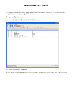


© Copyright 2026