
Document 310429
Table Contents Page i Table of Contents 5. Nonresidential Indoor Lighting .................................................................................................. 1 5.1 Overview............................................................................................................................ 2 5.1.1 Significant Changes in 2013 ...................................................................................... 2 5.1.2 Scope and Application ............................................................................................... 2 5.1.3 Mandatory Measures ................................................................................................. 3 5.1.4 Lighting Power Allotments .......................................................................................... 3 5.1.5 Forms, Plan Check, Inspection, Installation, and Acceptance Tests ......................... 4 5.1.6 The Lighting Compliance Process ............................................................................. 5 5.2 General Requirements for Mandatory Measures .............................................................. 7 5.2.1 Residential Function Areas in Nonresidential Buildings ............................................. 7 5.2.2 Certification Requirements for Manufactured Lighting Equipment, Products, and Devices ...................................................................................................................... 8 5.2.3 California Appliance Efficiency Regulations (Title 20) ................................................ 9 5.2.4 Requirements for Lighting Control Devices and Systems, Ballasts, and Luminaires . 9 5.3 Mandatory Requirements for Classification of Installed Luminaires and Determination of Luminaire Power ............................................................................................................. 16 5.4 Mandatory Lighting Controls............................................................................................ 22 5.4.1 Area Lighting Controls. ............................................................................................. 22 5.4.2 Multi-Level Lighting Controls. ................................................................................... 23 5.4.3 Automatic Shut-OFF Controls .................................................................................. 26 5.4.4 Mandatory Automatic Daylighting Controls .............................................................. 31 5.4.5 Demand Responsive Controls. ................................................................................ 39 5.4.6 Lighting Control Acceptance Requirements (§130.4) .............................................. 41 5.4.7 Lighting Certificate of Installation Requirements ...................................................... 42 5.4.8 Summary of Mandatory Controls ............................................................................. 43 5.5 Prescriptive Daylighting Requirements............................................................................ 45 5.5.1 Prescriptive Daylighting Control Requirements ........................................................ 45 5.5.2 Prescriptive Daylighting Requirements for Large Enclosed Spaces ........................ 45 5.6 General Requirements for Prescriptive Lighting .............................................................. 51 5.6.1 Requirements for a Compliant Building .................................................................... 51 5.6.2 Calculation of Actual Indoor Lighting Power ............................................................ 51 5.6.3 Portable Office Lighting ............................................................................................ 51 5.6.4 Two interlocked lighting systems ............................................................................. 52 2013 Nonresidential Compliance Manual January 2014 Page ii Table Contents 5.6.5 Reduction of wattage through controls (PAFs).........................................................52 5.6.6 Lighting Wattage Not Counted Toward Building Load .............................................56 5.7 Prescriptive Methods for Determining Lighting Power Allowances ................................. 58 5.7.1 Complete Building Method .......................................................................................58 5.7.2 Area Category Method .............................................................................................61 5.7.3 Tailored Method .......................................................................................................68 5.8 Performance Approach....................................................................................................91 5.9 Additions and Alterations .................................................................................................92 5.9.1 Summary ..................................................................................................................92 5.9.2 Additions ..................................................................................................................92 5.9.3 Alterations – General Information.............................................................................92 5.9.4 Alterations – Performance Approach .......................................................................95 5.9.5 Alterations – Prescriptive Approach .........................................................................95 5.9.6 Luminaire Modifications-in-Place .............................................................................97 5.9.7 Lighting Wiring Alterations .....................................................................................100 5.10 Indoor Lighting Compliance Documents........................................................................103 5.10.1 Overview ................................................................................................................103 5.10.2 Submitting Compliance Documentation .................................................................103 5.10.3 Separately Documenting Conditioned and Unconditioned Spaces ........................ 103 5.10.4 Varying Number of Rows per Document ................................................................ 103 5.10.5 Compliance Documentation Numbering.................................................................103 5.10.6 Certificate of Compliance Documents ....................................................................104 5.10.7 Instructions for Completing Nonresidential Indoor Lighting Certificates of Compliance ............................................................................................................104 5.10.8 Certificates of Installation .......................................................................................128 5.10.9 Instructions for filling out the Certificates of Installation .........................................129 5.10.10 Certificate of Acceptance .......................................................................................131 2013 Nonresidential Compliance Manual January 2014 Nonresidential Indoor Lighting – Overview 5. Page 5-1 Nonresidential Indoor Lighting This chapter covers the requirements for indoor lighting design and installation, including controls, for both conditioned and unconditioned nonresidential buildings. It is addressed primarily to lighting designers or electrical engineers and to enforcement agency personnel responsible for lighting and electrical plan checking and inspection. Chapter 6 addresses nonresidential outdoor lighting applications, and Chapter 7 addresses indoor and outdoor sign lighting. Indoor lighting is one of the single largest consumers of energy (kilowatt-hours) in a commercial building, representing about a third of electricity use. The objective of the Standards is the effective reduction of this energy use, without compromising the quality of lighting or task work. The Standards are the result of the involvement of many representatives of the lighting design and manufacturing community, and of enforcement agencies across the state. A great deal of effort has been devoted to making the lighting requirements practical and realistic. Figure 5-1 – Lighting Energy Use Lighting accounts for about one third of commercial building electricity use in California. Source California Commercial End-Use Survey (CEUS), March 2006, California Energy Commission No. 400-2006-005 2013 Nonresidential Compliance Manual January 2014 Page 5-2 5.1 Nonresidential Indoor Lighting – Overview Overview The primary mechanism for regulating indoor lighting energy under the Standards is to limit the allowed lighting power in watts installed in the building. Other mechanisms require basic equipment efficiency, and require that the lighting is controlled to permit efficient operation. 5.1.1 Significant Changes in 2013 The significant changes for nonresidential indoor lighting in the 2013 update to the Standards include: • An increased number of steps for mandatory multi-level lighting controls. • New requirements for bi-level occupancy controls in some spaces. • In all buildings except offices, lighting must be shut off completely during unoccupied times. • Automatic daylighting controls are mandatory in all primary daylit zones with at least 120W of installed load, with fewer exceptions. • The threshold for when alterations must comply with the Standards has been reduced from when 50% of the luminaires in a room are altered, to when 10% of the luminaires in a room are altered. • A new category of alteration called “luminaire modifications in place” has been added. • Demand responsive control systems are required in all buildings 10,000 square feet or larger. 5.1.2 Scope and Application • The nonresidential indoor lighting Standards apply to nonresidential, high-rise residential (except dwelling units), and hotel/motel occupancies (except guest rooms). • The nonresidential indoor lighting Standards are the same for unconditioned spaces as they are for conditioned spaces, except that trade-offs are not allowed between unconditioned and conditioned spaces. • Some function areas within a few buildings typically classified as low-rise residential are required to comply with the nonresidential indoor lighting Standards, such as the common area in a low-rise multi-family residential building when there is greater than 20% common area in the building (§150.0(k)12). • Some function areas in nonresidential, high-rise residential, and hotel/motel occupancies are required to comply with the low-rise residential lighting Standards (section 5.2.1 of this chapter). 2013 Nonresidential Compliance Manual January 2014 Nonresidential Indoor Lighting – Overview Page 5-3 • The low-rise residential lighting Standards are covered in chapter 6 of the 2013 Residential Compliance Manual. • The 2013 Standards require that hotel/motel guest rooms have captive card key controls or occupancy sensing controls that controls lighting, half of the receptacles and HVAC equipment. For details of the HVAC requirements, see (§120.2(e)4). The lighting requirements include the following for hotel/motel guest rooms: a. Shall have captive card key controls, occupancy sensing controls, or other automatic controls that automatically turn off the lighting within 30 minutes after the guest room has been vacated (§130.1(c)8). There is an exception to this requirement. One high efficacy luminaire (as defined in TABLE 150.0-A or 150.0-B) that is switched separately and where the switch is located within 6 feet of the entry door is not required to automatically turn off within 30 minutes. b. For hotel and motel guest rooms at least one-half of the 120-volt receptacles in each guest room shall be controlled receptacles that comply with §130.5(d)1, 2, and 3. Electric circuits serving controlled receptacles shall have captive card key controls, occupancy sensing controls, or automatic controls such that, no longer than 30 minutes after the guest room has been vacated, the power is switched off (§130.5(d)). • Qualified historic buildings are not covered by the Standards, as stated in exception 1 to §100.0(a). Historic buildings are regulated by the California Historical Building Code (Title 24, Part 8 or California Building Code, Title 24, Part 2, Volume I, Chapter 34, Division II).. However, non-historical components of the buildings, such as new or replacement mechanical, plumbing, and electrical (including lighting) equipment, additions and alterations to historic buildings, and new appliances in historic buildings may need to comply with the Standards and Appliance Efficiency Regulations, as well as other codes. For more information about energy compliance requirements for Historic Buildings, see section 1.7.1, Building Types Covered, in Chapter 1 of this manual. 5.1.3 Mandatory Measures §130.0 through §130.4 Some requirements in the nonresidential lighting Standards are classified as “Mandatory Measures,” because they are required to be met regardless of the compliance approach used. There are no alternate options for the Mandatory Measures. There are no options to not comply with the Mandatory Measures. Details about the Mandatory Measures are in sections 5.2 through 5.4 of this chapter. 5.1.4 Lighting Power Allotments Lighting Power Allotments are the established maximum lighting power (typically watts per square foot) that can be installed based upon the compliance approach used, the building type, and the type of primary function area. Lighting Power Allotments for an application are determined by one of the following four compliance approaches: 2013 Nonresidential Compliance Manual January 2014 Page 5-4 Nonresidential Indoor Lighting – Overview A. Prescriptive Approach – Complete Building Method: applicable when the entire building’s lighting system is designed and permitted at one time, and when at least 90 percent of the building is one primary nonresidential building type of use, as defined specifically in §100.1(b). In some cases, the complete building method may be used for an entire nonresidential building type tenant space in a multi-tenant building. A single Lighting Power Density Allotment value governs the entire building §140.6(b)1. See section 5.5.1. B. Prescriptive Approach – Area Category Method: applicable for any permit situation, including tenant improvements. Lighting power values are assigned to each of the major function areas of a building (offices, lobbies, corridors, etc., as defined specifically in §100.1(b))This approach provides some flexibility to accommodate special tasks, by providing an additional power allowance under some circumstances. See section 5.5.2. C. Prescriptive Approach – Tailored Method: applicable for a limited number of defined primary function areas when additional flexibility is needed to accommodate special task lighting needs in specific task areas. Several layers of lighting power allotments may be allowed depending on the space and tasks. Lighting power allotments are determined room-by-room and task-by-task. When using the Tailored method, the Area Category Method shall be used for the remainder of the interior lighting in the building. See section 5.5.3. D. Performance Approach: applicable when the designer uses an Energy Commissioncertified compliance software program to demonstrate that the proposed building's energy consumption, including lighting power, meets the energy budget. The performance approach incorporates one or more of the three previous methods which set the appropriate Lighting Power Allotment used in calculating the building’s custom energy budget. The Performance Approach allows energy allotments to be traded between mechanical, envelope, and lighting systems. Such trade-offs can only be made when permit applications are sought for those systems involved. For example, under the performance approach, a building with an envelope or mechanical system that is more efficient than the prescriptive efficiency requirements may be able to meet the energy budget for a standard designed building with a bit more lighting power than allowed under the three prescriptive lighting approaches. No additional lighting power allotment is gained by using the Performance Method when not trading energy from the mechanical or envelope systems. Therefore, the Performance approach is not applicable to lighting compliance alone. The Performance Approach may only be used to model the performance of lighting systems that are covered under the building permit application. See section 5.6 and Chapter 11 of this document. 5.1.5 Forms, Plan Check, Inspection, Installation, and Acceptance Tests Chapter 2 of this manual provides an overview of the documentation requirements and the process of complying with the Standards. Additionally, acceptance requirements are covered in section 5.7.3, certificates of installation are explained in section, 5.2.6, and lighting plan check documents are covered in section 5.10.1 of this chapter. 2013 Nonresidential Compliance Manual January 2014 Nonresidential Indoor Lighting – Overview Page 5-5 This process includes providing documentation that shows a building complies with all of the pertinent requirements of the Standards. After this is reviewed and approved during plan check, construction may begin. During and after construction, installers must post or submit Certificate of Installations to verify that all equipment has met the requirements listed in the Certificate of Compliance; and there are periodic field inspections to assure that all required energy features are installed. At the end of construction, acceptance tests are performed on HVAC and lighting controls to assure they are installed and work correctly. If inspections or acceptance testing uncover systems that are not installed as shown in the plans and documentation, or are found not to be operating correctly through acceptance testing, these defects have to be fixed before the building is approved. Once approved by the code official as complying with all the building code requirements including the energy code, the building receives a Certificate of Occupancy. Comply with Mandatory Measures Select Method of Compliance Calculate Actual Lighting Power Prescriptive Methods Performance NO Tailored Adjusted Actual Lighting Power Area Category Revise the lighting design Complete Building Adjust Lighting Power using applicable Control Credits Allowed Lighting Power Is Adjusted Actual Lighting Power ≤ Allowed Lighting Power? YES Lighting complies Figure 5-2 – Lighting Compliance Flowchart 5.1.6 The Lighting Compliance Process Figure 5-2, above, shows the process for complying with the nonresidential indoor lighting Standards. 2013 Nonresidential Compliance Manual January 2014 Page 5-6 Nonresidential Indoor Lighting – Overview Following the left side of Figure 5-2: First, the Mandatory Measures are required regardless of the compliance method selected (See sections 5.2 through 5.4). Next, select a method for complying with the Standards. There are three Prescriptive compliance methods: Complete Building Method, Area Category Method, and Tailored Method (See sections 5.6 through 5.8); and there is a Performance Method (See section 5.8), where compliance is demonstrated using one of the software programs that has been approved by the Energy Commission. This process will determine how many watts of lighting power are allowed to be installed in the building. Following the right side of Figure 5-2: First, calculate the actual lighting power installed by totaling all of the lighting installed in the building (See section 5.3). Next, subtract lighting control credits (See section 5.6). This process will demonstrate the adjusted actual watts of lighting power that has been installed in the building. Conclusion If the lighting power that is allowed to be installed in the building, is equal to or greater than the adjusted actual watts installed, than the lighting in the building complies with the Standards. If the lighting in the building does not comply with the Standards, then either the lighting power will need to be reduced, or additional lighting credits will need to be acquired. 2013 Nonresidential Compliance Manual January 2014 Nonresidential Indoor Lighting – General Requirements for Mandatory Measures 5.2 Page 5-7 General Requirements for Mandatory Measures Some requirements in the nonresidential lighting Standards are classified as “Mandatory Measures,” because they are required regardless of the compliance approach used. There are no alternate options for substituting the Mandatory Measures. There are no options to not comply with the Mandatory Measures. It is the responsibility of the designer to specify products that meet these requirements. It is the responsibility of the installer to comply with all of the mandatory requirements, even if the plans mistakenly do not. Code enforcement officials, in turn, must check that the mandatory features and specified devices are installed. The mandatory measures for nonresidential indoor lighting include the following: • Some functional areas in nonresidential buildings are required to comply with the low-rise residential lighting Standards (Section 5.2.2 of this chapter) • Certification of manufactured lighting control devices and systems, ballasts, and luminaires (Section 5.2.2 of this chapter) • Compliance with the California Appliance Efficiency Regulations (Title 20) (Section 5.2.2 of this chapter) • Rules for how luminaires shall be classified according to technology, and how installed lighting power shall be determined (Section 5.3 of this chapter) • Indoor lighting controls that shall be installed, which include: Area controls, multilevel controls, automatic shut-OFF controls, daylighting controls, and demand responsive controls (Section 5.4 of this chapter) • Lighting control acceptance testing required (Section 5.4.6 of this chapter) • Lighting control Certificate of Installations required (Section 5.4.7 of this chapter) • Although not related exclusively to lighting, there are mandatory measures for electrical power distribution systems, which include the following: Disaggregation of electrical circuits; voltage drop; circuit controls for 120-volt receptacles; specifications for demand responsive controls and equipment; and. specifications for energy management control systems. See Chapter 8 of this manual for additional information about mandatory measures for electrical power distribution systems. 5.2.1 Residential Function Areas in Nonresidential Buildings The following function areas in nonresidential, high-rise residential, and hotel/motel occupancies are required to comply with the low-rise residential lighting Standards (§130.0(b)). 1. High-rise residential dwelling units. 2. Outdoor lighting that is attached to a high-rise residential or hotel/motel building, and is separately controlled from the inside of a dwelling unit or guest room. 3. Fire station dwelling accommodations. 4. Hotel and motel guest rooms. 2013 Nonresidential Compliance Manual January 2014 Page 5-8 Nonresidential Indoor Lighting – General Requirements for Mandatory Measures 5. Dormitory and senior housing dwelling accommodations. In buildings containing these residential type functional areas, all other functional areas, such as common areas, shall comply with the applicable nonresidential lighting Standards. 5.2.2 Certification Requirements for Manufactured Lighting Equipment, Products, and Devices §100.0(h) The Standards do not require a builder, designer, owner, operator, or enforcing agency to test any certified device to determine its compliance with minimum specifications or efficiencies adopted by the Commission. The Standards limit the installation of manufactured lighting equipment, products, and devices as follows: A. Lighting items that are regulated by the Title 20 Appliance Efficiency Regulations Installation shall be limited to those that have been certified to the Energy Commission by their manufacturer, pursuant to the provisions of Title 20 Cal. Code of Regulations, §1606, to meet or exceed minimum specifications or efficiencies adopted by the Commission. Once a device is certified, it will be listed in the Directory of Automatic Lighting Control Devices, which is available from the link below: http://www.energy.ca.gov/appliances/database/ Call the Energy Hotline at 1-800-772-3300 to obtain more information. B. Lighting products required to be Certified to the Energy Commission according to Title 24 These products are not regulated by Title 20. Installation shall be limited to those certified by the manufacturer in a declaration, executed under penalty of perjury under the laws of the State of California, that all the information provided pursuant to the certification is true, complete, accurate and in compliance with all applicable provisions of The Standards; and if applicable that the equipment, product, or device was tested under the applicable test method specified in The Standards. C. Lighting products required to be listed in directories or certified by someone other than the Energy Commission Installation shall limited to those that comply with the following provisions. The certification status of any such manufactured device shall be confirmed only by reference to: 1. A directory published or approved by the Commission; or 2. A copy of the application for certification from the manufacturer and the letter of acceptance from the Commission staff; or 3. Written confirmation from the publisher of a Commission-approved directory that a device has been certified; or 4. A Commission-approved label on the device. 2013 Nonresidential Compliance Manual January 2014 Nonresidential Indoor Lighting – General Requirements for Mandatory Measures Page 5-9 5.2.3 California Appliance Efficiency Regulations (Title 20) §110.1 Any appliance regulated by the Appliance Efficiency Regulations, Title 20 California Code of Regulations, §1601 et seq., may be installed only if the appliance fully complies with those regulations. The Title 20 regulations apply to appliances that are sold or offered for sale in California, except those sold wholesale in California for final retail sale outside the state and those designed and sold exclusively for use in recreational vehicles or other mobile equipment. Lighting products regulated by the California Appliance Efficiency Regulations (Title 20) must be certified to the Energy Commission by the manufacturer before they can be sold or offered for sale in California, or before they can be specified on California building projects subject to the Standards. The California Appliance Efficiency Regulations include requirements for both federally-regulated appliances and non-federally-regulated appliances. 5.2.4 Requirements for Lighting Control Devices and Systems, Ballasts, and Luminaires §110.9 Performance specifications for most lighting controls have been adopted into the California Title 20 Appliance Efficiency Regulations. To be legally sold or offered for sale in California, stand-alone lighting controls covered by the Appliance Regulations must be tested and certified to the California Energy Commission that they comply with the requirement in the standard. However, there are many networked lighting control systems that can be programmed to do many of the same functions as the certified stand-alone lighting controls. This section describes the requirements for lighting controls. Stand-alone lighting controls must comply with Title 20 and be in the Appliance Regulation database. Built up lighting controls have to comply with the functional requirements in Title 20 standards. The capabilities of these controls are exercised in the acceptance tests required by §130.4 §110.9 has minimum performance requirements for these self-contained lighting control devices which are not covered by the Title 20 appliance efficiency standards ; field assembled lighting control systems; line-voltage track lighting integral current limiters; supplementary overcurrent protection panels for use with track lighting; ballasts for residential recessed compact fluorescent luminaires; and qualifications for residential high efficacy LED luminaires. The requirements in §110.9 for ballasts used in residential recessed compact fluorescent luminaires, and for residential high efficacy LED luminaires, do not apply to most nonresidential lighting function areas, except for inside dwelling units of high-rise residential, hotel/motel, fire stations, and dormitory/senior housing. A. Definition of Self-Contained Lighting Control Devices These are defined by the Standards as unitary lighting control modules that require no additional components to be fully functional lighting controls. Most self-contained lighting controls required to be installed for compliance with the Standards are required to be certified by the manufacturer according to the Title 20 Appliance Efficiency Regulations The following lighting controls are required to be certified to the Energy Commission in accordance with Title 20 (§110.9(b)1-4).: 2013 Nonresidential Compliance Manual January 2014 Page 5-10 Nonresidential Indoor Lighting – General Requirements for Mandatory Measures 1. Time-Switch Lighting Controls • Automatic Time-Switch Controls • Astronomical Time-Switch Controls • Multi-Level Astronomical Time-Switch Controls • Outdoor Astronomical Time-Switch Controls 2. Daylighting Controls • Automatic Daylight Controls • Photo Controls 3. Dimmers 4. Occupant Sensing Controls • Occupant Sensors • Motion Sensors • Vacancy Sensors B. Requirements for Miscellaneous Lighting Controls Regulated by Title 24 Lighting controls regulated by Title 24, but not regulated by the Title 20 Appliance Efficiency Regulations, shall meet the following requirements: 1. Part-Night Outdoor Lighting Control (§110.9(b)5) Although Part-Night outdoor lighting controls do not apply to nonresidential indoor lighting Standards, information about these controls has been placed in this chapter so as to not exclude any regulated control types from this discussion. A Part Night Outdoor Lighting Control is defined by the Standards as a time or occupancy-based lighting control device or system that is programmed to reduce or turn off the lighting power to an outdoor luminaire for a portion of the night. (Note that this lighting control does not apply to nonresidential indoor lighting Standards). a. The Part-Night Outdoor Lighting Control is not required to be certified by the manufacturer to the Energy Commission. b. The requirements for a Part-Night Outdoor Lighting Control are as follows: i. Be able to accurately predict sunrise and sunset within +/- 15 minutes and timekeeping accuracy within five minutes per year; and ii. Be able to setback or turn off lighting at night as required in §130.2(c), by means of a programmable timeclock or motion sensing device; and iii. When the setback or turning off is controlled with a timeclock, shall be capable of being programmed to allow the setback or turning off of the lighting to occur from any time at night until any time in the morning, as determined by the user. 2. Track lighting integral current limiter (§110.9(c)) 2013 Nonresidential Compliance Manual January 2014 Nonresidential Indoor Lighting – General Requirements for Mandatory Measures Page 5-11 A track lighting current limiter is used to limit the rated power that can go through a section of track lighting. Without the current limiter, the “installed” wattage of long section of track could be excessive and use up all of the allotted lighting power for a space. With track lighting and a current limiter, one can space the track heads far apart and use high efficacy sources in the track heads so it is possible to stay below the rated wattage of the current limiter. If the wattage served by the current limiter exceeds the rated wattage of the current limiter, the current limiter turns off the current to the controlled lighting. A track lighting integral current limiter shall be recognized for compliance with the Standards only for line-voltage track lighting systems, and only if it meets all of the following requirements: a. Shall be certified to the Energy Commission by the manufacturer in accordance with the requirements in §110.9(c); and b. Before a Line-Voltage Track Lighting Integral Current Limiter will be recognized for compliance with the lighting requirements in Part 6 of Title 24, the person who is eligible under Division 3 of the Business and Professions Code to accept responsibility for the construction or installation of features, materials, components, or manufactured devices shall sign and submit the Certificate of Installation. c. If any of the requirements fail the Line-Voltage Track Lighting Integral Current Limiter installation test, the Line-Voltage Track Lighting Integral Current Limiter for determining installed lighting power shall not be used for compliance with Title 24; and d. Shall be manufactured so that the current limiter housing is used exclusively on the same manufacturer's track for which it is designed; and e. Shall be designed so that the current limiter housing is permanently attached to the track so that the system will be irreparably damaged if the current limiter housing were to be removed after installation into the track. Methods of attachment may include but are not limited to one-way barbs, rivets, and oneway screws; and f. Shall employ tamper resistant fasteners for the cover to the wiring compartment; and g. Shall have the identical volt-ampere (VA) rating of the current limiter, as the system is installed and rated for compliance with the Standards clearly marked on all of the following places: i. So that it is visible for the building officials’ field inspection without opening coverplates, fixtures, or panels; and ii. Permanently marked on the circuit breaker; and iii. On a factory-printed label that is permanently affixed to a nonremovable base-plate inside the wiring compartment. 2013 Nonresidential Compliance Manual January 2014 Page 5-12 Nonresidential Indoor Lighting – General Requirements for Mandatory Measures h. Shall have a conspicuous factory installed label permanently affixed to the inside of the wiring compartment warning against removing, tampering with, rewiring, or bypassing the device; and i. Each electrical panel from which track lighting integral current limiters are energized shall have a factory printed label permanently affixed and prominently located, stating the following: "NOTICE: Current limiting devices installed in track lighting integral current limiters connected to this panel shall only be replaced with the same or lower amperage. Adding track or replacement of existing current limiters with higher continuous ampere rating will void the track lighting integral current limiter certification, and will require re-submittal of compliance documentation to the enforcement agency responsible for compliance with the California Title 24, Part 6 Building Energy Efficiency Standards.” 3. Track Lighting Supplementary Overcurrent Protection Panel (§110.9(d)) A Track Lighting Supplementary Overcurrent Protection Panel is a subpanel that contains current limiters for use with only multiple track lighting circuits. A Track Lighting Supplementary Overcurrent Protection Panel shall be used only for line-voltage track lighting and shall be recognized for compliance with the Standards only if it meets all of the following requirements: a. Before a Track Lighting Supplementary Overcurrent Protection Panel will be recognized for compliance with the lighting requirements in Part 6 of Title 24, the person who is eligible under Division 3 of the Business and Professions Code to accept responsibility for the construction or installation of features, materials, components, or manufactured devices shall sign and submit the Certificate of Installation. b. If any of the requirements in the Certificate of Installation fail the installation tests, the Track Lighting Supplementary Overcurrent Protection Panel shall not be recognized by the Standards for determining installed lighting power. c. Shall be listed in accordance with Article 100 of the California Electric Code. d. Shall be used only for line voltage track lighting. No other lighting or building power shall be used in a Supplementary Overcurrent Protection Panel, and no other lighting or building power shall be recognized for compliance with the Standards by using a Supplementary Overcurrent Protection Panel e. Be permanently installed in an electrical equipment room, or permanently installed adjacent to the lighting panel board providing supplementary overcurrent protection for the track lighting circuits served by the supplementary over current protection pane; and f. Shall have a permanently installed label that is prominently located stating the following: "NOTICE: This Panel for Track Lighting Energy Code Compliance Only. The overcurrent protection devices in this panel shall only be replaced with the same or lower amperage. No other overcurrent protective device shall 2013 Nonresidential Compliance Manual January 2014 Nonresidential Indoor Lighting – General Requirements for Mandatory Measures Page 5-13 be added to this panel. Adding to, or replacement of existing overcurrent protective device(s) with higher continuous ampere rating, will void the panel listing and require re-submittal of compliance documentation to the enforcement agency responsible for compliance with the California Title 24, Part 6 Building Energy Efficiency Standards.” C. Requirements for Lighting Control Systems Lighting Control Systems are defined by the Standards as requiring two or more components to be installed in the building to provide all of the functionality required to make up a fully functional and compliant lighting control. Lighting control systems may be installed for compliance with lighting control requirements in the Standards providing they meet all of the following requirements: 1. A lighting control system shall comply with all requirements listed below; and all components of the system considered together as installed shall meet all applicable requirements for the lighting control application for which they are installed as required in §130.0 through §130.5, §140.6 through §140.8, §141.0, and §150(k). 2. Before a Lighting Control System (including an EMCS) can be recognized for compliance with the lighting control requirements in Part 6 of Title 24, the person who is eligible under Division 3 of the Business and Professions Code to accept responsibility for the construction or installation of features, materials, components, or manufactured devices shall sign and submit an Certificate of Installation. 3. If any of the requirements in the Certificate of Installation fail the installation tests, the Lighting Control System (or EMCS) shall not be recognized for compliance with Title 24. 4. If there are indicator lights that are integral to a lighting control system, they shall consume no more than one watt of power per indicator light. 5. A lighting control system shall meet all of the functional requirements in the Title 20 Appliance Efficiency Regulations for the comparable self-contained lighting control devices For example, if a lighting control system is installed to comply with the Title 24 requirements for an occupancy sensor, then the lighting control system shall comply with all of the requirements for an occupancy sensor in Title 20. If that same lighting control system is also installed to comply with the Title 24 requirements for a daylighting control, then it shall also comply with all of the requirements for a daylighting control in Title 20. Each of these functions shall be documented in the Certificate of Installation (see item 2 above). 6. If the system is installed to function as a partial-on or partial-off occupant sensor, the installation may be made up of a combination of single or multi-level Occupant, Motion, or Vacancy Sensor Controls, provided that the components installed to comply with manual-on requirements shall not be capable of conversion by the user from manual-on to automatic-on functionality. 2013 Nonresidential Compliance Manual January 2014 Page 5-14 Nonresidential Indoor Lighting – General Requirements for Mandatory Measures Savings compared to single‐ level automatic‐on control User manually switches on remaining lights if required Lighting power System automatically switches on some of the lights Time delay System automatically switches off all the lights Time Occupant enters the space Occupant leaves the space Figure 5-3 Functional Diagram for Partial-ON Occupant Sensor Savings compared to simple time‐schedule control System automatically switches on second stage of lights Lighting power System automatically switches on first stage of lights, on a time schedule Time delay System automatically switches off second stage of lights System automatically switches off first stage of lights, on a time schedule Time Occupant enters the space Occupant leaves the space Figure 5-4 Functional Diagram for Partial-OFF Occupant Sensor D. Requirements for Residential Luminaires The following requirements apply only to residential luminaires: 2013 Nonresidential Compliance Manual January 2014 Nonresidential Indoor Lighting – General Requirements for Mandatory Measures Page 5-15 1. The requirements for residential luminaires apply to very few nonresidential buildings; only when installed in specifically defined residential function areas that are within a nonresidential building. (See section 5.1.1 C of this chapter) 2. Residential High Efficacy Light Emitting Diode (LED) Lighting. There are no requirements for certifying nonresidential luminaires in accordance with the Title 24 Standards. However, there are some LED luminaires and LED light engines that are designed to be installed in either residential or nonresidential applications. Following are requirements for classifying an LED luminaire as high efficacy for compliance with the residential lighting Standards: a. To qualify as high efficacy for compliance with the residential lighting Standards in §150.0(k), a residential LED luminaire or LED light engine shall be certified to the Energy Commission according to the requirements in Reference Joint Appendix JA-8. LED lighting that is not certified to the Energy Commission shall be classified as low efficacy for compliance with §150.0(k), regardless of its actual efficacy. Appendix JA-8 requirements for High Efficacy LED luminaires • Manufactured for use in residential applications • Contain a LED light engine (not screw base lamp) that is hard wired, uses a quick connect connector or GU-24 base. • CRI (color rendering index) ≥ 90. • CCT (color correlated temperature) between 2700k and 4000k for indoor lighting and between 2700k and 5000k for outdoor lighting • The efficacy of the integral LED luminaire or LED light engine, when tested in accordance with IES LM-79-2008, shall be equal to or greater than the efficacies contained in TABLE JA-8. TABLE 5 - 1 (Table JA-8 in the Reference appendix) Power Rating per Integral LED Luminaire, or per LED Lighting Engine Under Test 5 watts or less Over 5 watts to 15 watts Over 15 watts to 40 watts Over 40 watts Minimum Efficacy (Lumens per Watt) 30 45 60 90 High Efficacy Qualification Requirements for Luminaires or Light Engines Using LED Light Sources 3. Ballasts for Residential Recessed Luminaires. To qualify as high efficacy for compliance with the residential lighting Standards in §150.0(k), any compact fluorescent lamp ballast in a residential recessed luminaire shall meet all of the following conditions, in accordance with §110.9(f): b. a. Be rated by the ballast manufacturer to have a minimum rated life of 30,000 hours when operated at or below a specified maximum case temperature. This maximum ballast case temperature specified by the ballast manufacturer shall not be exceeded when tested in accordance to UL 1598 §19.15; and Have a ballast factor of not less than 0.90 for non-dimming ballasts and a ballast factor of not less than 0.85 for dimming ballasts. 2013 Nonresidential Compliance Manual January 2014 Page 5-16 Nonresidential Indoor Lighting – Mandatory Requirements for Classification of Installed Luminaires and Determination of Luminaire Power 5.3 Mandatory Requirements for Classification of Installed Luminaires and Determination of Luminaire Power §130.0(c); NA8 The requirements for classifying the type of lighting technology of a luminaire, and the requirements for determining how many watts of power is used per luminaire, are contained in §130.0(c). While residential luminaires are required to be classified as high or low efficacy, there are no requirements to classify nonresidential luminaires as high or low efficacy, Following are the requirements in §130.0(c) for determining luminaire classification and power: 1. Manufacturer labeling of luminaires. Following are the requirements for labeling luminaires: a. The maximum relamping rated wattage of a luminaire shall be listed on a permanent, pre-printed, factory-installed label, as specified by UL 1574, 1598, 2108, or 8750, as applicable; and b. The factory-installed maximum relamping rated wattage label shall not consist of peeloff or peel-down layers or other methods that allow the rated wattage to be changed after the luminaire has been shipped from the manufacturer. Peel-down labels may be used only for a luminaire meeting ALL of the following requirements: a. It can accommodate a range of lamp wattages without changing the luminaire housing, ballast, transformer or wiring, and b. It has a single lamp, and c. It has an integrated ballast or transformer, and d. Peel-down labels must be layered such that the rated wattage reduces as successive layers are removed, and e. The Standards will recognize peel-down labels only for the following three types of luminaires, and only when they meet all of the following conditions: i. High intensity discharge luminaires, having an integral electronic ballast, with a maximum relamping rated wattage of 150 watts. ii. Low-voltage luminaires (this shall not apply to low voltage track systems), ≤ 24 volts, with a maximum relamping rated wattage of 50 watts. iii. Compact fluorescent luminaires, having an integral electronic ballast, with a maximum relamping rated wattage of 42 watts. 2. Luminaires with line voltage lamp holders not containing permanently installed ballasts are always classified as incandescent luminaires. The wattage of such luminaires shall be determined as follows: 2013 Nonresidential Compliance Manual January 2014 Nonresidential Indoor Lighting – Mandatory Requirements for Classification of Installed Luminaires and Determination of Luminaire Power Page 5-17 a. The maximum relamping rated wattage of the luminaire; and b. For recessed luminaires with line-voltage medium screw base sockets, wattage shall not be less than 50 watts per socket. For example, if a recessed luminaire has a relamping rated wattage on a permanent, pre-printed, factory-installed label of 30 watts, it shall be counted as 50 watts; if a recessed luminaire has a relamping rated wattage of 90 watts, it shall be counted as 90 watts. Peel-down labels are never recognized for any type of incandescent luminaire. 3. Luminaires and luminaire housings designed to accommodate a variety of trims or modular components that allow the conversion between incandescent and any other lighting technology without changing the luminaire housing or wiring shall be classified as incandescent. 4. Screw-based adaptors shall not be used to convert an incandescent luminaire to any type of non-incandescent technology. Screw-based adaptors, including screw-base adaptors classified as permanent by the manufacturer, shall not be recognized for compliance with the Standards. 5. Luminaires and luminaire housings manufactured with incandescent screw base sockets shall be classified only as incandescent. Field modifications, including hard wiring of an LED module, shall not be recognized as converting an incandescent luminaire or luminaire housing to a non-incandescent technology for compliance with the Standards. 6. Luminaires with permanently installed or remotely installed ballasts will be either fluorescent or high intensity discharge. Wattage shall be determined as follows: a. Wattage shall be the operating input wattage of the rated lamp/ballast combination published in ballast manufacturer’s catalogs based on independent testing lab reports as specified by UL 1598. b. Replacement of lamps in a luminaire manufactured or rated for use with linear fluorescent lamps, with linear lamps of a different technology such as linear LED lamps, shall not be recognized as converting the fluorescent luminaire to a different technology for compliance with the Standards. 7. The wattage of line-voltage lighting track and plug-in busway which allows the addition or relocation of luminaires without altering the wiring of the system shall be determined by one of the following methods: a. There is only one option for line voltage busway and track rated for more than 20 amperes. Wattage shall be the total volt-ampere rating of the branch circuit feeding the busway and track. b. There are four options for determining the wattage of line voltage busway and track rated for 20 amperes or less, as follows: i. Line Voltage Track Lighting Option 1: The volt-ampere rating of the branch circuit feeding the track or busway; or 2013 Nonresidential Compliance Manual January 2014 Page 5-18 Nonresidential Indoor Lighting – Mandatory Requirements for Classification of Installed Luminaires and Determination of Luminaire Power ii. Line Voltage Track Lighting Option 2 The higher of: iii. • The rated wattage of all of the luminaires included in the system, where luminaire classification and wattage is determined according to the applicable provisions in §130.0(c), or • 45 watts per linear foot; or Line Voltage Track Lighting Option 3 When using a Line-Voltage Track Lighting Integral Current Limiter, the higher of: • The volt-ampere rating of an integral current limiter controlling the track or busway, or • 12.5 watts per linear foot of track or busway. An Integral current limiter shall be certified to the Energy Commission in accordance with §110.9, and shall comply with the Lighting Control Installation Requirements. Before a Line-Voltage Track Lighting Integral Current Limiter will be recognized for compliance with the lighting requirements in Part 6 of Title 24, the person who is eligible under Division 3 of the Business and Professions Code to accept responsibility for the construction or installation of features, materials, components, or manufactured devices shall sign and submit the Certificate of Installation. If any of the requirements in the Certificate of Installation fail the installation tests, the Line-Voltage Track Lighting Integral Current Limiter shall not be recognized for compliance with Title 24; or iv. Line Voltage Track Lighting Option 4 When using a dedicated track lighting supplementary overcurrent protection panel, the sum of the ampere (A) rating of all of the overcurrent protection devices times the branch circuit voltages. Track lighting supplementary overcurrent protection panels shall comply with the applicable requirements in §110.9, and shall comply with the Lighting Control Installation Requirements. Before a dedicated track lighting supplementary overcurrent protection panel will be recognized for compliance with the lighting requirements in Part 6 of Title 24, the person who is eligible under Division 3 of the Business and Professions Code to accept responsibility for the construction or installation of features, materials, components, or manufactured devices shall sign and submit the Certificate of Installation. 2013 Nonresidential Compliance Manual January 2014 Nonresidential Indoor Lighting – Mandatory Requirements for Classification of Installed Luminaires and Determination of Luminaire Power Page 5-19 If any of the requirements in the Certificate of Installation fail the installation tests, the track lighting supplementary overcurrent protection panel shall not be recognized for compliance with Title 24 8. Luminaires and lighting systems with permanently installed or remotely installed transformers. The wattage of such luminaires shall be determined as follows: a. For low-voltage luminaires that do not allow the addition of lamps, lamp holders, or luminaires without rewiring, the wattage shall be the rated wattage of the lamp/transformer combination. b. For low-voltage lighting systems, including low voltage tracks and other low-voltage lighting systems which allow the addition of lamps, lamp holders, or luminaires without rewiring, the wattage shall be the maximum rated input wattage of the transformer, labeled in accordance with item 1, or the maximum rated wattage published in transformer manufacturer’s catalogs, as specified by UL 2108. 9. Light emitting diode (LED) Luminaires, and LED Light Engine for nonresidential applications are not required to be certified to the Energy Commission. An LED light engine is a an integrated assembly comprised of LED packages (components) or LED arrays (modules), LED driver, and other optical, thermal, mechanical and electrical components . The light engine is intended to connect directly to the branch circuit through a custom connector compatible with the LED luminaire for which it was designed and does not use an ANSI standard (screw) base. LED luminaires and light engines for residential applications shall be certified to the Energy Commission in order to be classified as high efficacy. See Chapter 5 in the 2013 Residential Compliance Manual for information on classifying residential LED luminaires as high efficacy. a. The wattage of such luminaires shall be the maximum rated input wattage of the system when tested in accordance with IES LM-79-08. b. The maximum rated input wattage shall be labeled on the luminaire, light engine, or luminaire housing in accordance with §130.0(c)1. Labels only on the power supply are not sufficient for compliance with this requirement. c. An LED lamp, integrated or non-integrated type in accordance with the definition in ANSI/IES RP-16-2010, shall not be classified as a LED lighting system for compliance with The Standards. LED modules having screw-bases including screw based pig-tails, screw-based sockets, or screw-based adaptors shall not be recognized as a LED lighting system for compliance with The Standards. The intent of this requirement is to not give credit for screw based LED lamps. An ANSI/IES RP-16-2010 integrated or non-integrated LED lamp is one with a screw base. The governing wattage of a luminaire with a screw based lamp is the rated luminaire wattage and not the LED lamp. If one wants to take credit for the lower wattage afforded by a LED lamp then the luminaire must have a GU-24 socket or be a hard wired LED luminaire (i.e. contain a LED light engine) that is rated according to IES LM-79-08. d. Luminaires and luminaire housings equipped with screw-base sockets shall not be classified as a LED lighting system for compliance with The Standards. 2013 Nonresidential Compliance Manual January 2014 Page 5-20 Nonresidential Indoor Lighting – Mandatory Requirements for Classification of Installed Luminaires and Determination of Luminaire Power e. Luminaires manufactured or rated for use with low-voltage incandescent lamps, into which have been installed LED modules or LED lamps, shall not be recognized as a LED lighting system for compliance with the Standards. f. For LED lighting systems which allow the addition of luminaires or light engines without rewiring, the wattage of such luminaires shall be the maximum rated input wattage of the power supply, labeled in accordance with §130.0(c)1 or published in the power supply manufacturer’s catalog. 10. The wattage of all other miscellaneous lighting equipment shall be the maximum rated wattage of the lighting equipment, or operating input wattage of the system, labeled in accordance with §130.0(c)1, or published in manufacturer’s catalogs, based on independent testing lab reports as specified by UL 1574 or UL 1598. Lighting technologies listed in subsections 2 through 9 shall be determined in accordance with the applicable requirements in subsections 1 through 9. A. Summary of installed luminaire wattage The installed wattage of indoor lighting luminaires are calculated as follows for the various type of systems • Line voltage screw based luminaires (not including track lighting) o The maximum rated wattage of the luminaire, regardless of the wattage of the lamp that is installed. • Luminaires containing a hardwired ballasts o • • • Additional requirements for recessed luminaires: The wattage of recessed luminaires shall not be less than 50 watts The rated input wattage of the lamp/ballast Line voltage track lighting one of the following: o The larger of the rated wattage of luminaires installed on the track or 45 Watts per linear foot o The volt-amps of the circuit serving the track o The larger of the volt-amps of the integral current limiter serving the track or 12.5 Watts per linear foot of track o The volt amps of the dedicated overcurrent protection in track lighting supplementary overcurrent protection panel Low voltage luminaires with hardwired or remotely installed transformers o If the lamps cannot be replaced without rewiring the rated wattage of lamp/transformer combination o If the lamps can be replaced without rewiring (i.e. the lamps fit into a socket), the maximum rated input wattage of the transformer. Light emitting diode (LED) with “light engine” wattage is the greater of: o the maximum rated input wattage of the system when tested in accordance with IES LM-79-08, or o the labeled wattage of the luminaire 2013 Nonresidential Compliance Manual January 2014 Nonresidential Indoor Lighting – Mandatory Requirements for Classification of Installed Luminaires and Determination of Luminaire Power Page 5-21 • Screw-in LED or CFL lamps or screw-in assemblies are not recognized for their lower wattages, the rating for luminaires with screw-in lamps or assemblies is the labeled rating of the luminaire itself. B. The 2013 Title 24, Part 6 Nonresidential Appendix NA8 provides an alternate option for determining how many watts of power is used per luminaire. NA8 provides tables that contain a limited list of lamp and ballast combinations. These tables in NA8 provide an alternate voluntary option to the provision in §130(c) for determining luminaire power for any lamp and ballast combination specifically listed in NA8. Appendix NA8 is not intended to list all possible lamp and ballast combinations, and shall not to be used to determine luminaire power for any lighting system not specifically listed in NA8. When using NA8 to determine luminaire power, luminaire classification shall still be determined in accordance with §130.0(c). Lamp ballast combinations included in Appendix NA8 are: • Fluorescent U-Tubes • Fluorescent Linear Lamps T5 • Fluorescent Rapid Start T-8 • Fluorescent Eight foot T-8 High Output (HO) with Rapid Start Ballasts • High Intensity Discharge (Metal Halide and High Pressure Sodium) • 12 Volt Tungsten Halogen Lamps Including MR16, Bi-pin, AR70, AR111, PAR36 2013 Nonresidential Compliance Manual January 2014 Page 5-22 5.4 Nonresidential Indoor Lighting – Mandatory Lighting Controls Mandatory Lighting Controls §130.1 The installations of lighting controls are mandatory measures. This section contains information about lighting controls that shall be installed, regardless of the method used to comply with the lighting power requirements. All lighting controls and equipment shall comply with the applicable requirements in §110.9, and shall be installed in accordance with the manufacturer's instructions (§130.0(d)). Mandatory nonresidential indoor lighting controls include the following: 1. Area Controls. Manual controls separately controlling lighting in each area. 2. Multi-Level Controls. Providing occupants with the ability to use all of the light, some of the light, or none of the light in an area. 3. Shutoff Controls. Automatically shutting off or reducing light output of lighting when it is not needed. 4. Automatic Daylighting Controls. Separately controlling some or all of the lights in the daylight area from the lights that are not in the daylight area. 5. Demand Responsive Lighting Controls. Installing controls that are capable of receiving and automatically responding to a demand response signal. 5.4.1 Area Lighting Controls. §130.1(a) All luminaires in each area enclosed by ceiling-height partitions shall be independently controlled from luminaires in other areas, with fully functional manual ON and OFF lighting controls. EXCEPTION: The exception to the mandatory area lighting control requirements is that up to 0.2 watts per square foot of lighting in any area within a building may be continuously illuminated during occupied times to allow for emergency egress, provided that the following conditions are met: 1. The area is designated an emergency egress area on the building plans and specifications submitted to the enforcement agency under §10-103(a)2 of Part 1; and 2. The control switches for the egress lighting are not accessible to unauthorized personnel. A. Requirements for ON and OFF controls The ON and OFF lighting controls shall meet the following requirements: 1. Be readily accessible to occupants; and 2. Be operated with a manual switch that is located in the same room or area with the lighting that is being controlled by that lighting control; and 3. If controlling dimmable luminaires, be a dimmer switch that allows manual ON and OFF functionality, and is capable of manually controlling lighting through all multi-level lighting control steps that are required in §130.1(b). EXCEPTIONS: There are two exceptions to the requirements for these controls to be readily accessible and located in the same room: 2013 Nonresidential Compliance Manual January 2014 Nonresidential Indoor Lighting – Mandatory Lighting Controls Page 5-23 a. In malls, auditoriums, retail and wholesale sales floors, industrial facilities, convention centers, and arenas, the lighting control shall be located so that a person using the lighting control can see the lights or area controlled by that lighting control, or so that the lighting control for the area is annunciated. Annunciated is defined in the Standards as a type of visual signaling device that indicates the on, off, or other status of a load. b. Public restrooms having two or more stalls may use a manual switch that is not accessible to unauthorized personnel. However, all other lighting controls in accordance with §130.1 are still required. B. Interaction of Manual ON and OFF Switches with Other Lighting Controls 1. In addition to the manual area lighting controls, other lighting controls may be installed provided they do not override the functionality of controls installed in accordance with §130.1(a)1 (functionally controlled with a manual switch), §130.1(a)2 (readily accessible), or §130.1(a)4 (separately controlled lighting systems). C. Separately Controlled Lighting System In addition to the requirements in §130.1(a)1, 2, and 3: 1. General lighting shall be separately controlled from all other lighting systems in an area. 2. Floor and wall display, window display, case display, ornamental, and special effects lighting shall each be separately controlled on circuits that are 20 amps or less. 3. When track lighting is used, general, display, ornamental, and special effects lighting shall each be separately controlled. 5.4.2 Multi-Level Lighting Controls. §130.1(b) The multi-level lighting control requirements allow a room to be occupied with all of the lights turned on, part of the lights turned on, and none of the lights turned on, whether the room is occupied or not. The number of required lighting control steps varies, depending on the type of lighting technology in each installed luminaire, in accordance with Table 5-2. The uniformity requirements in Table 5-2 require that multi-level control occur per luminaire so one cannot meet this requirement by controlling alternate luminaires or alternate rows of luminaires. This requirement applies to enclosed spaces larger than 100 square feet and with a connected general lighting load greater than 0.5 W/ square foot. General lighting does not include task lights, display, or ornamental lighting. These spaces also must comply with the following: 1. Lighting shall have the required number of control steps and meet the uniformity requirements in accordance with TABLE 5-2; and 2. Multi-level lighting controls shall not override the functionally of other lighting controls required for compliance with Sections 130.1(a) [area controls], (c) [automatic shut-off controls] (d) [daylighting controls] and (e) [demand responsive controls]; and 3. In addition to the multi-level lighting controls required in Table 5-2, each luminaire shall be controlled by at least of one of the methods listed below. 2013 Nonresidential Compliance Manual January 2014 Page 5-24 Nonresidential Indoor Lighting – Mandatory Lighting Controls a. Manual dimming installed to meet the requirements of §130.1(a) b. Lumen maintenance, defined in the Standards as “a strategy used to provide a precise, constant level of lighting from a lighting system regardless of the age of the lamps or the maintenance of the luminaires.” (§100.1) c. Tuning, defined in the Standards as “the ability to set maximum light levels at a lower level than full lighting power.” (§100.1) d. Automatic daylighting control installed to meet the requirements in §130.1(d) e. Demand responsive lighting controls installed to comply with §130.1(e) NOTE: Some of the controls listed above may already need to be installed to comply with other lighting control requirements in §130.1. A. Exceptions to multi-level lighting controls The following applications are not required to comply with the requirements in Table 5-2: 1. Classrooms, with a connected general lighting load of 0.7 watts per square feet and less, instead of meeting the multi-level lighting control steps required in Table 5-2, shall have at least one control step between 30-70 percent of full rated power. 2. An area enclosed by ceiling height partitions that has only one luminaire with no more than two lamps in that one luminaire. 2013 Nonresidential Compliance Manual January 2014 Nonresidential Indoor Lighting – Mandatory Lighting Controls Page 5-25 TABLE 5- 2- (Table 130.1-A in the Standards) Multi-Level Lighting Controls and Uniformity Requirements Uniform level of illuminance Minimum Required shall be achieved by: Luminaire Type Control Steps 1 ( percent of full rated power ) Line-voltage sockets except GU-24 Low-voltage incandescent systems Continuous dimming 10-100 percent LED luminaires and LED source systems GU-24 rated for LED GU-24 sockets rated for fluorescent > 20 watts Continuous dimming 20-100 percent Pin-based compact fluorescent > 20 watts2 GU-24 sockets rated for fluorescent ≤ 20 watts • Stepped dimming; or Pin-based compact fluorescent Minimum one step between • Continuous dimming; or ≤ 20 watts2 30-70 percent • Switching alternate lamps in Linear fluorescent and U-bent a luminaire fluorescent ≤ 13 watts Minimum one step in each range: • Stepped dimming; or • Continuous dimming; or • Switching alternate lamps in Linear fluorescent and U-bent each luminaire, having a 20% 50% 80% fluorescent > 13 watts minimum of 4 lamps per to to to 100% luminaire, illuminating the 40% 70% 85% same area and in the same manner • Step dimming; or • Continuous dimming; or Minimum one step between Track Lighting • Separately switching circuits 30 – 70 percent in multi-circuit track with a minimum of two circuits. HID > 20 watts • Stepped dimming; or Induction > 25 watts • Continuous dimming; or • Switching alternate lamps in Minimum one step between each luminaire, having a 50 - 70 percent minimum of 2 lamps per Other light sources luminaire, illuminating the same area and in the same manner. 1. Full rated input power of ballast and lamp, corresponding to maximum ballast factor 2. Includes only pin based lamps: twin tube, multiple twin tube, and spiral lamps 2013 Nonresidential Compliance Manual January 2014 Page 5-26 Nonresidential Indoor Lighting – Mandatory Lighting Controls 5.4.3 Automatic Shut-OFF Controls §130.1(c) In addition to lighting controls installed to comply with §130.1(a)(manual ON and OFF switches located in each room); §130.1(b)(multi-level lighting controls); §130.1(d)(daylighting controls); and §130.1(e)(demand responsive controls) - all installed indoor lighting shall be equipped with controls that meet the following requirements (§130.1(c)1): 1. Shall be controlled with one or more of the following automatic shut-OFF controls when the space is typically unoccupied: a. Occupant sensing control b. Automatic time-switch control c. Signal from another building system d. Other control capable of automatically shutting OFF all of the lights; and Note that there is no longer an exception for egress lighting, and that therefore all lighting in the building is required to be shut off when the building is unoccupied. 2. Separately controls for the lighting on each floor; and 3. Separately controls the lighting in each room (enclosed space) and a control can control up to 5,000 square feet; larger spaces will have more than one separately controlled zone where each zone does not exceed 5,000 square feet; and EXCEPTION: Only in the following function areas, the separately controlled space may exceed 5,000 square feet, but may not exceed 20,000 square feet per separately controlled space, and separately controls the lighting on each floor: a. Mall b. Auditorium c. Single tenant retail d. Industrial e. Convention center f. Arena 4. Separately controls the general, display, ornamental, and display case lighting. A. General Exceptions to §130.1(c)1: The following applications are exempted from the automatic shut-OFF requirements of §130.1(c)1: 1. Where the lighting is serving an area that is in continuous use, 24 hours per day/365 days per year. 2. Lighting complying with §130.1(c)5 instead of §130.1(c)1 This exception only applies to those areas where occupant sensing controls are required to shut OFF all lighting in offices 250 square feet or smaller, multipurpose rooms of less than 1,000 square feet, classrooms of any size, or conference rooms of any size, in accordance with §130.1(c)5. 3. Lighting complying with §130.1(c)7 instead of §130.1(c)1 This exception to §130.1(c)1 applies only to those areas where partial ON/OFF occupant sensing controls are required in common area stairwells and common area corridors that provide access to guestrooms and dwelling units (§130.1(c)7A); or partial ON/OFF occupancy sensing controlling parking garages lighting (§130.1(c)7B) . 2013 Nonresidential Compliance Manual January 2014 Nonresidential Indoor Lighting – Mandatory Lighting Controls Page 5-27 4. In office buildings only, up to 0.05 watts per square foot of lighting may be continuously illuminated, provided that the area is designated an emergency egress area on the plans and specifications submitted to the enforcement agency under §10-103(a)2 of Part 1. 5. Electrical equipment rooms subject to Article 110.26(D) of the California Electric Code. B. Use of Countdown Timer Switches Countdown timer switches shall not be used to comply with the automatic shut-OFF control requirements in §130.1(c)1. EXCEPTIONS: Only the following three function areas may use a countdown timer switch to comply with the automatic shut-OFF control requirements 1. Single-stall bathrooms smaller than 70 square feet may use countdown timer switches with a maximum setting capability of ten minutes. 2. Closets smaller than 70 square feet may use countdown timer switches with a maximum setting capability of ten minutes. 3. Lighting in a Server Aisle in a Server Room may use countdown timer switches with a maximum setting capability of 30 minutes. a. A Server Aisle is defined by the Standards as an aisle of racks of Information Technology (IT) server equipment in a Server Room. While networking equipment may also be housed on these racks, it is largely a room to manage server equipment. b. A Server Room is defined by the Standards as a room smaller than 500 square feet, within a larger building, in which networking equipment and Information Technology (IT) server equipment is housed, and a minimum of five IT severs are installed in frame racks. C. Requirements for Occupant Sensing Controls When an occupant sensing control is used to comply with the automatic shut-OFF requirements, the lights are automatically controlled in response to the presence or absence of occupants. However, when an automatic time-switch control is used to comply with the automatic shut-OFF requirements, such a control is not responsive to the presence or absence of occupants. Therefore, when any control other than an occupant sensing control is used (i.e.: automatic time-switch control, signal from another building system, or other control capable of automatically shutting OFF all of the lights), the lighting control system shall incorporate an override lighting control that: 1. Complies with §130.1(a) (Manual ON/OFF switch located in each room); and 2. Allows the lighting to remain ON for no more than 2 hours when an override is initiated. EXCEPTIONS: In the following function areas, only when a captive-key override is utilized, the override time may exceed 2 hours: a. Malls b. Auditoriums c. Single tenant retail d. Industrial e. Arenas. 2013 Nonresidential Compliance Manual January 2014 Page 5-28 Nonresidential Indoor Lighting – Mandatory Lighting Controls D. Requirements for Automatic Time-Switch Controls If an automatic time-switch control, other than an occupant sensing control, is installed to comply with §130.1(c)1, it shall incorporate an automatic holiday "shut-OFF" feature that turns OFF all loads for at least 24 hours, and then resumes the normally scheduled operation. EXCEPTIONS: In only the following function areas, the automatic time-switch control is not required to incorporate an automatic holiday shut-OFF feature: 1. Retail stores and associated malls 2. Restaurants 3. Grocery stores 4. Churches 5. Theaters E. Areas where Occupant Sensing Controls are required to shut OFF ALL Lighting §130.1(c)5 1. Lighting in the following function areas shall be controlled with occupant sensing controls to automatically shut OFF all of the lighting when the room is unoccupied. In addition, controls shall be provided that allow the lights to be manually shut-OFF in accordance with §130.1(a) regardless of the sensor status: a. Offices 250 square feet or smaller b. Multipurpose rooms of less than 1,000 square feet c. Classrooms of any size d. Conference rooms of any size Note that in multipurpose rooms less than 1,000 square foot, classrooms greater than 750 square foot and conference rooms greater than 750 square foot, are required to be equipped with an occupancy sensor that controls the HVAC thermostat setup and setback and ventilation. (§120.2(e)3) The same occupancy sensor used to control the lighting can also control the HVAC system. Besides the cost advantage, advantage of using the lighting occupancy sensor to control the HVAC unit is that it is immediately apparent that the occupancy sensor is not working when it is controlled to the lighting and it may be less apparent if the sensor is failed if it is controlling the HVAC only. F. Areas where partial ON/OFF occupant sensing controls are required in addition to complying with §130.1(c)1 §130.1(c)6 1. In aisle ways and open areas in warehouses, lighting shall be controlled with occupant sensing controls that automatically reduce lighting power by at least 50 percent when the areas are unoccupied. The occupant sensing controls shall independently control lighting in each aisle way, and shall not control lighting beyond the aisle way being controlled by the sensor. EXCEPTIONS: The following spaces are not required to be controlled with occupant sensing controls that automatically reduce lighting power by at least 50 percent when the areas are unoccupied, provided they also meet the following requirements: 2013 Nonresidential Compliance Manual January 2014 Nonresidential Indoor Lighting – Mandatory Lighting Controls Page 5-29 a. In aisle ways and open areas in warehouses in which the installed lighting power is 80 percent or less of the value allowed under the Area Category Method, occupant sensing controls shall reduce lighting power by at least 40 percent. b. When metal halide lighting or high pressure sodium lighting is installed in warehouses, occupant sensing controls shall reduce lighting power by at least 40 percent. Note that even if the exemptions apply, these only result in a reduced lighting power reduction associated with aisle ways and open areas during occupied periods. These spaces are still required to comply with the applicable automatic shut-OFF controls in §130.1(c). 2. In library book stack aisles meeting the following criteria, lighting shall be controlled with occupant sensing controls that automatically reduce lighting power by at least 50 percent when the areas are unoccupied: a. Library book stack aisles 10 feet or longer that are accessible from only one end; and b. Library book stack aisles 20 feet or longer that are accessible from both ends. The occupant sensing controls shall independently control lighting in each aisle way, and shall not control lighting beyond the aisle way being controlled by the sensor. Note: This lighting is required to comply with the applicable automatic shut-OFF controls in §130.1(c). 3. Lighting installed in corridors and stairwells shall be controlled by occupant sensing controls that separately reduce the lighting power in each space by at least 50 percent when the space is unoccupied. The occupant sensing controls shall be capable of automatically turning the lighting fully ON only in the separately controlled space, and shall be automatically activated from all designed paths of egress. G. Areas where partial ON/OFF occupant sensing controls are required instead of complying with §130.1(c)1 §130.1(c)7 1. Lighting in common area stairwells and common area corridors which provide access to guestrooms and dwelling units of high-rise residential buildings and hotel/motels shall be controlled with occupant sensing controls that automatically reduce lighting power by at least 50 percent when the areas are unoccupied. The occupant sensing controls shall be capable of automatically turning the lighting fully ON only in the separately controlled space, and shall be automatically activated from all designed paths of egress. EXCEPTION: In common area corridors and stairwells in which the installed lighting power is 80 percent or less of the value allowed under the Area Category Method, occupant sensing controls shall reduce power by at least 40 percent. 2. In parking garages, parking areas and loading and unloading areas, the general lighting shall be controlled as follows: a. By occupant sensing controls having at least one control step between 20 percent and 50 percent of design lighting power, and b. No more than 500 watts of rated lighting power shall be controlled together as a single zone, and c. A reasonably uniform level of illuminance shall be achieved in accordance with the applicable requirements in TABLE 5-2, and 2013 Nonresidential Compliance Manual January 2014 Page 5-30 Nonresidential Indoor Lighting – Mandatory Lighting Controls d. The occupant sensing controls shall be capable of automatically turning the lighting fully ON only in the separately controlled space, and e. The occupant sensing controls shall be automatically activated from all designed paths of egress. EXCEPTION: Metal halide luminaires meeting the following criteria shall be controlled by occupant sensing controls having at least one control step between 20 percent and 60 percent of design lighting power: • Have a metal halide lamp plus ballast mean system efficacy of greater than 75 lumens per watt, (the lamp/ballast mean system efficacy is the rated mean lamp lumens at 40% of lamp life 1 divided by the ballast rated input watts) and • Are used for general lighting in parking garages, parking areas and loading and unloading areas. Note that interior areas of parking garages are classified as indoor lighting for compliance with §130.1(c)7B. The parking areas on the roof of a parking structure are classified as outdoor hardscape and shall comply with the applicable provisions in §130.2. These controls provisions in §130.1(c)7B do not apply to open rooftop parking. H. Requirements for Hotel and Motel Guest Rooms §130.1(c)8 In addition to complying with the low-rise residential lighting Standards in accordance with §130.0(b), hotel and motel guest rooms shall have captive card key controls, occupancy sensing controls, or automatic controls such that, no longer than 30 minutes after the guest room has been vacated, lighting power is switched off. EXCEPTION: A luminaire in a hotel or motel guest room meeting all of the following criteria is not required to have captive card key controls, occupancy sensing controls, or automatic controls. • Applies to one high efficacy luminaire (where high efficacy is defined in §130.0(c), §150.0(k) and TABLE 150.0-A or 150.0-B), and • That is switched separately from the other lighting in the room, and • The switch for that luminaire is located within 6 feet of the entry door. This one high efficacy light by the doorway is exempted so one can turn on a light switch to find the captive card control. 1 th Illuminating Engineering Society. Section 13.3 “Life and Lumen Maintenance” in The Lighting Handbook: 10 Edition Reference and Application. 2011. New York.. 2013 Nonresidential Compliance Manual January 2014 Nonresidential Indoor Lighting – Mandatory Lighting Controls Page 5-31 5.4.4 Mandatory Automatic Daylighting Controls §130.1(d) Daylighting can be used as an effective strategy to reduce electric lighting energy use by reducing electric lighting power in response to available daylight. §130.1(d) address mandatory requirements for daylighting. Additional lighting controls are required in daylit zones to automatically shut off lighting when sufficient daylight is available. Prescriptive daylighting controls are covered in section 5.5 of this chapter. A. Description of Terms The following terms are used to describe the daylighting requirements in §130.1(d). 1. General Lighting Electric lighting that provides a uniform level of illumination throughout an area, exclusive of any provision for special visual tasks or decorative effect, exclusive of daylighting, and also known as ambient light. Thus general lighting does not include display lighting (which is typically directional lighting such as seen in MR, and PAR, spot or flood lamps) or “wall washers” (luminaires with an asymmetric distribution for illuminating vertical surfaces). General lighting is also not ornamental lighting as seen in drum fixtures, chandeliers or projection lighting. General lighting typically makes use of troffers (prismatic and parabolic and indirect diffusers), pendant lighting (direct, indirect or direct/indirect), high bay fixtures, low bay fixtures and “aisle-lighter” fixtures. 2. Window Head Height The vertical distance from the finished floor level to the top of a window 3. Daylit Zones A region of space considered to be close enough to a source of daylight such as window, clerestory, roof monitor or skylight, where luminaires can be dimmed or switched in response to available daylight. B. Definitions of Daylit Zones Areas having skylights and windows are classified according to daylit zones. The three different types of daylit zones are defined as follows: 1. SKYLIT DAYLIT ZONE is the rough area in building plan view under each skylight, plus 0.7 times the average ceiling height in each direction from the edge of the rough opening of the skylight, minus any area on a plan beyond a permanent obstruction that is taller than the following: a. A permanent obstruction that is taller than one-half the distance from the floor to the bottom of the skylight. The bottom of the skylight is measured from the bottom of the skylight well for skylights having wells, or the bottom of the skylight if no skylight well exists. For the purpose of determining the skylit daylit zone, the geometric shape of the skylit daylit zone shall be identical to the plan view geometric shape of the rough opening of the skylight; for example, for a rectangular skylight the skylit daylit zone plan area shall be rectangular, and for a circular skylight the skylit daylit zone plan area shall be circular. Note: Modular furniture walls shall not be considered a permanent obstruction. 2013 Nonresidential Compliance Manual January 2014 Page 5-32 Nonresidential Indoor Lighting – Mandatory Lighting Controls Figure 5-5 – Skylit Daylit Zone Diagram 1 >½ CH Figure 5-6 – Skylit Daylit Zone Diagram 2 2013 Nonresidential Compliance Manual January 2014 Nonresidential Indoor Lighting – Mandatory Lighting Controls Page 5-33 PRIMARY SIDELIT DAYLIT ZONE is the area on a building plan directly adjacent to each vertical glazing, one window head height deep into the area, and window width plus 0.5 times window head height wide on each side of the rough opening of the window, minus any area on a plan beyond a permanent obstruction that is 6 feet or taller as measured from the floor. Note: Modular furniture walls shall not be considered a permanent obstruction. Figure 5-7 – Primary Sidelit Daylit Zone Diagram 1 Figure 5-8 – Primary Sidelit Daylit Zone Diagram 2 2. SECONDARY SIDELIT DAYLIT ZONE is the area on a plan directly adjacent to each vertical glazing, two window head heights deep into the area, and window width plus 0.5 2013 Nonresidential Compliance Manual January 2014 Page 5-34 Nonresidential Indoor Lighting – Mandatory Lighting Controls times window head height wide on each side of the rough opening of the window, minus any area on a plan beyond a permanent obstruction that is 6 feet or taller as measured from the floor. Note: Modular furniture walls shall not be considered a permanent obstruction. The daylighting controls in the skylit zone and the primary sidelit zone are mandatory; they cannot be traded away for other efficiency measures when using the performance (whole building energy simulation) approach. The daylighting controls requirements in the secondary sidelit zone are prescriptive and thus can be traded away for other efficiency measures in the performance approach. If code compliance is accomplished with the prescriptive approach then daylighting controls will be required in both the primary and secondary sidelit zones and these two zones must be controlled separately from each other. Figure 5-9 – Secondary Sidelit Daylit Zone Diagram 1 2013 Nonresidential Compliance Manual January 2014 Nonresidential Indoor Lighting – Mandatory Lighting Controls Page 5-35 Figure 5-10 – Secondary Sidelit Daylit Zone Diagram 2 C. Controlling Lighting in Daylit Zones 1. There are mandatory controls required for lighting in Skylit Daylit Zones and Primary Sidelit Daylit Zones. The mandatory daylighting controls are covered in this section. There are also prescriptive controls required for lighting in Secondary Sidelit Daylit Zones. The prescriptive daylighting controls are covered in section 5.5 of this chapter. 2. Mandatory daylighting controls are required in the following daylit zones: Luminaires providing general lighting that are in, or at least 50% in, the Skylit Daylit Zones or the Primary Sidelit Daylit Zones shall be controlled independently by fully functional automatic daylighting controls that meet the applicable device requirements in §110.9, and meet the applicable requirements below: a. All Skylit Daylit Zones and Primary Sidelit Daylit Zones shall be shown on the building plans. b. Luminaires in the Skylit Daylit Zone shall be controlled separately from those in the Primary Sidelit Daylit Zones. c. Luminaires that fall in both a Skylit and Primary Sidelit Daylit Zone shall be controlled as part of the Skylit Daylit Zone. There are also prescriptive daylighting control requirements, which are covered in section 5.5 of this chapter. 3. Automatic Daylighting Control Installation and Operation For luminaires in Skylit Daylit Zones and Primary Sidelit Daylit Zones, automatic daylighting controls shall be installed and configured to operate according to all of the following requirements: a. Photosensors shall be located so that they are not readily accessible to unauthorized personnel, and the location where calibration adjustments are made to automatic daylighting controls shall not be readily accessible to unauthorized personnel. Access to 2013 Nonresidential Compliance Manual January 2014 Page 5-36 Nonresidential Indoor Lighting – Mandatory Lighting Controls controls can be limited by placing locks or screws on enclosures or under a cover plate so a tool or key is needed to gain access. Though not required, commissioning and retrocommissioning of the control is simplified if the calibration adjustments are readily accessible to authorized personnel so that a lift or a ladder is not required to access the location where calibration adjustment are made. Some controls have wireless remotes for adjusting settings; this is convenient as one person can be located at the edge of the daylit zone with a light meter and the wireless calibration tool and make the calibration adjustments without having to run back and forth between taking the measurement and making the adjustment. b. Automatic daylighting controls shall provide functional multi-level lighting levels having at least the number of control steps specified in TABLE 5-2. EXCEPTIONS: Multi-level lighting daylight controls are not required as follows: i. Controlled lighting having a lighting power density less than 0.3 W/ft2 ii. When skylights are replaced or added to an existing building where there is an existing general lighting system that is not being altered. This exception allows an on/off control if one is entirely skylighting the space. Thus lights do not have to be recircuited or ballasts changed. The addition of a simple daylighting ON/OFF control is not considered a wiring alteration and does not trigger all of the requirements of a lighting wiring retrofit. c. For each space, the combined illuminance from the controlled lighting and daylight shall not be less than the illuminance from controlled lighting when no daylight is available. In the darkest portion of the daylit zone (furthest away from windows or skylights) the control should not over-dim the lights; this section of the daylighted area should not get darker as daylight levels increase, due to incorrect calibration of the controls. d. In areas served by lighting that is daylight controlled, when the illuminance received from the daylight is greater than 150 percent of the design illuminance received from the general lighting system at full power, the general lighting power in that daylight zone shall be reduced by a minimum of 65 percent. The best control would fully dim the system when daylight levels in the darkest portion of the daylit zone are at 100% of design illuminance, but the 150% / 65% requirement allows some tolerance for error while obtaining most of the energy savings. In addition, some designers consciously account for daylight adaptation where the light levels in the space at night time is less coming in from a parking lot with light levels around 1 to 3 fc than during the daytime when the light levels in the parking lot are frequently greater than 1,000 fc. EXCEPTIONS: i. Rooms in which the combined total installed general lighting power in the Skylit Daylit Zone and Primary Sidelit Daylit Zone is less than 120 Watts. ii. Rooms which have a total glazing area of less than 24 square feet. iii. Parking garages complying with §130.1(d)3. Example 5- and plot the performance of switching and dimming automatic daylighting controls (photocontrols). The performance is indicated in terms of lighting at the darkest 2013 Nonresidential Compliance Manual January 2014 Nonresidential Indoor Lighting – Mandatory Lighting Controls Page 5-37 point of the zone served by the controlled lighting (indicated as the Reference Location in Figure 5-11). The total lighting as plotted on the y-axis made up of both daylit and electric lighting contribution to total footcandles at this darkest location in the zone served by the controlled lighting. Daylight plotted on the x-axis is just the daylight available at this darkest location. Stepped Switching 3 level + off control 200% Total Light % Ref fc Maximum savings Minimum savings 150% Range of Allowable Illuminances when Stage Turns Off 100% 50% 0% 35% 70% 105% 140% 175% Daylight % Reference fc Figure 5-11 Stepped Switching In 3, the light levels are given as a fraction of the reference or design footcandles (fc). The bottom points of both controls indicate the total illuminance just after a stage of lighting has switched off. Both controls are compliant because the total illuminance at the darkest location in the zone served by controlled lighting just after switching off a stage of lighting is between 100 and 150 percent of the reference illuminance. The reference illuminance is the illuminance at this same location when there is no daylight (night time). Fluorescent Dimming Controls 10% min light output 125 Electic + Daylight fc 10% dimmed 100 30% dimmed not code compliant Reference Illuminance Fully dimmed at 150% ref fc 75 acceptable range Underdimming Acceptable Max Savings Overdimming 50 Too dark Fully dimmed 25 0 25 50 Daylight foot-candles (fc) 75 100 Figure 5-12 Dimming Controls Figure 5-12 plots the performance of complying (“Acceptable” and “Max Savings”) and non-complying (“Under-dimming” and “Over-dimming”) controls. By fully dimming when daylight is 150 percent of the reference illuminance and also assuring that the total illuminance never falls below the reference illuminance (50 fc), the “Acceptable” control is minimally complaint with the requirements of §130.1(d)2D. Even greater savings are 2013 Nonresidential Compliance Manual January 2014 Page 5-38 Nonresidential Indoor Lighting – Mandatory Lighting Controls possible with the “Max Savings” control that maintains the 50 fc reference under all partially daylit conditions and is fully dimmed at 150 percent of the reference illuminance. The “Under-dimming” control is only 30 percent dimmed when the daylight in the darkest portion of the zone served by the controlled lighting is at 150 percent of the reference illuminance (75 fc). The “Under-dimming” control does not save enough energy and thus is not code compliant. The “Over-dimming” condition reduces the electric lighting by more than the amount of daylight that enters the space. As a result, it actually is darker in portions of the space under partial daylight conditions than it is at night. In the short term, the “Over-dimming” control may save the most energy. However, over the long term it is likely that the occupants may disable the control and the control would save no energy. As a result the “Over-dimming” control is not code compliant. These performance metrics of complying and non-complying control systems are the basis of the functional performance tests for the Automatic Daylighting Controls acceptance test. This test is described in detail in Chapter 10 – Acceptance Testing. 4. Parking Garage Daylighting Requirements. In a parking garage area having a combined total of 36 square feet or more of glazing or opening, luminaires providing general lighting that are in the combined primary and secondary sidelit daylit zones shall be controlled independently from the rest of the lighting by automatic daylighting controls, and shall meet the following requirements as applicable: a. All primary and secondary sidelit daylit zones shall be shown on the building plans. b. Automatic Daylighting Control Installation and Operation. Automatic daylighting control shall be installed and configured to operate according to all of the following requirements: i. Automatic daylighting controls shall have photosensors that are located so that they are not readily accessible to unauthorized personnel, and the location where calibration adjustments are made to the automatic daylighting controls shall not be readily accessible to unauthorized personnel. ii. Automatic daylighting controls shall be multi-level, continuous dimming or ON/OFF. iii. The combined illuminance from the controlled lighting and daylight shall not be less than the illuminance from controlled lighting when no daylight is available. iv. When the sidelit zones receive illuminance levels greater than 150 percent of the illuminance provided by the controlled lighting when no daylight is available, the controlled lighting power consumption shall be zero. EXCEPTIONS: • Luminaires located in the daylight transition zone and luminaires for only dedicated ramps. Daylight transition zone and dedicated ramps are defined in §100.1. • When the total combined general lighting power in the primary sidelit daylight zones is less than 60 watts. The primary differences between the sidelighting requirements in parking garages and the rest of interior lighting spaces are: • Primary and secondary zone are controlled together in parking garages whereas they must be separately controlled in other spaces 2013 Nonresidential Compliance Manual January 2014 Nonresidential Indoor Lighting – Mandatory Lighting Controls Page 5-39 • Daylighting controls in parking garages can be ON/OFF whereas for all other new interior spaces the control must be step switching or dimming • When fully daylit, lighting in parking garages has to be turned all the way off whereas in other interior spaces the lights can consume up to 35% of full power. Examples for complying with the mandatory daylighting controls requirements, and the prescriptive daylighting requirements are covered in section 5.5 of this chapter. 5.4.5 Demand Responsive Controls. 1. Lighting power in buildings larger than 10,000 square feet shall be capable of being automatically reduced in response to a Demand Responsive Signal; so that the building’s total lighting power can be lowered by a minimum of 15 percent below the total installed lighting power. Lighting shall be reduced in a manner consistent with uniform level of illumination requirements in TABLE 5-2 of this manual (Table 130.1-A in the Standards). 2. Spaces that are non-habitable shall not be used to comply with this requirement, and spaces with a sum total lighting power density of less than 0.5 watts per square foot shall not be counted toward the building’s total lighting power. Non-habitable spaces are those that are rarely used such as storage closets, unconditioned sheds, etc, Spaces with very low lighting power densities are less likely to have spare lighting capacity to shed during peak demand times. 3. Demand Response Definitions: a. DEMAND RESPONSE is defined as short-term changes in electricity usage by end-use customers, from their normal consumption patterns. Demand response may be in response to: i. Changes in the price of electricity; or ii. Participation in programs or services designed to modify electricity use in response to wholesale market prices or when system reliability is jeopardized. b. DEMAND RESPONSE PERIOD is defined as a period of time during which electricity loads are modified in response to a demand response signal. c. DEMAND RESPONSE SIGNAL is defined as a signal sent by the local utility, Independent System Operator (ISO), or designated curtailment service provider or aggregator, to a customer, indicating a price or a request to modify electricity consumption, for a limited time period. d. DEMAND RESPONSIVE CONTROL is defined as a kind of control that is capable of receiving and automatically responding to a demand response signal. 4. Demand responsive controls and equipment Demand responsive controls and equipment shall be capable of receiving and automatically responding to at least one standard messaging protocol which enables demand response after receiving a demand response signal. 2013 Nonresidential Compliance Manual January 2014 Page 5-40 Nonresidential Indoor Lighting – Mandatory Lighting Controls Control Panel Ethernet cable OR Built-in OR Network adapter for zone based system Figure 5-13 - Potential inputs to receive Demand Response signal Figure 5-13 this figure illustrates example inputs that could be used to receive demand response signals. The inclusion of one of these types of control inputs, along with the proper design of the lighting system, will result in a lighting system that complies with the requirements of §130.1(e).There are several ways in which the lighting can be designed to meet the demand responsive requirements; outlined below are three specific compliance scenarios. Example 5-1 Centralized Powerline Dimming Control This scenario uses a system that has centralized control of dimmable ballasts using a type of powerline carrier signal. This requires no additional wiring as the control signal travels over the existing power line. This can be a very effective means of enabling demand response in small scenarios, such as a small office. This requires the use of a lighting control panel downstream of the breaker panel. The lighting circuit relays are replaced by circuit controllers, which can send the dimming signal via line voltage wires. The panel could have several dry contact inputs that provide dedicated levels of load shed depending upon the demand response signal received. Different channels can be assigned to have different levels of dimming as part of the demand response. Local controls can be provided by either line voltage or low voltage controls. Example 5-2 Addressable Lighting System The addressable lighting system is similar in design to that of a centralized control panel, but with additional granularity of control. With an addressable system, each fixture can be addressed individually, whereas a centralized control panel is limited to an entire channel, or circuit, being controlled in unison. The cost of enabling demand response on a system with a centralized control panel is less dependent on building size or number of rooms than a zone based system. Enabling demand response for the addressable lighting system entails making a dry contact input available to receive an electronic signal. This is a feature that is included in the base model of most lighting control panels. Some smaller scale addressable lighting systems may have a limited number of inputs dedicated for alternative uses, such as a timeclock. If this is the case, an I/O input device can be added to the network to provide an additional closed contact input. 2013 Nonresidential Compliance Manual January 2014 Nonresidential Indoor Lighting – Mandatory Lighting Controls Page 5-41 Example 5-3 Demand response for select zones Enabling demand response for a zoned system would entail adding a network adapter to each room to be controlled for purposes of demand response. The network adapter allows for each room to be monitored and controlled by an energy management control system (EMCS). These types of systems are commonly used for HVAC systems, and to respond to demand response signals. The assumption is that if the building is installing an EMCS, the preference would be to add the lighting network to that existing demand response system. There is additional functionality that results from adding the lighting system to an EMCS. In addition to being able to control the lighting for demand response, the status of the lighting system can then be monitored by the EMCS. For example, occupancy sensors would be able to be used as triggers for the HVAC system, turning A/C on and off when people entered and left the room. Therefore the potential for savings from this type of system is higher than the value of the lighting load shed for demand response. Figure 5-14 – Sample retail DR (demand response) control strategy Figure 5-14 illustrates a sample demand response design that maintains uniformity and with a 25 percent power reduction exceeds the 15 percent minimum power reduction requirement. The triangles in this plan are halogen display lighting – the triangles with colored centers are turned off during the DR period. The striped squares are fluorescent troffers and the stripped lines are fluorescent wall washers. These fluorescent fixtures are wired for bi-level control so that half of the lamps are turned off during the DR period. 5.4.6 Lighting Control Acceptance Requirements (§130.4) Before an occupancy permit shall be granted for a newly constructed building or area, or a new lighting system serving a building, area, or site is operated for normal use, indoor and outdoor lighting controls serving the building, area, or site shall be certified as meeting the Acceptance Requirements for Code Compliance. A Certificate of Acceptance shall be submitted to the enforcement agency under §10103(a) of Part 1, that: 2013 Nonresidential Compliance Manual January 2014 Page 5-42 Nonresidential Indoor Lighting – Mandatory Lighting Controls A. Certifies that the plans, specifications, Certificates of Installation, and operating and maintenance information meet the requirements of Part 6 B. Completes the applicable procedures in Reference Nonresidential Appendix NA7.6, NA7.7, NA7.8, and NA7.9; and submits all applicable compliance forms. C. Certifies that automatic daylight controls comply with §130.1(d) and Reference Nonresidential Appendix NA7.6.1 D. Certifies that lighting shut-OFF controls comply with §130.1(c) and Reference Nonresidential Appendix NA7.6.2 E. Certifies that demand responsive controls comply with §130.1(e) and Reference Nonresidential Appendix NA7.6.3 F. Certifies that outdoor lighting controls comply with the applicable requirements of §130.2(c) and Reference Nonresidential Appendix NA7.8. 5.4.7 Lighting Certificate of Installation Requirements Before any of the following applications will be recognized for compliance with the lighting requirements in Part 6 of Title 24, the person who is eligible under Division 3 of the Business and Professions Code to accept responsibility for the construction or installation of features, materials, components, or manufactured devices shall sign and submit the Certificate of Installation: 1. Lighting Control System 2. Energy Management Control System 3. Track lighting integral current limiter 4. Track lighting supplementary over current protection panel 5. Two interlocked lighting system service a single space 6. A Lighting Power Adjustment Factor 7. Additional wattage available for a videoconference studio If any of the requirements in the Certificate of Installation fail the installation tests, that application shall not be recognized for compliance with Part 6 of Title 24. 2013 Nonresidential Compliance Manual January 2014 Nonresidential Indoor Lighting – Mandatory Lighting Controls Page 5-43 5.4.8 Summary of Mandatory Controls The table below provides a simple guide to all of the mandatory lighting control requirements: Bldg/Space Type Application All except industrial and arenas All except sales floors, auditoriums, malls with remote controls in view of lighting or annunciated. All Enclosed spaces > 100 square foot and > 1 luminaire with > 2 lamps All except parking garage All except hotel/motel high‐rise res common area corridors and stairwells All LPD Additional Exception Control Manual light switch in each enclosed space separately controlling general, display ornamental and special effects lighting. 1 Multi‐level control of each luminaire 2 All Automatic full shut off controls (timeclock and timed override switch or occupancy sensor) 3 Offices < 250 square foot, multi‐ purpose rooms < 1,000 square foot, classrooms, conference rooms All Automatic full shut off occupancy sensors ‐‐‐‐‐‐ Warehouse Aisles and open areas All Occupant sensor per aisle and for open areas, reduce power by at least 50% Library Single ended stacks > 10 ft or double ended stacks > 20 ft All Occupant sensor per aisle, reduce power by at least 50% ‐‐‐‐‐‐ All except hotel/motel, high rise residential Corridors and stairwells All Occupant sensor per space, reduce power by at least 50%, turn lights on from all paths of egress ‐‐‐‐‐‐ Hotel/motel, high rise residential Corridors and stairwells All Occupant sensor per space, reduce power by at least 50%. No additional shut‐off controls 5 All Partial off occupancy sensor with one sensor per 500 W of lighting and with control step between 20% and 50% or rated power. 6 All Captive card key or occupancy sensing on/off control 7 Parking garages ‐‐‐‐‐‐ ‐‐‐‐‐‐ > 0.5 W/ square foot 4 Hotel/motel Guest room All except parking garage > 24 square foot of glazing per room and more than 120 W in skylit and primary sidelit daylight zones > 0.3 W square foot Multi‐level daylighting controls separately controlling skylit, primary sidelit and secondary sidelit daylight zones 8 All except parking garage > 24 square foot of glazing per room and more than 120 W in skylit and primary sidelit daylight zones < 0.3 W square foot Multi‐level or On/off daylighting controls separately controlling skylit, primary sidelit and secondary sidelit daylight zones 8 Parking garage > 36 square foot of opening or glazing, > 60 watts in combined primary and sidelit daylight zone Multi‐level or On/off daylighting controls controlling combined primary and secondary sidelit daylight zones. 9 > 0.5 W/ square foot Demand responsive control to lower building lighting power by 15% ‐‐‐‐‐‐ All bldg > 10,000 Habitable spaces square foot 1. Egress lighting up to 0.2 W/ square foot. Switch accessible to authorized personnel for multi‐stall bathrooms. 2. Classrooms <0.7 W/ square foot and bi‐level lighting with step between 30% and 70% of rated power. 3. Continuously occupied areas or egress lighting < 0.05 W/ square foot. 4. If HID or LPD < 80% of area category LPD, reduce power by at least 40%. 5. LPD < 80% of area category LPD, reduce power by at least 40%. 6. HID lighting with mean efficacy > 75 lm/W, control step between 20% and 60% of rated power. 7. One high efficacy luminaire controlled by a switch and within 6 ft of entry door. 8. Skylights added to existing lighting system, ON/OFF control acceptable. 9. Luminaires located in the daylight transition zone or dedicated ramps. Most spaces will have more than one overlapping control system controlling the lighting. Examples include: • Small offices will have a switch by the door and an occupancy sensor. If there is more than one luminaire in the office it will be required to be multi-level – most easily accomplished by a 2013 Nonresidential Compliance Manual January 2014 Page 5-44 Nonresidential Indoor Lighting – Mandatory Lighting Controls dimming luminaire. Typically these small offices will not have more than 120 Watts within one head height of the windows and thus often will not be required to have daylighting controls. For those offices within buildings greater than 10,000 square feet, an added demand control will also be required. • Large open plan offices are not required to use occupancy sensors to provide automatic off control. These spaces are required to have light switches (or manual dimmer) by the entrances and could either use occupancy sensors or a time switch with a timed override manual switch. Because the general lighting power density is likely greater than 0.5 W/ square foot, the lighting must be multi-level and likely dimming ballasts will be used. In large office spaces with perimeter windows it is likely that there will be more than 120 Watts of lighting in the primary sidelit zone and thus the lights in the primary sidelit zone (within 1 head height of the windows) must be separately controlled by a daylighting control. If the building complies prescriptively the lighting in the secondary sidelit zone (between 1 and 2 window head heights from the perimeter windows) must also be controlled separately with daylighting controls. For those offices in buildings greater than 10,000 square feet, an added demand control will also be required. • Classrooms are required to have a manual switch by the entry and an occupancy sensor to automatically turn off lights when the space is unoccupied. Classrooms that have lighting power densities less than 0.7 W per square foot can meet the multi-level control requirements with a bi-level control. However, the lights that are within the primary sidelit zone must be controlled as in Table 130.1-A which requires at least 4 step of control for fluorescent luminaires. If the school is complying prescriptively, the lights in the secondary sidelit zone are also required to control lighting as pre Table 130.1-A. In addition this space must have demand response controls which also be controlled according to Table 130.1-A. As a result, many classroom lighting systems will comply with dimming ballasts controlled by a daylighting and demand response signal in the sidelit zones and by a manual dimming and demand response signal in the rest of the classroom. All of the lights will be controlled to turn off by an occupancy sensor when the room is vacated. • Warehouses that prescriptively comply with the standards will have enough skylights so that the at least 75% of the floor area will be in the skylight daylight zone before accounting for partitions and other obstructions that reduce the fraction of general lighting that is controlled. If the LPD of the warehouse lighting system is less than 0.5 W per square foot, the multi-level control and the demand responsive control requirements do not apply. However the lighting in the skylit daylight zone must be controlled by a multi-level daylighting control. If the lighting is HID (metal halide or high pressure sodium) the multi-level daylighting controls are only required to be 2 level (high and low) plus off. In addition, open area and aisle lighting must be controlled by occupancy sensors that reduce lighting power by at least 50% (or 40% if the lighting is HID). The multi-level control can be accomplished with step dimming or continuous dimming ballasts though it is possible to accomplish the control with a 2 lamp HID luminaire or a 4 or more lamp fluorescent luminaire. • Retail spaces typically will have the area switches in a location that is not accessible to the general public. General lighting, display lighting and ornamental lighting are required to be separately switched. Automatic shut-off controls will typically be time switch based with local timed override switches. With the prescriptive daylighting requirements applying to large open spaces with floor areas greater than 5,000 square feet and ceiling heights greater than 15 feet, many retail spaces are prescriptively required to daylight at last 75% of the space. Only the general lighting is required to be controlled with automatic daylighting controls; display lighting and ornamental lighting are allowed to be fully on regardless of how much daylight is entering the space. 2013 Nonresidential Compliance Manual January 2014 Nonresidential Indoor Lighting – Prescriptive Daylighting Requirements 5.5 Page 5-45 Prescriptive Daylighting Requirements This section contains information about the prescriptive nonresidential indoor daylighting control requirements in the secondary sidelit daylight zone, and the prescriptive requirements for minimum daylight area in large enclosed spaces directly under a roof. The prescriptive daylighting requirements are in addition to the mandatory daylighting controls, which are covered in section 5.4.4 of this chapter. The end of this section also has examples for complying with the mandatory daylighting requirements. 5.5.1 Prescriptive Daylighting Control Requirements §140.6(d) A. Automatic Daylighting Controls in Secondary Daylit Zones. All luminaires providing general lighting that is in, or at least 50% in a Secondary Sidelit Daylit Zone as defined in §130.1(d)1C (see section 5.4.4 B3 of this chapter), and that is not in a Primary Sidelit Daylit Zone shall comply with the following: 1. The general lighting shall be controlled independently from all other luminaires (including those in the primary sidelit zone, the daylit zone under skylights and lights that are not in daylit zones) by automatic daylighting controls that meet the applicable requirements of §110.9; and 2. The general lighting shall be controlled in accordance with the applicable requirements in §130.1(d)2 (see section 5.4.2 of this chapter); and 3. All Secondary Sidelit Daylit Zones shall be shown on the plans submitted to the enforcing agency. EXCEPTIONS: 1. Luminaires in Secondary Sidelit Daylit Zone(s) in areas where the total wattage of general lighting is less than 120 Watts. 2. Luminaires in parking garages complying with §130.1(d)3. 5.5.2 Prescriptive Daylighting Requirements for Large Enclosed Spaces §140.3(c) §140.3 of the Standards has prescriptive requirements for building envelopes, including minimum daylighting for large enclosed spaces directly under roofs. Lighting installed in spaces complying with these prescriptive envelope measures are also required to comply with all lighting control requirements, including the mandatory and prescriptive lighting control requirements. The mandatory daylighting control requirements are covered in section 5.4.4 of this chapter. The prescriptive daylighting control requirements are described in section 5.5.1 of this chapter. Thus if one prescriptively complies by installing skylights or other daylight openings in large enclosed spaces directly under roofs, the daylit areas will have enough lighting wattage to trigger the mandatory requirements for daylighting controls. However if one 2013 Nonresidential Compliance Manual January 2014 Page 5-46 Nonresidential Indoor Lighting – Prescriptive Daylighting Requirements complies using the performance approach it is possible to displace the daylighting openings and daylighting controls with other building efficiency options A. Spaces Requiring Minimum Daylighting: Criteria The minimum prescriptive daylighting requirements for large enclosed spaces apply to both conditioned and unconditioned nonresidential spaces that meet the following qualifying criteria: 1. Qualifying Criteria: a. Space is directly under a roof b. Is located in climate zones 2 through 15 c. Has a floor area greater than 5,000 ft² d. Has a ceiling height greater than 15 ft 2. Exemptions: a. Spaces having a general lighting system with a power density less than 0.5 W/ft2 , or b. Is a function area, as defined in §100.1, which is one of the following: Auditoriums, churches, movie theaters, museums, or refrigerated warehouses. 3. Additional Exemptions: In buildings with unfinished interiors, future enclosed spaces are exempt which are planned to have: a. A floor area less than or equal to 5,000 ft2, or b. Ceiling heights less than or equal to 15 feet. This exception shall not be used for S-1 or S-2 (storage) or F-1 or F-2 (factory) occupancies. However, if the final building has a floor area greater than 5,000 ft2, or ceiling heights greater than 15 feet, then the minimum prescriptive daylighting for large enclosed spaces shall be required. B. The Prescriptive Daylighting Requirements 1. For large enclosed spaces that are required to comply, following are the minimum prescriptive daylighting requirements: a. At least 75 percent of the total space floor area shall be under Skylit Daylight Zone or Primary Sidelit Daylit Zone, shown on the plans. The calculation of daylit zone area to show compliance with this minimum daylighting requirement does not need to account for the presence of partitions, stacks or racks other than those that are ceiling high partitions. The design of the envelope may be developed before there is any knowledge of the location of the partial height partitions or shelves as is often the case for core and shell buildings. Thus the architectural daylit zone requirement of 75% of the space area indicates the possibility of the architectural space being mostly daylit. The daylight zone and controls specification in §130.1(d) describe which luminaires are controlled and this specification must consider the daylight obstructing effects of tall racks, shelves and partitions. There is a greater likelihood that the electrical design will occur later than the architectural design and thus greater planning for these obstructions can be built in to the lighting circuiting design. With addressable luminaires, the opportunity is available to the contractor to incorporate the latest as 2013 Nonresidential Compliance Manual January 2014 Nonresidential Indoor Lighting – Prescriptive Daylighting Requirements Page 5-47 built modifications into the daylight control grouping of luminaires according to unobstructed access to daylight. b. General lighting in daylit zones shall be controlled in accordance with §130.1(d). c. Skylights shall have a glazing material or diffuser that has a measured haze value greater than 90 percent, tested according to ASTM D1003. d. If the space is conditioned the glazing materials must also meet the maximum glazing area, thermal transmittance (U-factor), solar heat gain coefficient (SHGC) and visible transmittance (VT) requirements of §140.3(a). Plastic skylights are required to a visible light transmittance (VT) of 0.65 and glass skylight a VT of 0.49. Currently plastics are not accompanied by low emissivity films which transmit light but block most of the rest of the solar spectrum. As a result, there are not maximum SHGC for plastic skylights. Glass skylights are required to have a maximum SHGC of 25%. With a minimum VT of 0.49 and a maximum SHGC of 0.25, glass skylights must have glass wit low emissivity films that have a high light to solar gain ratio. For more details see Chapter __ of this manual. In qualifying tall large buildings, the core zone of many of these spaces will be daylit with skylights. Skylighting 75% of the floor area is achieved by evenly spacing skylights across the roof of the zone. A space can be fully skylit by having skylights spaced so that the edges of the skylights are not further apart than 1.4 times the ceiling height. Thus in a space having a ceiling height of 20 feet, the space will be fully skylit if the skylights are spaced so the there is no more than 28 feet of opaque ceiling between the skylights. The total skylight area on the roof a building is prescriptively limited to a maximum of 5% of the gross roof area (§140.3(a)). A number of simulation studies have identified that the optimal skylight area that balances heat gain, heat loss and lighting energy cost savings. These studies have found that savings can be optimized if the product of the VT of the skylight and the skylight to daylit area ratio is greater than 2% (this figure accounts for a light well factor of 75% and a skylight dirt depreciation factor of 85%). 2 If one fully daylights the space with skylights and the skylights meet the prescriptive requirements of 65% visible light transmittance, approximately a minimum skylight area that is at least 3% of the roof area is needed to optimize energy cost savings (see Figure 5-15). 2 Energy Design Resources Skylighting Guidelines. 1999. http://www.energydesignresources.com/resources/publications/designguidelines/design-guidelines-skylighting-guidelines.aspx 2013 Nonresidential Compliance Manual January 2014 Page 5-48 Nonresidential Indoor Lighting – Prescriptive Daylighting Requirements Figure 5-15 – Skylighting Savings by Skylight to Floor Ratio and Building Type in San Bernardino, CA (Climate Zone 10) 3 Example 5-4 Warehouse 40,000 square feet area and 30 foot tall ceiling (roof deck) Maximum skylight spacing distance and recommended range of skylight area The maximum spacing of skylights that results in the space being fully skylit is: Maximum skylight spacing = 1.4 x Ceiling Height + Skylight width Spacing skylights closer together results in more lighting uniformity and thus better lighting quality – but costs more as more skylights are needed. However as a first approximation one can space the skylights 1.4 times the ceiling height. For this example skylights can be spaced 1.4 x 30 = 42 feet. In general the design will also be dictated by the size of roof decking materials (such as 4’ by 8’ plywood decking) and the spacing of roof purlins so the edge of the skylights line up with roof purlins. For this example we assume that roof deck material is 4’ by 8’ and skylights are spaced on 40 foot centers. Each skylight is serving a 40 foot by 40 foot area of 1,600 square foot. A standard skylight size for warehouses is often 4’ by 8’ (so it displaces one piece of roof decking). The ratio of skylight area to daylit area is 2% (32/1600 = 0.02). Assuming this is a plastic skylight and it has a minimally compliant visible light transmittance of 0.65 the product of skylight transmittance and skylight area to daylit area ratio is; (0.65)(32/1,600) = 0.013 = 1.3% This is a little sky of the 2% rule of thumb described earlier for the product of skylight transmittance and skylight area to daylit area ratio. If one installed an 8 ft by 8 ft skylight (two 4 ft by 8 ft skylights) on a 40 foot spacing would yield a 2.6% product of skylight transmittance and skylight area to daylit area ratio. With 64 square feet of skylight area for each 1,600 square feet of roof area, the skylight to roof area ratio (SRR) is 4% which is less than the maximum SRR of 5% allowed by §140.3(a). An alternate approach would be to space 4 ft by 8 ft skylights closer together which would provide more uniform daylight distribution in the space and could more closely approach the desired minimum VT skylight area product. By taking the product of the skylight VT and the skylight area and dividing by 0.02 (the desired ratio) yields the approximate area the skylight should serve. In this case with a VT of 0.65 and a skylight area of 32 square feet, each skylight should serve around (0.65*32 /0.02) = 1,040 square feet. A 32 foot center to center spacing of skylights results in (32*32) = 1,024 square feet of daylit area per skylight. 3 Figure 5-9 Skylighting Guidelines, 2013 Nonresidential Compliance Manual January 2014 Nonresidential Indoor Lighting – Prescriptive Daylighting Requirements Page 5-49 For the minimally compliant 4 ft by 8 ft plastic skylight with a visible light transmittance of 0.65 the product of skylight transmittance and skylight area to daylit area ratio is; (0.65)(32/1,024) = 0.0203 = 2.03% Example 5-5 Methods for complying with the mandatory daylight control requirements for a space with linear fluorescent luminaires The Standards require that automatic daylighting controls shall provide functional multi-level lighting levels having at least the number of control steps specified in TABLE 5-2 (Table 130.1-A in the Standards). A minimum of 4 control steps are needed. These steps are identified as: 1 - 20-40%; 2 - 50-70%; 3 - 80-85%; 4 - 100% This can be achieved in one of three ways, using: A. Continuous dimming - Here the photocontrol gradually dims all luminaires in the daylit zone in response to the available daylight. B. Stepped dimming with a 4-lamp luminaire - The required control steps can be achieved using a 4-lamp fixture and with two lamps powered by an ON/OFF On/Off Switching Ballast ‐ Stage power level 1 ‐ Full ON 100% 2 100% 3 100% 4 0% 5 ‐ Full OFF 0% 2‐Stepped Dimming Ballast ‐ power level Result 100% 100% 67% 84% 33% 67% 67% 34% 0% 0% C. Switching alternate lamps in each luminaire, having a minimum of 5 lamps per luminaire. Here the lamps may be tandem-wired such that power to each of the 5 lamps can be controlled separately by the photocontrol based on available daylight. Example 5-6 Methods for complying with the mandatory daylight control requirements for a space with HID lighting The Standards require that automatic daylighting controls shall provide functional multi-level lighting levels having at least the number of control steps specified in TABLE 5-2 (Table 130.1-A in the Standards). 2013 Nonresidential Compliance Manual January 2014 Page 5-50 Nonresidential Indoor Lighting – Prescriptive Daylighting Requirements Per Table 5-2, a space with HID lamps that are greater than 20 Watts installed power per lamp, shall have a minimum of 1-step between 50% and 70%. This can be achieved in one of three ways, using: A. Continuous dimming - Here the photocontrol gradually dims all luminaires in the daylit zone in response to the available daylight. B. Stepped dimming - Here the photocontrol signals the stepped dimming ballast to reduce power in incremental steps such there is one control step between 50% and 70% as noted above. C. Switching alternate lamps in each luminaire, having a minimum of 2 lamps per luminaire. Here the lamps may be tandem-wired such that power to each lamp in the luminaire can be controlled separately by the photocontrol based on available daylight. Example 5-7 Complying with the 150 percent of the design illuminance daylighting requirement When the illuminance received from the daylight is greater than 150 percent of the design illuminance (or nighttime electric lighting illuminance), the general lighting power in the daylight zone must reduce by a minimum of 65%. For example, a space has 500 Watts of installed lighting power in daylit zones. The design illuminance for the space is 50 footcandles (fc). When the available daylight in the space reaches 75 fc (i.e. 150% of 50 fc), then the power consumed by the general lighting in the daylit zones should be 175 Watts or lower. These requirements call for “all zones being served by controlled lighting” between 100 and 150 percent of the nighttime electric lighting illuminance. Without checking all points in the zone served by controlled lighting, verifying that the requirements are met at a worst case location far away from windows or skylights is sufficient. This location is called the “Reference Location” Example 5-8 Question Draw the daylit zone for two roof top monitors with four 4 foot long windows projecting over a 10 ft tall roof. The two monitors are 13.5 ft apart. Answer Standards currently define skylights as glazing having a slope less than 60 degrees from the horizontal with conditioned or unconditioned space below. Because rooftop monitors have a slope greater than 60 degrees, they are therefore considered to be windows. 2013 Nonresidential Compliance Manual January 2014 Nonresidential Indoor Lighting – General Requirements for Prescriptive Lighting Page 5-51 4' 13'6" 10' 14' Daylight Area under Rooftop Monitors 5.6 General Requirements for Prescriptive Lighting See section 5.5 of this chapter for the prescriptive daylighting requirements. 5.6.1 Requirements for a Compliant Building A building complies with §140.6 if: i. The Calculation of Actual Indoor Lighting Power of all proposed building areas combined, when calculated in accordance with §140.6(a) is no greater than the Calculation of Allowed Indoor Lighting Power, Specific Methodologies calculated under §140.6(c); and ii. The Calculation of Allowed Indoor Lighting Power, General Rules comply with §140.6(b); and iii. General lighting complies with the Automatic Daylighting Controls in Secondary Daylit Zone requirements in §140.6(d). 5.6.2 Calculation of Actual Indoor Lighting Power (a) The actual indoor Lighting Power of all building areas is the total watts of all planned permanent and portable lighting systems in all areas of the proposed building. (b) Some adjustments are available to reduce the actual indoor lighting power that must be reported. These adjustments are discussed in section 5.4.5 of this chapter. 5.6.3 Portable Office Lighting The Standards (§140.6(a)) require that all planned portable lighting be counted toward the building’s lighting energy use, regardless of the function area in which it is planned for. Because office furniture is typically not installed until after the building inspection is complete, there are special provisions for portable lighting in office areas. Up to 0.3 watts per square foot of portable lighting for office areas shall not be required to be included in the calculation of actual indoor Lighting Power. However, if more than 0.3 2013 Nonresidential Compliance Manual January 2014 Page 5-52 Nonresidential Indoor Lighting – General Requirements for Prescriptive Lighting watts per square foot of portable lighting is installed in office areas, any portable lighting wattage above 0.3 watts per square foot shall be required to be included in the calculation of actual indoor Lighting Power. The Standards define portable lighting as lighting with plug-in connections for electric power, that is: table and freestanding floor lamps; attached to modular furniture; workstation task luminaires; luminaires attached to workstation panels; attached to movable displays; or attached to other personal property. 5.6.4 Two interlocked lighting systems A. For only the following five specifically function areas, as defined in §100.1(b), the Standards accommodate two different lighting systems to be installed: 1. Auditorium 2. Convention center 3. Conference room 4. Multipurpose room 5. Theater All other function areas are permitted to install only one lighting system. B. No more than two lighting systems may be used for these five specifically defined function areas, and if there are two lighting systems, they must be interlocked. C. Where there are two interlocked lighting systems, the watts of the lower wattage system may be excluded from determining the actual indoor Lighting Power if: 1. Before two interlocked lighting systems will be recognized for compliance with the lighting requirements in Part 6 of Title 24, the person who is eligible under Division 3 of the Business and Professions Code to accept responsibility for the construction or installation of features, materials, components, or manufactured devices shall sign and submit the Certificate of Installation. If any of the requirements in the Certificate of Installation fail the installation tests, the two interlocked lighting systems shall not be recognized for compliance with the lighting Standards; and 2. The two lighting systems shall be interlocked with a Nonprogrammable DoubleThrow Switch to prevent simultaneous operation of both systems. 3. For compliance with the Standards a Nonprogrammable Double-Throw Switch is an electrical switch commonly called a "single pole double throw" or "three-way" switch that is wired as a selector switch allowing one of two loads to be enabled. It can be a line voltage switch or a low voltage switch selecting between two relays. It cannot be overridden or changed in any manner that would permit both loads to operate simultaneously. 5.6.5 Reduction of wattage through controls (PAFs) The Standards provide Power Adjustment Factors (PAFs) when specific lighting controls are installed, provided those lighting controls are not required by the Standards. A Power Adjustment Factor is an adjustment, or credit, to the actual installed lighting power in a space, so that when completing the compliance documentation, some of the installed lighting power is not counted toward the building’s total installed lighting load. 2013 Nonresidential Compliance Manual January 2014 Nonresidential Indoor Lighting – General Requirements for Prescriptive Lighting Page 5-53 In calculating actual installed indoor Lighting Power, the installed watts of a luminaire providing general lighting in a function area listed in TABLE 5-3 may be reduced by multiplying the number of watts controlled (as described in TABLE 5-3) times the applicable Power Adjustment Factor (PAF). To qualify for a PAF, the following conditions are required to be met: 1. Before a Power Adjustment Factor will be allowed for compliance with §140.6 of Part 6 of Title 24, the person who is eligible under Division 3 of the Business and Professions Code to accept responsibility for the construction or installation of features, materials, components, or manufactured devices shall sign and submit the Certificate of Installation. If any of the requirements in this Certificate of Installation fail the Power Adjustment Factor installation tests, the installation shall not be eligible for using the PAF; and 2. Luminaires and controls meet the applicable requirements of §110.9, and §s 130.0 through 130.5; and 3. The controlled lighting is permanently installed general lighting systems and the controls are permanently installed nonresidential-rated lighting controls. (Thus, for example, portable lighting, portable lighting controls, and residential rated lighting controls shall not qualify for PAFs.) a. There are furniture mounted lighting systems that are installed to provide general lighting. When used for determining PAFs for general lighting in offices, furniture mounted luminaires that comply with all of the following conditions shall qualify as permanently installed general lighting systems: i. The furniture mounted luminaires shall be permanently installed no later than the time of building permit inspection; and ii. The furniture mounted luminaires shall be permanently hardwired; and iii. The furniture mounted lighting system shall be designed to provide indirect general lighting. It may also have elements that provide direct task lighting; and iv. Before multiplying the installed watts of the furniture mounted luminaire by the applicable PAF, 0.3 watts per square foot of the area illuminated by the furniture mounted luminaires shall be subtracted from installed watts of the furniture mounted luminaires to account for portable lighting; and v. The lighting control for the furniture mounted luminaire complies with all other applicable requirements in §140.6(a)2. 4. At least 50 percent of the light output of the controlled luminaire is within the applicable area listed in TABLE 5-3. Luminaires on lighting tracks shall be within the applicable area in order to qualify for a PAF. 5. Only one PAF from TABLE 5-3 may be used for each qualifying luminaire. PAFs shall not be added together unless specifically allowed in TABLE 5-3. 6. Only lighting wattage directly controlled in accordance with §140.6(a)2 shall be used to reduce the calculated actual indoor Lighting Power Densities as allowed by §140.6(a)2. If only a portion of the wattage in a luminaire is controlled in accordance with §140.6(a)2, then only that portion of controlled wattage may be reduced in calculating actual indoor Lighting Power. 2013 Nonresidential Compliance Manual January 2014 Page 5-54 Nonresidential Indoor Lighting – General Requirements for Prescriptive Lighting 7. Lighting controls used to qualify for a PAF shall be designed and installed in addition to manual, multi-level, and automatic lighting controls required in §130.1, and in addition to any other lighting controls required by any provision of the Standards. EXCEPTION to §140.6(a)2G: Lighting controls designed and installed for the sole purpose of compliance with §130.1(b)3 (these are the additional lighting controls required for compliance with the multi-level lighting control requirements) may be used to qualify for a PAF, provided the lighting controls are designed and installed in addition to all manual, and automatic lighting controls otherwise required in §130.1. 8. To qualify for the PAF for a Partial-ON Occupant Sensing Control in TABLE 5-3, a Partial-On Occupant Sensing Control shall meet all of the following requirements: a. The control shall automatically deactivate all of the lighting power in the area within 30 minutes after the room has been vacated; and b. The first stage shall automatically activate between 30-70 percent of the lighting power in the area and may be a switching or dimming system; and c. The second stage shall require manual activation of the alternate set of lights, and this manual-ON requirements shall not be capable of conversion from manual-ON to automatic-ON functionality via manual switches or dip switches; and d. Switches shall be located in accordance with §130.1(a) and shall allow occupants to manually do all of the following regardless of the sensor status: activate the alternate set of lights in accordance with item (iii); activate 100 percent of the lighting power; and deactivate all of the lights. 9. To qualify for the PAF for an occupant sensing control controlling the general lighting in large open plan office areas above workstations, in accordance with TABLE 5-3, the following requirements shall be met: a. The total open plan office area shall be greater than 250 square feet; and b. This PAF shall be available only in office areas which contain workstations; and c. Controlled luminaires shall only be those which provide general lighting directly above the controlled area, or furniture mounted luminaires that comply with §140.6(a)2 and provide general lighting directly above the controlled area; and d. Qualifying luminaires shall be controlled by occupant sensing controls that meet all of the following requirements, as applicable: i. Infra-red sensors shall be equipped by the manufacturer, of fitted in the field by the installer, with lenses or shrouds to prevent them from being triggered by movement outside of the controlled area. ii. Ultrasonic sensors shall be tuned to reduce their sensitivity to prevent them from being triggered by movements outside of the controlled area. iii. All other sensors shall be installed and adjusted as necessary to prevent them from being triggered by movements outside of the controlled area. e. The PAF shall be applied only to the portion of the installed lighting power that is controlled by the occupant sensors, not to the total installed lighting power. 2013 Nonresidential Compliance Manual January 2014 Nonresidential Indoor Lighting – General Requirements for Prescriptive Lighting f. Page 5-55 The value of the PAF (0.2, 0.3 or 0.4) depends on how many workstations are controlled together by the same occupant sensor. Figure 5-16 To Qualify for the PAF for Occupancy Sensing Controls in Open-Plan Offices, Sensors Must be Tuned to the Controlled Area 10. To qualify for the PAF for a Manual Dimming System PAF or a Multiscene Programmable Dimming System PAF in TABLE 5-3, the lighting shall be controlled with a control that can be manually operated by the user. 11. To qualify for the PAF for a Demand Responsive Control in TABLE 5-3, a Demand Responsive Control shall meet all of the following requirements: a. Because buildings larger than 10,000 square feet are required to have demand responsive controls, to qualify for the PAF, the building shall be 10,000 square feet or smaller; and b. The controlled lighting shall be capable of being automatically reduced in response to a demand response signal; and c. Lighting shall be reduced in a manner consistent with uniform level of illumination requirements in TABLE 5-3; and d. Spaces that are non-habitable shall not be used to comply with this requirement, and spaces with a lighting power of less than 0.5 watts per square foot shall not be counted toward the building’s total lighting power. 12. To qualify for the PAF for Combined Manual Dimming plus Partial-ON Occupant Sensing Control in TABLE 5-3, (i) the lighting controls shall comply with the applicable requirements in §140.6(a)2J; and (ii) the lighting shall be controlled with a dimmer control that can be manually operated, or with a multi-scene programmable control that can be manually operated. 2013 Nonresidential Compliance Manual January 2014 Page 5-56 Nonresidential Indoor Lighting – General Requirements for Prescriptive Lighting TABLE 5-3: (Table 140.6-A in the Standards) Lighting Power Density Adjustment Factors (PAF) TYPE OF CONTROL TYPE OF AREA FACTOR a. To qualify for any of the Power Adjustment Factors in this table, the installation shall comply with the applicable requirements in §140.6(a)2 b. Only one PAF may be used for each qualifying luminaire unless combined below. c. Lighting controls that are required for compliance with Part 6 shall not be eligible for a PAF 1. Partial-ON Occupant Sensing Any area ≤ 250 square feet enclosed by floor-to-ceiling 0.20 Control partitions; any size classroom, conference or waiting room. No larger than 125 square 0.40 In open plan offices > 250 feet 2. Occupant Sensing Controls in square feet: One sensor From 126 to 250 square feet 0.30 Large Open Plan Offices controlling an area that is: From 251 to 500 square feet 0.20 Manual Dimming 0.10 3. Dimming Hotels/motels, restaurants, auditoriums, theaters Multiscene System 0.20 Programmable All building types less than 10,000 square feet. 0.05 4. Demand Responsive Control Luminaires that qualify for other PAFs in this table may also qualify for this demand responsive control PAF 5. Combined Manual Dimming plus Any area ≤ 250 square feet enclosed by floor-to-ceiling 0.25 Partial-ON Occupant Sensing Control partitions; any size classroom, conference or waiting room 5.6.6 Lighting Wattage Not Counted Toward Building Load The Standards do not require lighting power of certain types of luminaires in specific function areas, or for specific purposes, to be counted toward a building’s installed lighting power. Any nonresidential indoor lighting function not specifically listed below shall comply with all applicable nonresidential indoor lighting requirements in the Standards. For example, lighting in guestrooms of hotels is not required to be counted for compliance with §140.6, however, lighting in all other function areas within a motel are required to comply with all applicable requirements in §140.6. Also, lighting in within the guestrooms is regulated by the low-rise residential lighting Standards. The watts of the following indoor lighting applications are not required to be counted toward the actual installed indoor Lighting Power. A. In theme parks: Lighting for themes and special effects. B. Studio lighting for film or photography provided that these lighting systems are in addition to and separately switched from a general lighting system. C. Lighting for dance floors, lighting for theatrical and other live performances, and theatrical lighting used for religious worship, provided that these lighting systems are additions to a general lighting system and are separately controlled by a multiscene or theatrical cross-fade control station accessible only to authorized operators. D. In civic facilities, transportation facilities, convention centers, and hotel function areas: Lighting for temporary exhibits, if the lighting is an addition to a general lighting system and is separately controlled from a panel accessible only to authorized operators. E. Lighting installed by the manufacturer in walk-in freezers, vending machines, food preparation equipment, and scientific and industrial equipment. 2013 Nonresidential Compliance Manual January 2014 Nonresidential Indoor Lighting – General Requirements for Prescriptive Lighting Page 5-57 F. In medical and clinical buildings: Examination and surgical lights, low-ambient nightlights, and lighting integral to medical equipment, provided that these lighting systems are additions to and separately switched from a general lighting system. G. Lighting for plant growth or maintenance, if it is controlled by a multi-level astronomical time-switch control that complies with the applicable provisions of §110.9. H. Lighting equipment that is for sale. I. Lighting demonstration equipment in lighting education facilities. J. Lighting that is required for exit signs subject to the CBC. Exit signs shall meet the requirements of the Appliance Efficiency Regulations. K. Exitway or egress illumination that is normally off and that is subject to the CBC. L. In hotel/motel buildings: Lighting in guestrooms (lighting in hotel/motel guestrooms shall comply with §130.0(b). (Indoor lighting not in guestrooms shall comply with all applicable nonresidential lighting requirements in Part 6.) M. In high-rise residential buildings: Lighting in dwelling units (Lighting in high-rise residential dwelling units shall comply with §130.0(b).) (Indoor lighting not in dwelling units shall comply with all applicable nonresidential lighting requirements in Part 6.) N. Temporary lighting systems. Temporary Lighting is defined by the Standards as a lighting installation with plug-in connections, which does not persist beyond 60 consecutive days or more than 120 days per year. O. Lighting in occupancy group U buildings less than 1,000 square feet. P. Lighting in unconditioned agricultural buildings less than 2,500 square feet. Q. Lighting systems in qualified historic buildings, as defined in the State Historic Building Code (Title 24, Part 8), are exempt from the Lighting Power allowances, if they consist solely of historic lighting components or replicas of historic lighting components. If lighting systems in qualified buildings contain some historic lighting components or replicas of historic components, combined with other lighting components, only those historic or historic replica components are exempt. All other lighting systems in qualified historic buildings shall comply with the Lighting Power allowances. R. Lighting in nonresidential parking garages for seven or less vehicles: Lighting in nonresidential parking garages for seven or less vehicles shall comply with the applicable residential parking garage provisions of §150.0(k). S. Lighting for signs: Lighting for signs shall comply with §140.8. T. Lighting for automatic teller machines that are located inside parking garages. U. Lighting in refrigerated cases less than 3,000 square feet. (Lighting in refrigerated cases less than 3,000 square feet shall comply with the Title 20 Appliance Efficiency Regulations). V. Lighting in elevators where the lighting meets the requirements of ASHRAE/IESNA Standard 90.1, 2010. 2013 Nonresidential Compliance Manual January 2014 Page 5-58 Nonresidential Indoor Lighting – Prescriptive Methods for Determining Lighting Power Allowances 5.7 Prescriptive Methods for Determining Lighting Power Allowances This section contains information on the three prescriptive approaches available for complying with the Lighting Standards: A. Complete Building Method B. Area Category Method C. Tailored Method 5.7.1 Complete Building Method §140.6(c)1 Standards Table 140.6-B A. The Complete Building Method shall only be applied when all areas in the entire building are complete (i.e., lighting will be installed throughout the entire building under the permit for which the Standards compliance is prepared). The building must consist of one type of use for a minimum of 90 percent of the floor area of the entire building. B. The Allowed Indoor Lighting Power allotment for general lighting for the entire building shall be calculated as follows: 1. For a conditioned building that qualifies to use the Complete Building Method of compliance, multiply the square feet of conditioned space of the building times the applicable allotment of watts per square foot described in TABLE 5-4. 2. For an unconditioned building that qualifies to use the Complete Building Method of compliance, multiply the square feet of unconditioned space of the building times the applicable allotment of watts per square feet described in TABLE 5-4. C. Requirements for using the Complete Building Method include all of the following: 1. The Complete Building Method shall be used only for building types, as defined in §100.1, that are specifically listed in TABLE 5-4. (For example, retail and wholesale stores, hotel/motel, and high-rise residential buildings shall not use this method.) 2. The Complete Building Method shall be used only on projects involving: a) Entire buildings with one type of use occupancy; or EXCEPTION to §140.6(c)1Bi: If a parking garage plus another type of use listed in TABLE 5-4 are part of a single building, the parking garage portion of the building and other type of use portion of the building shall each separately use the Complete Building Method. b) Mixed occupancy buildings where one type of use makes up at least 90 percent of the entire building (in which case, when applying the Complete Building Method, it shall be assumed that the primary use is 100 percent of the building); or c) A tenant space where one type of use makes up at least 90 percent of the entire tenant space (in which case, when applying the Complete Building Method, it shall be assumed that the primary use is 100 percent of the tenant space). 2013 Nonresidential Compliance Manual January 2014 Nonresidential Indoor Lighting – Prescriptive Methods for Determining Lighting Power Allowances Page 5-59 3. The Complete Building Method shall be used only when the applicant is applying for a lighting permit and submits plans and specifications for the entire building or the entire tenant space. 4. Only the lighting power allotment in Table 5-4 is available for the entire building when using the Complete Building Method. There are no additional lighting power allowances available when using Complete Building Method. Also, there are no mounting height multipliers available when using the Complete Building Method. D. Definitions of Complete Building Types When using the Complete Building Method, qualifying building types shall be only those in which a minimum of 90 percent of the building floor area functions as one of the building types listed in Table 5-4 of the Standards, as defined below, which do not qualify as any other Building Occupancy Types more specifically defined in §100.1, and which do not have a combined total of more than 10 percent of the area functioning of any Nonresidential Function Areas specifically defined in §100.1: • Auditorium Building is a public building in which a minimum of 90 percent of the building floor area are rooms with fixed seating that are primarily used for public meetings or gatherings • Classroom Building is a building for an educational institution in which a minimum of 90 percent of the building floor area are classrooms or educational laboratories • Commercial and Industrial Storage Building is a building for which a minimum or 90 percent of the building floor area is used for storing items • Convention Center Building is a building in which a minimum of 90 percent of the building floor area are rooms for meetings and conventions, which have neither fixed seating nor fixed staging. • Financial Institution Building is a building in which a minimum of 90 percent of the building floor area are rooms used for an institution which collects funds from the public and places them in financial assets, such as deposits, loans, and bonds. • General Commercial and Industrial Work Building is a building in which a minimum of 90 percent of the building floor area are rooms for performing a craft, assembly or manufacturing operation. • Grocery Store Building is a building in which a minimum of 90 percent of the building floor area is sales floor for the sale of foodstuffs. • Library Building is a building which is in which a minimum of 90 percent of the building floor area are rooms use as a repository of literary materials, such as books, periodicals, newspapers, pamphlets and prints, are kept for reading or reference. • Medical Buildings and Clinic Buildings are non “I” occupancy buildings in which a minimum of 90 percent of the building floor area are rooms where medical or clinical care is provided, does not provide overnight patient care, and is used to provide physical and mental care through medical, dental, or psychological examination and treatment. • Office Building is a building of CBC Group B Occupancy in which a minimum of 90 percent of the building floor area are rooms in which business, clerical or professional activities are conducted. 2013 Nonresidential Compliance Manual January 2014 Page 5-60 Nonresidential Indoor Lighting – Prescriptive Methods for Determining Lighting Power Allowances • Parking Garage Building is a building in which a minimum of 90 percent of the building floor area is for the purpose of parking vehicles, which consists of at least a roof over the parking area enclosed with walls on all sides. The building includes areas for vehicle maneuvering to reach designated parking spaces. If the roof of a parking structure is also used for parking, the section without an overhead roof is considered an outdoor parking lot instead of a parking garage. • Religious Facility Building is a building in which a minimum of 90 percent of the floor area in the building floor area are rooms for assembly of people to worship. • Restaurant Building is a building in which a minimum of 90 percent of the building floor area are rooms in which food and drink are prepared and served to customers in return for money. • School Building is a building in which a minimum of 90 percent of the building floor area is used for an educational institution, but in which less than 90 percent of the building floor area is classrooms or educational laboratories, and may include an auditorium, gymnasium, kitchen, library, multi-purpose room, cafeteria, student union, or workroom. A maintenance or storage building is not a school building. • Theater Building is a building in which a minimum of 90 percent of the building floor area are rooms having tiers of rising seats or steps for the viewing of motion pictures, or dramatic performances, lectures, musical events and similar live performances. 2013 Nonresidential Compliance Manual January 2014 Nonresidential Indoor Lighting – Prescriptive Methods for Determining Lighting Power Allowances Page 5-61 TABLE 5- 4: (Table 140.6-B in the Standards) Complete Building Method Lighting Power Density Values (W/ft2) TYPE OF USE ALLOWED LIGHTING POWER Auditorium Building 1.5 Classroom Building 1.1 Commercial and Industrial Storage Buildings 0.6 Convention Center Building 1.2 Financial Institution Building 1.1 General Commercial Building / Industrial Work Building 1.0 Grocery Store Building 1.5 Library Building 1.3 Medical Buildings / Clinic Building 1.1 Office Building 0.8 Parking Garage Building 0.2 Religious Facility Building 1.6 Restaurant Building 1.2 School Building 1.0 Theater Building 1.3 All other Buildings 0.6 Example 5-9 Finding Lighting Power Density Allotment using table Question A 10,000-ft² medical clinic building is to be built. What is its Lighting Power Density Allotment under the complete building approach? Answer From Table 140.6-B in the Standards, medical buildings and clinics are allowed 1.1 W/ft². The Lighting Power Density Allotment is 10,000 x 1.1 = 11,000 W. 5.7.2 Area Category Method §140.6(c)2; Standards Table 140.6-C A. Area Category Method General Lighting Power Allotment 1. The Area Category Method is more flexible than the Complete Building Method because it can be used for multiple tenants or partially completed buildings. For purposes of the Area Category Method, an "area" is defined as all contiguous spaces that accommodate or are associated with a single primary function as listed in (Table 140.6-C in the Standards). Areas not covered by the current permit are ignored. When the lighting in these areas is completed later under a new permit, the applicant may show compliance with any of the lighting options except the Complete Building Method. 2. The Area Category Method divides a building into primary function areas. Each function area is defined under occupancy type in §100.1 in the Standards. The Lighting Power Allotment is determined by multiplying the area of each function times the lighting power density for that function. Where areas are bounded or separated by interior partitions, the floor space occupied by those interior partitions shall be included in any area. The total allowed watts is the summation of the Lighting Power Allotment for each area covered by the permit application. 2013 Nonresidential Compliance Manual January 2014 Page 5-62 Nonresidential Indoor Lighting – Prescriptive Methods for Determining Lighting Power Allowances 3. When using this method, each function area in the building must be included as a separate area. Boundaries between primary function areas may or may not consist of walls or partitions. For example, kitchen and dining areas within a fast food restaurant may or may not be separated by walls. . For purposes of compliance they must still be separated into two different function areas. However, it is not necessary to separate aisles or entries within primary function areas. When the Area Category Method is used to calculate the allowed total lighting power for an entire building however, the main entry lobbies, corridors, restrooms, and support functions shall each be treated as separate function areas. 4. Requirements for using the Area Category Method include all of the following: a. The Area Category Method shall be used only for primary function areas, as defined in §100.1, that are listed in TABLE 5-5. b. Primary Function Areas in TABLE 5-5 shall not apply to a complete building. Each primary function area shall be determined as a separate area. c. For purposes of compliance with §140.6(c)2, an "area" shall be defined as all contiguous areas which accommodate or are associated with a single primary function area listed in TABLE 146.0-C. d. Where areas are bounded or separated by interior partitions, the floor area occupied by those interior partitions may be included in a Primary Function Area. e. If at the time of permitting for a newly constructed building, a tenant is not identified for a multi-tenant area, a maximum of 0.6 watts per square foot shall be allowed for the lighting in each area in which a tenant has not been identified. The area shall be classified as Unleased Tenant Area. f. Under the Area Category Method, the allowed indoor Lighting Power Density for each primary area is the Lighting Power Density value in TABLE 5-5 times the square feet of the primary function. The total allowed indoor Lighting Power Density for the building is the sum of all allowed indoor Lighting Power Densities for all areas in the building. B. Additional Lighting Power - Area Category Method 1. In addition to the allowed indoor Lighting Power calculated according to §s 140.6(c)2, the building may add additional lighting power allowances for specialized task work, ornamental, precision, accent, display, decorative, and white boards and chalk boards, in accordance with the footnotes in TABLE 5-5 under the following conditions: a. Only primary function areas having a footnote next to the allowed Lighting Power Density allotments in TABLE 5-5 shall qualify for the added lighting power allowances in accordance with the correlated footnote listed at the bottom of the table; and b. The additional lighting power allowances shall be used only if the plans clearly identify all applicable task areas and the lighting equipment designed to illuminate these tasks; and c. Tasks that are performed less than two hours per day or poor quality tasks that can be improved are not eligible for the additional lighting power allowances; and d. The additional lighting power allowances shall not utilize any type of luminaires that are used for general lighting in the building; and 2013 Nonresidential Compliance Manual January 2014 Nonresidential Indoor Lighting – Prescriptive Methods for Determining Lighting Power Allowances Page 5-63 e. The additional lighting power allowances shall not be used when using the Complete Building Method, or when the Tailored Method is used for any area in the building; and f. The additional lighting power allowed is the smaller of lighting power listed in the applicable footnote in TABLE 5-5, or the actual design wattage; and g. In addition to all other additional lighting power allowed under §140.6(c)2G(i through vi), up to 1.5 watts per square foot of additional lighting power shall be allowed in a videoconferencing studio, as defined in §100.1, provided the following conditions are met: i. Before the Additional Videoconference Studio Lighting power allotment will be allowed for compliance with § 140.6 of Part 6 of Title 24, the person who is eligible under Division 3 of the Business and Professions Code to accept responsibility for the construction or installation of features, materials, components, or manufactured devices shall sign and submit the Certificate of Installation. If any of the requirements in this Certificate of Installation fail the Additional Videoconference Studio Lighting installation tests, the installation shall not be eligible for the additional lighting power allotment; and ii. The Videoconferencing Studio is a room with permanently installed videoconferencing cameras, audio equipment, and playback equipment for both audio-based and video-based two-way communication between local and remote sites; and iii. General lighting is switched in accordance with TABLE 5-2; and iv. Wall wash lighting is separately switched from the general lighting system; and v. All of the lighting in the studio, including general lighting and additional lighting power allowed by §140.6(c)2Gvii is controlled by a multiscene programmable control system (also known as a scene preset control system). 2013 Nonresidential Compliance Manual January 2014 Page 5-64 Nonresidential Indoor Lighting – Prescriptive Methods for Determining Lighting Power Allowances Example 5-10 Calculating allowed lighting power Question A small bank building has the following area distribution: Corridors 800 ft² Main Entry Lobby 200 ft² Financial Transactions 1,200 ft² Manager’s Office 200 ft² What is the allowed lighting power for this building under the Area Category Method? Answer The following Lighting Power Densities apply (from Table 140.6-C in the Standards): Space LPD Area Allowed Watts Corridors 0.6 W 800 ft² 480 Main Entry 1.5 W 200 ft² 300 Financial Transactions 1.2 W 1200 ft² 1440 Manager’s Office 1.0 W 200 ft² 200 Total 2420 W Financial Transactions in this example are assumed to include all the spaces in which financial transactions for the public are taking place. The allowed lighting power for this building is 2420 W Example 5-11 Allowed lighting power including decorative lighting Question: What is the allowed maximum lighting power if the small bank in example 4-14 above incorporates decorative chandeliers and wall sconces as part of their lighting design? Answer: Provided the decorative lighting occurs in either the Financial Transaction area or Main Lobby and is, in addition to the general lighting, up to 0.5W/ft² added power is allowed for these areas. Therefore the added maximum power is as follows: Main Entry 0.5W X 200 ft² = 100W Financial Transactions 0.5W X 1200 ft² = 600W The maximum total of added watts allowed for the ornamental lighting (Chandeliers and sconces) is 100 + 600 = 700W. With the addition of these 700W is revised allowed maximum watts for the small bank is 3120W (2420 + 700 = 3120). 2013 Nonresidential Compliance Manual January 2014 Nonresidential Indoor Lighting – Prescriptive Methods for Determining Lighting Power Allowances Page 5-65 Note that ornament lighting is “use-it–loose” therefore actual allowed maximum watts for the small bank is the base 2420W + the smaller of the actual power of the ornamental lighting or 700W. Therefore if the ornamental lighting uses 300W the total allowed maximum is 2720W for the bank not 3120W. (2420 + 300 = 2720) Example 5-12 Allowed lighting power for multi-use spaces Question A 10,000-ft² multi-use building is to be built consisting of: A) 500 ft² main entry lobby, B) 2,000 ft² corridors and restroom, C) 3,000 ft² grocery store, D) 2,500 ft² retail, and E) 2,000 ft² future development. Future Development Rest Rooms Future Development Grocery Store Retail Store Lobby What is the allowed lighting power under the area category method? Answer Space LPD Area Allowed Watts A) Main Entry 1.5 W/ft² 500 ft² 750 B) Corridors and Restrooms 0.6 W/ft² 2,000 ft² 1,200 C) Grocery Sales 1.2 W/ft² 3,000 ft² 3,600 D) Retail Store 1.2 W/ft² 2,500 ft² 3,000 8,000 ft² 8,550 TOTAL With 2,000 ft² for future development 2013 Nonresidential Compliance Manual January 2014 Page 5-66 Nonresidential Indoor Lighting – Prescriptive Methods for Determining Lighting Power Allowances Example 5-13 Maximum allowed wattage for spaces within a multiuse building Question What if in the multi-use building (example 5-12), the retail store is planning floor displays and wall displays, as well as decorative chandlers. How do you determine the allowed maximum watts for this store? Answer A) As in the above example, determine the total square feet of the retails store (2500 feet) B) As in the above example multiply the allowed LPD (1.2 W/ft²) X 2500 = 3000W (base allowance) C) Determine the maximum allowed display and accent allowance by multiplying the retail stores 2500 feet by 0.3 W/ft² (Footnote 6 from Table 5-5 of the Standards) = 750W D) Determine the maximum allowed ornamental lighting allowance (for chandeliers) by multiplying the retail stores 2500 feet by 0.2 W/ft² (Footnote 6 from Table 5-5 of the Standards) = 500W E) Add the 3000W base plus 750W for display and 500W for ornamental = 4250W The maximum allowed watts for this retail store, under the area method, is therefore 4,250W or 1.7 W/ft² NOTE: The allowed maximum is usually somewhat less than the theoretical maximum of 1.7 W/ft² as the display/accent lighting and ornamental lighting components are “use-it-loose it” with the lower luminaire lighting power becoming the allowed power. Also for the added power to be allowed, it must be in addition to general lighting and must use the appropriate luminaires for the task as defined the luminaires Example 5-14 Decorative lighting Question What is the wattage allowance for a 10 ft3 chandelier with 5-50 W lamps in a 300 ft² bank entry lobby? Answer The wattage based on the task space is 0.5 W/ft² x 300 ft² = 150 W The wattage based on actual design watts is 250 W. The wattage allowance for the chandelier is the smaller of the two values, or 150 W Example 5-15 Decorative LED lighting Question What is the wattage allowance for a LED chandelier with 5-10 W LED lamps in a 300 ft² bank entry lobby? Answer The wattage based on the task space is 0.5 W/ft² x 300 ft² = 150 W The wattage based on actual design watts is 50 W. The wattage allowance for the chandelier is the smaller of the two values, or 50 W 2013 Nonresidential Compliance Manual January 2014 Nonresidential Indoor Lighting – Prescriptive Methods for Determining Lighting Power Allowances Page 5-67 TABLE 5- 5: (Table 140.6-C in the Standards) Area Category Method- Lighting Power Density Values (Watts/ ft²) ALLOWED ALLOWED LIGHTING PRIMARY FUNCTION AREA PRIMARY FUNCTION AREA LIGHTING POWER POWER (W/ft²) (W/ft²) Auditorium Area Library Area Reading 1.5 3 1.2 3 areas Auto Repair Area 0.9 2 Stack areas 1.5 3 Beauty Salon Area 1.7 Lobby Area Hotel lobby 1.1 3 Civic Meeting Place Area Main entry 1.3 3 1.5 3 lobby Classroom, Lecture, Training, Locker/Dressing Room 5 0.8 1.2 Vocational Areas Commercial and Industrial Lounge Area Storage Areas (conditioned 0.6 1.1 3 and unconditioned) Commercial and Industrial Malls and Atria 0.7 1.2 3 Storage Areas (refrigerated) Convention, Conference, Medical and Clinical Care Area Multipurpose and Meeting 1.4 3 1.2 Center Areas Corridor, Restroom, Stair, and Office Area > 250 square 0.6 0.75 Support Areas feet Dining Area ≤ 250 square 1.1 3 1.0 feet Electrical, Mechanical, Parking Parking Area 0.7 2 0.14 Telephone Rooms Garage Area Exercise Center, Gymnasium Dedicated 1.0 0.3 Areas Ramps Exhibit, Museum Areas Daylight 0.6 2.0 Adaptation Zones 9 Financial Transaction Area 1.2 3 Religious Worship Area 1.5 3 General Low bay Retail Merchandise Sales, 0.9 2 1.2 6 and 7 Commercial Wholesale Showroom Areas and High bay 1.0 2 Industrial Precision Theater Area Motion picture 1.2 4 0.9 3 Work Areas Grocery Sales Area 1.2 6 and 7 Performance 1.4 3 3 Hotel Function Area 1.5 Transportation Function Area 1.2 Kitchen, Food Preparation Videoconferencing Studio 1.6 1.2 8 Areas Laboratory Area, Scientific 1.4 1 Waiting Area 1.1 3 Laundry Area 0.9 All other areas 0.6 Footnotes for this table are listed on following page. Nonresidential function areas are defined in §100.1(b) FOOTNOTES FOR Table 5-5 (Table 140.6-C in the Standards): See § 140.6(c)2 for an explanation of additional lighting power available for specialized task work, ornamental, precision, accent, display, decorative, and white boards and chalk boards, in accordance with the footnotes in this table. The smallest of the added lighting power listed in each footnote below, or the actual design wattage, may be added to the allowed lighting power only when using the Area Category Method of compliance. 2013 Nonresidential Compliance Manual January 2014 Page 5-68 Nonresidential Indoor Lighting – Prescriptive Methods for Determining Lighting Power Allowances (Continuation) TABLE 5- 6: (Table 140.6-C in the Standards) Area Category Method- Lighting Power Density Values (Watts/ ft²) Footnote number Type of lighting system allowed Maximum allowed added lighting power. (W/ft2 of task area unless otherwise noted) 0.2 W/ft2 0.5 W/ft2 0.5 W/ft2 Specialized task work Specialized task work Ornamental lighting as defined in § 100.1 and in accordance with § 140.6.(c)2. 1.0 W/ft2 Precision commercial and industrial work 5.5 W per linear foot Per linear foot of white board or chalk board. 0.3 W/ft2 Accent, display and feature lighting - luminaires shall be adjustable or directional 0.2 W/ft2 Decorative lighting - primary function shall be decorative and shall be in addition to general illumination. 1.5 W/ft2 Additional Videoconferencing Studio lighting complying with all of the requirements in § 140.6(c)2Gvii. Daylight Adaptation Zones shall be no longer than 66 feet from the entrance to the parking garage 1 2 3 4 5 6 7 8 9 5.7.3 Tailored Method §140.6(c)3 Standards Table 140.6-D A. Tailored Method Application The Tailored Method is a lighting compliance approach which establishes an allowed lighting power budget on a room-by-room or area-by-area basis. In addition to providing a lighting power budget for general illumination, this compliance approach provides additional lighting power budgets for illuminating wall displays, floor displays, task lighting, and ornamental/special effects lighting. These additional layers of lighting power have been informally referred to as “use-it or lose-it” lighting power allowances because these additional allowances cannot be traded-off to other areas or applications. If a lighting design does not include these additional layers of lighting power, the total lighting power budget using the Tailored Method may be less than if the Area Category Method or Whole Building Method of compliance is used. Use of Tailored Method may also be helpful when a function area has a high room cavity ratio (RCR). The Standards allow the Tailored Method to be used for only a limited number of primary function areas. The primary function area shall only be one of the following: 1. As specifically listed in Table 5-7 (Table 140.6-D of the Standards), or 2. As specifically listed in §140.6(c)3H. 2013 Nonresidential Compliance Manual January 2014 Nonresidential Indoor Lighting – Prescriptive Methods for Determining Lighting Power Allowances Page 5-69 Some of the Tailored Method Primary function areas that were previously allowed in the 2008 Standards have been removed. B. Tailored Method General Rules 1. There shall be no lighting power allotment trade-offs between the separate conditioned and unconditioned indoor function areas. Indoor conditioned and indoor unconditioned lighting power allotments must each be separately determined on compliance documentation 2. There shall be no lighting power allotment trade-offs between the separate indoor and outdoor function areas. Indoor and outdoor lighting power allotments must each be separately determined on compliance documentation. 3. Some areas of a building may use the Tailored Method, while other areas of the same building may use the Area Category Method. However, no single area in a building shall be allowed to use both the Tailored Method and the Area Category Method. 4. The Tailored Method shall not be used in any building using the Complete Building method for compliance. C. Room Cavity Ratio (RCR) 1. The room cavity ratio must be determined for any primary function area using the Tailored Lighting Method. 2. The lighting level in a room is affected in part by the configuration of the room, expressed as the room cavity ratio (RCR). Rooms with relatively high ceilings typically are more difficult to light and have a high RCR. Because luminaires are not as effective in a room with a high RCR, the Standards allow a greater LPD to compensate for this effect. 3. The RCR is based on the entire space bounded by floor-to-ceiling partitions. If a task area within a larger space is not bounded by floor to ceiling partitions, the RCR of the entire space must be used for the task area. The exception to this rule allows for imaginary or virtual walls when the boundaries are established by “high stack” elements (close to the ceiling structure and high storage shelves) or high partial walls defined as “perimeter full height partitions” described in §140.6(c)3Iiv wall display. Note: For use in calculating the RCR of the space, the walls are not required to be display walls as is required under §140-6(c) 3Iiv. The RCR is calculated from one of the following formulas: Equation 5-1 (Equation 140.6-F in the Standards) Rectangular Shaped Rooms RCR = 5 × H × (L + W ) A Where: RCR = The room cavity ratio H= The room cavity height, vertical distance measured from the work plane to the center line of the luminaire L= The room length using interior dimensions W= The room width using interior dimensions 2013 Nonresidential Compliance Manual January 2014 Page 5-70 Nonresidential Indoor Lighting – Prescriptive Methods for Determining Lighting Power Allowances A= The room area Equation 5-2 (Equation 140.6-Fin the Standards) Non-Rectangular Shaped Rooms RCR = [2.5 × H × P] A Where: RCR = The room cavity ratio H= The room cavity height (see equation above) A= The room area P= The room perimeter 4. For rectangular rooms, these two methods yield the same result and the second more general form of calculating RCR may be used in all instances, if desirable. 5. It is not necessary to document RCR values for rooms with an RCR less than 2.0. Rooms with a RCR higher than 2.0 are allowed higher LPDs under the Tailored Method. Table 5-6 gives typical RCR values calculated for rooms with the task surface at desk height (2.5 ft above the floor). This table is useful in assessing whether or not a room is likely to have an RCR greater than 2.0. 6. A special situation occurs when illuminating stacks of shelves in libraries, warehouses, and similar spaces. In this situation, the lighting requirements are to illuminate the vertical stack rather than the horizontal floor area (see example below). In stack areas the RCR is assumed to be greater than seven. The non-stack areas are treated normally. 2013 Nonresidential Compliance Manual January 2014 Nonresidential Indoor Lighting – Prescriptive Methods for Determining Lighting Power Allowances Page 5-71 TABLE 5- 7: Typical RCRs For a task height of 2.5 feet above the floor Room Length (ft) Room Width (ft) 8 12 16 20 24 30 36 40 5 8.9 7.8 7.2 6.9 6.6 6.4 6.3 6.2 8 6.9 5.7 5.2 4.8 4.6 4.4 4.2 4.1 12 5.7 4.6 4.0 3.7 3.4 3.2 3.1 3.0 16 5.2 4.0 3.4 3.1 2.9 2.6 2.5 2.4 20 4.8 3.7 3.1 2.8 2.5 2.3 2.1 2.1 24 4.6 3.4 2.9 2.5 2.3 2.1 1.9 1.8 30 4.4 3.2 2.6 2.3 2.1 1.8 1.7 1.6 36 4.2 3.1 2.5 2.1 1.9 1.7 1.5 1.5 40 4.1 3.0 2.4 2.1 1.8 1.6 1.5 1.4 When room cavity height = 5.5 feet (eight feet from floor to bottom of luminaire) Room Width (ft) Room Length (ft) 8 12 16 20 24 30 36 40 5 12.2 10.6 9.8 9.4 9.1 8.8 8.5 8.4 8 9.4 7.8 7.0 6.6 6.3 5.9 5.7 5.6 12 7.8 6.3 5.5 5.0 4.7 4.4 4.2 4.1 16 7.0 5.5 4.7 4.2 3.9 3.6 3.4 3.3 20 6.6 5.0 4.2 3.8 3.4 3.1 2.9 2.8 24 6.3 4.7 3.9 3.4 3.1 2.8 2.6 2.5 30 5.9 4.4 3.6 3.1 2.8 2.5 2.3 2.2 36 5.7 4.2 3.4 2.9 2.6 2.3 2.1 2.0 40 5.6 4.1 3.3 2.8 2.5 2.2 2.0 1.9 When room cavity height = 7.5 feet (ten feet from floor to bottom of luminaire) D. Determining Allowed General Lighting Power for Tailored Method §140-6(c)3 Standards Table 140.6-D 1. Tailored Method Trade-Off Allowances Compliance forms shall be used to document trading-off Tailored Method Lighting Power Density allotments. Trade-offs are available only for general lighting, and only under the following circumstances: a. From one conditioned primary function area using the Tailored Method, to another conditioned primary function area using the Tailored Method; b. From one conditioned primary function area using the Tailored Method, to another conditioned primary function area using the Area Category Method; 2013 Nonresidential Compliance Manual January 2014 Page 5-72 Nonresidential Indoor Lighting – Prescriptive Methods for Determining Lighting Power Allowances c. From one unconditioned primary function area using the Tailored Method, to another unconditioned primary function area using the Tailored Method; d. From one unconditioned primary function area using the Tailored Method, to another unconditioned primary function area using the Area Category Method. 2. Determine Lighting Power Allotments for Conditioned and Unconditioned Primary Function Areas The allowed Tailored Method Indoor Lighting Power Density allotment for general lighting shall be separately calculated for conditioned and unconditioned primary functions are as follows: a. For a conditioned primary function area, multiply the conditioned square feet of that area times the applicable allotment of watts per square feet for the area shown in Table 5-7; b. For an unconditioned primary function area, multiply the unconditioned square feet of that area times the applicable allotment of watts per square feet for the area shown in Table 5-7. An "area" is defined as all contiguous areas which accommodate or are associated with a single primary function area. Where areas are bounded or separated by interior partitions, the floor area occupied by those interior partitions may be included in a primary function area. 3. Calculating Tailored Method General Lighting Power Allotments The Standards define general lighting as installed electric lighting that provides a uniform level of illumination throughout an area, exclusive of any provision for special visual tasks or decorative effect, exclusive of daylighting. To qualify as general lighting for the Tailored Method, the lighting system shall NOT use narrow beam direction lamps, wall-washers, valance, direct cove or perimeter linear slot types of lighting systems. Table 5-7 or §140.6(c)3H shall be used to determine the general lighting power density allotments as follows: a. Using Table 5-7 to Determine General Lighting Power Allotments: i. Find the appropriate Primary Function Area in column 1 that fits one of the Nonresidential Function Area definitions in §100.1(b); ii. Find the corresponding General Illumination Level (Lux) in column 2; iii. Determine the room cavity ratio (RCR) for that primary function area, according to the applicable equation in TABLE 5-9. Use the RCR compliance form to document the RCR calculation; iv. Refer to Table 5-10, using the General Illumination Level (Lux, determined according to item b),and the RCR (determined according to item c),to determine the allowed Power Density Value; v. Multiply the allowed Lighting Power Density Value times the square feet of the primary function areas. The product is the Allowed Indoor Lighting Power allotment for general lighting for that primary function area. 2013 Nonresidential Compliance Manual January 2014 Nonresidential Indoor Lighting – Prescriptive Methods for Determining Lighting Power Allowances Page 5-73 b. Using §140.6(c)3H to Determine General Lighting Power Allotments: i. This section shall be used to determine general lighting power density allotments ONLY for the following primary function areas, as defined in §100.1(b): 1. Exercise Center, Gymnasium 2. Medical and Clinical Care 3. Police Stations and Fire Stations 4. Public rest areas along state and federal roadways 5. Other primary function areas that are not listed in TABLE140.6-D ii. Determine the illuminance values (Lux) for one of the primary function areas listed above as found in the Tenth Edition IES Lighting Handbook (IES HB), using the IES Recommended Horizontal Maintained Illuminance Targets for Observers 2565 years old for illuminance; iii. Determine the room cavity ratio (RCR) for that primary function area, according to the applicable equation in TABLE 5-9. Use the RCR compliance form to document the RCR calculation; iv. Refer to Table 5-10, using the General Illumination Level (Lux, determined according to item b), and the RCR (determined according to item c), to determine the allowed Power Density Value; v. Multiply the allowed Lighting Power Density Value times the square feet of the primary function areas. The product is the Allowed Indoor Lighting Power Density allotment for general lighting for that primary function area. E. Determine Additional Allowed Power for Tailored Method §140(c)3; Standards Table 140.6-D When using the Tailored Method for lighting compliance, in addition to the general lighting power allowance determined in accordance with Table 5-7, F, and G, additional allowed lighting power is available for wall display, floor display, task, ornamental/special effects, and very valuable display case lighting. These additional layers of lighting power are not available when using §140.6(c)3H to determine the general Lighting Power allotment, and are not available for any primary function areas using the Complete Building or Area Category methods of compliance. All of the additional lighting power allowances are “use it or lose it” allowances that shall not be traded-off. That is, if the installed watts are less than the allowed watts, the difference in watts is not available to trade-offs anywhere else in the building. 1. Additional Wall Display Lighting Power: a. Wall display lighting is defined by the Standards as supplementary lighting required to highlight features such as merchandise on a shelf, which is displayed on perimeter walls; and that provides a higher level of illuminance to a specific area than the level of surrounding ambient illuminance. 2013 Nonresidential Compliance Manual January 2014 Page 5-74 Nonresidential Indoor Lighting – Prescriptive Methods for Determining Lighting Power Allowances b. Additional allowed power for wall display lighting is available only for lighting that illuminates walls having wall displays, only when there is a watt per linear foot allowance in column 3 of Table 5-7 for the primary function area. c. The wall display lighting power is NOT available for the following: i. When using §140.6(c)3H for determining the Allowed Indoor Lighting Power Density allotment for general lighting for the area. ii. For any function areas using the Complete Building or Area Category methods of compliance. iii. Floor displays shall not qualify for wall display lighting power allowances. d. To qualify for the additional wall display lighting power, the lighting system shall be a type that is appropriate for creating a higher level of illuminance on the wall display. i. Lighting systems appropriate for wall lighting are lighting track adjacent to the wall, wall-washer luminaires, luminaires behind a wall valance or wall cove, or accent light. (Accent luminaires are adjustable or fixed luminaires with PAR, R, MR, AR, or other directional lamp types.) ii. General lighting systems shall not qualify for this allowance. e. Qualifying wall display lighting shall be mounted within 10 feet of the wall having the wall display. i. f. When track lighting is used for wall display, and where portions of that lighting track are more than 10 feet from the wall and other portions are within 10 feet of the wall, only those portions of track within 10 feet from the wall shall qualify for the wall display allowance. The length of display walls shall include the length of the perimeter walls, including but not limited to closable openings, and permanent full height interior partitions. i. Permanent full height interior partitions are those that meet the following conditions: • Extend from the floor to no more than two feet below the ceiling or are taller than ten feet, and • Are permanently anchored to the floor, provided that neither commercial industrial stacks nor industrial storage stacks are permanent full height interior partitions. g. Column 3 of Table 5-7 shall be used to determine the additional allowed power for wall display lighting as follows: i. Use the same Primary Function Area Category row in column 1 that was used to determine the general lighting power density allotments for the area; ii. Find the corresponding Wall Display Power (W/linear ft) in column 3; 2013 Nonresidential Compliance Manual January 2014 Nonresidential Indoor Lighting – Prescriptive Methods for Determining Lighting Power Allowances Page 5-75 iii. Determine the length of qualifying display walls in a single room or area: iv. Multiply the Wall Display Power times the length of qualifying display walls, to calculate Wall Display lighting power allowance. h. A mounting height multiplier is available in Table 5-8 for wall display luminaires mounted 12 feet or higher, where mounting height is the distance from the finished floor to the bottom of the luminaire. i. The mounting height multiplier is NOT available for the general lighting power density allotment. ii. The mounting height multiplier in Table 5-8 shall be used inversely to reduce the input wattage of luminaires (adjusted input wattage). iii. Wall display lighting with varying mounting heights shall be separately determined. In a single room, or single area having wall display lighting, using § 130.0(c) to determine luminaire classification and input wattage, do the following: i. • Separately add together the input wattage of all wall display luminaires mounted lower than 12 feet. These luminaires do not qualify for a height multiplier. • Separately add together the input wattage of all wall display luminaires mounted between 12 feet to lower than 16 feet. Multiply the total input wattage of these luminaires times 0.85. This will be your adjusted input wattage for these luminaires. • Separately add together the input wattage of all wall display luminaires mounted higher than 16 feet. Multiply the total input wattage of these luminaires times 0.70. This will be your adjusted input wattage for these luminaires. The additional allowed power for wall display lighting shall be the smaller of the calculated Wall Display Power allowance, or the sum total of the adjusted input wattage of all luminaires used for the wall display lighting systems in that room or area. Use the smaller as follows: 1. The additional allowed power for wall display lighting determined in accordance with Column 3 of Table 5-7, or 2. The sum total of: • Sum total input wattage of all wall display luminaires mounted lower than 12 feet, plus • Sum total adjusted input wattage of all wall display luminaires mounted 12 feet to lower than 16 feet, plus 2013 Nonresidential Compliance Manual January 2014 Page 5-76 Nonresidential Indoor Lighting – Prescriptive Methods for Determining Lighting Power Allowances • j. Sum total adjusted input wattage of all wall display luminaires mounted 16 feet or higher. Use the appropriate compliance forms to document the additional allowed power for wall display lighting. 2. Additional Floor Display and Task Lighting Power: a. Floor display lighting is defined by the Standards as supplementary lighting required to highlight features, such as merchandise on a clothing rack, which is not displayed against a wall; and provides a higher level of illuminance to this specific area than the level of surrounding ambient illuminance. b. Task Lighting is defined by the Standards as lighting that is not general lighting and that specifically illuminates a location where a task is performed. c. Additional allowed power for floor display lighting and additional allowed power for task lighting, may be used only for qualifying floor display lighting systems, qualifying task lighting systems, or a combination of both, only when there is a watt per square foot allowance in column 4 of Table 5-7 for the primary function area. d. For floor areas qualifying for both floor display and task lighting power allowances, the additional allowed power shall be used only once for the same floor area, so that the allowance shall not be additive. e. Additional allowed power for a combination of floor display lighting and task lighting shall be available only for: f. i. Floors having floor displays; or ii. Floors not having floor displays but having tasks having illuminance recommendations that appear in the Tenth Edition of the IES Lighting Handbook and that are higher than the general lighting level in column 2 of Table 5-7. Floor display and task lighting shall be separately switched from the general lighting system. g. The additional power for floor display and task lighting are NOT available for the following: i. When using §140.6(c)3H for determining the Allowed Indoor Lighting Power Density allotment for general lighting for the area. ii. For any function areas using the Complete Building or Area Category methods of compliance. iii. Displays that are installed against a wall shall not qualify for the floor display lighting power allowances. 2013 Nonresidential Compliance Manual January 2014 Nonresidential Indoor Lighting – Prescriptive Methods for Determining Lighting Power Allowances Page 5-77 iv. Any floor area designed to not have floor displays or tasks, such as floor areas designated as a path of egress, shall not be included for the floor display allowance. h. Lighting internal to display cases shall be counted either as floor display lighting in accordance with §140.6(c)3J; or as very valuable display case lighting in accordance with §140.6(c)3Liii and iv. i. j. To qualify for the additional power for floor display and task lighting, the lighting system shall be a type that is appropriate for creating a higher level of illuminance on the floor display or task. Floor display and task lighting shall be of a type different from the general lighting system. i. Lighting systems appropriate for floor display and task lighting consist of only directional lighting types, such as PAR, R, MR, AR; or of lighting employing optics providing directional display light from non-directional lamps. ii. If track lighting is used, only track heads that are classified as directional lighting types qualify Qualifying floor display lighting shall be mounted no closer than 2 feet to a wall, and shall be located immediately adjacent to and capable of illuminating the task for which it is installed. i. When track lighting is used for floor or task lighting, and where portions of that lighting track are more than 2 feet from the wall and other portions are within 2 feet of the wall, only those portions of track more than 2 feet from the wall shall qualify for the floor display and task lighting power allowance. k. Column 4 of Table 5-7 shall be used to determine the additional allowed power for floor display and task lighting as follows: l. i. Use the same Primary Function Area Category row in column 1 that was used to determine the general lighting power density allotments for the area; ii. Find the corresponding Allowed Combined Floor Display Power and Task Lighting Power (W/ft2) in column 4; iii. Determine the square feet of the qualifying area. iv. Multiply the Allowed Combined Floor Display Power and Task Lighting Power Floor Display/Task Lighting Power allowance. A mounting height multiplier is available in Table 5-8 for floor display and task luminaires mounted 12 feet or higher, where mounting height is the distance from the finished floor to the bottom of the luminaire. iv. The mounting height multiplier is NOT available for the general lighting power density allotment. v. The mounting height multiplier in Table 5-8 shall be used inversely to reduce the input wattage of luminaires (adjusted input wattage), 2013 Nonresidential Compliance Manual January 2014 Page 5-78 Nonresidential Indoor Lighting – Prescriptive Methods for Determining Lighting Power Allowances vi. Floor display lighting and task lighting luminaires with varying mounting heights shall be separately determined. In a single room having floor display lighting and/or task lighting luminaires, using § 130.0(c) to determine luminaire classification and input wattage, do the following: • Separately add together the input wattage of all floor display lighting and task lighting luminaires mounted lower than 12 feet. These luminaires do not qualify for a height multiplier. • Separately add together the input wattage of all floor display lighting and task lighting luminaires mounted between 12 feet to lower than 16 feet. Multiply the total input wattage of these luminaires times 0.85. This will be your adjusted input wattage for these luminaires. • Separately add together the input wattage of all floor display lighting and task lighting luminaires mounted higher than 16 feet. Multiply the total input wattage of these luminaires times 0.70. This will be your adjusted input wattage for these luminaires. m. The additional allowed power for all floor display lighting and task lighting luminaires lighting shall be the smaller of the calculated Floor Display/Task Lighting Power allowance, or the sum total of the adjusted input wattage of all luminaires used for floor display and task lighting systems in that room or area, using the smaller of the following: 1. The additional allowed power for wall display lighting determined in accordance with Column 3 of Table 5-7, or 2. The sum total of: • Sum total input wattage of all floor display luminaires and task lighting luminaires mounted lower than 12 feet, plus • Sum total of adjusted input wattage of all floor display luminaires and task lighting luminaires mounted from 12 feet to lower than 16 feet, plus • Sum total adjusted input wattage of all floor display luminaires and task lighting luminaires mounted 16 feet or higher. n. Use the appropriate compliance form to document the additional allowed power for Floor Display/Task Lighting Power lighting. 3. Additional Ornamental/Special Effects Lighting Power: a. Indoor ornamental lighting is defined in §100.1(b) as decorative luminaires that are chandeliers, sconces, lanterns, neon and cold cathode, light emitting diodes, theatrical projectors, moving lights, and light-color panels. Additionally, §140.6(c)3K(ii) further defines qualifying ornamental lighting to include luminaires such as chandeliers, 2013 Nonresidential Compliance Manual January 2014 Nonresidential Indoor Lighting – Prescriptive Methods for Determining Lighting Power Allowances Page 5-79 sconces, lanterns, neon and cold cathode, light emitting diodes, theatrical projectors, moving lights, and light color panels when any of those lights are used in a decorative manner that does not serve as display lighting or general lighting. b. Special effects lighting is defined as lighting installed to give off luminance instead of providing illuminance. c. Additional allowed power for ornamental/special effects lighting may be used only for qualifying ornamental lighting systems, qualifying special effects lighting systems, or a combination of both, only when there is a watts per square foot allowance in column 5 of Table 5-7 for the primary function area. d. The wall display lighting power is NOT available for the following: i. When using §140.6(c)3H for determining the Allowed Indoor Lighting Power Density allotment for general lighting for the area. ii. For any function areas using the Complete Building or Area Category methods of compliance. e. For floor areas qualifying for both ornamental and special effects lighting power allowances, the additional allowed power shall be used only once for the same floor area, so that the allowance shall not be additive. f. Any floor area not designed to have ornamental or special effects lighting shall not be included for the ornamental/special effects lighting allowance. g. Column 5 of Table 5-7 shall be used to determine the additional allowed power for ornamental/special effects lighting as follows: i. Use the same Primary Function Area Category row in column 1 that was used to determine the general lighting power density allotments for the area; ii. Find the corresponding Allowed Ornamental/Special Effects Lighting Power (W/ft2) in column 5; iii. Determine the square feet of the qualifying area: iv. Multiply the Allowed Ornamental/Special Effects Lighting Power, times the square feet of the qualifying area, to determine calculated Allowed Ornamental/Special Effects Lighting Power allowance. h. A mounting height multiplier is NOT available for ornamental/special effects lighting. i. The additional allowed power for Ornamental/Special Effects Lighting shall be the smaller of the calculated Allowed Ornamental/Special Effects Lighting Power allowance, or the actual power used for the Allowed Ornamental/Special Effects Lighting systems; j. Use the appropriate compliance form to document the additional allowed power for Ornamental/Special Effects Lighting. 2013 Nonresidential Compliance Manual January 2014 Page 5-80 Nonresidential Indoor Lighting – Prescriptive Methods for Determining Lighting Power Allowances 4. Additional Very Valuable Display Case Lighting Power: a. Case lighting is defined in the Standards as lighting of small art objects, artifacts, or valuable collections which involves customer inspection of very fine detail from outside of a glass enclosed display case. b. To qualify for additional allowed power for very valuable display case lighting, a case shall contain jewelry, coins, fine china, fine crystal, precious stones, silver, small art objects and artifacts, and/or valuable collections the display of which involves customer inspection of very fine detail from outside of a locked case. c. Additional allowed power for very valuable display case lighting shall be available only for display cases in retail merchandise sales, museum, and religious worship areas. d. Qualifying lighting includes internal display case lighting or external lighting employing highly directional luminaires specifically designed to illuminate the case or inspection area without spill light, and shall not be fluorescent lighting unless installed inside of a display case. e. Any floor area designed to not have very valuable display case lighting shall not be included for the very valuable display case lighting allowance. f. The valuable display case lighting power is NOT available for the following: i. When using §140.6(c)3H for determining the Allowed Indoor Lighting Power Density allotment for general lighting for the area. ii. For any function areas using the Complete Building or Area Category methods of compliance. g. A mounting height multiplier is NOT available for very valuable display case lighting. h. The very valuable display case lighting allowance shall be the smallest of the following: i. i. The product of the area of the primary function and 0.8 watt per square foot; or ii. The product of the area of the display case and 12 watts per square foot; or iii. The actual power of lighting for very valuable displays. Use the appropriate compliance form to document the additional allowed power for valuable display case lighting. 2013 Nonresidential Compliance Manual January 2014 Nonresidential Indoor Lighting – Prescriptive Methods for Determining Lighting Power Allowances Page 5-81 TABLE 5- 8: (table 140.6-D in the Standards) Tailored Method Lighting Power Allowances 1 Primary Function Area Auditorium Area Civic Meeting Place Convention, Conference, Multipurpose, and Meeting Center Areas Dining Areas Exhibit, Museum Areas Financial Transaction Area Grocery Store Area Hotel Function Area Lobby Area: Hotel lobby Main entry lobby Lounge Area Malls and Atria Religious Worship Area Retail Merchandise Sales, and Showroom Areas Theater Area: Motion picture Performance Transportation Function Area Waiting Area 2 3 4 5 General Illumination Level (Lux) 300 300 Wall Display Power (W/ft) 2.25 3.15 Allowed Combined Floor Display Power and Task Lighting Power (W/ft²) 0.3 0.2 Allowed Ornamental/ Special Effect Lighting 0.5 0.5 300 2.50 0.4 0.5 200 150 300 500 400 1.50 15.0 3.15 8.00 2.25 0.6 1.2 0.2 0.9 0.2 0.5 0.5 0.5 0.5 0.5 200 200 200 300 300 3.15 0 7.00 3.50 1.50 0.2 0.2 0 0.5 0.5 0.5 0 0.5 0.5 0.5 400 14.00 1.0 0.5 200 200 300 300 3.00 6.00 3.15 3.15 0 0 0.3 0.2 0.5 0.5 0.5 0.5 TABLE 5- 9: (Table 140.6-E in the Standards) Adjustments for Mounting Height Above Floor Height in feet above finished floor and Floor Display or Wall Display – Multiply by bottom of luminaire(s) Inverse (to be factored against installed luminaires) < 12' 1.00 1.00 12' to 16' 1.15 0.87 > 16’ 1.30 0.77 2013 Nonresidential Compliance Manual January 2014 Page 5-82 Nonresidential Indoor Lighting – Prescriptive Methods for Determining Lighting Power Allowances TABLE 5- 10: (Table 140.6-F in the Standards) Room Cavity Ratio (RCR) Equations Determine the Room Cavity Ratio for TABLE 5-9 using one of the following equations. Room cavity ratio for rectangular rooms RCR = 5 × H × (L + W) L× W Room cavity ratio for irregular-shaped rooms RCR= 2.5× H × P A Where: L =Length of room; W = Width of room; H =Vertical distance from the work plane to the centerline of the lighting fixture; P = Perimeter of room, and A = Area of room TABLE 5- 11: (Table 140.6-G in the Standards) Illuminance Level (LUX) Power Density Values (Watts/Ft²) Illuminance Level RCR > 2.0 and ≤ RCR > 3.5 and RCR ≤ 2.0 RCR > 7.0 (Lux) 3.5 ≤ 7.0 50 0.2 0.3 0.4 0.6 100 0.4 0.6 0.8 1.2 200 0.6 0.8 1.3 1.9 300 0.8 1.0 1.4 2.0 400 0.9 1.1 1.5 2.2 500 1.0 1.2 1.6 2.4 600 1.2 1.4 2.0 2.9 700 1.4 1.7 2.3 3.3 800 1.6 1.9 2.6 3.8 900 1.8 2.2 3.0 4.3 1000 1.9 2.4 3.3 4.8 Example 5-16 Room Cavity Ratio Question A small retail shop “Personal Shopper” room is 14 ft wide by 20 ft long by 8 ft high. The lighting system uses recessed ceiling fixtures. The task surface is at desk height (2.5 ft above the floor). What is the room cavity ratio? Answer The room cavity height is the distance from the ceiling (center line of luminaires) to the task surface (desk height). This is 8 ft -2.5 ft = 5.5 ft RCR = 5 x H x (L + W) / Area RCR = 5 x 5.5 (14+20) / (14 x 20) = 3.34 Example 5-17 Retail space lighting allocation Question A large retail store with a sales area that has a 14 ft high ceiling and full height perimeter wall also has several other walls and a high fixture element in the space. Based on the definition of “full-height” partitions (per §140.6(c)3Iiv), which components qualify for the wall display allocation? 2013 Nonresidential Compliance Manual January 2014 Nonresidential Indoor Lighting – Prescriptive Methods for Determining Lighting Power Allowances Page 5-83 Answer Example 5-18 Wall display lighting Question In this question, condition A has 2X4 troffers placed 3 ft from a perimeter sales wall as well as fluorescent wall-washers 5 ft from the sales wall. Condition B has fluorescent wall-washers 3 ft from the wall and PAR adjustable accent lights 5 ft from the wall. Which luminaires qualify for the wall display lighting allocation? Answers Per §140.6(c)3Iiiai, qualifying lighting must be mounted within 10 ft of the wall and appropriate wall lighting luminaires. (Luminaires with asymmetric distribution toward the wall or adjustable –directed toward the wall) CONDITION A While both luminaires are within ten feet of the wall only the wall-washer qualifies for the wall display allocation. The 2X4 is a general lighting luminaire with symmetric versus asymmetric distribution and does not qualify for the allocation. 2013 Nonresidential Compliance Manual January 2014 Page 5-84 Nonresidential Indoor Lighting – Prescriptive Methods for Determining Lighting Power Allowances CONDITION B Both luminaires are within ten feet of the wall and both qualify for the wall display allocation. The fluorescent wall-washer has an asymmetric distribution and the PAR accent light at 5 ft from the wall is directional and is lamped with a projector lamp. Example 5-19 Museum lighting allocation Question A museum space has directional accent lighting luminaires on track mounted to the ceiling. The first track is three feet from the perimeter wall of the exhibit space and the second track is nine feet from the wall. There is a third track (not shown) that is fifteen feet into the space. To what display category should these luminaires be assigned under §140.6(c) 3I and 3J Answers Per §140.6(c)3Iiv& 3Jv wall display luminaires must be within 10 ft of the wall and directional and floor displays must be at least two feet away from the wall and also directional. Using these criteria, the allocations for the two conditions shown are as follows: CONDITION A Both sets of luminaires shown are at least 2 ft away from the wall and are directed onto a floor exhibit (display) therefore they both qualify for the floor display allocation. The third track with directional luminaires also qualifies as floor display. CONDITION B Both sets of luminaires shown are also closer than 10 ft to the wall and are directed onto a wall exhibit (display) therefore they both, when directed toward the wall qualify for the wall display allocation. The third track with directional luminaire (15 ft from the wall) does not qualify for wall display, only floor display. Note: Luminaires within a 2 ft to 10 ft zone may be assigned to either wall or floor display depending on the focus direction of the luminaires. However only one classification, either wall or floor can be used for luminaire compliance, not both. 2013 Nonresidential Compliance Manual January 2014 Nonresidential Indoor Lighting – Prescriptive Methods for Determining Lighting Power Allowances Page 5-85 Example 5-20 Ceiling height adjustments Question A high ceiling space with allowed display lighting has wall-washers mounted on the ceiling near the wall and accent lights mounted on suspended track in the center of the space. Because of the 18 ft high ceiling, does the display lighting qualify for a mounting height factor adjustment? Answer Per §140.6(c) 3Iv and 3Jix, some but not all of the display lighting qualifies for the mounting height adjustment. The wall directional lighting that mounted at the ceiling is above 12 ft which then qualifies it for an adjustment factor of 1.15 in accordance with (Table 140.6-E in the Standards). However the track that is suspended at 11 ft is excluded from an adjustment factor. It must use the default factor of 1 with the allowed LPD as shown in column 4 in (Table 140.6-E in the Standards) Example 5-21 Tailored compliance lighting power allowance Question The customer area of a branch bank includes financial transaction counters, wall displays and seating. The size of the space is 20 ft wide by 50 ft long and 11 ft high. Transaction counters are 3-feet off the floor and there is 80 ft of wall display. Lighting used is recessed down lights and wall-washer luminaires. Under Tailored Compliance, what is the maximum allowed LPD (excluding any control credits)? Answer From Table 5-7 (Lighting Standards), target general illumination is 300 lux. Using the dimensions given (20 ft X 50 ft X 11 ft and a task height of 3-feet the room cavity ratio (RCR) is calculated to = 2.8. Using Table 510, the 300 lux target is allowed 1.0 W in a space with an RCR of > 2.0 and < 3.5. Therefore, at 20 ft X 50 ft x 1.0 the general lighting allowance is 1000W. In addition, per Table 140,6-D, column 3 the 75 ft of wall display is allowed. 3.15 W per lineal foot which is 236 W and the transaction task from column 4 is allowed 0.2W square foot or 200 W. Total allowed watts for this financial transaction area is 1000W + 236W + 200W which =1436W (or 1.44 W/ft2) Example 5-22Tailored compliance lighting power allowance 2013 Nonresidential Compliance Manual January 2014 Page 5-86 Nonresidential Indoor Lighting – Prescriptive Methods for Determining Lighting Power Allowances Question If, in the previous question, the design used only down lights or 2X2 fluorescent troffers, what is the maximum allowed power (excluding any control credits)? Answer 1200W (or 1.2 W/ft2) The 1200W comprises 1000W for the allowed general lighting and 200 watts for the task lighting. The wall display lighting cannot be applied as there are no qualifying luminaires in the design. Display lighting is a use-it-loose-it component and the lighting equipment used must meet the optical characteristics of display and focal lighting. 2X2 general luminaires do not qualify. Example 5-23 Tailored compliance with decorative lighting Question The bank from the previous question wants to add chandeliers in addition to down lights and wall-washers. What is the maximum allowed power under Tailored compliance (excluding any control credits)? Answer 1936 W (or 1.94 W/ft2) In addition to the 1436 W allowed for the combination of general lighting display lighting and task lighting, a maximum of 500 W (per Table 5-7 column 5) of Ornamental/Special effects lighting such decorative luminaries is allowed. Note: for this wattage to be allowed the decorative lighting must be in addition to general lighting and the luminaire must meet the ornamental lighting criteria. The actual allowed Ornamental light LPD will be the lower of the maximum allowed or total decorative luminaire watt. Example 5-24 Tailored Method lighting calculation Question A 5,500-ft² retail store has: 5,000 ft² of gross sales floor area 200 ft² of restrooms with a RCR of 6.0 300 ft² of corridors with a RCR of 6.5 100 ft² of very valuable merchandise case top with 1,200 W of actual lighting There are 300 linear ft of perimeter wall including closeable openings and Ornamental/special effects lighting is being used as part of the retail scheme. What are the allowed general lighting, wall display, floor display, ornamental/special effect, and very valuable display wattage in this store using the Tailored Method? Answer From Standards Table 140.6-D, the general illumination for retail is 400 Lux. From Standards Table 140.6G, the LPD for 400 Lux in a space with an RCR of 2.5 is 1.1 W/ft². Therefore, the allowed general lighting power is 1.1 w/ft² X 5,000 ft² = 5500W. Restrooms are not included in Tailored compliance. Therefore the allowed LPD is as defined in the Area Category Table 5-5 (Table 140.6-C of the standards). Table 5-5 allows 0.6W for restrooms. The allowed power for the restrooms is 200 ft² x 0.6 W/ft² = 120 W. (There is no RCR factor or RCR table for area compliance.) 2013 Nonresidential Compliance Manual January 2014 Nonresidential Indoor Lighting – Prescriptive Methods for Determining Lighting Power Allowances Page 5-87 Corridors also are not included in Tailored compliance, therefore the allowed LPD is as defined in the Area Category Table 5-5. Table 5-5 allows 0.6W for corridors. The allowed power is 300 ft² x 0.6 W/ft² = 180 W. (There is no RCR factor or RCR table for Area Category Method compliance.) The wall display lighting is computed from the entire wall perimeter including all closeable openings times the wall display power allowance. Therefore, the allowed wattage is 300 ft x 14 W/ft = 4,200W. The allowance is taken from column three of Standards Table 140.6-D. The floor display allowance is computed from the area of the entire space with floor displays times the floor display lighting power density. Therefore, the allowed wattage is 5,000 ft² x 1.0 W/ft² = 5,000W. The allowance is taken from column four of 140.6-D in the Standards. The ornamental/special effect allowance is computed from the area of the entire space with floor displays times the ornamental/special effect lighting power density. Therefore, the allowed wattage is 5,000 ft² x 0.5 W/ft² = 2,500 W. The allowance is taken from column five of 140.6-D in the Standards. The allowed wattage for very valuable display case top is smaller of the product of 0.8 W/ft² and the gross sales area (5,000 ft²) or the product of 14 W/ft² and the actual area of the case tops (100 ft²). The maximum allowed power is the smaller of 0.8 W/ft² X 5,000 ft² = 4,000 watts, or 14 W/ft² X 100 ft² = 1,200 watts. Therefore, the maximum allowed power is 1,200 W. Therefore, the total allowed lighting wattage is 5,500 + 120 + 180 + 4,200- + 5,000 + 2,500 + 1,200 = 18,700 W. Note that in Tailored Method, the allowed wattage for each lighting task other than general lighting is of the use-it-or-lose-it variety, which prohibits trade-offs among these wattages and different tasks or areas. Only the General Lighting component of Tailored compliance is tradable between areas using tailored compliance or areas using Area compliance.. Example 5-25 Valuable display power allowance Question If in the question above, the actual design wattages for floor display and very valuable display are 4,500 W and 1,000 W respectively, what are the maximum allowed floor display and very valuable display power allowances? Answer Because the floor display and very valuable display allowances are use-it-or-lose-it allowances, the maximum power allowed is the smaller of allowed watts for floor display (5,000 W) and very valuable display (1,200 W) or the actual design watts for floor display ( 4,500 W) and very valuable display (1,000 W). Therefore, the maximum allowed watts for floor display and very valuable display are 4,500 W and 1,000 W actual design watts, not 5,000 W and 1,400 W maximum allowed watts. Example 5-26 Maximum power allowance for tailored compliance Question (Two Parts) Owners of a retail store want to use track lights for all the sales floor lighting. The shops selling floor is 50 ft x 100 ft with 10 ft high ceilings. There are 125 ft of sales wall and decorative pendants for ornamental effect lighting also mounted on track. All the merchandise is on open sell racks, tables or on wall shelves and hangers. There will be no casework or high-end valuable merchandise lighting required in the design. Part one: using tailored compliance, what is the maximum allowed lighting power? Part two: based on the design description, what other compliance requirements are unique to this approach? 2013 Nonresidential Compliance Manual January 2014 Page 5-88 Nonresidential Indoor Lighting – Prescriptive Methods for Determining Lighting Power Allowances Dual Circuit tracks for general and wall accent lighting Separate tracks for general and floor display lighting Dual circuit track with one circuit for general and the other floor display lighting Single circuit, dual circuit or mono-point for Ornamental lighting Separate tracks for general and wall accent lighting Answer – Part 1 The allowed maximum wattage is 13,750W or LPD is 2.75W/ft² which is determined as follows: From Standards Table140.6-D, Column 2, the general illumination for retail is 400 lux. From Standards Table 5-10, the LPD for 400 lux in a space with the RCR determined as <2.0 is 0.9W/ft². Therefore, the allowed general lighting power is 0.9W/ft² X 5,000 ft² = 4500W along with the allowed floor display lighting from Table 140.6-D column 4 which is 1.0W/ft² X 5,000 ft² = 5000W and the allowed wall display lighting from the same table column 3 which is 14W/ft X 125 ft = 1750W. Plus an ornamental lighting adder from column 5 of 0.5 W/ft² X 5,000 ft² = 2500W [4500 + 5000 +1750 + 2500 =13,750] Answer – Part 2 Dual circuit track, multiple independently circuited tracks or combination of both will be required for an all track design to conform to Title 24-2013 Tailored lighting compliance. Retail stores or other spaces using Tailored Compliance that use track lighting exclusively for the layered lighting approach as defined in the Tailored Method must provide a system for separately switching and controlling the layered lighting components (general, floor display, wall display and ornamental lighting). One solution is the use of dual circuit track with one circuit dedicated to general lighting and the other to wall display or floor display, based on where the track is located and on its assigned function. If/when ornamental lighting is also powered by track; it must also be separately circuited using dual circuit track or a separate dedicated track. Another solution is to use multiple, single circuit tracks, as needed, with each track circuited for its specific task (general, display or ornamental lighting). Note: each lighting task; general, display and/or ornamental lighting must be separately circuited and controlled. Therefore, in an application that has an area with general lighting, wall and floor display and ornamental lighting all occurring multiple adjacent dual circuit tracks or a combination of tracks and other power connections (such as mono-points) may be needed. Example 5-27 Tailored compliance LPD for retail space Question How are the task spaces and allowed LPD’s determined for a 27,000 square foot retail store with sales areas, stockrooms and offices using Tailored Compliance? 2013 Nonresidential Compliance Manual January 2014 Nonresidential Indoor Lighting – Prescriptive Methods for Determining Lighting Power Allowances Page 5-89 Answer Determine square footage allowances by space type, as well as allowed maximum watts, for each area as follows: 1) Identify spaces allowed Tailored Method compliance and those requiring Area Method. Only the sales area can use Tailored Compliance (per table 140.6-D of the standards) stock rooms and offices are not in the tailored tables and therefore must comply under the area method (Table 5-5). 2). Square footage of offices and stockrooms are determined by multiplying the length and width of each space (25 X 30 = 750 ft² for offices) (30 X 125 = 3750 ft² for stockrooms). The allowed maximum watts for offices and stockrooms are then determined by multiplying the allowed LPD of the space (Table 140.6-C of the Standards) by the area of the space. 3) Sales floor uses the total area as was used for offices and stock rooms. However the gross sales area also includes major circulation paths that are required by code (evacuation egress). Therefore these egress areas must be deducted from the total sales floor footprint to determine allowed sales area when using Tailored Compliance. Note: the same is also true for a sales area complying under the area method. Allowed sales floor square footage is therefore 19,980 ft² (150 X 150 = 22500 minus 2520 total egress area shown in pale blue on plan). To determine maximum allowed watts for the sales floor it is also necessary to identify the lineal foot of qualifying walls eligible for wall display. Total maximum watts for the sales floor is then determined by using the allowed LPD for general lighting based on the RCR of the space and the LPD (columns 2, 3 & 4 from Table 5-7 and Table 5-10 of the standards) for allowed floor display, wall display and ornamental effect lighting. 4) LPD for the 2,520 ft² of egress space is determined by using area compliance, as it is not a category shown under allowed tailored compliance (Table 140.6-D of the Standards). Table -140.6-C of the Area Method will determine the allowed LPD as egress space falls under the category of circulation. Multiply the LPD for circulation by the egress area for the allowed maximum watts. 2013 Nonresidential Compliance Manual January 2014 Page 5-90 Nonresidential Indoor Lighting – Prescriptive Methods for Determining Lighting Power Allowances Example 5-28 Tailored compliance for exercise center Question Using provisions as defined under §140.6(c)3H Tailored Compliance, what is the Allowed Lighting Power for an Exercise Center with two separate rooms? One room is 40 ft wide X 60 ft long with a 16 ft ceiling. The other room is 16 ft wide X 30 ft long with a 12 ft ceiling. The luminaires are mounted at the ceiling for both rooms. Answer 3,180 W total for the two room Exercise Center. This allowed wattage is determined by: 1) Illuminance values (Lux) for an Exercise Center according to the IESNA Lighting Handbook Tenth Edition using the horizontal illuminance targets for observers in the 25-65 age bracket. From the handbook, the horizontal illumination target is determined to be a maximum of 400 lux measured at 4 to 5 ft above the floor. 2) The RCR in accordance with Table 5-9 of the Standards. Because there are two different rooms, each will need to have its RCR determined. a) The RCR for the 40’ X 60” with 16” ceiling has an RCR of 2.4 (5 X 12 X 100 ÷ 2400 =2.4 b) The RCR for the 16’ X 30” with 12” ceiling has an RCR of 3.83 (5 X 8 X 46 ÷480 = 3.83 3) The allowed lighting power density (LPD) in Table 5-8 (Table 140.6-G of the Standards) a) The first room with an RCR of 2.4 and a lux Target of 400 is allowed 1.1 W/ft² b) The second room with an RCR of 3.83 (and target of 400 Lux is allowed 1.5 W/ft² 4) The square feet of the areas; One room is 40 feet wide X 60 feet long = 2400 feet and the other 16’ X 30” = 480 feet. Therefore the allowed watts are as follows: a) 2400 X 1.1 = 2,640 W b) 480 X 1.5 = 720 W 5) The total allowed lighting power in watts is 2640W + 720W or a total of 3,180W for the two room Exercise Center. Example 5-29 Tailored compliance for decorative lighting in exercise center Question Using provisions as defined under §140.6(c)3H, Tailored Compliance what is the Allowed Lighting Power for the Exercise Center if a portion of the lighting will use decorative chandeliers? Answer 3,180W total for the two room Exercise Center using the same procedure as outlined in Example 5-28 above. Although some of the lighting is being created with use of decorative chandeliers, Table 5-7 column 5 doesn’t apply when using §140.6(c)3H Tailored Compliance. A provision of §140.6(c)3Hii requires that when calculating allowed indoor Lighting Power Density allotments for general lighting using §140.6(c)3H, the building shall not add additional lighting power allowances for any other use, including but not limited to wall display, floor display and task, ornamental/special effects, and very valuable display case lighting. 2013 Nonresidential Compliance Manual January 2014 Nonresidential Indoor Lighting – Performance Approach 5.8 Page 5-91 Performance Approach The performance approach provides an alternative method to the prescriptive approach for establishing the allowed lighting power for the building. Under the performance approach, the energy use of the building is modeled using a compliance software program approved by the Energy Commission. In this energy analysis, the standard lighting power density for the building is determined by the compliance software program based on occupancy type, in accordance with either the complete building, area category, or tailored rules described above. This standard lighting power density is used to determine the energy budget for the building. When a lighting permit is sought under the performance approach, the applicant uses a proposed lighting power density to determine whether or not the building meets the energy budget. If it does, this proposed lighting power density is automatically translated into the allowed lighting power for the building (by multiplying by the area of the building). If the building envelope or mechanical systems are included in the performance analysis (because they are part of the current permit application), then the performance approach allows energy trade-offs between systems that can let the allowed lighting power go higher than any other method. Alternatively, it allows lighting power to be traded away to other systems, which would result in a lower allowed lighting power. This flexibility in establishing allowed lighting power is one of the more attractive benefits of the performance approach. General lighting power is the power used by installed electric lighting that provides a uniform level of illumination throughout an area, exclusive of any provision for special visual tasks or decorative effect, exclusive of daylighting, and also known as ambient lighting. Trade-offs in general lighting power is allowed between spaces all using the Area Category Method, between spaces all using the Tailored Method and between spaces that use Area Category and Tailored Methods. Also, with the Area Category Method and the Tailored Method, the Standards provide an additional lighting power allowance for special cases. Each of these lighting system cases is treated separately as “use-it-or-lose-it” lighting: the user receives no credit (standard design matches proposed), but there is a maximum power allowance for each item). See the 2013 Nonresidential ACM Reference Manual for additional information. 2013 Nonresidential Compliance Manual January 2014 Page 5-92 5.9 Nonresidential Indoor Lighting – Additions and Alterations Additions and Alterations 5.9.1 Summary New additions must meet the all mandatory measures for both the prescriptive and performance method of compliance. Prescriptive requirements, including the lighting power densities, must be met if the prescriptive method of compliance is used. If the performance approach is used, the lighting power densities may be traded-off against other prescriptive building features. Any space with a lighting system installed for the first time must meet the same lighting requirements as newly constructed buildings. Lighting system alterations include modifications to lighting systems such as luminaire replacement, luminaire removal or relocation, and other similar modifications not considered to be modifications-in-place Wiring alterations such as replacing or installing new wiring that connects the luminaires to switches, relays, branch circuits, and other control devices represents a lighting alteration and therefore must meet the applicable mandatory requirements as described below. Luminaire Modifications-in-Place include lamp and ballast change-outs, reflector or optical system modifications, whole fixture retrofit kits, and similar modifications. 5.9.2 Additions §141.0(a) The nonresidential indoor lighting of the addition shall meet the applicable prescriptive lighting requirements of §110.9 §130.0 through §130.5, §140.3(c), and §140.6; or the performance requirements in §140.1. When using the Performance approach, the indoor lighting in the addition shall meet the applicable requirements of §110.0 through §130.5; and shall meet one of the following two options: 1. The addition alone shall comply with §140.1; or 2. Meet the performance requirements for the existing building plus the addition plus the alteration. 5.9.3 Alterations – General Information §141.0(b)2Iii A. Scope Alterations to existing nonresidential, high-rise residential, or hotel/motel buildings, relocatable public school buildings; or alterations in conjunction with a change in building occupancy to a nonresidential, high-rise residential, or hotel/motel occupancy; shall meet the following requirements: 1. Comply with the requirements for Additions, or 2. Comply with the Prescriptive lighting requirements, or 3. Comply with the Performance approach: 2013 Nonresidential Compliance Manual January 2014 Nonresidential Indoor Lighting – Additions and Alterations Page 5-93 An Alteration is defined by the Standards as follows: 1. Any change to a building's water-heating system, space-conditioning system, lighting system, or envelope that is not an addition; and 2. Any change that is regulated by Part 6 to an outdoor lighting system that is not an addition; and 3. Any change that is regulated by Part 6 to signs located either indoors or outdoors. An Altered Component is defined by the Standards as a component that has undergone an alteration and is subject to all applicable Standards requirements. B. Indoor Lighting Exceptions The following indoor lighting alterations are not required to comply with the lighting requirements in Title 24, Part 6: 1. Replacement in kind of parts of an existing luminaire that include only new lamps, lamp holders, or lenses, when replacement of those parts is not a LuminaireModification-in-Place in accordance with § 141.0 (b) 2 I (iii). 2. Lighting Alterations directly caused by the disturbance of asbestos. • EXCEPTION: Lighting alterations made in conjunction with asbestos abatement shall comply with the applicable requirements in § 141.0 (b) 2 I. C. Skylight Exception. When the daylighting control requirements of §130.1(d) are triggered by the addition of skylights to an existing building and the lighting system is not re-circuited, the daylighting control need not meet the multi-level requirements in § 130.1(d). Daylit areas must be controlled separately from non-daylit areas. An automatic control must be able to reduce lighting power by at least 65% when the daylit area is fully illuminated by daylight. D. Luminaire Classification and Power 1. Luminaire classification and luminaire power shall be determined in accordance with §130.0(c). See section 5.2.4 of this chapter for information on luminaire classification and power. 2. For all newly constructed buildings, for all additions, and for most other applications, the Standards do not recognize the modification of a luminaire from one lighting technology to another. However, there are limited exceptions to this general rule for some lighting alterations. For only a Lighting System Alteration or a Luminaire Modification-in-Place, in accordance with §141.0(b)2I; an existing incandescent, fluorescent, or HID luminaire may be modified and classified as a luminaire having a different number of, or type of light source(s), provided all of the following conditions are met: i. The luminaire has been previously used and is in an existing installation; and, ii. The modified luminaire is listed with the different number or type of light source(s) under the installed conditions; and iii. The different light source(s) is not an LED lamp, integrated or non integrated type, as defined by ANI/IES RP-16-2010; and iv. The modified luminaire does NOT contain: 2013 Nonresidential Compliance Manual January 2014 Page 5-94 Nonresidential Indoor Lighting – Additions and Alterations a. Unused fluorescent or HID ballast(s); or b. Unused fluorescent or HID lamp sockets; or c. Sockets used only for lamp support; or d. Screw sockets of any kind or for any purpose; and v. The wattage of the modified luminaire shall be published in the manufacturer’s catalog based on accredited testing lab reports. 3. Non-Title 24 Lighting Alterations The Standards clarify in §130.0(c) that there are a number of luminaire modifications that shall not be recognized for compliance with the Standards. These non-recognized modifications typically involve the replacement of a lamp with other lamps. The standards do not recognize any screw-in product even if it reduces the consumption of the luminaire. The reason for this is that the screw-in product can always be unscrewed later on and an incandescent lamp inserted later on. Thus the current approach treats any screw in retrofit as having unreliable savings. One popular retrofit product that does save energy is the screw-based LED retrofit kit, designed to be installed directly into a recessed downlight having an incandescent socket. However as a screw-in retrofit, it is not recognized by the standards, either for reducing luminaire wattage or as an alteration that triggers compliance with the lighting alterations requirements or triggers compliance with the luminaire modifications in place.. Therefore, alterations that solely use one of these methods are not recognized as an alteration and as a result are not recognized as a luminaire modification in place and do not require showing Title 24 compliance. However, once compliance with the lighting alteration Standards is required, these alteration methods are not recognized for compliance. (i.e. the wattage of a recessed downlight is the rated wattage of its socket and is not reduced to the wattage of a screw-in LED retrofit kit). The following shall not be recognized for compliance with the Standards: a. Luminaires and luminaire housings designed to accommodate a variety of trims or modular components that allow conversion between incandescent and any other lighting technology without changing the luminaire housing shall be classified as incandescent. b. Screw-based adaptors shall not be used to convert an incandescent luminaire to any type of non-incandescent technology. Screw-based adaptors, including screw-base adaptors classified as permanent by the manufacturer, shall not be recognized for compliance with Part 6. c. Replacement of lamps in a luminaire manufactured or rated for use with linear fluorescent lamps, with linear lamps of a different technology such as linear LED lamps, shall not be recognized as converting the fluorescent luminaire to a different technology for compliance with Part 6. d. An LED lamp, integrated or non-integrated type in accordance with the definition in ANSI/IES RP-16-2010, shall not be classified as a LED lighting system for compliance with Part 6. LED modules having screw-bases including screw based pig-tails, screw-based sockets, or screw-based adaptors shall not be recognized as a LED lighting system for compliance with Part 6. 2013 Nonresidential Compliance Manual January 2014 Nonresidential Indoor Lighting – Additions and Alterations Page 5-95 e. Luminaires manufactured or rated for use with low-voltage incandescent lamps, into which have been installed LED modules or LED lamps, shall not be recognized as a LED lighting system for compliance with Part 6. 5.9.4 Alterations – Performance Approach When using the Performance Approach (using a software program certified to the Energy Commission) the altered envelope, space–conditioning system, lighting and water heating components, and any newly installed equipment serving the alteration, shall meet the applicable requirements of §110.0 through §110.9, §s §120.0 through §120.6, and §s 120.8 through §130.5. 5.9.5 Alterations – Prescriptive Approach A. Scope – Prescriptive Lighting Alterations When using the Prescriptive Approach, the altered lighting shall meet the applicable requirements of §110.0 through §110.9, §120.0 through §120.6, and §120.8 through §130.5. Any lighting alteration that increases the installed lighting power in an enclosed space shall meet the requirements of §110.9, §130.0, §130.1, §130.4, §140.3(c), and §140.6. Lighting Alterations and Luminaire Modifications-in-Place shall not exceed the lighting power allowance in §140.6. B. Requirements – Prescriptive Lighting Alterations 1. Lighting System Alterations include alterations where an existing lighting system is modified, luminaires are replaced, or luminaires are disconnected from the circuit, removed and reinstalled, whether in the same location or installed elsewhere. a. Luminaire Modifications-in-Place are separately addressed in item C, below. 2. Lighting system alterations do not include: a. Portable luminaires b. Luminaires affixed to moveable partitions c. Lighting excluded in accordance to § 140.6(a)3. (See section 5.4.6 of this chapter) 3. When 10% of the luminaires in an enclosed space are altered, that space shall comply with the requirements in Table 5-11. Affected luminaires include any luminaire that is changed, replaced, removed, relocated; or, connected to, altered or revised wiring. Following is a summary of the requirements in Table 5-11: i. For alterations that do not change the area of the enclosed space or the space type: a. When the sum total < 10% of existing luminaires in the enclosed space are altered: • The existing lighting power is permitted, and 2013 Nonresidential Compliance Manual January 2014 Page 5-96 Nonresidential Indoor Lighting – Additions and Alterations • The existing lighting control provisions are permitted b. When the sum total ≥ 10% of existing luminaires in the enclosed space are altered, and • The resulting installed lighting power density after the alteration is ≤ 85% of the allowed lighting power per §140.6 using the Area Category Method. The lighting power density shall not be greater than allowed according to §140.6. • Lighting control requirements are as follows: o §130.1(a) Manual Area Controls o §130.1(b) Multi-Level Lighting Controls, or have a two level lighting control with at least one control step between 30 and 70% of design lighting power in a manner providing reasonably uniform illuminations o §130.1(c) Automatic Shut-Off Controls c. When the sum total ≥ 10% of existing luminaires in the enclosed space are altered, and ii. • The resulting installed lighting power density after the alteration is > 85% of the allowed lighting power per §140.6 using the Area Category Method • Lighting control requirements are as follows: o §130.1(a) Manual Area Controls o §130.1(b) Multi-Level Lighting Controls o §130.1(c) Automatic Shut-Off Controls o §130.1(d) Daylight Controls. Daylight controls are required only for luminaires that are altered. For lighting alterations that take place in spaces where there has been a change the area of the enclosed space, or change the space type, or increase the lighting power in the enclosed space: a. When any number of existing luminaires in the enclosed space are altered, the resulting installed lighting power after the alteration shall not exceed the allowance in §140.6 using the Area Category Method. Note that these requirements do not apply if none of the existing luminaires are altered and no new luminaires added. b. When there is a lighting alteration in the changed space or its changed space type, lighting control requirements for this space are as follows: o §130.1(a) Manual Area Controls applies to entire space with the lighting alteration o §130.1(b) Multi-Level Lighting Controls – this applies only to the luminaires that are altered, replaced or added. o §130.1(c) Automatic Shut-Off Controls - applies to entire space with the lighting alteration o §130.1(d) Daylight Controls. Daylight controls are required only for luminaires that are altered. When controls are newly installed as part of a lighting alteration, these controls must comply with the appropriate acceptance tests as required by §130.4. (§141(b)2) 2013 Nonresidential Compliance Manual January 2014 Nonresidential Indoor Lighting – Additions and Alterations Page 5-97 TABLE 5- 12: (Table 141.0-E in the Standards) Requirements for Luminaire Alterations Quantity of existing Resulting Lighting Applicable Mandatory Multi-level Lighting affected luminaires Power for Each Control Provisions for Control Requirements for 1 Enclosed Space Each Enclosed Space Each Altered Luminaire per Enclosed Space Alterations that do not change the area of the enclosed space or the space type (lighting alterations where enclosed space area or type has not changed and lighting wattage not increased) Sum total < 10% of existing luminaires Existing lighting power is permitted Existing provisions are permitted Existing controls are permitted ≤ 85% of allowed lighting Two level lighting control 2 power per § 140.6 Area §130.1(a), (c) or §130.1(b) Category Method Sum total ≥ 10% of existing luminaires > 85% of allowed lighting §130.1(a), (c), (d) 3 power per § 140.6 Area §130.1(b) Category Method Alterations that change the area of the enclosed space or the space type or increase the lighting power in the enclosed space (lighting alterations accompanying changes to the enclosed space area or space type or accompanying an increase in lighting power) §130.0(d) 3 §130.1(b) Any number Comply with § 140.6 §130.1(a), (c), (d) 3, (e) 1. Affected luminaires include any luminaire that is changed, replaced, removed, relocated; or, connected to, altered or revised wiring, except as permitted by EXCEPTIONS 1 and 2 to § 141.0(b)2Iii: 2. Two level lighting control shall have at least one control step between 30 and 70% of design lighting power in a manner providing reasonably uniform illuminations 3. Daylight controls in accordance with § 130.0(d) are required only for luminaires that are altered. 5.9.6 Luminaire Modifications-in-Place §141.0(b)2Iiii A. Scope – Luminaire Modifications-in-Place 1. A lighting alteration is classified as a Luminaire Modification-in-Place when luminaires are modified by one or more of the following methods: a. Replacing lamps and ballasts with like type or quantity in a manner that preserves the original luminaire listing. b. Changing the number or type of light source in a luminaire including: socket renewal, removal or relocation of sockets or lampholders, and/or related wiring internal to the luminaire including the addition of safety disconnecting devices. NOTE: As described in the Luminaire Classification and Power Section above (§141.0 (b) 2 I (ii)). A screw-in lighting source replacement is not recognized for reducing the rated wattage of a luminaire nor is it considered an alteration or modification-in-place. c. Changing the optical system of a luminaire in part or in whole. NOTE: A screw-based LED retrofit kit, designed to be installed directly into a recessed downlight having an incandescent socket may change the distribution of the luminaire, but this is not considered a luminaire modification in place. As described in Luminaire Classification and Power Section above (§141.0 (b) 2 I (ii)) a screw-in light source replacement is not 2013 Nonresidential Compliance Manual January 2014 Page 5-98 Nonresidential Indoor Lighting – Additions and Alterations recognized for reducing the rating wattage of a luminaire nor is it considered an alteration or modification in place. d. Replacement of whole luminaires one for one in which the only electrical modification involves disconnecting the existing luminaire and reconnecting the replacement luminaire. 2. Lighting alterations not qualifying as a Luminaire Modification-In-Place shall comply with the applicable lighting alteration requirements in §141.0(b)2I(ii). To qualify as a Luminaire Modification-in-Place, the alteration shall NOT be: a. Part of or the result of any general remodeling or renovation of the enclosed space in which they are located. b. The result of, or involve any changes to the panelboard or branch circuit wiring, including line voltage switches, relays, contactors, dimmers and other control devices, providing power to the lighting system. • EXCEPTION. Circuit modifications strictly limited to the addition of occupancy or vacancy sensors and class two lighting controls are permitted for Luminaire Modifications-in-Place 3. For compliance with the Luminaire-Modification-in-Place requirements, a building space is defined as any of the following: a. A complete single story building b. A complete floor of a multi floor building c. The entire space in a building of a single tenant under a single lease d. All of the common, not leasable space in single building 4. There are two thresholds that, once met, require compliance with the LuminaireModifications-in-Place requirements: a. 40 Luminaire-Modifications-in-Place per year in a building space, as defined above, plus b. When the sum total ≥ 10% of existing luminaires in the enclosed space are Luminaire-Modifications-in-Place. These two thresholds are used to classify the difference between minor repairs and regulated alterations. Once the 40 Luminaire-Modifications-in-Place per year threshold has been met, any room in which ≥ 10% of existing luminaires in the enclosed space are Luminaire-Modifications-in-Place, the enclosed space shall meet the requirements in Table 141.0-F of the Standards (see table 5-13). As long as the wattage in the space is not being increased, any rooms in which <10% of existing luminaires in the enclosed space are Luminaire-Modifications-in-Place are not required to comply. (See Table 5-12). 2013 Nonresidential Compliance Manual January 2014 Nonresidential Indoor Lighting – Additions and Alterations Page 5-99 TABLE 5- 13 Thresholds for Luminaire-Modifications-in-Place requirements Number of Luminaire-Modifications-in-Place Per annum per building space In an enclosed space < 40 in number < 10% < 40 in number ≥ 10% ≥ 40 in number < 10% ≥ 40 in number ≥ 10% Is compliance required for that enclosed space? No No No Yes 5. Lighting control requirements only apply to enclosed spaces for which there are Luminaire Modifications-in-Place requiring compliance with the Standards 6. Following is a summary of the requirements in Table 5-13: a. When the sum total of < 40 Luminaires per building space are modified in place per annum (per year): • The existing lighting power is permitted, and • The existing lighting control provisions are permitted b. When the sum total of ≥ 40 Luminaires per building space are modified in place per annum, and the installed lighting power density after the alteration is ≤ 85% of the allowed lighting power per § 140.6 using the Area Category Method, the lighting controls requirements are as follows: • §130.1(a) Manual Area Controls for the entire space. This applies to all luminaires in the space, not only the modified luminaires. Therefore, area controls may need to be added to existing circuits. • §130.1(b) Multi-Level Lighting Controls for general lighting, or have a two level lighting control with at least one control step between 30 and 70% of design lighting power in a manner providing reasonably uniform illumination. This only applies to the modified general lighting luminaires, so existing luminaires do not need to be modified or recircuited to meet this requirement. • §130.1(c) Automatic Shut-Off Controls. This applies to all luminaires in the space, not only the modified luminaires. Therefore, shut-off controls may need to be added to existing circuits. c. When the sum total of ≥ 40 Luminaires per building space are modified in place per annum, and the installed lighting power density after the alteration is > 85% of the allowed lighting power per § 140.6 using the Area Category Method, the lighting requirements are as follows: • §130.1(a) Manual Area Controls for the entire space, as above. • §130.1(b) Multi-Level Lighting Controls for all modified luminaires, as above. • §130.1(c) Automatic Shut-Off Controls for the entire space, as above. • §130.1(d) Daylight Controls. Daylight controls are required only for luminaires that are modified-in-place. a. When controls are newly installed as part of a luminaire modification in place, these controls must comply with the appropriate acceptance tests as required by §130.4. (§141(b)2). 2013 Nonresidential Compliance Manual January 2014 Page 5-100 Nonresidential Indoor Lighting – Additions and Alterations Note: Lighting power densities shall not be greater than allowed according to §140.6. TABLE 5- 14 (Table 141.0-F in the Standards) Requirements for Luminaire Modifications-in-Place For compliance with this Table, building space is defined as any of the following: 1. A complete single story building 2. A complete floor of a multi floor building 3. The entire space in a building of a single tenant under a single lease 4. All of the common, not leasable space in single building Quantity of affected luminaires per Building Space per annum Sum total < 40 Luminaire Modifications-in-Place Sum total ≥ 40 Luminaire Modifications-in-Place Resulting Lighting Power per Each Enclosed Space Where ≥ 10% of Existing Luminaires are Luminaire Modifications-in-Place Applicable mandatory control provisions for each enclosed space 1 Applicable multilevel lighting control requirements for each modified luminaire 2 Existing lighting power is permitted Existing provisions are permitted Existing controls are permitted ≤ 85% of allowed lighting power per §140.6 Area Category Method §130.1(a), (c) Two level lighting control 3 Or §130.1(b) > 85% of allowed lighting power per §140.6 Area Category Method §130.0(d) 4 §130.1(a), (c), (d) 4 §130.1(b) 1. Control requirements only apply to enclosed spaces for which there are Luminaire Modifications-in-Place. 2. Multi-level controls are required only for luminaires for which there are Luminaire Modifications-in-Place. 3. Two level lighting control shall have at least one control step between 30% and 70% of design lighting power in a manner providing reasonably uniform illuminations 4. Daylight controls in accordance with § 130.0(d) are required only for luminaires that are modified-in-place. 5.9.7 Lighting Wiring Alterations §141.0(b)2Iiv A. Lighting Wiring Alterations 1. Lighting Wiring Alterations shall meet the applicable requirements in the following sections of the Standards: a. §110.9 Mandatory requirements for lighting control devices and systems, ballasts, and luminaires. b. §130.1, Indoor lighting controls (Area, Multi-Level, Automatic Shut-OFF, Daylighting, and Demand Responsive). c. §130.4. Acceptance Testing and Certificates of Installation. 2. Lighting Wiring Alterations include the following: a. Adding a circuit feeding luminaires. b. Modifying or relocating wiring to provide power to new or relocated luminaires. c. Replacing wiring between a switch or panelboard and luminaire(s). d. Replacing or installing a new panelboard feeding lighting systems. EXCEPTION Lighting Wiring Alterations allowed for Luminaire Modifications-inPlace in accordance with §141.0(b)2Iiii 2013 Nonresidential Compliance Manual January 2014 Nonresidential Indoor Lighting – Additions and Alterations Page 5-101 Example 5-30 Threshold for lighting alterations requirements Question There are 60 lighting fixtures in an existing office space. We are replacing and relocating five fixtures without increasing the connected lighting load or rewiring any of the fixtures. Which Standards requirements must we comply with? Answer Because less than 10% of the existing luminaires in the enclosed space are affected, and the installed lighting power is not being increased, the space may maintain its existing installed lighting power and controls provisions. Example 5-31 Rewiring of replacement luminaires Question If in the example above, the five replaced luminaries are also being rewired, which Standards requirement must be complied with? Answer If the modification involves a wiring alteration, the applicable mandatory control requirements in §110.9, §130.1 and §130.4 must be met. Example 5-32 Standards for lighting alterations Question If in the example above, 20 fixtures were being replaced, then which Standards requirements must be complied with? Answer Because more than 10 percent of the fixtures are being replaced, the total lighting power in the space must not exceed the lighting power allowance for open offices, of 0.75 W/ square foot, as described in §140.6. In addition, the space must also meet the mandatory control requirements, depending on the installed lighting power. If the installed power is 85% or less of the lighting power allowance of 0.75W/ square foot, the space must meet the mandatory requirements in §130.1(a) and §130.1(c), and must have either two level lighting control, or must meet the requirements in §130.1(b). If the installed power is more than 85% of allowed 0.75W/ square foot, the space must meet the mandatory requirements in §130.1(a), §130.1(b), and §130.1(c), and all altered luminaires must meet the applicable daylighting requirements of §130.1(d). Example 5-33Threshold for modifications-in-place Question If in the example above, 20 fixtures were being replaced with fixture kits that only required disconnecting the existing luminaires, and reconnecting the new luminaires, which Standards requirements apply? Answer Because this alteration is considered a modification-in-place, and less than 40 fixtures are being modified, the space may maintain its existing installed lighting power and controls provisions. 2013 Nonresidential Compliance Manual January 2014 Page 5-102 Nonresidential Indoor Lighting – Additions and Alterations Example 5-34 Standards for luminaire modifications-in-place Question If in the example above, 50 fixtures were being replaced with fixture kits, which Standards requirements must be complied with? Answer Because more than 40 fixtures are being modified, the altered lighting must not exceed the lighting power allowance for open offices, of 0.75 W/ square foot, as described in §140.6. In addition, the space must also meet the mandatory control requirements, depending on the installed lighting power. If the installed power is 85% or less of the lighting power allowance of 0.75W/ square foot, the space must meet the mandatory requirements in §130.1(a) and §130.1(c), and must have either two level lighting control, or must meet the requirements in §130.1(b). If the installed power is more than 85% of allowed 0.75W/ square foot, the space must meet the mandatory requirements in §130.1(a), §130.1(b), and §130.1(c), and all altered luminaires must meet the applicable daylighting requirements of §130.0(d) and §130.1(d). Example 5-35 Lighting power allowances for additions Question All light fixtures are being replaced in one enclosed room of a commercial tenant space. The entire tenant space currently has a total of 25 light fixtures. The altered room will receive a total of eight new light fixtures. How much lighting power is allowed for the new lighting? Answer Because all lighting fixtures within the enclosed area (room) are being replaced, then more than 10 percent of the lighting in the applicable space (the enclosed room) is new. Therefore, the lighting power in this space must not exceed the allowed lighting power for the space as listed in §140.6. The space must also meet the control requirements in Table 5-11, based on the total installed lighting power in the space. Example 5-36Skylit zone in renovations Question A 30,000 ft²addition has a 16,000 ft²space with an 18 ft high ceiling and a separate 14,000 ft²space with 13 ft high ceiling. The lighting power density in this building is 1 W/ft². Do skylights have to be installed in the portion of the building with 18 ft ceiling? Answer Yes. §140.3(c) requires skylights in enclosed spaces that are greater than 5,000 ft² directly under a roof with ceiling height over 15 ft. In this example the area with ceiling of greater than 15 ft is 16,000 ft², therefore there are mandatory skylight requirements. (Note: skylight requirements do not apply in climate zones 1 and 16) Example 5-37 Skylighting requirements for alterations Question A pre-existing air-conditioned 30,000 ft² warehouse with 30 ft ceiling and no skylights will have its general lighting system replaced as part of a conversion to a big box retail store. Are skylights prescriptively required? Answer No. The general lighting system is being replaced and is not “installed for the first time.” Thus §141.9(b)2F does not apply and therefore does not trigger the requirements in §140.3(c) for skylighting. 2013 Nonresidential Compliance Manual January 2014 Nonresidential Indoor Lighting – Indoor Lighting Compliance Documents Page 5-103 5.10 Indoor Lighting Compliance Documents 5.10.1 Overview This section describes the documentation (compliance forms) recommended for compliance with the nonresidential indoor lighting requirements of the 2013 Standards. Documents for compliance with the 2013 lighting requirements are proposed to change as follows: A. For the period of January 1 through December 31, 2014, compliance documents are proposed to be similar to the 2008 compliance documents, except they have been updated to reflect changes in the 2013 Standards. B. Starting on January 1, 2015, the Energy Commission proposes to have developed electronic compliance documents to replace existing nonresidential paper documents. 5.10.2 Submitting Compliance Documentation At the time a building permit application is submitted to the enforcement agency, the applicant also submits plans and energy compliance documentation. This section describes the recommended compliance documentation (forms) for complying with the nonresidential indoor lighting requirements of the Standards. It does not describe the details of the requirements. This section is addressed to the person preparing construction and compliance documents, and to the enforcement agency plan checkers who are examining those documents for compliance with the Standards. 5.10.3 Separately Documenting Conditioned and Unconditioned Spaces The nonresidential indoor lighting requirements are the same for conditioned and unconditioned spaces. However, the Standards do not allow lighting power trade-offs to occur between conditioned and unconditioned spaces. Therefore, most nonresidential indoor lighting compliance documents are required to be separately completed for conditioned and unconditioned spaces. Additional details are contained in the instructions which follow. 5.10.4 Varying Number of Rows per Document The paper prescriptive compliance documents have a limited number of rows per section for entering data. Some designs may need fewer rows, and some designs may need additional rows. If additional rows are required for a particular design, then multiple copies of that page may be used. 5.10.5 Compliance Documentation Numbering Following is an explanation of the 2013 nonresidential lighting compliance documentation numbering: 2013 Nonresidential Compliance Manual January 2014 Page 5-104 Nonresidential Indoor Lighting – Indoor Lighting Compliance Documents NRCC Nonresidential Certificate of Compliance NRCA Nonresidential Certificate of Acceptance NRCI Nonresidential Certificate of Installation LTI Lighting, Indoor LTO Lighting, Outdoor LTS Lighting, Sign 01 The first set of compliance documents in this sequence E Primarily used by enforcement authority A Primarily used by acceptance tester 5.10.6 Certificate of Compliance Documents Nonresidential indoor lighting Certificate of Compliance documents are listed below: • NRCC-LTI-01-E; Certificate of Compliance; Indoor Lighting • NRCC-LTI-02-E; Certificate of Compliance; Indoor Lighting Controls • NRCC-LTI-03-E; Certificate of Compliance; Indoor Lighting Power Allowance • NRCC-LTI-04-E; Certificate of Compliance; Tailored Method Worksheets • NRCC-LTI-05-E; Certificate of Compliance; Line Voltage Track Lighting Worksheet LTI-01-E through LTI-03-E are required for all projects; LTI-04-E and LTI-05-E are required when the tailored method is used for prescriptive compliance, or when line voltage track lighting is installed. 5.10.7 Instructions for Completing Nonresidential Indoor Lighting Certificates of Compliance A. NRCC-LTI-01-E Certificate of Compliance; Indoor Lighting This document has four pages. Each page must appear on the plans (usually near the front of the electrical drawings). A copy of this documents should also be submitted to the enforcement agency along with the rest of the compliance submittal at the time of building permit application. With enforcement agency approval, the applicant may use alternative formats of these documents (rather than the official Energy Commission documents), provided the information is the same and in a similar format. NRCC-LTI-01-E Page 1 of 4 Project Description • Project Name is the title of the project, as shown on the plans and known to the enforcement agency. 2013 Nonresidential Compliance Manual January 2014 Nonresidential Indoor Lighting – Indoor Lighting Compliance Documents Page 5-105 • Date is the date of preparation of the compliance submittal package. It should be on or after the date of the plans, and on or before the date of the building permit application. • Project Address is the address of the project as shown on the plans and as known to the enforcement agency. • Climate Zone is the California climate zone in which the project is located. See Reference Joint Appendix JA2 for a listing of climate zones. • Building CFA is the total conditioned floor area of the building as defined in §100.1(b). For additions, the total conditioned floor area is the total area of the addition alone. For alterations, the total conditioned floor area refers to only to the altered floor area. • Unconditioned Floor Area is the total floor area of unconditioned space, as defined in §100.1(b). For additions, the total unconditioned floor area refers to the addition alone. For alterations, the total unconditioned floor area refers to the altered floor area. General Information “Building Type” is specified because there are special requirements for high-rise residential and hotel/motel guest room occupancies. All other occupancies that fall under the Nonresidential Standards are designated “Nonresidential” including schools. It is possible for a building to include more than one building type. See §100.1(b) for the formal definitions of these occupancies. All appropriate boxes shall be checked: • Nonresidential if the project includes nonresidential indoor lighting. • High-Rise Residential if the project includes common areas of a high-rise residential building. Common areas are any interior areas which are not dwelling units. If this project also includes dwelling units, the residential lighting compliance documentation must also be completed and submitted. • Hotel/Motel if the project includes common areas in a hotel or motel. Common areas of a hotel/motel include any interior areas which are not dwelling units. If the project also includes dwelling units, the low-rise residential lighting compliance documentation must also be completed and submitted. • Schools, which includes relocatable buildings on the school site. • Conditioned Spaces as defined in §100.1(b). • Unconditioned Spaces as defined in §100.1(b). “Phase of Construction “indicates the status of the building project described in the compliance documents. • New construction should be checked for all newly constructed buildings, newly conditioned space or for new construction to existing buildings (tenant improvements). • Addition should be checked for an addition that is not treated as a stand-alone building. • Alteration should be checked for alterations to an existing building lighting system in accordance with §141.0(b). This includes Lighting System Alterations in accordance with §141.0(b)I(ii); and Luminaire Modifications-in-Place in accordance with §141.0(b)I(iii).Tenant improvements are usually alterations. “Method of Compliance” indicates the method of compliance used for the project. 2013 Nonresidential Compliance Manual January 2014 Page 5-106 Nonresidential Indoor Lighting – Indoor Lighting Compliance Documents • Complete Building Method—see section 5.7.1 of this chapter for additional information. • Area Category Method—see section 5.7.2 of this chapter for additional information • Tailored Method—see section 5.7.3 of this chapter for additional information Documentation Author’s Declaration Statement The “documentation author” is the person who prepares a Title 24 Part 6 compliance document that must subsequently be reviewed and signed by a responsible person (see below) in order to certify compliance with Part 6. Subject to the requirements of §10103(a)1 and §10-103(a)2, the person who prepares the Certificate of Compliance documents (documentation authors) shall sign a declaration statement on the documents they prepare to certify the information provided on the documentation is accurate and complete. A documentation author may have additional certifications such as an Energy Analyst or a Certified Energy Plans Examiner certification number. Enter number in the EA# or CEPE# box, if applicable. The person’s telephone number is given to facilitate response to any questions that arise. Responsible Person’s Declaration Statement The “responsible person” signing the Certificate of Compliance is required to be eligible under Division 3 of the Business and Professions Code to accept responsibility for the building design, to certify conformance with Part 6. If more than one person has responsibility for the building design, each person (such as an eligible lighting designer) shall sign the Certificate of Compliance document(s) applicable to that portion of the design for which the person is responsible. Alternatively, the person with chief responsibility for the building design shall prepare and sign the Certificate of Compliance document(s) for the entire building design. The person’s telephone number is given to facilitate response to any questions that arise. Lighting Compliance Documents Checklist Check all appropriate boxes on the bottom of page 1 to indicate which compliance documents are included in the nonresidential lighting compliance documentation package. NRCC-LTI-01-E Page 2 of 4 Summary of Allowed Lighting Power Compliance A lighting design complies with the lighting power requirements if the installed lighting power is less than or equal to the allowed lighting power. This summary table is used to calculate and document if the project complies with the lighting power requirements. Because lighting power tradeoffs are not allowed between conditioned and unconditioned spaces, indoor lighting power for conditioned spaces is documented only on the left side of the table, while indoor lighting power for unconditioned spaces is documented only on the right side of the table. 2013 Nonresidential Compliance Manual January 2014 Nonresidential Indoor Lighting – Indoor Lighting Compliance Documents Page 5-107 The values inserted into this table must be calculated and documented on other pages of the lighting compliance documents, as follows: Allowed Lighting Power for Conditioned Spaces To document allowed lighting power for indoor conditioned spaces, use only supporting compliance documents which have been checked as conditioned space, and use that information to fill out the left side of the table as follows: Row 1 Enter the sum total installed lighting power calculated on the bottom of page 4 of NRCC-LTI-01-E Row 2 Only for offices, enter the sum total installed portable luminaire watts that are greater than 0.3 watts per square foot per office, as calculated in section B on page 3 of NRCC-LTI-01-E. Row 3 Enter the lighting control credits for conditioned spaces, as calculated on the bottom of page 2 of NRCC-LTI-02-E Row 4 Calculate the adjusted installed lighting power by adding the numbers in rows 1 and 2 together, then subtracting the number in row 3. Row 5 Enter the allowed lighting power, documented in section A; page 1 of NRCC-LTI-03-E The project complies with the allowed lighting power for indoor conditioned spaces only if the number in row 4 is equal to or smaller than the number in row 5. Allowed Lighting Power for Unconditioned Spaces To document allowed lighting power for indoor unconditioned spaces, use only supporting compliance documents which have been checked as unconditioned space, and use that information to fill out the right side of the table as follows: Row 1 Enter the sum installed lighting power calculated on the bottom of page 4 of NRCC-LTI-01-E Row 2 This row is not used for unconditioned spaces Row 3 Enter the lighting control credits for unconditioned spaces, as calculated on the bottom of page 2 of NRCC-LTI-02-E Row 4 Calculate the adjusted installed lighting power by subtracting the number in row 3 from the number in row 1 Row 5 Enter the allowed lighting power, documented in section A; page 1 of NRCC-LTI-03-E The project complies with the allowed lighting power for indoor unconditioned spaces only if the number in row 4 is equal to or smaller than the number in row 5. Declaration of Required Certificates of Installation In addition to the Certificates of Compliance, the Standards also require a number of Certificates of Installation to be submitted to the authority having jurisdiction. See section 5.4.7 of this chapter for additional information. 2013 Nonresidential Compliance Manual January 2014 Page 5-108 Nonresidential Indoor Lighting – Indoor Lighting Compliance Documents This section of the compliance documentation serves as an acknowledgement of, and a declaration that Certificates of Installation are required to be submitted for compliance with the nonresidential lighting Standards. The boxes must be checked for every Certificate of Installation that applies to the job. The required nonresidential indoor lighting Certificates of Installation include the following: • NRCI-LTI-01-E - must be submitted for all buildings. This is the general Certificate of Installation used to declare that what was proposed in the Certificates of Compliance is actually what was installed. In addition to the NRCI-LTI-01-E, the following Certificates of Installation are also required if the job includes any of the measures covered by these Certificates of Installation. If any of the requirements in any of these Certificates of Installation fail the respective installation requirements, then that application shall not be recognized for compliance with the lighting Standards. • NRCI-LTI-02-E - Must be submitted whenever a lighting control system, and whenever an Energy Management Control System (EMCS), has been installed to comply with any of the lighting control requirements in the Standards. See section 5.2.4 C(2) of this chapter for additional information. • NRCI-LTI-03-E - Must be submitted whenever a line-voltage track lighting integral current limiter, and whenever a supplementary overcurrent protection panel, has been installed and used to determine the installed wattage of any line-voltage track lighting system. Note that a supplementary overcurrent protection panel shall be recognized for use only with line-voltage track lighting, See section 5.2.4 B(2)(a and b) of this chapter for additional information. Note: In addition to submitting the NRCI-LTI-03-E after installation, the Standards require the NRCC-LTI-05-E (Line-Voltage Track Lighting Worksheet) to be included with the Certificates of Compliance whenever any type of line-voltage track lighting is installed in a project. • NRCI-LTI-04-E - Must be submitted for two interlocked systems serving an auditorium, a convention center, a conference room, a multipurpose room, or a theater to be recognized for compliance. See section 5.6.4 of this chapter for additional information. • NRCI-LTI-05-E - Must be submitted for a Power Adjustment Factor (PAF) to be recognized for compliance. See section 5.6.5 of this chapter for additional information. • NRCI-LTI-06-E - Must be submitted for additional wattage installed in a video conferencing studio to be recognized for compliance See section 5.7.2 B(1)(g) for additional information. Declaration of Required Certificates of Acceptance Before an occupancy permit shall be granted for a newly constructed building or area, or a new lighting system serving a building, area, or site is operated for normal use, indoor and 2013 Nonresidential Compliance Manual January 2014 Nonresidential Indoor Lighting – Indoor Lighting Compliance Documents Page 5-109 outdoor lighting controls serving the building, area, or site shall be certified as meeting the Acceptance Requirements for Code Compliance. This section of the compliance documentation serves as an acknowledgement of, and as a declaration that Certificates of Acceptance are required to be submitted for compliance with the nonresidential lighting Standards. The boxes must be checked for every Certificate of Acceptance that applies to the job. See section 5.4.6 of this chapter for additional information. • Instructions to the Designer: The Acceptance Test forms are to be used by the designer and attached to the plans. The tester is required to check the acceptance tests and list all control devices serving the building or space shall be certified as meeting the Acceptance Requirements for Code Compliance. If all the lighting systems or controls of certain types require a test, list the different lighting and the number of systems. The NA7 Section in the Nonresidential Reference Appendices Manual describes the test. Forms can be grouped by type of Luminaire controlled. • For the Enforcement Agency: The Certificates of Acceptance compliance documents are not considered complete and are not to be accepted by the enforcement agency unless the boxes are checked and/or filled and signed. The field inspector must receive the properly filled out and signed forms before the building can receive final occupancy. A copy of the Certificates of Acceptance must be provided to the owner of the building for their records. • The required nonresidential indoor lighting Certificates of Acceptance include the following: • NRCA-LTI-02-E - Must be submitted whenever occupancy sensors or automatic time switch controls are installed. • NRCA-LTI-03-E - Must be submitted whenever automatic daylight controls are installed. • NRCA-LTI-04-E - Must be submitted whenever demand responsive lighting controls are required by the Standards. NRCC-LTI-01-E Page 3 of 4 The project name and date shall match the information on page 1. Indicate if this page is being used to document and calculate conditioned space or unconditioned space by checking the appropriate box. Section A. Indoor Lighting Schedule and Field Inspection Energy Checklist The check boxes serve as declaration statements for which the person signing the document is taking responsibility. All relevant boxes are required to be checked. 2013 Nonresidential Compliance Manual January 2014 Page 5-110 Nonresidential Indoor Lighting – Indoor Lighting Compliance Documents Section B. Installed Portable Luminaires In Offices – Exception to §140.6(a) Planned portable lighting in offices is treated differently than planned portable lighting in all other function areas. This section is used to calculate and document any office spaces in which there are plans to install portable lighting. Planned portable lighting in all other function areas (function areas which are not defined by §100.1(b) of the Standards as offices) shall be entered directly into the luminaire schedule in section C, page 4 of NRCC-LTI-01-E. The portable lighting in each office must be calculated on separate rows, as follows: A. Complete Luminaire Description – this is a description sufficient to identify the luminaire B. Watts per Luminaire – portable luminaires shall be classified and input wattage shall be determined in accordance with §130.0(c) C. Number of Luminaires – This is the number of planned portable luminaires is this particular office. D. Installed portable luminaire watts in this office – This shall be calculate by multiplying the watts per portable luminaire in column B times the number of luminaires in column C. E. Square feet of the office – This is the square feet of only the office represented on this row of the table. F. Watts per square foot – this is calculated by dividing the installed portable luminaire watts in this office from column D by the square feet of office from column E. G. Calculate any planned portable lighting for this office that is in excess of 0.3 watts per square foot. If the number in column F is less than or equal to 0.3 watts per square foot, enter zero in this cell. If the number in column F is more than 0.3 watts per square foot, then subtract 0.3 from the number in column F and enter that number in column G. H. Accountable Watts – Calculate accountable watts by multiplying the square feet of office in column E times the number in column G. I. Office Location – Identify this office area J. Check boxes are available for the field inspector to pass or fail the documentation and calculation of installed portable luminaires. The sum total of office planned portable luminaire watts, which are greater than 0.3 watts per square foot of per office, shall be entered on the bottom of this page. That sum total number shall also be inserted into the summary of lighting power compliance table, row 2, on page 2 of NRCC-LTI-01-E. 2013 Nonresidential Compliance Manual January 2014 Nonresidential Indoor Lighting – Indoor Lighting Compliance Documents NRCC-LTI-01-E Page 5-111 Page 4 of 4 The project name and date shall match the information on page 1. Indicate if this page is being used to document and calculate conditioned space or unconditioned space by checking the appropriate box. Section C. Indoor Lighting Schedule and Field Inspection Energy Checklist This section serves the purpose of documenting the luminaire schedule, calculating installed watts, and check boxes used by the field inspect to pass or fail the documentation and calculation of all of the installed luminaires for the job. This luminaire schedule shall include all permanently installed lighting, and all planned portable lighting in rooms which are not offices. The lighting in each function area must be calculated on separate rows. However, rooms which are typical (typical means having the identical function area as defined in §100.1(b) of the Standards, as well as having the identical lighting system) may be combined into a single row, provided the combined information is clear to the building inspector. Fill out each separate row as follows: A. Name of Item Tag - is the name or symbol used on the plans to identify the luminaire. B. Luminaire Description - is a complete description of the luminaire, including the type of luminaire, number and type of lamps in the luminaire, and number and type of ballast(s) in the luminaire. For example: C. Watts per Luminaire – luminaires shall be classified and watts shall be determined in accordance with §130.0(c); or an alternate method to determine luminaire watts is to use default wattage specifically listed in Reference Nonresidential Appendix NA-8. See section 5.3 of this chapter for additional information. D. How Wattage was Determined. Check the appropriate box to indicate if wattage was determined in accordance with Reference Nonresidential Appendix NA-8 or §130.0(c). E. Number of Luminaires – is the number of luminaires of this type for the function area identified on this row. F. Total installed watts in this area – is calculated by multiplying the watts per luminaire in column C, by the number of luminaires in column E. G. Location – Identify the location of the luminaire so that the inspector can locate this primary function area. H. Check boxes used by field inspector to pass or fail the documentation and calculation of installed luminaires. The sum total wattage of installed luminaires documented on this page shall be inserted into the cell at the bottom of column F. Enter the same number into the cell on the bottom of column H. 2013 Nonresidential Compliance Manual January 2014 Page 5-112 Nonresidential Indoor Lighting – Indoor Lighting Compliance Documents If more than one page is required to document and calculate the wattage of all installed luminaires, enter the total wattage from all of these pages into the cell at the bottom of column H. Enter the sum total installed lighting wattage (the number in the cell at the bottom of column H) into the summary of lighting power compliance table, row 1, on page 2 of NRCC-LTI-01-E. B. NRCC-LTI-02-E Certificate of Compliance; Lighting Controls One of the significant changes in the 2013 nonresidential indoor lighting compliance documentation is that all of the lighting control documentation has been moved into this single set of compliance documents, rather than being distributed throughout several different compliance documents. The project name and date shall match the information on page 1. NRCC-LTI-02-E Page 1 of 2 The check boxes on this page serve as declaration statements for which the person signing the document is taking responsibility. All relevant boxes are required to be checked. The declaration statements on Page 1 of 2 apply to both conditioned and unconditioned spaces. Therefore, this page needs to be submitted only once for the same job. NRCC-LTI-02-E Page 2 of 2 Indicate if this page is being used to document and calculate conditioned space or unconditioned space by checking the appropriate box. This page serves three different functions: 1. Indoor lighting control schedule 2. For calculating and documenting Power Adjustment Factors (PAF, also known as lighting control credits) 3. Check boxes for the field inspector to use to Pass or Fail the documentation of lighting controls or the calculation of PAFs. Note to field inspectors: Part of the pass/fail criteria is to check that all lighting control Certificates of Installation and Acceptance Testing documents have been submitted. Indoor Lighting Control Schedule, PAF Calculation, and Field Inspection Checklist Fill out each separate row as follows: • Lighting Control Schedule A. Location in Building – is a description of the space in which the control is located. B. Type/Description - is a description of the type of lighting control. Following are some of the types of lighting controls which may be installed. See §100.1(b) for additional lighting control definitions. • 2013 Nonresidential Compliance Manual January 2014 Nonresidential Indoor Lighting – Indoor Lighting Compliance Documents • • • • • • • • • • • C. • Page 5-113 Automatic Daylight Control uses one or more photosensors to detect changes in daylight illumination and then automatically adjusts the luminous flux of the electric lighting system in response. Automatic Multi-Level Daylight Control adjusts the luminous flux of the electric lighting system in either a series of steps or by continuous dimming in response to available daylight. This kind of control uses one or more photosensors to detect changes in daylight illumination and then automatically adjusts the electric lighting levels in response. Automatic Time Switch Control controls lighting based on the time of day. Demand Responsive Control is a kind of control that is capable of receiving and automatically responding to a demand response signal. Dimmer varies the luminous flux of the electric lighting system by changing the power delivered to that lighting system. Energy Management Control System (EMCS) is a computerized control system designed to regulate the energy consumption of a building by controlling the operation of energy consuming systems. Lighting Control System requires two or more components to be installed in the building to provide all of the functionality required to make up a fully functional and compliant lighting control. Multi-Level Astronomical Time Switch is an Astronomical Time Switch Control that reduces lighting power in multiple steps. Occupant Sensor is used indoors and automatically turns lights OFF after an area is vacated of occupants and is capable of automatically turning the lighting load ON when an area is occupied. Vacancy Sensor automatically turns lights OFF after an area is vacated of occupants but requires lighting loads to be turned ON manually. Photo Control automatically turns lights ON and OFF, or automatically adjusts lighting levels, in response to the amount of daylight that is available. Number of Units – is the number of units of this particular lighting control installed in this location in the building Standards Complying With (check all that apply). This information is to document which section(s) of the Standards this control has been installed to comply with. D. 130.1(a) – These are mandatory area controls E. 130.1(b) - These are mandatory multi-level controls F. 130.1(c) – These are mandatory automatic shut-Off controls G. 130.1(d) – These are mandatory daylighting controls H. 130.1(e) – These are mandatory demand responsive controls I. 140.6(a) – These are controls installed to earn a Power Adjustment Factor (PAF) J. 140.6(d) – These are prescriptive daylighting controls 2013 Nonresidential Compliance Manual January 2014 Page 5-114 Nonresidential Indoor Lighting – Indoor Lighting Compliance Documents Note that when a lighting control system or Energy Management Control System (EMCS) has been installed to comply with the lighting control requirements, an Certificate of Installation is also required to be submitted. • • C. PAF Credit Calculation. This area is used to calculate lighting control credits. K. Watts of Controlled Lighting – This is the watts controlled in accordance with §140.6(a)2 of the Standards. See section 5.1.4 of this chapter for additional information. L. PAF – this is the Power Adjustment Factor in accordance with Table 140.6-A of the Standards. This number will be between 0.05 to 0.25, depending on the control and the application. M. Control Credit - is the watts of controlled lighting in column K times the PAF in column L. For the Inspector N. Designer shall check to acknowledge that Acceptance Testing is required – the acceptance tests compliance documentation is required when an occupancy sensor, automatic time switch control, or demand responsive lighting control is installed. O. Field Inspector – these check boxes are available for the inspector to verify that the required controls have been installed, Certificates of Installation have been submitted, acceptance tests have been submitted, and PAFs have been appropriately calculated. NRCC-LTI-03-E Certificate of Compliance; Indoor Lighting Power Allowance This three page set of compliance documents are required to document and calculate how much indoor lighting power is allowed by the Standards, so that the allowed lighting power can be demonstrated to be greater than or equal to the installed lighting power in the summary table on NRCC-LTI-01-E, page 2. NRCC-LTI-03-E Page 1 of 3 The project name and date shall match the information on page 1. Indicate if this page is being used to document and calculate conditioned space or unconditioned space by checking the appropriate box. Section A. Summary of Lighting Power Allowances This section is used to summarize how many watts of lighting power are allowed to be installed. Separate cells are used to document the lighting power allowance when using the Complete Building Method, the Area Category Method, and/or the Tailored Method. Check the correct box to indicate which method is being used to comply with the nonresidential indoor lighting Standards. 2013 Nonresidential Compliance Manual January 2014 Nonresidential Indoor Lighting – Indoor Lighting Compliance Documents • Page 5-115 Row 1 - If using the Complete Building Method, first fill out section B of this page. Enter the sum total from section B into column (a) of this row. Bring this same number to the bottom of column (a). This is the total allowed lighting power when using the Complete Building Method. • Row 2 – If using the Area Category Method, first fill out sections C-1, C-2, and C-3 of this form. Enter the sum total from section C-1 into column (b) of this row. • Row 3 – If using the Tailored Method, first fill out all of the pages in NRCC-LTI-04E. Enter the sum total from section A of the Tailored Method Certificates of Compliance (Tailored Method Lighting power Allowance Summary) into column (b) of this row. • Add together rows 2 and 3 and enter into the bottom of column (b). This is the total allowed lighting power when using the Area Category Method, Tailored Method, or a combination of both methods. Check the box on the next row if the building contains both condition and unconditioned areas to alert the plan checker to look for additional documents. Section B. Complete Building Method Lighting Power Allowances This section is used to document and calculate how many watts of lighting power are allowed when using the Complete Building Method for compliance. Lighting power allowances are not allowed to be traded between buildings. When there are multiple buildings in a project, each building shall be listed on a separate row. See section 5.7.1 of this chapter for additional information about using the Complete Building Method. • Column A - List the type of building, in accordance with Table 146.0-B of the Standards, as defined in §100.1(b) of the Standards. • Column B - Enter the allowed lighting power density (Watts per square foot), taken from Table 140.6-B. • Column C - Enter the building total square feet. • Column D - Multiply the allowed watts per square foot times in column B, times the building area in column C. • Enter the sum total in the bottom of this section. Also enter this sum total into row 1 of section A of this form. Section C-1 Area Category Method Total Lighting Power Allowances Section C is used to document and calculate how many watts of lighting power are allowed when using the Area Category Method for compliance. Before section C-1 can be completed, first sections C-2 and C-3 must be filled out. NRCC-LTI-03-E Page 2 of 3 The project name and date shall match the information on page 1. 2013 Nonresidential Compliance Manual January 2014 Page 5-116 Nonresidential Indoor Lighting – Indoor Lighting Compliance Documents Indicate if this page is being used to document and calculate conditioned space or unconditioned space by checking the appropriate box. Section C-2 Area Category Method General Lighting Power Allowances Section C-2 is used to document and calculate how many watts of general lighting power are allowed when using the Area Category Method for compliance. • Column A Location in Building – is a description of the location in the building where the lighting is to be installed Primary Function - is the primary function area in accordance with Table 140.6-C, as defined in §100.1. See section 5.7.2 of this chapter for additional information. • Column B - Enter the allowed lighting power density (Watts per square foot), taken from Table 140.6-C. • Column C - Enter the square feet of the primary function area. • Column D - Multiply the allowed watts per square foot times in column B, times the building area in column C. • Enter the sum total in the bottom of this section. Also enter this sum total into section C-1 of this form. NRCC-LTI-03-E Page 3 of 3 The project name and date shall match the information on page 1. Indicate if this page is being used to document and calculate conditioned space or unconditioned space by checking the appropriate box. Section C-3 Area Category Method – Additional Lighting Wattage Allowances (from Table 140.6-C Footnotes) Section C-3 is used to document and calculate how many watts of additional lighting power are allowed when using the Area Category Method, in accordance with the footnotes in Table 140.6-C. • Column A - Primary Function - is the primary function area in accordance with Table 140.6-C, as defined in §100.1(b). See section 5.7.2 of this chapter for additional information. • Column B – Square feet or linear feet - Use linear feet only for determining additional allowed wattage for white boards and chalk boards. Use watts per square foot for all other additional allowed wattage. • Conium C – Additional Watts Allowed - Enter the allowed lighting power density (Watts per square foot), taken from the footnotes to Table 140.6-C. • Column D – Wattage Allowance – Multiply the square feet (or linear feet) in column B times the Additional Watts Allowed in column C. • Column E - Description and Quantity of Special Luminaire Types in each Primary Function Area. 2013 Nonresidential Compliance Manual January 2014 Nonresidential Indoor Lighting – Indoor Lighting Compliance Documents Page 5-117 Additional watts are available only when allowed according to the footnotes on bottom of Table 146-C, which includes: a. Specialized task work b. Ornamental lighting as defined in §100.1(b) and in accordance with §140.6.(c)2 c. Precision commercial and industrial work d. Per linear foot of white board or chalk board e. Accent, display and feature lighting, luminaires adjustable or directional f. Decorative lighting, primary function shall be decorative and shall be in addition to general illumination g. Additional Videoconferencing Studio lighting complying with all of the requirements in §140.6(c) and for which an Instillation Certificate is submitted. • Column F – Total Design Watts - Luminaire classification and luminaire input wattage shall be determined in accordance with §130.0(c) of the Standards. • Column G – Allowed Watts – the allowed watts shall be the smaller of the wattage allowance in column D, or the total design watts in column F. Energy the smaller of those two number in column G. Total column G and enter into section C-1 of this compliance form. D. NRCC-LTI-04-E Certificate of Compliance; Tailored Method These six pages are required to document and calculate allowed lighting when the Tailored Method is the method used in any area for compliance. The lighting power allowances calculated in this set of compliance documents are required to be able to complete the summary table on page 2 of NRCC-LTI-01-E. NRCC-LTI-04-E Page 1 of 6 The project name and date shall match the information on page 1. Indicate if this page is being used to document and calculate conditioned space or unconditioned space by checking the appropriate box. Section A. Tailored Method Lighting Power Allowance Summary This summary table is used to summarize all of the lighting power allowances available for the areas using the Tailored Method for compliance. The general lighting power allowances shall be calculated using section B and/or section C of this form. • Row 1 – Complete section B of this form and enter that number in the cell to the right of row 1. • Row 2 - Complete sections C of this form and enter that number in the cell to the right of row 2. 2013 Nonresidential Compliance Manual January 2014 Page 5-118 Nonresidential Indoor Lighting – Indoor Lighting Compliance Documents • Row 3 – Complete sections D-1 through D-4 of this form and enter those numbers into the respective cells in row 3. • Add the numbers from D-1 + D-2 + D-3 + D-4 and enter that number in the cell to the right of row 3. • Add rows 1 through 3 together and enter into the cell to the right of row 4. This is the allowed lighting power for areas using the Tailored Method. Enter this number in the summary table on page 2 of NRCC-LTI-01-E. Section B. Tailored Method General Lighting Power from Table 140.6-D This section is used to document and calculate the general lighting power allowance according to Table 140.6-D. Note that, when using the Tailored Method, most of the general lighting power allowances will be determined using section B of this form. Adjustments for mounting height above floor are not available for general lighting power. Each separate function area shall be documented and calculated on a separate row. • Column A – Enter a room number, or other number, to identify the room. • Column B – Enter a Primary Function Area that is consistent with one of the Primary Function Areas in Table 140.6-D, as defined in §100.1(b) of the Standards. • Column C – Enter the LUX from column 2 of Table 140.6-D • Column D – The Room Cavity Ration (RCR) must be calculated and documented on Page 6 of this form (Page 6 of 6 of NRCC-LTI-04-E). Enter the RCR for this particular primary function area into this cell. • Column E – The allowed Lumen Power Density (LPD) shall be taken from Table 140.6-G of the Standards. Use the LUX value in column C, and the RCR in column E, to look up the allowed LPD. Enter the allowed LPD in this cell. • Column F – Enter the floor area of the area using the Tailored Method. Note that areas using the Area Category Method shall not be included as floor area using the Tailored Method. • Column G – Multiply the Allowed LPD in column E times the Floor Area in column F to calculate Allowed general lighting power watts for this row. • Add together all of the allowed watts in column G and enter next to “Page Total” at the bottom of this column. If multiple pages are required to document all of the different primary function areas, enter the sum total of all of the pages at the bottom of column G. Enter that number into row 1 of section A of this form. Section C. Tailored Method General Lighting Power for Special Function Areas According to §140.6(c)3H This section shall be used to document and calculate general lighting power ONLY for the following primary function areas: a. Exercise Center, Gymnasium 2013 Nonresidential Compliance Manual January 2014 Nonresidential Indoor Lighting – Indoor Lighting Compliance Documents Page 5-119 b. Medical and Clinical Care c. Police Stations and Fire Stations d. Public rest areas along state and federal roadways e. Other primary function areas that are not listed in Table 140.6-D When using this method for determining general lighting power allowance, the area does not qualify for additional lighting power for wall display, floor display, task, ornamental, special effects, or very valuable display case lighting. Adjustments for mounting height above floor are not available for general lighting power. Each separate function area shall be documented and calculated on a separate row. • Column A – Enter a room number, or other number, to identify the room. • Column B – Enter a Primary Function Area that is only one of the following: Exercise Center; Gymnasium; Medical Care; Clinical Care; Police Station; Fire Station; Public rest areas along state and federal roadways; or other primary function areas that are not listed in Table 140.6-D • Column C – Enter the LUX from the Tenth Edition IES Lighting Handbook, using recommended Horizontal Maintained Illuminance Targets for Observers 25-65 year old. • Column D – The Room Cavity Ration (RCR) must be calculated and documented on Page 6 of this form (Page 6 of 6 of NRCC-LTI-04-E). Enter the RCR in this cell. • Column E – The allowed Lumen Power Density (LPD) shall be taken from Table 140.6-G of the Standards. Use the LUX value in column C, and the RCR in column E, to look up the allowed LPD. Enter the allowed LPD in this cell. • Column F – Enter the floor area of the area using the Tailored Method. Note that areas using the Area Category Method shall not be included as floor area using the Tailored Method. • Column G – Multiply the Allowed LPD in column E times the Floor Area in column F to calculate Allowed general lighting power watts for this row. • Add together all of the allowed watts in column G and enter next to “Page Total” at the bottom of this column. If multiple pages are required to document all of the different primary function areas, enter the sum total of all of the pages at the bottom of column G. Enter that number into row 2 of section A of this form. NRCC-LTI-04-E Page 2 of 6 The project name and date shall match the information on page 1. Indicate if this page is being used to document and calculate conditioned space or unconditioned space by checking the appropriate box. Section D. Tailored Method “Use It or Lose It” Lighting Power Allowances. This section is used to document and calculate lighting power allowances where are in addition to the general lighting power allowance determined in accordance with section B of this form. 2013 Nonresidential Compliance Manual January 2014 Page 5-120 Nonresidential Indoor Lighting – Indoor Lighting Compliance Documents Note that these additional allowances are not available when using §140.6(c)3 H (documented in section C of this form) for determining general lighting power allowances. Check each of the three boxes to acknowledge these requirements. Section D-1. Tailored Method - Additional allowed lighting power for wall display lighting Check both of the boxes to acknowledge these requirements. • Column A – Enter a Primary Function Area that is consistent with one of the Primary Function Areas in Table 140.6-D, as defined in §100.1(b) of the Standards. Determine Allotted Watts • Column B – Enter the length of wall displays that are within the primary function area that is using the Tailored Method for compliance. • Column C – Enter the allowed wall display power, determined in accordance with column 3 of Table 140.6-D of the Standards. • Column D – Calculate the maximum allotted watts by multiplying the wall display length in column B times the wall display power in column C. Determine the Design Watts • Column E – Enter the luminaire code consistent with the indoor lighting schedule in Section C of NRCC-LTI-01-E. • Column F – This section of the form provides three separate rows to separately calculate mounting height multipliers for each respective primary function area, according to Table 140.6-E. These multipliers use the inverse of the adjustments in Table 140.6-E, and are factored against the design watts. • Column G – Provides the mounting height multipliers from Table 140.6-E • Column H – • o On the first sub-row, enter the watts per luminaire for each luminaire mounted lower than 12 feet (from bottom of luminaire to the floor). Note that luminaire classification and watts shall be determined in accordance with §130.0(c). o On the second sub-row, enter the watts per luminaire for each luminaire mounted 12 feet to lower than 16 feet o On the third sub-row, enter the watts per luminaire for each luminaire mounted higher than feet Column I – o On the first sub-row, enter the number of luminaires mounted lower than 12 feet (from bottom of luminaire to the floor) o On the second sub-row, enter the number of luminaires mounted 12 feet to lower than 16 feet 2013 Nonresidential Compliance Manual January 2014 Nonresidential Indoor Lighting – Indoor Lighting Compliance Documents o • Page 5-121 On the third sub-row, enter the number of luminaires mounted higher than feet Column J – For each sub-row, separately multiply the mounting height factor in column G times the watts per luminaire in column H times the number of luminaires in column I. Separately add the design watts for each of the three sub-rows. This is the sum total Design Watts for the Primary Function Area listed in column A. • Column K – Enter the smallest of the Allotted Watts in column D, or the Design Watts in column J. This is the Allowed wall display Watts for the Primary Function Area listed in column A. • Add together all of the Allowed wall display watts in column K and enter next to “Page Total” at the bottom of this column. If multiple pages are required to document all of the different primary function areas, enter the sum total of all of the pages at the bottom of column K. Enter that number into row 3, from section D-1, of this form. NRCC-LTI-04-E Page 3 of 6 The project name and date shall match the information on page 1. Indicate if this page is being used to document and calculate conditioned space or unconditioned space by checking the appropriate box. Section D-2. Tailored Method - Additional allowed lighting power for combined floor display and task lighting Check all of the boxes to acknowledge these requirements. • Column A – Enter a Primary Function Area that is consistent with one of the Primary Function Areas in Table 140.6-D, as defined in §100.1(b) of the Standards. Determine Allotted Watts • Column B – Enter the square feet of the primary function area that is using the Tailored Method for compliance. • Column C – Enter the allowed combined floor display power and task lighting power in accordance with column 4 of Table 140.6-D of the Standards. • Column D – Calculate the maximum allotted watts by multiplying the square feet of area in column B times the lighting power in column C. Determine the Design Watts • Column E – Enter the luminaire code consistent with the indoor lighting schedule in Section C of NRCC-LTI-01-E. • Column F – This section of the form provides three separate rows to separately calculate mounting height multipliers for each respective primary function area, according to Table 140.6-E. These multipliers use the inverse of the adjustments in Table 140.6-E, and are factored against the design watts. • Column G – Provides the mounting height multipliers from Table 140.6-E 2013 Nonresidential Compliance Manual January 2014 Page 5-122 • • • Nonresidential Indoor Lighting – Indoor Lighting Compliance Documents Column H – o On the first sub-row, enter the watts per luminaire for each luminaire mounted lower than 12 feet (from bottom of luminaire to the floor) o On the second sub-row, enter the watts per luminaire for each luminaire mounted 12 feet to lower than 16 feet o On the third sub-row, enter the watts per luminaire for each luminaire mounted higher than feet Column I – o On the first sub-row, enter the number of luminaires mounted lower than 12 feet (from bottom of luminaire to the floor) o On the second sub-row, enter the number of luminaires mounted 12 feet to lower than 16 feet o On the third sub-row, enter the number of luminaires mounted higher than feet Column J – For each sub-row, separately multiply the mounting height factor in column G times the watts per luminaire in column H times the number of luminaires in column I. Separately add the design watts for each of the three sub-rows. This is the sum total Design Watts for the Primary Function Area listed in column A. • Column K – Enter the smallest of the Allotted Watts in column D, or the Design Watts in column J. This is the Allowed lighting power for combined floor display and task lighting for the Primary Function Area listed in column A. • Add together all of the Allowed wall display watts in column K and enter next to “Page Total” at the bottom of this column. If multiple pages are required to document all of the different primary function areas, enter the sum total of all of the pages at the bottom of column K. Enter that number into row 3, from section D-2, of this form. NRCC-LTI-04-E Page 4 of 6 The project name and date shall match the information on page 1. Indicate if this page is being used to document and calculate conditioned space or unconditioned space by checking the appropriate box. Section D-3. Tailored Method - Additional allowed lighting power for combined ornamental and special effects lighting Check all of the boxes to acknowledge these requirements. • Column A – Enter a Primary Function Area that is consistent with one of the Primary Function Areas in Table 140.6-D, as defined in §100.1(b) of the Standards. Determine Allotted Watts • Column B – Enter the square feet of the primary function area that is using the Tailored Method for compliance. 2013 Nonresidential Compliance Manual January 2014 Nonresidential Indoor Lighting – Indoor Lighting Compliance Documents Page 5-123 • Column C – Enter the allowed combined ornamental/special effects lighting power in accordance with column 5 of Table 140.6-D of the Standards. • Column D – Calculate the maximum allotted watts by multiplying the square feet of area in column B times the lighting power in column C. Determine the Design Watts • Column E – This section of the form provides three separate rows to separately list three different layers of ornamental or special effects lighting in each primary function area. Enter a description of the luminaire, or use the same name or tag that was used to identify the lighting in section C of NRCC-LTI-01-E. • Column F – Enter the watts per luminaire, in accordance with the requirements in §130.0(c) for each separate sub-row used. • Column G – Separately list the number of luminaires for each respective sub-row. • Column H – For each separate sub-row, calculate Design Watts by multiplying the Watts per Luminaire in column F times the Number of Luminaires in column G. Add the subtotal of ornamental/special effects lighting for the primary function area in column H. • Column I – Enter the smallest of the Allotted Watts in column D, or the Design Watts in column H. This is the Allowed lighting power for combined ornamental/special effects lighting for the Primary Function Area listed in column A. • Add together all of the Allowed ornamental/special effects watts in column I and enter next to “Page Total” at the bottom of this column. If multiple pages are required to document all of the different primary function areas, enter the sum total of all of the pages at the bottom of column I. Enter that number into row 3, from section D-3, of this form. NRCC-LTI-04-E Page 5 of 6 The project name and date shall match the information on page 1. Indicate if this page is being used to document and calculate conditioned space or unconditioned space by checking the appropriate box. Section D-4. Tailored Method - Additional allowed lighting power for very valuable display case lighting Check all of the boxes to acknowledge these requirements. The additional allowed lighting power for very valuable display case lighting is the smallest of the following three calculations: watts per square foot of qualifying floor area, watts per square foot of qualifying display case, or the actual installed watts. • Column A – Enter a Primary Function Area that is consistent with one of the Primary Function Areas in Table 140.6-D, as defined in §100.1(b) of the Standards. • Column B – Enter a description of the display case. 2013 Nonresidential Compliance Manual January 2014 Page 5-124 Nonresidential Indoor Lighting – Indoor Lighting Compliance Documents Determine Watts per Square Foot of Qualifying Floor Area. • Column C – Enter the square feet of the primary function area that is using the Tailored Method for compliance. • Column D – 0.8 watts per square feet already entered. This is always the correct number to use for this calculation. • Column E – Multiply the square feet in column C times 0.8 watts per square feet. This is the allotted watts per square foot of qualifying floor area. Determine Watts per Square Foot of Qualifying Display Case Area. • Column F – Enter the square feet of the primary function area that is using the Tailored Method for compliance. • Column G – 12.0 watts per square feet already entered. This is always the correct number to use for this calculation. • Column H – Multiply the square feet in column F times 12.0 watts per square feet. This is the allotted watts per square foot of qualifying floor area. Determine Actual Installed Watts • Column I – List actual installed watts in accordance with §130.0(c). Determine Allowed Watts • Column H – Separately determine allowed watts for each row. Enter the smallest of the allotted watts in column E, the allotted watts in column H, or the actual watts in column I. This is the allowed watts for very valuable display case lighting for each row. Add all of the allowed watts in column J and enter into the bottom cell in column J. This is the total power for very valuable display case lighting. • Column I – Enter the smallest of the Allotted Watts in column D, or the Design Watts in column H. This is the Allowed lighting power for combined ornamental/special effects lighting for the Primary Function Area listed in column A. Enter that number into row 3, from section D-4, of this form. NRCC-LTI-04-E Page 6 of 6 Room Cavity Ratio Worksheet (RCR) The project name and date shall match the information on page 1. This worksheet provides the factors required in column D of section B, or in column D of section C, of the Tailored Method compliance documents. This page must be filled out and submitted whenever the Tailored Method is used for compliance with the Standards. The form has two sections: Rectangular Spaces is for rooms with four 90° walls, and Nonrectangular Spaces is for all other room types (including oblique four walled and circular rooms). Rectangular Spaces • Column A – Room Number is to list each room’s number, and should correspond with the plans. 2013 Nonresidential Compliance Manual January 2014 Nonresidential Indoor Lighting – Indoor Lighting Compliance Documents Page 5-125 • Column B – Task/Activity Description for the room is listed in this column. If the room has multiple tasks or activities, use the dominant activity for the room in this column. • Column C – Room Length is the length (L) of the room, measured in linear feet, from the interior surfaces of opposing walls. The length is typically the longest distance between two parallel walls in the room. • Column D – Room Width is the width (W) of the room, measured in linear feet, from the interior surfaces of opposing walls. The width is typically the smallest distance between two parallel walls in the room. • Column E – Room Cavity Height is the vertical distance, measured in linear feet, from the work plane to the center line of the lighting fixture. This measurement is called the room cavity height (H). • Column F – Room Cavity Ration (RCR) is 5 multiplied by the product of the room cavity height H (from column E) and the sum of the room length and width (L from column C plus W from column D), all divided by the room area L (from column C) times room width (W from column D). This quantity is the RCR and shall be entered into column D of section B, or column D of section C, of the Tailored Method compliance documents. Non-rectangular Spaces E. • Column A – Room Number is a list each room’s number, and should correspond with the plans. • Column B – Task/Activity Description is listed in this column. If the room has multiple tasks or activities, use the dominant activity for the room in this column. • Column C – Room Area is the interior area (A) of the room in square feet. This should be determined by whatever means appropriate for the shape of the room. • Column D – Room Perimeter is the room perimeter (P) measured in feet along the interior surfaces of the walls that define the boundaries of the room. For rooms with angled walls, this is the sum of the interior lengths of each wall in the room. For circular rooms, this is the interior radius of the room multiplied by 2 and pi (3.413). • Column E – Room Cavity Height is the vertical distance, measured in linear feet, from the work plane to the center line of the lighting fixture. This measurement is called the room cavity height (H). • Column F – Room Cavity Ratio (RCR) is 2.5 multiplied by the product of the room cavity height H (from column E) and room perimeter P (from column D), all divided by the room area A (from column C). This quantity is the RCR and shall be entered into column D of section B, or column D of section C, of the Tailored Method compliance documents. NRCC-LTI-05-E Line-Voltage Track Lighting Worksheet The Line Voltage Track Lighting Worksheet is required to calculate luminaire input wattage and document all line voltage track and busway lighting. (Line voltage track typically operates around 120 volts or greater). 2013 Nonresidential Compliance Manual January 2014 Page 5-126 Nonresidential Indoor Lighting – Indoor Lighting Compliance Documents This form is required to calculate and document the input wattage of every installed linevoltage track lighting system. The Standards provide no other methods for calculating the input wattage of line-voltage track. Each of the track lighting systems documented and calculated in this worksheet shall also be separately listed in the Luminaire Schedule in section C of NRCC-LIT-01-E. There are four different methods available for determining track and busway lighting input wattage as follows: Method 1 - Volt-Ampere (VA) Rating of the Branch Circuit(s) Feeding the Tracks or Busway Method 1 is the only option available for determining wattage for track or busway rated for more than 20 amperes, and it is one of the four options available for determining track or busway rated for 20 amperes or less. Note: The Standards do not allow the VA rating to be devalued by 20%, even though the California Electric Code does require circuits to be loaded to no more than 80% of their capacity. The energy Standards are not the same as the Electric Code If using this method to determine track or busway lighting power, check the box to the left of “Method 1. • Column A – Branch Circuit Name or ID is the name or number that identifies the branch circuit feeding the track. This column must be filled for all branch circuits feeding track lighting systems. • Column B: VOLT-AMPERE RATING list the volt-ampere rating of the branch circuit identified in column A. Fill out this column only when you are using the VA of the branch circuit to determine the wattage of the track(s). If integral current limiters are used to determine the wattage of the tracks, do not use this method. Each of the track lighting systems documented and calculated using this method shall also be separately listed in the Luminaire Schedule in section C of NRCC-LIT-01-E. Method 2 – Use the Higher of: 45 watts per linear foot of track or the maximum If using this method to determine track or busway lighting power, check the box to the left of “Method 2.” • Column A - Track Number or Name is the name or number that identifies the track lighting and should correspond to the plans. • Column B – Linear feet of Track is the length of track measured in linear feet. • Column C – Watts per linear foot is 45 W/lf. This is the number that is required when using Method 2. • Column D – Watts calculated by multiplying the linear feet (column B) by the assumed watts per linear feet (column C). • Column E – Total Rated Wattage is the rated wattage of each luminaire (track head) that will be installed on the line voltage track identified in column A according to §130.0(c). Note: Luminaire wattage is based upon the rating of the track head, not the wattage of the bulb that is screwed into the track head. • Column F: Watts Installed is the larger of column D or column E. This is the installed lighting power for the track listed in column A. 2013 Nonresidential Compliance Manual January 2014 Nonresidential Indoor Lighting – Indoor Lighting Compliance Documents Page 5-127 Each of the track lighting systems documented and calculated using this method shall also be separately listed in the Luminaire Schedule in section C of NRCC-LIT-01-E. Method 3 – Use the Higher of: 12.5 watts per linear foot of track or the VA rating of the integral current limiter. If using this method to determine track or busway lighting power, check the box to the left of “Method 3.” Also, check the box to declare that the integral current limiter has been certified to the Energy Commission. This method may be used only for Track Lighting Integral Current Limiters which have been certified to the Energy Commission, and listed on the Energy Commission database of certified devices. Devices which have not been certified to the Energy Commission and other assembly of controls shall not qualify as Track Lighting Integral Current Limiters. A Certificate of Installation must also be submitted in order for the Track Lighting Integral Current Limiter to be recognized for compliance with the Standards. • Column A: Track Number or Name is the name or number that identifies the track lighting and should correspond to the plans. • Column B: Linear Feet of Track is the length of track measured in linear feet. • Column C: Watts per Linear Foot is 12.5 W/lf. This is the number required for using Method 3. • Column D: Watts Calculated by multiplying the linear feet (column B) by the assumed watts per linear feet (column C). • Column E: VA Rating is the volt-ampere rating of the integral current limiter controlling the track or busway as specified in §110.9 and §130(c) • Column F: Watts Installed is the larger of column D or column E. This is the installed lighting power for the track listed in column A. Each of the track lighting systems documented and calculated using this method shall also be separately listed in the Luminaire Schedule in section C of NRCC-LIT-01-E. Method 4 – Dedicated Track Lighting Supplementary Overcurrent Protection Panel. If using this method to determine track or busway lighting power, check the box to the left of “Method 4.” A Certificate of Installation must also be submitted in order for the Track Lighting Supplementary Over current Protection Panel to be recognized for compliance with the Standards. • Column A - Name or ID is the description of the track lighting that corresponds to the plans. • Column B - Voltage of the Branch is the voltage of the branch described in column A. • Column C - Sum of the Ampere Rating of all Devices is the sum of all of the current devices installed in the panel • Column D – Sum of the Ampere Ratings of all of the Devices Times the Branch Circuit Voltage is the total watts installed, and is calculated by multiplying the Voltage in column B times the sum in column C. 2013 Nonresidential Compliance Manual January 2014 Page 5-128 Nonresidential Indoor Lighting – Indoor Lighting Compliance Documents Each of the track lighting systems documented and calculated using this method shall also be separately listed in the Luminaire Schedule in section C of NRCC-LIT-01-E. 5.10.8 Certificates of Installation There are six different Certificates of Installation. See section 5.4.7 of this chapter for additional information. The Certificates of Installation are primarily used as declarations, signed by a person with an approved license, that what was claimed on the Certificates of Compliance is actually what was installed. The required nonresidential indoor lighting Certificates of Installation include the following: • NRCI-LTI-01-E - must be submitted for all buildings. This is the general Certificate of Installation used to declare that what was proposed in the Certificates of Compliance is actually what was installed. In addition to the NRCI-LTI-01-E, the following Certificates of Installation are also required if the job includes any of the measures covered by these Certificates of Installation. If any of the requirements in any of these Certificates of Installation fail the respective installation requirements, then that application shall not be recognized for compliance with the lighting Standards. These additional Certificates of Installation are different than Certificates of Acceptance, in that Certificates of Installation consist primarily of declarations that each of the minimum requirements has been met, while Certificates of Acceptance include tests which must be conducted. • NRCI-LTI-02-E - Must be submitted whenever a lighting control system, and whenever an Energy Management Control System (EMCS), has been installed to comply with any of the lighting control requirements in the Standards. See section 5.2.4 C(2) of this chapter for additional information. • NRCI-LTI-03-E - Must be submitted whenever a line-voltage track lighting integral current limiter, and whenever a supplementary overcurrent protection panel, has been installed and used to determine the installed wattage of any line-voltage track lighting system. Note that a supplementary overcurrent protection panel shall be recognized for use only with line-voltage track lighting, See section 5.2.4 B(3)(a and b) of this chapter for additional information. Note: In addition to submitting the NRCI-LTI-03-E after installation, the Standards require the NRCC-LTI-05-E (Line-Voltage Track Lighting Worksheet) to be included with the Certificates of Compliance whenever any type of line-voltage track lighting is installed in a project. • NRCI-LTI-04-E - Must be submitted for two interlocked systems serving an auditorium, a convention center, a conference room, a multipurpose room, or a theater to be recognized for compliance. See section 5.6.4 of this chapter for additional information. • NRCI-LTI-05-E - Must be submitted for a Power Adjustment Factor (PAF) to be recognized for compliance. 2013 Nonresidential Compliance Manual January 2014 Nonresidential Indoor Lighting – Indoor Lighting Compliance Documents Page 5-129 See section 5.6.5 of this chapter for additional information. • NRCI-LTI-06-E - Must be submitted for additional wattage installed in a video conferencing studio to be recognized for compliance See section 5.7.2 B(1)(g) for additional information. 5.10.9 Instructions for filling out the Certificates of Installation All six of the nonresidential indoor lighting Certificates of Installation have identical information on the first page. Project Name and General Information shall match the information in the Certificates of Compliance which were generated for the same job. NRCI-LTI-01-E - Indoor Lighting This Certificate of Installation must be submitted for all buildings. This is the general certificate used to declare that what was proposed in the Certificates of Compliance is actually what was installed. The table on the second page is used to document how it was determined that the job was installed as it was proposed in the Certificates of Compliance. On what pages of the plan set does the documentation exist, or what additional documentation validates the installation? NRCI-LTI-02-E - Energy Management Control System or Lighting Control System This Certificate of Installation must be submitted whenever a lighting control system, and whenever an Energy Management Control System (EMCS), has been installed to comply with any of the lighting control requirements in the Standards. If this Certificate of Installation is not submitted, or if all of the appropriate boxes have not been checked, the lighting controls system or the EMCS will not be recognized for compliance with the lighting control requirements in the Standards. Note that if the control systems are installed to function as an automatic daylighting control, occupancy sensing control, or automatic time-switch control, a Certificate of Acceptance must also be submitted. Check all appropriate boxes in this certificate as a declaration that the control system has been installed to meet all of the minimum specifications and functionalities. • Part 1 – Identify if the system is a lighting control system, or an EMCS, by checking the appropriate boxes. • Part 2 - Lighting Control Functional requirements: Check all boxes that apply to verify the functionality of the Lighting Control System or EMCS. • Part 3 – Check all boxes to indicate what sections of the Standards the control has been installed to comply with If this control system or EMCS has been installed to qualify for a Power Adjustment Factor, the NRCI-LTI-05-E must also be submitted. NRCI-LTI-03-E – Certified line-voltage track lighting integral current limiter, and supplementary overcurrent protection panel 2013 Nonresidential Compliance Manual January 2014 Page 5-130 Nonresidential Indoor Lighting – Indoor Lighting Compliance Documents This Certificate of Installation must be submitted whenever a line-voltage track lighting integral current limiter, and whenever a supplementary overcurrent protection panel, has been installed and used to determine the installed wattage of any line-voltage track lighting system. If this Certificate of Installation is not submitted, or if all of the appropriate boxes have not been checked, the line-voltage track lighting integral current limiter, or the supplementary overcurrent protection panel will not be recognized for compliance with the Standards. Note that a supplementary overcurrent protection panel shall be recognized for use ONLY with line-voltage track lighting, In addition to submitting this NRCI-LTI-03-E, the Standards also require the NRCC-LTI-05E Certificate of Installation (Line-Voltage Track Lighting Worksheet) to be included with the Certificates of Compliance whenever any type of line-voltage track lighting is installed in a project. Check all appropriate boxes in this certificate as a declaration that the certified line-voltage track lighting integral current limiter, and/or the supplementary overcurrent protection panel has been installed to meet all of the minimum specifications and functionalities. • Part 1 – Identify if this Certificate of Installation is being submitted for a certified line-voltage track lighting integral current limiter, or dedicated line-voltage track lighting supplementary overcurrent protection panel. • Part 2 - Complete this Section for a Certified Line-Voltage Track Lighting Integral Current Limiter • Part 3 – Complete this Section for Dedicated Line-Voltage Track Lighting Supplementary Overcurrent Protection Panels NRCI-LTI-04-E - Two interlocked Lighting Systems This Certificate of Installation must be submitted whenever the designer is claiming that a second lighting system has been installed in an auditorium, convention center, conference room, multipurpose room, or theater in accordance §140.6(a)1. If this Certificate of Installation is not submitted, or if all of the appropriate boxes are not checked, then all of the permanent and planned portable lighting in these spaces must be counted for when determining the installed lighting wattage. Check all appropriate boxes in this certificate as a declaration that the two interlocked lighting systems have been installed to meet all of the minimum specifications and functionalities. NRCI-LTI-05-E - Power Adjustment Factor (PAF) This Certificate of Installation must be submitted in order for a Power Adjustment Factor to be earned for compliance with the nonresidential lighting Standards. If any of the requirements in this Certificate of Installation fail, or of all of the appropriate boxes have not been checked, the installation shall not be eligible for using the PAF. Check all appropriate boxes in this certificate as a declaration that all of the conditions required to earn the PAF have been met. 2013 Nonresidential Compliance Manual January 2014 Nonresidential Indoor Lighting – Indoor Lighting Compliance Documents Page 5-131 • Part 1 – Check that the PAF has been correctly document on page 2 of NRCC-LTI02—E of the Certificate of Compliance submitted to the building department. • Part 2 – Identify the type, or types of PAFs that have been claimed, • Part 3 – Check that all conditions have been met to earn the PAF NRCI-LTI-06-E - Additional wattage installed in a video conferencing studio This Certificate of Instillation must be submitted in order for the additional Videoconference Studio lighting power allotment to be allowed for compliance with the nonresidential lighting Standards. If any of the requirements in this Certificate of Installation fail, or of all of the appropriate boxes have not been checked, the function area shall not be eligible for installation shall not be eligible for using the PAF. Check all appropriate boxes in this certificate as a declaration that the additional wattage for a video conferencing studio meets all of the minimum specifications and functionalities. 5.10.10 Certificate of Acceptance See Chapter 13 of the 2013 Nonresidential Compliance Manual for additional information about acceptance requirements. Acceptance requirements ensure that equipment, controls and systems operate as required by the Standards. The activities specified in these requirements have three aspects: • • • Visual inspection of the equipment and installation Review of the certification requirements Functional tests of the systems and controls Third-party review of the information provided on the Certificate of Acceptance forms is not required for lighting. Individual acceptance tests may be performed by one or more Field Technicians under the responsible charge of a licensed contractor or design professional, (Responsible Person) eligible under Division 3 of the Business and Professions Code, in the applicable classification, to accept responsibility for the scope of work specified by the Certificate of Acceptance document. The Responsible Person must review the information on the Certificate of Acceptance form and sign the form to certify compliance with the acceptance requirements. Typically, the individuals who participate in the acceptance testing/verification procedures are contractors, engineers, or commissioning agents. The individuals who perform the field testing/verification work and provide the information required for completion of the acceptance form (Field Technicians) are not required to be licensed contractors or licensed design professionals. Only the Responsible Person who signs the Certificate of Acceptance form to certify compliance must be licensed. The acceptance tests required for nonresidential indoor lighting include the following: • • • Automatic daylighting controls. Occupancy sensors. Automatic time-switch controls. Instructions for completing the Certificates of Acceptance are imbedded in the certificates. 2013 Nonresidential Compliance Manual January 2014 (This page left intentionally blank)


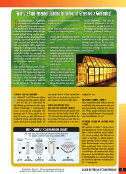
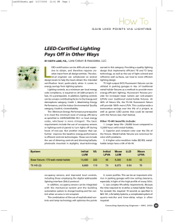


© Copyright 2026