
Document 314175
Stelladat II
User's manual
Software version: 1.32
Last revision: October 24, 2000
This PDF document has been made
exclusively for printing. Thus the links
from the online user manual have not
been transposed as Acrobat links.
SAS S.A.
Ch. de la Naz 38
CH-1052 Le Mont (Switzerland)
www.sonosax.com
Table of Contents
1. INTRODUCTION & QuickStart
Page 4
2. DESCRIPTION
Top
Front side
Left side
Right side
Rear side
Page
Page
Page
Page
Page
6
8
10
12
14
3. HARDWARE SETUP
Battery
External Power Supply
Other Power Sources
Power On / Off
Lid
Loading a cassette
Configuration
Connecting Audio Sources
Analog source
Optimal gain
Modulation
Filters
Limiter
Overload LED
Panpots
Digital source
Time Code
WordClock
RS 422
Accessory Socket
Monitoring
Headphone
Control Louspeaker
Slate Microphone
1kHz Tone Generator
Main Keyboard
Function Keys
LCD Display
Page
Page
Page
Page
Page
Page
Page
Page
Page
Page
Page
Page
Page
Page
Page
Page
Page
Page
Page
Page
Page
Page
Page
Page
Page
Page
Page
Page
Page
16
16
16
17
17
17
18
18
18
18
19
19
19
19
20
20
20
20
21
21
21
22
22
23
23
23
23
25
25
4. SOFTWARE
Joystick
ESC Key
Stelladat II's Menus
Status Screens
JOG Mode
SHUTTLE Mode
Locator
CHASE Mode
REMOTE Mode
Audio Routing
Page
Page
Page
Page
Page
Page
Page
Page
Page
Page
Page
26
26
26
26
43
45
45
46
47
47
48
2
5. APPLICATIONS
Pull-up, pull-down
Monitoring
Page 49
Page 49
Page 50
6. SPECIFICATIONS
Page 52
7. OPTIONS & ACCESSORIES
Page 54
8. MAINTENANCE
Page 56
9. TROUBLESHOOTING
Software Reset
Powering Software Reset
Error Messages
Frequently Asked Questions (FAQ)
Page
Page
Page
Page
Page
10. PROM REPLACEMENT
Page 66
Appendix A
Menu Tree
Page 73
Page 73
Appendix B
DRAWINGS & DIAGRAMS
Page 80
Page 80
57
57
57
59
64
3
1. Introduction & QuickStart
Your Stelladat II digital recorder has been designed to assure you many years of irreproachable
performances. Stelladat II's reliability is due as much to its solid mechanical engineering as to a
meticulous manual assembling of selected electronic components. The updatable software
management of the device's main elements allows you the use of sophisticated functions,
unthinkable until now on a recorder of that size, and guarantees you always access to the most
recent developments.
Stelladat II, portable DAT recorder, unique on the market offering you the choice of 2 and 4
tracks, features extremely advanced engineering and characteristics.
Stelladat II includes four mic/line inputs, all outfitted with legendary SONOSAX mic preamplifiers,
input gain control, limiters, low pass filters, pan pots and output level controls. These four inputs
can be routed towards two or four tracks, with or without panpot, depending on the application.
Stelladat II has a true 4 channels input mixer. Included is a tone generator, a slate microphone
and a control loudspeaker. To also maintain the reliability under difficult temperature or humidity
conditions, the recorder contains a tape scanner heater switching on automatically when
circumstances require it.
Stelladat II records and plays back at 44.1 kHz and 48 kHz (and at 96 kHz on option). It can also
use pull-up and pull-down sample frequencies (+0.1% and -0.1% ) to meet the requirements of
NTSC video.
While Time Code DAT machines have become notorious for their frequency instability, (Time
Code drift of 20 ppm is typical), Stelladat II is as stable as its Swiss analog predecessors (Time
Code drift < 2 PPM, typically < 1 PPM), and offers an optional High Stability (oven stabilized)
crystal providing frequency stability better that 0.1 PPM.
Unique circuit design allows Stelladat II to achieve unheard of power efficiency in a DAT
recorder. Stelladat II uses only 10 to 15 watts, depending on the configuration. The power saving
software allows you to power off the analog inputs one by one, the optical inputs and outputs and
the analog outputs. Power requirements in stand by are considerably lowered allowing many
hours of typical production from a single NP-1 battery.
Stelladat II has been designed and manufactured to meet the highest standards of reliability to
operate under very rugged conditions. If service should be required, its modular design allows
any module to be removed and replaced with one single 2 mm hex wrench.
Although Stelladat II has been particularly sturdily constructed and all precautions have been
taken to avoid any damage caused by incorrect use, we advise you to invest some of your time to
carefully read this user manual.
That being said, Stelladat II is not a complicated recorder and if you don't find the time to read
this user manual before your first recording, you most certainly will achieve to use it. Its basic
functionalities are very similar to these of other well known analog portable recorders.
Before recording
If you are in a hurry, before you go on to your first recording session with your new recorder, just
read these few fundamental, little restricting rules for an optimal and comfortable use of Stelladat
II's resources:
• Never attempt to carry any hardware modification or to take apart any module before
having studied the manual.
• Never try to touch or clean the tape scanner with any object. The 4 heads inside the
drum are very fragile and can be easily damaged. Operations on these elements can only
be executed by authorized service centers.
• To clean the heads, use a cleaning cassette (Ex.: SONY DT-10 CL or similar) and read
carefully the instructions enclosed with it. We recommend playing back the cleaning
4
cassette a few seconds only. Keep in mind that the tape scanner rotates at 2000
turns/minute.
• Avoid recording programs in different formats on the same tape (e.g 2 tracks 48 kHz
followed by 4 tracks 48 kHz). Although nothing forbids it in isolation, the transition from one
format to another requires a full switching of Stelladat II, needing a certain amount of time
and is likely to cause localization problems on the tape.
• A DAT cassette lifespan is not unlimited. Playback or recording on a worn cassette can
cause errors not only in the PCM parts (audio) but also in the subcode parts which can
lead to tape-locating problems.
•
Whenever possible, avoid activating the RS422 port when it is unused.
When you use a battery, make sure that the recorder is correctly set (Power Menu > Battery
select). This precaution allows to select the correct battery manager program controlling the
switching off of Stelladat II whenever the battery is exhausted.
Always turn Stelladat II off when replacing a battery. Preferably take the battery out when you
use the external power supply.
It is normal that the power-on needs few seconds, necessary for the initialisation of the different
functions. Three microprocessors (four with the Time Code Option), two high quality AD/DA
convertors and highly sophisticated power circuits will have to communicate while you are
recording.
If you're working with Time Code, check in the Time Code Menu that the desired frame rate is
selected.
At this point, you are ready for your first recording. If anything is not working the way you
figured - don't shout: start to read this manual.
This user's manual will be updated with each new software release, allowing you to exploit to the
utmost the possibilities of your Stelladat II.
5
2a. Description - Top
6
CASSETTE TRAY
STAND BY
POWER SWITCH
EJECT
CASSETTE EJECT KEY
ESC
ESCAPE KEY
JOYSTICK
REC / F5
RECORD KEY / FUNCTION 5
STOP / F4
STOP KEY / FUNCTION 4
PLAY / F3
PLAYBACK KEY / FUNCTION 3
FF / F2
FAST FORWARD KEY / FUNCTION 2
REW / F1
REWIND KEY / FUNCTION 1
LINK
LINK CHANNELS 3 AND 4 KEY
OVD
OVERLOAD LED FOR CHANNELS 1- 4
LINK
LINK CHANNELS 1 AND 2 KEY
LEVEL
CHANNEL LEVEL CONTROLS 1- 4
PAN
PANPOTS CHANNELS 1 - 4
80 / LIN /120
HIGH-PASS FILTERS CHANNELS 1, 2, 3, 4
GAIN
GAIN SELECTORS
12 / DYN/LIN / 48
LINE / MICROPHONE POWER SELECTOR
7
2b. Description - Front
8
LCD DISPLAY
LEFT / ST / 1-2
MAIN CONTROL CHANNELS 1-2
SLATE MICROPHONE
RIGHT / 3-4
MAIN CONTROL CHANNELS 3-4
MON
DIRECT / TAPE KEY
DISP
STATUS DISPLAY / *(LEVEL METER SWITCHING) KEY
*(FOR 4 TRACKS MODE)
PRG
BLANK SEARCH ON /OFF KEY
REWIND / INDEX SEARCH BACK KEY
FAST FORWARD / INDEX SEARCH FORWARD KEY
RECORDING / POWER ON KEY
PAUSE KEY
STOP / POWER OFF KEY
PLAYBACK KEY
9
2c. Description - Left
10
LEFT / 1 IN
ANALOG INPUT LEFT / CHANNEL 1
LEFT / 1 OUT
ANALOG OUTPUT LEFT / CHANNEL 1
RIGHT / 2 IN
ANALOG INPUT RIGHT / CHANNEL 2
RIGHT / 2 OUT
ANALOG OUTPUT RIGHT / CHANNEL 2
3 IN
ANALOG INPUT CHANNEL 3
3 OUT
ANALOG OUTPUT CHANNEL 3
4 IN
ANALOG INPUT CHANNEL 4
4 OUT
ANALOG OUTPUT CHANNEL 4
L/1, R/2, 3, 4, ST/1-2, 3-4
MONITORING SELECTOR
PHONES
HEADPHONE SOCKET
MS ON / OFF
MS MATRIX SWITCH
STEREO / MONO
MONITORING MONO / STEREO SELECTOR
HP ON / OFF
CONTROL LOUDSPEAKER SWITCH
MON LEVEL
MONITORING LEVEL CONTROL
11
2d. Description - Right
12
ACC
ACCESSORY SOCKET
WCK LOOP
WORDCLOCK LOOP SWITCH
SYNC OUT /WCK
SYNC / WORDCLOCK OUTPUT
SYNC IN / 75
SYNC / WORDCLOCK INPUT
TC
SMPTE / AES-EBU TIMECODE INPUT / OUTPUT LEMO
SOCKET
IN ST / 1-2 3-4
DIGITAL OPTICAL SPDIF STEREO INPUTS / TRACKS 12 AND TRACKS 3-4
OUT ST / 1-2 3-4
DIGITAL OPTICAL SPDIF STEREO OUTPUTS / TRACKS
1-2 AND TRACKS 3-4
TC IN
SMPTE / AES-EBU TIMECODE XLR INPUT
TC OUT
SMPTE / AES-EBU TIMECODE XLR OUTPUT
AES ST / 1-2 IN
DIGITAL AES/EBU STEREO INPUT / TRACKS 1-2
AES ST / 1-2 OUT
DIGITAL AES/EBU STEREO OUTPUT / TRACKS 1-2
AES 3-4 IN
DIGITAL AES/EBU STEREO INPUT / TRACKS 3-4
AES 3-4 OUT
DIGITAL AES/EBU STEREO OUTPUT / TRACKS 3-4
RS 422
SONY 9-PIN STANDARD RS 422 SOCKET
EXT DC INPUT
EXTERNAL DIRECT CURRENT POWER SOCKET
13
2e. Description - Rear
14
BATTERY (LITHIUM ION 14.4 V RECOMMENDED)
CONTROL LOUDSPEAKER
15
3. Hardware Setup
Inserting A Battery
Stelladat II uses NP-Format batteries. These different types are suitable:
•
•
•
NP-1B 12 V Ni-Cd and similar
NPX 13.2 V Ni-Cd and similar
NP-L40 (see note) or NP-L46 14.4 V Lithium Ion and similar (Recommended)
It's necessary to configure the device for each of these types of batteries (See Software >
Power Menu > Battery Select).
Some batteries don’t respect the NP-Standard in size and are thus too short, too long
or too thick. These batteries cannot be used on Stelladat II.
The battery holder is located on the rear side of the recorder.
Insert the battery into the holder watching over the insertion direction. To do this, first slide the
battery into the left side of the holder, the arrow on top, pointing towards the loudspeaker of the
device. Push lightly on the vertical side of the battery near the arrow and the battery will insert
correctly.
DO NOT CONNECT THE NEGATIVE POLE OF THE BATTERY TO THE
GROUND OF THE DEVICE !
Powered with a 46 Wh Lithium Ion battery, Stelladat II provides e.g. more then 3 hours of
continuous recording.
Note : By wrongly inserting the cable of the external power supply, you may cause a short
circuit between pins 1 and 4 of the external DC power socket. If an IDX NP-L40 battery is in
the holder, this causes an apparent « dead » state of the NP-L40. To correct the problem,
insert the battery once into the charger. The problem has been corrected by IDX for NP-L46.
Removing A Battery
To remove a battery, grab it between your index finger and your thumb through the side
openings of the holder and push lightly back. Then lift the battery to extract it from the holder.
Connecting The External Power Supply
The power supply provided with Stelladat II, to be connected on 100-240V 50/60Hz AC main,
delivers 12V DC. Connect the XLR-4 plug of the supply to the external DC power socket.
If the external power supply is connected while a battery is in the holder, Stelladat II
switches automatically to the external power supply. Preferably take the battery out
when you use the external power supply.
16
Connecting Other Power Sources
Stelladat II can be powered from another DC source. Here is the pin out of the external DC
power socket (XLR-4):
1
2
3
4
0V
U Batt
T Batt
8.8 V* - 18 V DC / 2.5 A
TO USE
DO NOT USE
TO USE
*)10.8 V with High Precision Oscillator Option
To keep its maximal performances, Stelladat II must use a separate power source
(avoid using one source for several appliances).
Power On
Po
Stelladat is turned on with the STAND BY key
(page 6), located on the top of the device.
Depending of the position of its use, it can also be switched on with the REC key
(page 8)
located on the front side of the recorder. The power on takes few seconds, necessary to initialize
different functions.
Power Off
Stelladat II is turned off with the STAND BY key
(page 6). The STOP key
(page 8) can
also be used for powering off. As a safety measure, switching off by this mean needs to hold the
key for at least 3 seconds.
Opening The Lid
To open the lid, pinch the locker between thumb and index finger. Closing the lid works the
same way.
Extracting The Lid
For interior or studio use the transparent lid can be extracted to facilitate access to the elements
located on the device's top side. Open the lid placing it in the upright position and pull up gently :
the hinges release from their slot. Store the lid where it cannot be scratched.
To put the lid back in place, grab one hinge with each hand, holding it upright and insert gently
the hinges into their respective slot. Push down softly until you hear a click.
17
Loading A Cassette
Press the EJECT key
(page 6). The cassette tray opens. Insert the cassette into the tray in
the direction of the arrow. Close the drawer pushing down gently until you hear a click. The
cassette is loaded.
Use professional DAT cassettes only. Don't use cassettes longer than 120' (thinner
tape).
A DAT cassette's lifespan is not unlimited. Playback or recording on a worn
cassette can cause errors not only in the PCM parts (audio) but also in the subcode
parts which can lead to tape locating problems.
Configuring Stelladat II
Stelladat II can be configured in 2-tracks or 4-tracks mode, using various sample frequencies
(Configuration Menu > Working Cfg > Working mode). Moreover, each mode offers several
routing configurations of the inputs towards the tracks. Mode and audio routing configuration is
carried out by software (Configuration Menu > Audio Routing).
Connecting Audio Sources
Stelladat II was designed to support all types of analog and digital audio signals. The selection of
audio type source, analog or digital is carried as well by software (Configuration Menu > Working
Cfg > Source select).
Analog inputs and outputs are located on the left side of the recorder. Digital inputs and outputs
are located on the right side.
Connecting an Analog Source
Before connecting a source, set the Line / Microphone Power Selector
(page 6) of the
selected input to the position corresponding to the signal to be connected. Set the selector to the
center position (DYN/LIN) for dynamic microphones or line level signals. Place the selector to the
left for microphones requiring T12 V powering. The right position is for microphones with a
phantom +48 V powering.
To avoid overload of the pre-amps, place the gain selector
Insert the XLR-3 plug into the
,
,
or
(page 6) in its 0 position.
(page 10) selected input.
18
Optimal Gain Setting
The gain selectors
(page 6) allow to set the amplification of the analog inputs of the recorder
in a range of 70 dB by steps of 14 dB. The Overload LED's
detect too hot signals for each
input. When a LED lights up, the gain has to be decreased until the LED goes out. The fine gain
setting is done with the Channels Level Controls
.
Maximal input level: + 18 dBu.
In order to save energy, the analog outputs of Stelladat II are OFF by default. To
switch them on by software, see Power Menu, > Analog Power > Outputs.
The output level of Stelladat II depends on the software selected dB scale (Setup
Menu > Display > dB scale). See Output Levels Table on page 74.
Level Setting
For this setting the Main Controls
and
(page 8) must be set into their 0 position. Adjust the
channel level control
(page 6) until the LED lights up, then turn gently back until the LED
goes out.
Modulation Setting
The modulation setting is carried out by the Main Controls and
(page 8) , depending on the
software selected audio routing (Configuration Menu > Audio routing).
In four-tracks configuration the main controls have effect on the input channels 2 by 2 (1-2 and 34). In stereo or double-stereo configuration, or for other applications, the channel level controls
can be linked 2 by 2 with the LINK switches (
and
(page 6).
Filters
Each analog input has a two-position High Pass Filter
(page 6): 80 Hz and 120 Hz. These
filters have a slope of 12 dB/octave. The LIN position of the selector sets the filters off and leaves
the signal unchanged.
Limiter
Each input module includes a limiter. These limiters can be switched on or off by software (Setup
Menu > Limiter). Their default configuration is ON.
Stelladat II's limiters, designed from the legendary limiter of the SXS portable mixer offer a large
modulation reserve. Their use allow not to hesitate to modulate hot, not for all that to risk an
overload. They're protecting the AD converter from overloads and limit the signal to -2 dBFS.
The limiters can be set OFF whenever the signal level is predictable (rehearsed recordings). For
voice, news, documentary or feature recordings they can stay constantly on. Their acting will be
absolutely inaudible by brief overmodulations.
19
Overload LED's
The Overload LED's
(page 6) light up 4 dB under the input's overload level. The input level is
measured at the preamp's output, after the filter.
Panpots
The Panpot's
(page 6) function is to distribute the incoming signal towards the tracks. Their
working depend on the selected audio routing configuration (Configuration Menu > Audio
routing). In some configurations, they're ineffective.
Connecting A Digital Source
The digital AES/EBU format is supported at the inputs and outputs of Stelladat II.
The digital inputs are located on the right side of the recorder.
The digital input sockets
(page 12) for tracks 1 and 2 and
for tracks 3 and 4 are XLR-3, as
are the digital output sockets
(tracks 1 and 2) and
(tracks 3 and 4).
The optical digital in- and outputs are usually covered by a protective plate main-tained in place
by a knurled-head screw. The sockets
are the optical inputs for tracks 1 - 2 and 3 - 4 and the
sockets
are the outputs.
In order to save energy the optical digital in- and output's default configuration is OFF. They can
be turned ON by software (Power Menu > Optical).
By simultaneous connecting of signals on both types of digital inputs, optical and
XLR, the signal connected to the optical sockets has priority.
No level setting is necessary on both types of digital inputs, thus the signal is recorded at its
nominal level.
Connecting Time Code
Stelladat II has on option an internal Time Code generator accepting all usual formats at in- or
output:
•
•
•
•
•
•
30 non-drop
30 drop
29.97 non-drop
29.97 drop
24
25
The generator is also designed to regenerate incoming Time Code (JAM SYNC function). So the
user, configuring the recorder in the Time Code Menu, can select a setting perfectly adapted for
his application.
The Time Code can be connected to two types of sockets, at user's choice. In the case of two
Time Code signals connected simultaneously to both types of input sockets, the Lemo socket
20
has priority (signal auto detection). For output, both types of sockets can be used
simultaneously.
The sockets
and
(page 12), respectively the input and output, are XLR type (SPMTE/EBU
Time Code Format). The input sensitivity of these sockets is 200 mV - 10 V pp for an impedance
< 2 kΩ diff. The output voltage is 2 V diff. nominal pp for an impedance < 250 kΩ.
The Lemo-type
socket is a combined in/output in Aaton format, fully compatible with the
Aaton standards (Time Code and ASCII). The Lemo socket is at TTL level. The input impedance
is > 10 kΩ and the output impedance < 250 kΩ.
The Time Code inputs and outputs are located on the right side of the recorder.
Connecting Digital Sync (WordClock)
Stelladat II can be synchronized with an external WordClock or video (NTSC and PAL) signal
which is to be connected on the BNC-type socket
(page 12). The recorder recognizes
automatically the type of signal used and displays it on the Status screen:
•
•
•
•
WCK 44
WCK 48
VIDEO PAL
VIDEO NTSC
Stelladat II can also act as a WordClock generator or be inserted in a sync chain, thus has
therefore an output ( ). When the output is not used, the WordClock loop switch WCK LOOP
must be set to the WCK position.
Connecting RS422
A SONY-9 pin type remote can be connected to the RS 422 socket
(page 12). This DB-9 type
socket is software activated (Configuration Menu > Remote Control > RS422). Here is the pinout of the socket:
1
2
3
4
5
6
7
8
9
Frame Ground
Transmit A
Receive B
Transmit Common
NC
Receive Common
Transmit B
Receive A
Frame Ground
It is strongly recommended to inactivate the RS 422 function when it is not used.
21
Accessory Socket
The Acc socket
(page 12) allows connecting an external parallel remote. The socket is of
type SONOSAX # 002211 (Arting or compatible). Here is the pin-out table of the socket:
1
2
3
4
5
6
7
8
9
10
11
12
13
14
15
16
17
18
19
20
MON L
MON GND
MON R
GND
GND
ACCESSORY
PRG
REW
MON
REC
ACCSDA
ACCSCL
DGND
U LED (100mA max)
+5V (100mA max)
STOP
PAUSE
FWD
PLAY
Monitoring
The monitoring selector
, page 10 (shown above) is used to select one two tracks to be
monitored with the headphones and with the control loudspeaker. The MONO / STEREO
selector
specifies the listening mode and the monitoring level control
adjusts the listening
level.
Headphones
The headphones are to be plugged into the PHONES socket
(6.25 mm stereo Jack, +15 dBu
@ 200Ω) located on the left side of the recorder. The monitoring of MS stereo with the phones is
easy thanks to an MS matrix, switched ON or OFF with the MS switch
, in the center of the
monitoring pane.
22
Control Loudspeaker
A control loudspeaker
(page 14) with a deliberately limited bandwidth is integrated on the back
side of the recorder. It's switched ON or OFF with the HP switch
(page 10), in the lower right
of the monitoring panel. It's level can be adjusted with the monitoring level control
.
The loudspeaker is switched off automatically in REC mode.
Slate Microphone
The slate microphone is useful for the user to record a take number or a commentary on tape (on
all available tracks). The microphone works only in REC mode and its activation is software
assigned (Configuration Menu > Function keys def) either to the PRG key
(page 8), and/or
to one of the Function keys F1 to F5 ( , , , , page 6). The microphone can be
programmed in solo mode (Mic mute option) or in addition to other incoming signals (Mic
option).
1 kHz Tone Generator
The generator is active in STOP and REC modes. Its level depends of the selected dB scale. On
the -12 dB and -18 dB scales its level is at the scale's zero, i.e. -12 dB FS and -18 dB FS
respectively. On the 0 dB DSP scale its level is - 9 dB FS (EBU standard). See Output levels
table on page 74. The generator's activation is software assigned (Configuration menu >
Function keys def.) either to the PRG key
(page 8), and/or to one of the Function keys F1 to
F5 ( , , , ,
page 6). The generator can be programmed in solo or in addition to other
incoming signals. Moreover, for measure or test tasks, the function keys can be set in toggle
mode.
Main Keyboard
The main command keys are located on the front side of the recorder.
Fast Forward (FF) key. The LED lights up. To stop : STOP key.
Two or more rapid keystrokes put the recorder in Index forward search mode. e.g. 6
strokes = 6 ID forward. The LED glows up. When all leds are off: the searched ID is
reached. Stelladat II's behavior depends then from the selected Mode after loc option
from the Configuration menu.
In PLAY mode: Audible search mode forward at x5 speed.
23
PAUSE key. In PLAY mode, stops the playback. The LED glows up and the PLAY
LED keeps glowing. To resume playback: PLAY key.
In REC mode, stops recording. The LED lights up and the REC LED keeps
glowing. To resume recording: REC key.
PLAY key: playback. The LED glows up. To stop playback: PAUSE or STOP key.
Works also as optional record unlock key.
In PLAY or REC mode, tape positions marker key (Locator).
Rewind (REW) key. The LED glows up. To stop rewinding: STOP key.
Two or more rapid keystrokes put the recorder in Index back search mode. e.g. 4
strokes = 4 ID back. The LED glows up. When all leds are off: the searched ID is
reached. Stelladat II's behavior depends then from the selected Mode after loc
option from the Configuration menu.
In PLAY mode: Audible search mode back at x5 speed.
Recording (REC) key. Depending of its programming (Configuration Menu >
Record key mode), single or associated with the PLAY key: starts recording. The
LED glows. To stop recording: PAUSE or STOP key.
In REC mode, a keypress records a new START ID.
In Power OFF mode: holding down the key turns the recorder on.
STOP key.
Leaves the other modes. The LED glows. The tape is engaged in the tape scanner.
A subsequent keypress disengages the tape off the tape scanner. The LED turns
off.
In Power ON and STOP mode: holding the key during 3 sec. turns the recorder off.
MON key.
In REC mode: A press on this key switches the monitoring to TAPE mode: the
recorded tape is monitored.
is displayed. A subsequent press on the key
resumes DIRECT monitoring mode: the sound before recording is monitored,
is displayed.
In STOP mode: 1 second press accesses Go to last rec function. As far as the
tape has not been ejected since, Stelladat II locates the tape at the end of the last
recording.
Pressed simultaneously with the DISP key: Display of PCM errors.
PRG key (a.k.a. User key).
In STOP or PLAY mode, a press on the key enters the BLANK SEARCH mode:
The device detects the blank unrecorded section of the tape. In PLAY mode, the
recorder stops the tape at the end of the recorded part. A subsequent press exits
the BLANK SEARCH mode.
In REC mode this key is assignable (Configuration Menu > Function keys def >
PRG key). The user has three choices: MIC MUTE, TONE MUTE or Disabled.
DISP key.
In REC, PLAY or STOP mode, repeated strokes on this key display the Status
screens: a set of useful informations about the recorder's confi-guration consultable
even while recording.
If the four-tracks module is installed: holding this key for two sec. switches meter
display mode: the four meters are drawn broader for better readability.
Pressed simultaneously with the MON key: Display of PCM errors.
24
Function Keys
These keys are located on the recorder's top.
The default function of these keys is described by their primary name. Many other functions can
be software assigned to these keys, at the needs of the user. See Software > Function keys.
LCD Display
Stelladat II is fitted with an LCD screen which, because of its transflective nature, is visible also
in high ambient lighting conditions. A backlighting, whom intensity is software set (Power Menu >
Backlight), allows reading in the darkness. The main function of the display is for checking the
record and playback levels. The type of meter (VU-meter or Peak-meter) and the dB-scale are
software set (Setup Menu > Display > dB scale).
The display allows moreover a visual check of many functions of Stelladat II: Battery power
gauge, two programmable counters, Time Code rate, source of monitoring, working mode, sync
mode, alarms, etc.
The many menu options are also displayed on the LCD screen. See Software > Menus.
25
4. Software
Stelladat II's software contains many possibilities of configuration, multiple useful settings and
several sophisticated functions, unique on a recorder of that size.
The Menu Tree is displayed on the LCD screen. The first line shows the active menu or submenu. The access to the Menu Tree is only available in STOP mode, pressing vertically on the
joystick.
Joystick
The joystick and the ESC key allow access to all the menus of the recorder. The joystick is the
main tool for navigating through the menus. It is also used in the JOG and SHUTTLE modes to
varispeed-search the tape in both directions, and from the Locator to reach four previously stored
tape locations.
ESC Key
The first function of the ESC key is to cancel the last choice while navigating in the menus.
It is also the enter and exit key for the LOCATOR Menu (in STOP mode) and allows to clear
stored tape locations in PLAY or REC mode.
Stelladat II's Menus
Stelladat II's menus can be accessed in STOP mode only. A vertical press on the joystick is all it
needs to display the MAIN MENU window. A push on the joystick to the right
accesses the
Time Code Menu. Pushing down
scrolls down to the next menu. In this way it is possible to
navigate through the menus, the sub-menus and the latter's choices. A vertical press confirms a
displayed choice. If the user decides however to maintain his previous selected choice, pressing
on the ESC key cancels. To scroll back in the Menu Tree, move the joystick to the left
or up
26
. After having confirmed a choice with a vertical press on the joystick, a subsequent press exits
the menus and resumes to STOP mode. While the menus are being displayed, the others
functions of the recorder are disabled.
Detailed Menu Description
Time Code Menu
ID Menu
Setup Menu
Configuration Menu
Power Menu
User Settings Menu
Information Screen Menu
Locator Menu
This page
Page 30
Page 31
Page 34
Page 38
Page 40
Page 41
Page 42
> Time Code Menu
This menu manages the optional Time Code module. If Stelladat II is not outfitted with it, the
Time Code menu is not displayed.
> Generator sub-menu:
> Set from external sub-menu:
By calling this function the user synchronizes the internal Time Code generator
to an external reference provided via the Aaton or the XLR TC socket. Set from
external is only a punctual setting of the internal generator and shouldn't be
confused with Input source/External below.
> Set from rec clock sub-menu:
This function sets the Time Code to the value of the internal clock.
> Set manual sub-menu:
To manually enter a start value for the Time Code generator.
> Running mode sub-menu:
There are two modes of Time Code incrementation. In the first one, Free run,
the Time Code is incremented continuously, as long as the recorder is powered
on, whereas in Record run mode, the Time Code is only incremented when
Stelladat II is in REC mode. Record run is essential to get continuous Time
Code on tape.
So that the Record run mode can work, Internal has to be selected in
the Output source sub-menu below.
27
> User bits mode sub-menu:
Defines the allocation of the user bits of the Time Code
•
•
•
•
Date
Date auto inc.
Free
Free auto inc.
The mention auto inc. means that the counter formed by the two last digits is
incremented by each new START ID writing.
> Input format and Output format sub-menus:
Allow to define the incoming and outgoing Time Code formats:
•
•
•
•
•
•
30 non-drop
30 drop
24
25
29.97 non-drop
29.97 drop
Note: The option Auto detect is not implemented yet.
> Input source sub-menu:
Allows to set the source of incoming Time Code. To select the internal generator's
Time Code, activate the Internal option.
External no jam and Ext. jam sync are two useful options when the Time Code
used is external (TC XLR or Aaton sockets) with this difference: If the external Time
Code flow is interrupted (cable disconnected, for ex.) the Time Code freezes if the
option External no jam has been selected, it gets regenerated by the internal
generator when Ext. jam sync has been chosen.
> Output source sub-menu:
Allows to set the source of outgoing Time Code, i.e. the Time Code present on the
TC output sockets and on the display. There are two choices: The Time Code
recorded on tape (Tape) or the one produced by the internal generator (Internal)
So that the Record run mode can work, Internal has to be selected in
the Output source sub-menu below.
28
> Default values sub-menu:
The options
•
•
User def. Set
User def. Recall
allow respectively to save and to recall a default user Time Code setting. The options
•
•
•
•
Film USA
Video USA
Film Europe
Video Europe
are another way to define TC format, based on the applications and taking existing
standards in account.
> Chase offset sub-menu:
The user can manually enter an offset value on this screen, to be used in Chase
mode. (Offset is the difference between an external Time Code and the Time Code
on tape for any given point to be synchronized).
29
> ID’s Menu
This menu is dedicated to the management of IDs.
> PNO sub-menu:
The option AUTO ON makes Stelladat II associate a number to every START ID
written on tape. This number equals the previous ID number +1 or is equal to 001 if
the cassette is at the BEGIN OF TAPE or if Stelladat II couldn't read the previous
START ID since the cassette was loaded. This option is ineffective if the AUTO OFF
option of the Start ID sub-menu below has been selected, because there can't be
any PNO without START ID. If the AUTO OFF option of the sub-menu PNO is
selected, no number will be associated to the START ID.
> Next PNO sub-menu:
Allows to associate a number to the next START ID to be written on tape.
> Reset PNO on eject sub-menu:
The default value of this function is ON. If ON is selected, the PNO recording counter
is reset when the cassette is ejected. If OFF, on the other hand, has been selected,
the value of the last PNO written on the ejected tape is stored. In this way, the ID
numbering can be carried on from one cassette to the other without any further
intervention of the user.
> Start ID sub-menu:
Activates (AUTO ON) or disables the automatic recording of a START ID by each
press on the REC key.
30
> Setup Menu
> Display sub-menu:
> Meter selection sub-menu:
To select level meter mode:
•
•
•
Peak meter
Peak meter max
VU-meter
> Counter # 1 and Counter # 2 sub-menus:
The two counters displayed on screen are configurable according to the needs
of the user and the options installed in the recorder. Counter #1 is the upper
counter and Counter #2 the lower one. The values assignable to the counters
are:
•
•
•
•
•
•
Absolute time
Program time (elapsed time since the last START ID)
Index time (useful option for the manufacturer only)
Timecode time
Timecode us. bits (user bits)
Delta TCext vs tape which indicates in Chase mode (Configuration Menu >
Chase Mode) the offset between Stelladat II and an external Time Code.
When Stelladat II is locked to an external Time Code, the offset value is
00:00:00:00.
> Rec date display sub-menu:
To display the date recorded on tape on the lower part of the screen, instead of
the power gauge.
> dB scale sub-menu:
To select the level meter dB scale. Each dB scale has a corresponding analog
output level and a 1 kHz tone generator level. To see these values, see the
Output Level Table, page 75.
> Limiter sub-menu:
Enables the limiter (LIMITER ON), or disables it (LIMITER OFF).
31
> Sonorous alarm sub-menu:
There are mainly two acoustic communication modes from Stelladat II towards the
user:
The message mode characterized by a single beep to inform that (for ex.) there is
no cassette in the holder even though a transport key has been pressed.
The alarm mode characterized by intermittents beeps to warn of facts of a higher
seriousness, generally of working or configuration problems of the recorder.
These acoustic warnings come together with an error message on screen, describing
the issue. In this sub-menu, the user can enable (ON) or disable ( OFF) the sonorous
alarm, without however affecting the error message display.
> Recording Mode sub-menu:
> The ASSEMBLE REC option
is used for normal audio recording. In this mode, Stelladat II records two or four
tracks as well as subcodes, i.e. related informations like Time Code and ID's.
> When the SUBCODE ONLY option
is selected, the ID status screen accessible via the DISP key changes look and
displays the subcodes modification options:
— SUB MODIFICATION —
> START ID WRITE
START ID ERASE
RENUMBER
> The START ID WRITE option
lets you write a START ID directly on tape. For this, place the cursor (>)
facing START ID WRITE and hit the REC key.
> The START ID ERASE option
lets you erase a START ID on tape. Place the tape downstream of the
START ID to be erased, place the cursor (>) facing START ID ERASE and
hit the REC key.
> Finally, the RENUMBER option
lets you renumber all the START ID's present on the tape, in increasing
order and by unity step without modifying their location. Insert a cassette in
the tray, place the cursor (>) facing RENUMBER and press the REC key: a
new screen opens where you're expected to enter, via the joystick, the
number for the first START ID of the tape. Pressing vertically on the
joystick starts the operation which can last a certain amount of time
because one single START ID's modification requires at least 9 seconds.
32
> Rec date clock sub-menu:
To set the time and date recorded in the subcode. The display format is Year |
Month | Day - HH | MM | SS.
> Output select sub-menu: (new in v. 1.32)
Allows to diversify the signal routing towards the analog outputs. See Applications >
Monitoring.
Auto option: unchanged functioning compared to the previous software versions. In
PLAY mode, the audio on the analog outputs is identical to what can be heard in the
headphones. In all other modes, the analog output of the mixer is routed towards the
analog outputs without AD / DA conversion.
Monitor option: In all modes, the audio on the analog outputs is identical to what can
be heard in the headphones.
33
> Configuration Menu
> Working cfg sub-menu:
> Working mode sub-menu:
To select the recording format:
•
•
•
•
2 tracks 44.1 kHz
2 tracks 48 kHz
2 tracks 96 kHz
4 tracks 48 kHz
> Sampling up/dwn sub-menu:
To alter the sampling frequency according to the needs of NTSC video:
•
•
•
Nominal
Down 1‰
Up 1‰
See explanatory text page 49.
> Emphasis sub-menu:
Enables (ON) or disables (OFF) the use of emphasis by recording. Tapes
recorded with emphasis will playback correctly regardless of the option selected
here (Autodetection).
> Source select sub-menu:
Let's you select the audio source type for recording:
•
•
Analog
Digital
> Reference Clock sub-menu:
Indicates Stelladat II on which clock to line up. Internal makes it derive its clock
from the internal oscillator. Digital does it take the clock from the incoming
digital signal. Lastly, External Ref orders it to take the clock from the incoming
sync signal (via BNC socket).
34
> Audio Routing sub-menu:
Audio can be software routed in eight different ways. The audio routing affects the
distribution of the four inputs towards the configuration-depending available tracks,
the action of the main controls on Stelladat II's front panel as well as the effect of the
panpots :
•
•
•
•
•
•
•
•
Mono
Stereo
Stereo link
2 tracks direct
Input 1 > L Input 2-3-4 > R
4 tracks direct
Double stereo
1-2> Stereo 3-4 > direct
For a detailed description of all available possibilities, see the Audio Routing Table
on page 47.
> Record key mode sub-menu:
RECORD mode can be launched either by a single press on the REC key or by
holding down the PLAY key and pressing the REC key. In this sub-menu the user
decides which way is more appropriate to him (Rec/Play key or Rec Key).
> Function Keys def. sub-menu:
> PRG key (in Rec mode) sub-menu:
Let's define the allocation of the PRG key in REC mode. There are three
options:
•
•
•
TONE MUTE: Activates the 1 kHz tone generator in solo-mode on all tracks.
MIC MUTE: Activates the slate microphone in solo-mode on all tracks.
Disabled: This option inactivates the key and allows thus to avoid any
accident if the key is inadvertently pressed during recording.
The selected option is displayed on the status screen, ID's STATUS pane.
35
> F1 - F5 sub-menu:
These sub-menus allow to assign one option among 14 to each of the five function
keys:
•
•
•
•
•
•
•
•
•
•
•
•
Original: The original key's function corresponding to the second menu
indication (e.g. F3 / PLAY).
Tone: In STOP or REC mode, holding down the key activates the 1 kHz tone
generator on all tracks in addition to any incoming signals.
Tone mute: In STOP or REC mode, holding down the key activates the 1 kHz
tone generator on all tracks in solo mode.
Tone toggle: In STOP or REC mode, a stroke on the key activates the 1 kHz
tone generator on all tracks in addition to any incoming signals. A subsequent
press inactivates it.
Tone mute toggle: In STOP or REC mode, a press on the key activates the 1
kHz tone generator on all tracks in solo mode. A subsequent stroke inactivates
it.
Mic: In STOP or REC mode, holding down the key activates the slate
microphone on all tracks in addition to any incoming signals.
Mic mute: In STOP or REC mode, holding down the key activates the slate
microphone on all tracks in solo mode.
Shuttle mode: In STOP or PLAY mode, pressing key enters the SHUTTLE
mode: Fast manual tape navigation is commanded by pushing the joystick.
Jog mode: In STOP or PLAY mode,pressing the key enters the JOG mode:
Fine manual tape navigation is commanded by a holding the joystick.
Locator mem 1 - 4: If tape location have been stored (See Locator Menu and
"Stelladat II's modes > Locator), the allocation of the keys to these functions
allow to access a location immediately with a single key press.
Go to last rec: This function is useful during a recording session and allows, if
the user has executed any operation as a rewind for a check monitoring, to
find the end of the previous recording in a minimal amount of time. The
function remains operational even if Stelladat II was turned off in the
meanwhile, but is inhibited as soon as the cassette is ejected. Go to last rec is
compatible with the Record run mode of the internal Time Code generator
which provides a continuous Time Code on tape. This function is also
available, without any configuration, with a 1 second press on the MON key in
STOP mode ( new v. 1.32).
TC chase ON/OFF: This function allows to assign a key to enter / exit the
CHASE mode (see "Stelladat II's modes > Chase Mode and sub-menu Chase
Mode below).
> Remote control sub-menu:
The RS422 option allows to remotely control Stelladat II with a SONY-9pin type
remote connected on the RS 422
(page 12) socket. This function activates
(RS422) or inhibits (OFF) the serial port, located on the right side of the recorder. For
more information on the possibilities of Stelladat II in remote mode, see "Stelladat II's
modes > Remote (RS422) on page 47.
It is strongly recommended to disable the RS422 function while it's not
in use.
36
> Mode after Loc. sub-menu:
This sub-menu allows to define in which mode the recorder is set after an ID or
Locator address search. The choices are:
•
•
PLAY Mode
STOP Mode
See "Stelladat II's modes > Locator on page 46.
37
> Power Menu
This menu treats of power management and allows to exploit the resources of Stelladat II in good
knowledge to save the battery's load for increased autonomy.
> Led brightness sub-menu:
The LED's associated with the transport keys can glow at HIGH or LOW intensity, at
the user's choice.
> Screen contrasts sub-menu:
To adjust the LCD screen's contrast manually via the joystick.
> Backlight sub-menu:
To select the LCD screen backlight's intensity:
•
•
•
•
OFF
LOW
MEDIUM
HIGH
> Optical sub-menu:
To activate (ON) or inhibit (OFF) the powering of the digital optical in/outputs.
> Analog Power sub-menu:
The analog inputs can be powered off separately (Input channel 1 to 4, ON/OFF)
while the four analog outputs are powered together (Outputs ON/OFF).
> Time Out sub-menu:
Opens a new page, Time out menu, which displays:
> Drum in stop mode sub-menu:
To set the time during which the tape scanner remains rotating in STOP mode:
•
•
30 sec
15 min
38
> High Osc sub-menu:
This function only appears in the sub-menu if Stelladat II has an optional High
Precision Oscillator. The function allows to power the oscillator during an
amount of time defined by the user after having turned the recorder off, in order
to maintain the internal Time Code Generator's alignment with an external
reference, e.g. common to several equipment.
•
•
•
•
•
•
•
•
Off immediately
15 min
30 min
1 hour
2 hours
3 hours
4 hours
5 hours
When Stelladat II is off and the oscillator is powered, the STAND BY LED,
located on the top side of the recorder, is blinking.
39
> User Settings Menu
Stelladat II can store four different User Settings for specific applications. This function is also
useful if several people work with the same recorder, saving to everyone the trouble of manually
enter the various parameters. Called by default User Setting 1 to 4, these settings can be
configured, named, loaded and edited anytime and include Stelladat II's following parameters:
•
•
•
•
•
•
•
•
Time Code (running mode - Free run or Record run - sources and in- and output formats)
Battery type
Display configuration (counters, level meters, date)
Audio routing
Recording mode (number of tracks, sampling frequency, assemble or subcodes).
Audio source (analog or digital).
Reference clock (internal, external or digital).
Powering state of the analog in- and outputs and of the digital optical in/output.
As well as several options:
•
•
•
•
•
•
•
Limiter on or off
Emphasis
Key combination to start recording (REC key only or REC and PLAY key simultaneously)
Automatic recording of START ID and END ID
Mode after loc
Rotating time of the tape scanner in STOP mode
Activation of the RS422 serial port
To save a configuration: Place the cursor > facing the User Setting number under which the
parameters are to be stored, select Store and confirm by pressing on the joystick.
To load an existing configuration, the procedure is identical but Recall is to be selected instead
of Store.
To name a User Setting after having saved it with Store, select the Name function: a new
screen appears which allows to compose a name with alphanumeric characters. The moves of
the joystick
allow to navigate through the characters, a vertical pressure selects one. The ESC key cancels
the procedure if the field is empty or erases the last entered character. A name can include 14
characters and is validated as soon as the 14th character has been entered. If the name
includes less than 14 characters, fill up the field with spaces.
40
> Information Screen Menu
> General Information sub-menu:
This screen displays several informations useful for the user or for SONOSAX or his
authorized service centers:
Software version
: Main software version
Heads
: Hours of use of the heads
Mst serial #
: Serial # of the device
Trsp serial #
: Serial # of the transport assembly
Quartz type
: Oscillator type (standard or High Precision)
Screen type
: LCD screen type (standard or High Contrast)
Pic version
: Auxilliary software version
> Power Information sub-menu:
This screen displays various electrical values present in the device, useful for the
user or for SONOSAX or his authorized service centers. All what you have to do is
multiply the voltage by the indicated value.
e.g. U +V : 34 * 0.33 V = 11.22 V
U +V
Voltage of the safeguard battery (acceptable values: 3.1V 2.9V)
Analog power voltage (normal value: 11V)
U DV
Digital voltage (normal value: 5V)
I Brut
Current (normal value 1A /12V)
U Brut
Powering voltage (normal value 9V - 18V)
Ulith.
41
> Locator Menu
To enter the Locator Menu, press [ESC] in STOP mode.
The Locator allows the user to store four tape locations (Time Code or Abs Time
addresses) and to access them automatically and rapidly later on.
The LCD displays indicates the still available Locator memory registers, maximal 4 (4Mk).
In PLAY or REC mode a push on the PLAY key stores the current tape location's address
in the next available memory register. To recall a stored location, enter the Locator menu
(press [ESC] in STOP mode) and select the desired register with the joystick:
A vertical pressure on the joystick starts instantly the search of the selected location on
tape.
Another, faster way to access Locator stored locations is to assign one or several memory
registers to the function keys. A push on the corresponding key searches then the stored
location.
(See also Mode after Loc. sub-menu on page 37)
Please note that the four Locator memory registers are cleared as soon as the cassette is
ejected.
The two sub-menus Loc to Abstime and Loc to TCtime allow to manually enter an
address. A vertical pressure on the joystick starts the search of the desired location on
tape. In STOP mode, pressing the ESC key exits the Locator menu. In PLAY or REC
mode, pressing this key clears the memory registers and makes them available for new
locations.
42
Status Screens
These screens can be accessed in REC, PLAY and STOP modes pressing the DISP key and
allows to verify rapidly the main selected configuration options, even while recording.
The first two screens are dedicated to the configuration of the recorder:
Cfg
Rout
Freq
Sync
Emph
Record
Lim
Tape
Copy
Blank
Remote
Temp
--- STATUS (1) --: Track system selected (TWO TRACKS or FOUR TRACKS)
: Selected audio routing (e.g. STEREO)
: Sample frequency selected (44.1 kHz, 48 kHz or 96 kHz).
+ or - point out pulling up or down. INT indicates the recorder's configuration.
TAPE indicates the value read in playback.
: Selected sync source (INTERNAL, EXTERNAL, VIDEO PAL, VIDEO NTSC or
WCLK)
: Emphasis enabled (ON) or disabled (OFF). INT stays for the recorder's
configuration. TAPE indicates the value read in playback.
: Recording mode: ASSEMBLE (audio) or SUBCODES ONLY
--- STATUS (2) --: Limiter enabled (ON) or disabled (OFF)
: Cassette unlocked (WRITEABLE) or locked (WRITE PROT)
NO TAPE: No cassette in the tray.
: Copy (ALLOWED) or (PROHIBITED)
NO TAPE: No cassette in the tray.
: BLANK SEARCH function enabled (ON) or not (OFF).
: Remote mode activated (RS422) or not (OFF).
: Internal temperature of the recorder in Celsius (e.g. + 36 deg [C]).
The third status screen's first panel is dedicated to the ID's. The second panel handles of
powering of the inputs and outputs:
User prog
AUTO PNO
AUTO START
Ins
Outs
--- ID’s STATUS --: Function allocated to the PRG key in REC mode:
TONE MUTE or MIC MUTE
: Automatic ID number by each press of the REC key:
(ON or OFF)
: Automatic START ID by each press of the REC key:
(ON or OFF)
--- POWER STATUS --e.g. means "analog inputs 1 and 2 powered, analog inputs
3 and 4 not powered"
: ON or OFF shows the powering
Opt: ON or OFF: powering state of
state of the analog outputs
the digital optical in/outputs
:
43
The fourth screen is dedicated to Time Code configuration:
In
Out
Gen
Ubits
C.mode
Offset
--- TC STATUS 03.01 --- (Time Code software version)
Incoming Time Code format (30d, 30, 29d, 29, 25 or 24) and source (Int or Ext)
Outgoing Time Code format (30d, 30, 29d, 29, 25 or 24) and source (Int or Ext)
Running mode of the TC generator (Record run or Free run)
Content of the TC user bits (Date, Date auto inc, Free or Free auto inc)
Shows the Chase mode option selected (Mute chase, Soft chase or Hard
Chase)
: Indicates the Chase mode offset value entered. e.g. 01:30:00:00
:
:
:
:
:
44
Stelladat II’s Modes
Stelladat II, besides the classical modes of every DAT recorder, offers to the user 5 particular
modes allowing many ways of additional applications. These tools improve greatly the comfort of
use and increase the productivity:
JOG Mode
This mode allows fine manual navigation on tape by means of the joystick, the search of a
precise spot (e.g. the start of a take, a particular dialog line or the beginning of a musical
phrase).
To access this mode, assign Jog mode (Configuration Menu > Function keys def.) to a
function key.
In STOP or PLAY mode, pressing on the previously assigned key enters the JOG mode: Tape
navigation is controlled by holding the joystick. A steady press on the right
activates forward
playback at nominal speed. Pushing the joystick halfway to the top switches to the 2x speed,
halfway to the bottom the 3x speed. When the joystick reaches the upper
or lower
position
or when it's released, playback stops.Holding the stick to the left
activates reverse playback
in the same way.
A press on the STOP key exits the JOG mode.
SHUTTLE Mode
This mode permits fast manual navigation in both directions on tape by means of the joystick. It's
useful to search a musical passage, one take among others, a particular atmosphere. The
advantage of being able to change speed or direction almost instantly makes it a very flexible
tool.
To access this mode, assign Shuttle mode (Configuration Menu > Function keys def.) to a
function key.
In STOP or PLAY mode, pressing on the previously assigned key enters the SHUTTLE mode:
Tape navigation is controlled by the joystick. A stroke on the joystick to the right
activates
forward playback at nominal speed. Each subsequent push on the joystick in the same direction
increases the speed according the series 2x, 3x, 5x, 9x, 16x. Each push in the reverse direction
reduces the speed until stop, and then activates reverse playback according the same series. In
any speed, a vertical press on the stick stops playback. The mode (SHT), the playback direction
and the speed are displayed.
A press on the STOP key exits the SHUTTLE mode.
45
Locator
This device is not strictly speaking a mode. It allows to store four tape locations and to retrieve
them automatically and rapidly. It permits also to reach any Time Code or Absolute time address
on tape in a flash.
The LCD display indicates the number of still available memory registers, maximal 4 (Mk4). In
PLAY or in REC mode a press on the PLAY key stores the current tape location's address in the
next available memory register. To recall a stored location, enter the Locator menu (press [ESC]
in STOP mode) and select the desired register with the joystick . A vertical press on the
joystick starts instantly the search on tape of the selected location.
Another, faster way to access Locator stored locations is to assign one or several memory
registers to the function keys. A press on the corresponding key searches then the stored
location.
(See also Mode after Loc. sub-menu).
Please note that the four Locator memory registers are cleared as soon as the cassette is
ejected.
The two sub-menus Loc to Abstime and Loc to TCtime allow to enter an address manually. A
vertical pressure on the joystick starts the search of the desired location on tape.
In STOP mode, pushing the ESC key exits the Locator menu. In PLAY or REC mode, pressing
this key clears the memory registers and makes them available for new locations.
Chase Mode
This mode allows to synchronize Stelladat II to an external Time Code originated from another
Time Code outfitted DAT recorder (Stelladat or else), from a VTR, from a digital video or audio
workstation or from any other Time Code output enabled equipment. An offset can be entered by
the user if the external Time Code and the one on the tape of Stelladat II are different for any
given point.
The Chase mode works only in PLAY mode, it is, for obvious reasons, impossible to record in
this mode.
To access the mode, assign TC chase ON/OFF (Configuration Menu > Function keys def.) to
one of the five a function keys.
In STOP mode, a press on the beforehand assigned key enters the Chase mode, a subsequent
press exits it. If Stelladat II receives an external Time Code, it attempts immediately to find it and
to synchronize to it. This message appears on the LCD display, indicating in which direction and
at which speed de recorder searches the corresponding Time Code on tape:
e.g. CHS: >16 or CHS: < 5
As soon as Stelladat II has encountered the corresponding Time Code, it locks to it and displays:
CHS: > 1LCK
If no Time Code is present at any Time Code input Stelladat II stops and this message is
displayed:
CHS: STP (TC EXT IS MISSING)
46
If the external Time Code is smaller as the Time Code at Stelladat II's tape start, the recorder
exits the Chase mode resuming the STOP mode and displays:
START OF TAPE
If the external Time Code is greater as the Time Code at Stelladat II's tape end, the recorder
exits the Chase mode resuming the STOP mode and displays:
END OF TAPE
The offset, i.e. the value of the difference between both TIme Codes for any given point of the
tape to be synchronized, can be entered manually with the Chase offset option of the Time Code
menu.
One of the counters option (Setup Menu > Display > Counter # 1 and Counter # 2 sub-menu)
allows to display DeltaTCext vs tape on one of the counters. The displayed value indicates the
current difference between external the Time Code and the playback Time Code. When Stelladat
II has locked in Chase mode, this value is 00:00:00:00.
Three options of the Configuration Menu allow to modify the behaviour of the recorder in Chase
mode:
The Mute chase option mutes the audio while Stelladat II is searching a Time Code to
synchronize to it. The Soft chase option dims the audio down 12 dB.
The Hard chase option is useful when the external Time Code and/or the code on the tape itself
are not steady. If it's selected, as soon as Stelladat II in CHASE mode could lock without any
doubt to the external Time Code, it switches driftless to PLAY mode.
Remote Mode
This option allows to remotely control Stelladat II wit a SONY-9pin standard remote connected
on the RS 422 socket
(Page 12). It is thus possible to remote Stelladat II from a video editor,
from a digital video or audio workstation, from a multi-track recorder or any other device
delivering a command signal at the SONY-9pin standard.
All the playback functions of this standard are recognized by Stelladat II, including the cassette's
ejection. The recording functions are not implemented yet.
To access this feature, select the option RS422 in the Configuration Menu > Remote Control.
The *** REMOTE *** message is displayed.
It is necessary to disable the RS422 function when it is not in use.
47
Stelladat II - Audio routing configurations
2 Tracks mode
MONO
4 Tracks mode
TRACKS
1
2
Input 1
Input 2
Input 3
X
X
X
X
X
X
Input 1
Input 2
Input 3
Input 4
LEFT / ST / 1-2
X
X
X
X
Input 4
LEFT / ST / 1-2
RIGHT / 3-4
Input 1
Input 2
Input 3
P
P
P
P
Input 4
P
P
Input 4
LEFT / ST / 1-2
RIGHT / 3-4
X
X
LEFT / ST / 1-2
RIGHT / 3-4
STEREO Link
TRACKS
1
2
Input 3
Input 4
LEFT / ST / 1-2
P
P
X
P
P
X
Input 3
Input 4
LEFT / ST / 1-2
RIGHT / 3-4
RIGHT / 3-4
TRACKS
1 2 3 4
P P
P P
P P
P P
X X
X X
TRACKS
1 2 3 4
P
P
TRACKS
1
2
X
X
X
Software configured
Default configuration
X
X = connected
Empty = not connected
P = connected through panpot.
X
X
TRACKS
1
X
2
X
X
X
X
X
Improvements may cause change of
features and specifications without notice.
SAS SA
Version: September 24 1998 JS
P
P
X
RIGHT / 3-4
Input 2
Input 3
Input 1
Input 2
Input 3
Input 4
LEFT / ST / 1-2
X X
1-2 > STEREO
3-4 > direct
Input 1
Input 2
Input 1 > Left
Input 2-3-4 > Right
X
X X
Input 2
Input 3
P
P
Input 4
LEFT / ST / 1-2
RIGHT / 3-4
X
Input 1
P
P
Input 1
X
Double STEREO
Input 1
Input 2
Two tracks Direct
X
RIGHT / 3-4
TRACKS
1
2
P
P
STEREO
TRACKS
1 2 3 4
Four Tracks direct
X
X
X
5. Applications
Pull up, pull down
A few words of explanation about the Sampling up/down function of the Configuration menu:
The NTSC video standard is used in North America, in several countries of South America, in
Japan and in many other countries. For historical and technical reasons the frame rate of this
system, which was originally 30 frames per second became 29.97 Fr/Sec with the introduction of
color television.
Film runs in the whole world at the speed of 24 Fr/Sec through film cameras. It is projected at
the same speed in theaters. Films are transferred on video for television or for editing on
systems using video pictures. In NTSC countries, the machine used for this transfer, the
telecinema, runs at 23.976 Fr/Sec. That is 0,1% (or 1‰) slower. To remain in sync with the
picture, the sound must also be slowed down by 1‰. This slight slowing down is applied since
long ago on analog sound and works with no other problem than an almost imperceptible slightly
lower pitch.
But in the digital sound world, things are different. One could playback the recordings with a 1Ω
lower sampling frequency, of course, which has the same effect as slowing down an analog
tape, but most of the digital recorders aren't able to do this. And the AES/EBU standard, which
benefits worldwide recognition, defines that the sampling frequency is 48 KHz (or 44.1 KHz).
Well, if a standard exist, let's respect it!
The solution is quiet simple: All that is necessary is to use, during the recording, a sampling
frequency 1‰ higher (48.048 KHz instead of 48.00 KHz) and so a tape played back for the
telecinema at the AES/EBU standard 48 KHz will run 1‰ slower, at the same speed as the
picture and thus will be in sync with it. Moreover, this solution avoids a sample frequency
conversion, always harmful to the sound quality.
Stelladat II's Sampling up/down option allows exactly to face this problem, in different ways:
Selecting the option Up 1‰, the user has at his disposal a 1‰ higher sampling frequency, thus
48.048 Khz. If the tape is recorded at 44.1 KHz, Up 1 ‰ provides a sampling frequency of
44'144 Hz.
Selecting the Down 1‰ option, Stelladat II can be used to playback tapes recorded at 48 Khz
on other recorders, for a telecinema or a digital video or audio workstation.
What happens with Time Code? If the user selected 30 non drop code at 48.048 KHz, this code
will become 29.97 non drop code if the tape is played back at the standard sampling frequency
of 48 KHz.
Synchronous playbacks for music videos ask the opposite problem and are generally recorded
with a 44.1 KHz sampling frequency with 29.97 (drop or non-drop) Time Code. With Stelladat II,
no special or different recording is necessary: it's enough to playback the music tape on set with
the Up 1‰ option selected, this provides the needed 1‰ fast playback with the 30 necessary
code. No one, other than the playback mixer has to do anything special and he is, after all, the
"specialist" anyway!
(After Manfred N Klemme)
49
Monitoring
Since Stelladat II's launching until the software version 1.31, the audio available at the recorder's
four analog outputs was:
•
The recorded signal on tape in PLAY mode.
•
The mixer's output signal in all other modes ( in particular in REC mode).
Since the software version 1.32 a new option, Output select (Setup Menu > Output select)
allows to dispatch the signal toward the analog output diversifying the audio routing. A judicious
use of this options needs however the principles of audio dispatching in the recorder to be well
understood:
The simplified audio block diagram above shows this dispatching emphasizing the three
electronic switches having an effect on it:
•
Switch 1: Source select (Configuration Menu > Working configuration > Source select)
allows the user to select the audio signal type to be recorded, Analog or Digital. In the
schematics above, the analog source was selected.
•
Switch 2: Gives the choice to send to the analog-digital converter either the digitized audio
intended for the DSP (digitized output of the mixer or incoming signal from the digital inputs)
or the audio played back on tape. This switch is associated to the MON key (Tape/Direct)
located on front of the recorder. On the diagram, the switch is placed in Direct position.
Notice that the monitoring is always fed by the digital-analog converter (DAC). So, when
recording an analog source, the "direct" sound heard in the headphones is the mixer's
output converted twice (ADC then DAC).
•
Switch 3: Routes towards the analog outputs either the unconverted mixer's output, or the
DAC's output. In the 1.31 and previous software versions, this switch is in the lower position
(DAC) in PLAY mode and in the upper position in all other modes.
50
The Output select (Setup Menu >
software version, offers two choices:
Output select ) function, introduced from the 1.32
•
Auto: Unchanged working compared to the previous software versions.
•
Monitor: The switch 3 is in lower position in the REC and STOP modes and thus the
sound available at the analogic outputs is identical to what can be heard in the
headphones or in the control loudspeaker.
Note:
When the Monitor option is activated, the usual display is replaced by MTAPE or MDIRECT
respectively, to remind the user of a different routing towards the analog outputs.
Simultaneous Monitoring of Four Tracks
The headphones don't allow to monitor simultaneously more than two tracks. To hear more
tracks:
•
Connect the analog outputs to an external mixer.
•
Select the Analog option of Source select (Configuration Menu > Working Cfg > Source
select > Analog).
•
Power on the analog outputs (Power Menu > Analog Power > Outputs > ON).
•
Select the Monitor option of the Output select function (Setup Menu > Output select >
Monitor).
At this point the four analog inputs of Stelladat II are dispatched towards the external mixer.
Stelladat II, High Quality Four Tracks DA Converter
The Output Select function makes possible to use Stelladat II as high quality occasional digital to
analog converter. To do this, proceed as follows:
•
Connect a digital AES/EBU format source to Stelladat's XLR or optical digital inputs (If both
types of sockets are used, the signal present on the optical sockets has priority).
•
If the digital optical sockets are to be used, think to power them on (Power Menu > Optical >
ON).
•
Select the Digital option of Source select (Configuration Menu > Working Cfg > Source
select > Digital).
•
Power the analog outputs (Power Menu > Analog Power > Outputs > ON).
•
Select the Monitor option of the Output select function (Setup Menu > Output select >
Monitor).
At this stage, the available audio at the four analog outputs is the incoming converted digital
sound.
51
6. Specifications
TRANSPORT
Track Format
Head
Tape Speeds
Fast Wind Time
Shuttle Speeds
Jog Speeds
Play Start Time
Conforms to DAT Standard
Rotary, 4 Heads
Normal Speed Mode: 8.15 mm/s
Double Speed Mode: 16.3 mm/s
Max. 60 sec. with 120 minutes tape
1x, 2x, 3x, 5x, 9x, 16x
1x, 2x, 3x
Tape loaded: 1 sec.
Tape unloaded: 2.5 sec.
ELECTRONICS
Frequency Response
Dynamic Range
Signal to Noise Ratio
THD
Crosstalk
Samplig Frequencies
Tape Configurations
Emphasis
Phase Difference Between
Channels
Signal Delay Time
Level Meter
10 Hz - 21 kHz ± 0.3 dB (44.1 / 48 kHz)
10 Hz - 42 kHz ± 0.3 dB (96 kHz)
> 90 dB
> 90 dB
< 0.01% (-10 dBFS, 1 kHz)
> 100 dB (at 1 kHz)
44.1 kHz, 48 kHz, 96 kHz
Up / Down 1‰ supported
2 tracks, 4 tracks
50 µs/15 µs
< 10° (20 kHz)
~ 100 ms (read after write)
Peak and VU meters
TIME CODE (optional)
Time Code Reader
Time Code Generator
Connectors
24, 25, 29.97D, 29.97ND, 30D, 30ND frame rates supported
24, 25, 29.97D, 29.97ND, 30D, 30ND frame rates supported
JAM Sync function
REC RUN function
ASCII Communication Supported
XLR3-31 Active Balanced (transformerless), 4kΩ (INPUT)
XLR3-32 Transformer Balanced, 200 Ω (OUTPUT)
5p. LEMO (IN / OUT / ASCII TTL)
MIXER
Configuration
Phantom Power
Low Cut Filter
Panpots
Input Gain
Level Pots
Limiter
4 Channels
T12, 48V
80 Hz (12 dB/oct.), 120 Hz (12 dB/oct.)
YES
0 - 70 dB
Linkeable 2 by 2
ON/OFF selectable, activated 2 dBFS before clip
52
INTERFACE IN/OUT
ANALOG AUDIO
Inputs
Outputs
Phones
DIGITAL AUDIO
Inputs
Outputs
Mode:
Transformerless Active Balanced
6 kΩ
Impedance:
Connector:
XLR3-32
SRL Level:
+ 6 dBu
Max. Level:
+ 18 dBu
Mode:
Transformerless Active Balanced
Impedance:
Max. 50Ω
Connector:
XLR3-31
SRL Level:
+ 4 dBu / + 6 dBu
Max. Level:
+ 26 dBu
6 mm Stereo Phone Jack
(Load Impedance Min. 50Ω)
Format:
Connectors:
Format:
Connectors:
WORD / EXT SYNC SIGNAL
Input
Format:
Output
VIDEO SYNC SIGNAL
Input
AES/EBU
XLR3-31 (110 Ω) & Optical
AES/EBU
XLR3-32 (110 Ω) & Optical
Impedance:
Connector:
Standard Selection of Square Wave Rising or
Falling Edge (TTL Compatible)
75 Ω
BNC
Standard Selection of Square Wave Rising or
Falling Edge (TTL Compatible)
75 Ω
BNC
Format:
Level:
Impedance:
Connector:
NTSC/PAL/SECAM
0.3 - 4.0 V p-p
75 Ω
BNC
Impedance:
Connector:
Format:
SERIAL I/O, PARALLEL I/O
RS-422
Format:
Connector:
Sonosax Acc.
Format:
Connector:
Serial
D-SUB 9p. (female)
Specific
# 002211 (Arting or compatible)
GENERAL SPECIFICATIONS
Dimensions (W x H x D):
Weight:
Power Requirements:
Battery
Power Consumption:
Operating Conditions:
Storage Conditions:
280 mm x 80 mm x 216 mm
3.6 kg (Battery excluded)
AC 100-240 V, 50/60 Hz (External Power Supply)
DC 11 - 18 V (DC Direct Feed)
NP-1B 12 V NiCd /NPX 13.2 V NiCd / NP-L46 14.4 V Li-Ion
~ 15 W (depending on configuration)
n.a.
Refer to as above
53
7. Options & Accessories
Stelladat II’s Options
Stelladat II offers several options allowing either to improve its performances or to respond
particularly to an application wished by the user. All options ca be installed afterwards, together
or at once by SONOSAX or its authorized service centers.
Time Code Option
The Time Code option is essential for for film or TV intended sound recordings, but also very
useful in other fields, in particular if editing on a DAW is considered or a a precise locating on
tape is necessary. Time Code provides a mean to identify uniquely every frame on a tape, i.e.
every 25ieth or 30ieth of a second (depending of the standard used). It consists of a time
marking on tape allowing later access in a highly precise and fast way any to spot of the
recording. It's unavoidable every time a sound recording must keep track of the precise instant it
was made or when the recorded audio must run synchronous with a picture on whatever
medium.
The Locator, Chase and Remote modes are all based on Time Code.
Stelladat II's Time Code meets the worldwide recognized AES/EBU international standard.
High Precision Oscillator Option
Oven stabilized crystal. Frequency stability better that 0.1 PPM.
54
Stelladat II's Accessories
Several useful accessories are available by SONOSAX or its authorized service centers.
SXS Remote
Case
A Porta-Brace® case for Stelladat II is available exclusively from SONOSAX or its
distributors. The case allows operating the recorder comfortably on the shoulder and
provides easy access to all controls and connections of the device. A battery, in particular,
can be exchanged rapidly without extracting Stelladat II from the case. The latter, moreover,
offers a good protection against shocks, dust, sand and humidity and allows, thank to the
flexible clear vinyl windows to use the recorder even in hostile environment (rain, snow,
blizzard, etc.). The second part of the case includes 2 compartments to help organize the
most essential accessories. It holds spare cassettes, batteries, wireless microphones, and
other small items.
55
8. Maintenance
Head Cleaning
To clean the tape scanner heads, SONOSAX recommends to use a head cleaning cassette (e.g.
SONY DT-10CLD or similar). Read carefully the instructions enclosed with the cassette. We
recommend to play it back few seconds only. Keep in mind that the tape scanner rotates with
2000 turns per minute !
Replacing The Heads
The Information Screen Menu displays the number of hours of use of the heads. After 1500
hours of use the heads are considered to be worn and should be replaced. This delicate
operation can only be executed by SONOSAX ot its authorized service centers.
56
9. Troubleshooting
Dear user,
in spite of the care we took designing and manufacturing your recorder, certain problems can
appear at least.
We indicate you here two procedure allowing to, to our knowledge, to put right nearly all break
downs.
In the case where you should contact us, give us absolutely the serial number of your recorder,
the installed software version number and the version number of the time code software if it is
present. We dispose of an up-to-date data base including the hardware configuration of the
manufactured equipment, and these informations can help saving time. You can easily find them
on your recorder.
Software Reset
If your Stelladat II shows any sign of malfunctioning, carry out a software reset. You'll resume to
the default configuration corresponding to the installed software version.
To reset:
press simultaneously [ESC], [MON] and the joystick
(down).
A reset clears your own configuration and your User Settings!
Powering Software Reset
If you can't turn on your Stelladat II at all, carry out the following operations in order :
If you aren't sure that you can execute them out with the necessary precision,
contact your distributor or SONOSAX.
•
Disconnect the external power supply.
•
Remove the battery from its holder.
•
Open the bottom plate of Stelladat II: Using a 2 mm hex wrench, unscrew the four feet and
the two screws.
•
WARNING: An electrostatic discharge can destroy some electronic circuits. Avoid touching
the circuits, and before the next stage, touch the chassis of Stelladat II so as to discharge
yourself.
•
Carefully remove the 4 track board # 072101, by pulling it upwards.
57
•
With tweezers or a small piece of wire, make a short circuit for one second on the JP7 (PIC
RESET) point, according to the PIC RESET DIAGRAM in Appendix B.
•
Plug in the 4 track board # 072101 back again, checking carefully that the contacts are well
inserted.
•
Close the bottom plate of Stelladat II, screwing back the 2 screws and the 4 feet.
•
Reconnect the external power supply.
•
Turn on Stelladat II and check that it starts up correctly.
If you persist to note any anomalies, don't try anything else but contact
your local dealer or SONOSAX.
58
Error Messages
Full list of error messages:
•
•
Alarm type: This kind of message must be acknowledged by the user pressing any key
before any other command.
Message type: This type of message hasn't to be acknowledged. It's cleared as soon as the
problem which originated it is resolved.
Note: Don't take in account the messages which may appear in the first seconds after a reset.
Message displayed
Type
Meaning
AUDIO ROUTING ERROR
Alarm
Switching from a two tracks confi-guration
to four tracks or inversely, the previously
selected audio rou-ting is invalidated and
replaced by the default option, i.e. STEREO
in two tracks and FOUR TRACKS DIRECT
in four tracks.
Acknowledge the alarm and change the
audio routing if needed.
BAD EXT FREQ
Inactive message
BAD SYNC CHOICE
Message
There is an incompatibility between
Stelladat II's configuration at 96 kHz and an
external sync refe-rence at 44.1 kHz
(AES/EBU or wordclock).
Change Stelladat II's configuration.
BAT LO
Message
The battery has reached its minimal charge
level: replace it without delay
BATT NOT SELECTED
Message
If the recorder is powered with a battery its
recommended for a longer lasting of the
battery itself to inform Stelladat II of the
type of battery used, so that it can choose
the best adapted power mana-ging
program.
BLANK DETECTED
Alarm
This alarm informs that the tape section
after the current location is not format-ted.
(In BLANK SEARCH ON only)
DOWN 1
Alarm
By Stelladat II's power on only. Reminds
that the sampling frequency is altered
according to the needs of NTSC video.
SELECTED
END OF RECORD
Inactive message
END OF TAPE
Message
Self-explanatory.
EXTERN DC TOO HIGH
Message
The external powering voltage is higher
than the maximal allowed value.
EXT LO
Message
The external powering voltage is lower than
59
the minimal allowed value.
HIGH ERROR RATE
Message
In PLAY and REC modes this message
appears when the error rate threatens the
sound quality. When starting playback, this
message may appear briefly if the
cassette's format is different of Stelladat II's
configuration (e.g. tape recorded at 96 kHz
on Stelladat II set at 44.1 kHz). In this case
in particular, this message is not to be take
in account. If the display persists, it can
mean that the cassette is damaged or that
Stelladat II requires some maintenance
(cleaning cassette).
HI OSC TIME ELAPSED
Alarm
For recorders outfitted with the High
Precision Oscillator only:
By Stelladat II's power on only. This alarm
warns that the oscillator's power-ing time
has been exceeded and thus that it may be
necessary to realign the time code to the
external reference generator.
HI OSC WAS OFF
Alarm
For recorders outfitted with the High
Precision Oscillator only:
Warns that the oscillator has not been
powered after Stelladat II's powering off.
LOW TEMP! HEATER ON
Message
The tape scanner heater switches automatically on if Stelladat II's internal
temperature is lower than 10°C.
MACHINE TOO HOT
Inactive message
MOISTURE! HEATER ON
Message
The transport assembly is outfitted with a
humidity detector. Conden-sation can arise
e.g. in warm countries when exiting an airconditioned building. The tape scanner
heater is switched on automatically.
NO REC IN SUB ONLY
Message
Recording is not possible in SUBCODE
ONLY
mode.
Set the recording mode to ASSEMBLE
REC.
NO SAMPLING UP/DWN
Alarm
If Stelladat II is configured for pull up / pull
down and that it's fed by an external sync
reference that doesn't require alte-ring of
the sam-ple frequency (e.g. PAL signal),
the recorder restores automati-cally the
sampling frequency to its nominal value and
informs its user by this alarm.
NO SYNC FOR REC
This alarm appears only in RECORD RUN
timecode mode and warns the user that the
last punch in couldn't be executed. The
recorder resumes then STOP mode.
60
NO TAPE INSERTED
Message
Appears when the user presses a transport
key while the cassette tray is empty.
PIC TRANS ERROR
Message
Informs of a communication error between
the main processor (Master) and an
auxillirary processor (PIC). The concerned
command is transmitted again to the
auxilliarry processor for processing. If this
message doesn't persist don't take any
particular measure.
PAUSE ENDED
Message
When Stelladat II is in PLAY/PAUSE mode,
an internal counter makes sure that the
tape scanner doesn't rotate indefinitely,
which is harmful for the tape on the long
run. After 1 min., Stelladat goes
automatically in STOP mode and displays
this message.
READY!
Message
This message informs the user that
Stelladat II just finished the task it was
executing (e.g. Go to last rec).
RS422 ERROR TIME OUT
Message
Command reception error on the RS422
port.
RS422 REPLY TIME OUT
Message
Data transmission error on the RS422 port.
START OF TAPE
Message
Self-explanatory.
TAPE ERROR
Alarm
Transport error: the two reels are blocked
and the tape doesn't run any more. Eject
the cassette and verify.
TAPE JAM
Alarm
Transport error: one reel is blocked. Eject
the cassette and verify.
TAPE WRITE PROTECT
Message
Appears by an attempt to record on a write
protected cassette.
TC AATON COM ERROR
Message
For recorders outfitted with the Time Code
module only:
Problem or time-out encountered while
communicating with an external Aaton Time
Code device.
TC DISPATCH ERROR
Alarm
TC EXT IS MISSING
Message
For recorders outfitted with the Time Code
module only:
Time Code CPU error.*
For recorders outfitted with the Time Code
module only:
The external Time Code is missing (in
CHASE mode in particular). Verify
connections.
TC EXT RAM ERROR
Alarm
For recorders outfitted with the Time Code
module only:
Time Code CPU error.*
61
TC FUNC NOT EXEC
Alarm
For recorders outfitted with the Time Code
module only:
Time Code CPU error. *
TC HSI ERROR
Alarm
For recorders outfitted with the Time Code
module only:
Time Code CPU error. *
TC INT RAM ERROR
Alarm
For recorders outfitted with the Time Code
module only:
Time Code CPU error. *
TC INVALID DATE
Alarm
For recorders outfitted with the Time Code
module only:
Invalid time format in the Time Code user
bits.
TC INVALID TIME
Alarm
For recorders outfitted with the Time Code
module only:
Invalid time format in the Time Code
generator.
TC I2C NOT FOUND
Alarm
For recorders outfitted with the Time Code
module only:
Time Code CPU error. *
TC I2C TIME OUT
Alarm
For recorders outfitted with the Time Code
module only:
Time Code CPU error. *
TC PGA1 ERROR
Alarm
For recorders outfitted with the Time Code
module only:
Time Code CPU error.*
TC PGA2 ERROR
Alarm
For recorders outfitted with the Time Code
module only:
Time Code CPU error. *
TC PRESENT BUT KO
Alarm
For recorders outfitted with the Time Code
module only:
An error occurred during the Time Code
module initialization at Stelladat II's power
on. If the alarm persists, the Time Code
module possibly broke down. Contact
SONOSAX or one of its authorized service
centers.
TC RESERVED ERROR
Alarm
For recorders outfitted with the Time Code
module only:
Time Code CPU error.*
TRSP ERROR
Alarm
Tape format playback error. If this message
persists, press the STOP key and the PLAY
key again.
UNKNOWN DIG SOURCE
Message
This message displays when the digital
62
source isn't present or doesn't meet the
AES/EBU standards 44.1 kHz or 48 kHz.
UNKNOWN EXT FREQ
Message
If there is an attempt to sync up Stelladat II
with an external video reference which is
neither PAL nor NTSC or if the reference is
not present, the recorder switches
automatically on its internal clock and
displays this message.
This message also appears if the external
reference is of type WordClock other than
44.1 kHz or 48 kHz.
UP 1
Alarm
By Stelladat II's power on only. Reminds
that the sampling frequency is altered
according to the needs of NTSC video.
SELECTED
* All Time Code CPU errors indicate hardware fault conditions that would indicate, if
they happen regularly, some fault with parts of the Time Code CPU hardware
circuitry.
Such errors should be handled by contacting SONOSAX or one of its authorized
service centers.
63
Frequently Asked Questions (FAQ)
1.)
How can I modify the subcode of a recorded tape?
2.)
Why does the Time Code generator start at zero again after powering off the recorder,
although it is set in RECORD RUN mode?
3.)
Which recorder can playback a four-tracks cassette recorded on Stelladat II?
4.)
In RECORD RUN mode, Stelladat II displays NO SYNC FOR REC and doesn't execute
the punch in.
5.)
I can't turn on Stelladat II at all.
1.)
How can I modify the subcode of a recorded tape?
Proceed as follows:
•
Select SUBCODE ONLY in Setup Menu > Recording mode > SUBCODE ONLY and exit the
menus.
•
Press 3 times the DISP key to display the - SUB MODIFICATION - status screen. This
screen is only visible if Stelladat II is in SUBCODE ONLY mode.
•
Place the cursor > facing the operation to be executed: START ID WRITE, START ID
ERASE or RENUMBER.
•
Press the REC key to start the operation.
Note: To erase a START ID the tape must be placed after the ID to be erased.
2.)
Why does the Time Code generator start at zero again after powering off the recorder,
although it is set in RECORD RUN mode?
Your recorder is probably wrongly configured. In Timecode Menu > Output source, make sure
that the selected option is really Internal.
3.)
Which recorder can playback a four-tracks cassette recorded on Stelladat II?
Sonosax is the only manufacturer worldwide to offer a 4-tracks DAT recorder. The 4-tracks
cassettes recorded on Stelladat II can thus only be played back on a Stelladat II or on a
StellaMaster (SONOSAX's rack version of the DAT recorder). On the other hand, the 2-tracks
recorded cassettes can of course be played back on any DAT recorder.
64
4.)
In RECORD RUN mode, Stelladat II displays NO SYNC FOR REC and doesn't execute
the punch in.
The punch in to maintain continuous Time Code on tape in RECORD RUN is a very sensitive
operation because it must be executed within a frame: Stelladat II must read the tape until the
last frame recorded in the previous take, than instantly switch to record the next frame. If for any
particular reason Stelladat II is unable to detect the last frame to preserve, it cancels the
operation, displays the NO SYNC FOR REC message and stops.
The most frequent cause of this error is due to tape dust clogged up on the playback tape heads.
We advise to clean the head with a cleaning cassette.
5.)
I can't turn on Stelladat II at all.
This type of breakdown happens sometimes with the first Stelladat II units, in particular with
recorders still having the old powering software (Pic v.1.01). If your recorder really contains this
old version, it is recommended to have it replaced by SONOSAX or an authorized service center.
There are three ways to check this out:
•
Go to Information Menu > General information > Pic version
or
•
Remove the recorder's bottom plate and read the label on the Pic v.1.xx PROM.
or
•
Contact SONOSAX indicating the serial # of your recorder. We dispose of an up-to date data
base of the manufactured equipment.
If you can't part with your Stelladat II when the breakdown occurs, there is a troubleshooting
procedure to repair temporarily (See page 58).
65
10. PROM Replacement on Stelladat II
PROM Replacement On The Motherboard (Main Software)
•
Disconnect the external power supply.
•
Remove the battery from the holder.
•
Open the bottom plate of Stelladat II: Using a 2 mm hex wrench, unscrew the four feet and
the two screws.
•
WARNING: An electrostatic discharge can destroy some electronic circuits. Avoid touching
the circuits, and before the next stage, touch the chassis of Stelladat II so as to discharge
yourself.
•
Using a PROM extractor, delicately remove the "MASTER" identified PROM.
•
Insert the new PROM watching that its 45° bevelled angle matches with the one on the
socket.
•
Close the bottom plate of Stelladat II, screwing back the 2 screws and the 4 feet.
Once the PROM has been replaced, please let us know which version has been
installed and the recorder's serial number.
66
PROM Replacement On The Transport Board (PIC, Transport Software)
Prior to turning Stelladat II off, open the cassette tray pressing the EJECT key.
•
Turn the recorder off.
•
Disconnect the external power supply.
•
Remove the battery from its holder.
•
To extract the lid place it in the upright position and pull up gently: the hinges release
from their slot. Store the lid where it cannot be scratched.
•
Using a 2 mm hex wrench, unscrew the four outside screws of the transport plate.
•
WARNING: An electrostatic discharge can destroy some electronic circuits. Avoid
touching the circuits, and before the next stage, touch the chassis of Stelladat II so as to
discharge yourself.
•
Carefully lift up the transport plate, holding the open cassette tray.
•
Protect the chassis (with a cloth or some paper) and without pulling the wires, place the
transport plate on it.
Continued
67
•
Using a PROM extractor, delicately remove the "TRSP" identified PROM.
Continued
68
•
Insert the new PROM watching that its 45° bevelled angle matches with the one on the
socket.
•
Put the transport plate back into the recorder, being very careful not to trap or squeeze
wires.
•
Screw back the four transport plate screws.
•
To put the lid back in place, grab one hinge with each hand holding it upright and insert
gently the hinges into their slot. Push down softly until you hear a click.
Once the PROM has been replaced, please let us know which version has been
installed and the recorder's serial number.
69
PROM Replacement On TheTime Code Board (TC Software)
Prior to turning Stelladat II off, open the cassette tray pressing the EJECT key.
•
Turn the recorder off.
•
Disconnect the external power supply.
•
Remove the battery from its holder.
•
To extract the lid place it in the upright position and pull up gently: the hinges release
from their slot. Store the lid where it cannot be scratched.
•
Using a 2 mm hex wrench, unscrew the four outside screws of the transport plate.
•
WARNING: An electrostatic discharge can destroy some electronic circuits. Avoid
touching the circuits, and before the next stage, touch the chassis of Stelladat II so as to
discharge yourself.
•
Carefully lift up the transport plate, holding the open cassette tray.
•
Protect the chassis (with a cloth or some paper) and without pulling the wires, place the
transport plate on it.
Continued
70
•
Carefully pull out the Time Code board which is fixed to the motherboard by two
connectors. It may, therefore require a little effort to pull it out.
•
Using a PROM extractor, delicately remove the "TC" identified PROM.
•
Insert the new "TC" PROM watching that its 45° bevelled angle matches with the one on
the socket.
•
Put the transport plate back into the recorder, being very careful not to trap or squeeze
wires.
•
Screw back the four transport plate screws.
71
•
To put the lid back in place, grab one hinge with each hand holding it upright and insert
gently the hinges into their slot. Push down softly until you hear a click.
Once the PROM has been replaced, please let us know which version has been
installed and the recorder's serial number.
72
Stelladat II – Menutree
Software V1.32
August 12th, 2000
Default configuration
MAIN MENU
Timecode
SUB MENU 1
TIMECODE MENU
SUB MENU 2
Generator
TC GENERATOR MENU
Set from external
Set time & ubits
Set time
Set User bits
Set from rec clock
Set time & ubits
Set time
Set User bits
Set manual
Set time
Set User bits
Running mode
Free run
Record run
User bits mode
Date
Date auto inc.
Free
Free auto inc.
30 non-drop
30 drop
Autodetect
24
25
29.97 non-drop
29.97 drop
Internal
External no jam
Ext. Jam sync
30 non-drop
30 drop
Autodetect
24
25
29.97 non-drop
29.97 drop
Internal
Tape
Film USA
Video USA
Film Europe
Video Europe
User def. Set.
User def. Recall
(manual numbering)
Input format
Input source
Output format
Output source
Default values
Chase offset
SUB MENU 3
73
IDs
IDs MENU
PNO
Next PNO
Reset PNO on eject
Start ID
Setup
AUTO ON
AUTO OFF
(manual numbering)
ON
OFF
AUTO ON
AUTO OFF
SETUP MENU
Display
DISPLAY MENU
Meter selection
Counter #1
Counter #2
Rec date display
dB scale (1)
Limiter
Sonorous Alarm
Recording mode
Rec date clock
Output Select
Note (1)
Analog output levels
DSP nominal 0
DAT standard -12
DAT standard -18
Peak meter
Peak meter max
VU meter
Timecode time
Timecode us. Bits
Delta TC ext vs tape
Absolute time
Program time
Index time
Timecode time
Timecode us. Bits
Delta TC ext vs tape
Absolute time
Program time
Index time
Date display off
Date display on
DSP nominal 0
DAT standard -18
DAT standard -12
LIMITER ON
LIMITER OFF
OFF
ON
ASSEMBLE REC
SUBCODE ONLY
(manual numbering)
Auto
Monitor
0dB on the display
+ 15dBu
+ 6dBu
+ 4dBu
Full Scale on the
display
+ 15dBu
+ 18dBu
+ 22dBu
74
Configuration
CONFIGURATION MENU
Working cfg
Audio routing
Record key mode
WORKING CFG MENU
Working mode
Two tracks 48 KHz
Two tracks 44.1KHz
Two tracks 96 KHz
Four tracks 48KHz
Sampling up/down Nominal
Down 1 o/oo
Up 1 o/oo
Emphasis
ON
OFF
Source Select
Analog
Digital
If Working mode = 96KHz
Analog
Digital
Digital transfer
Reference clock
If Source Select = Analog
Internal Ref.
Digital Ref.
External Ref.
If Source Select = Digital
Digital Ref.
If Working mode = Two tracks
Mono
Stereo
Stereo link
2 tracks direct
2 tr. IN1>L IN2-3-4>R
If Working mode = Four tracks
4 tracks direct
Double stereo
1-2 Stereo 3-4 >
direct
Rec/Play Key
Rec Key
Continued
75
Function Keys def.
FUNCTION KEYS MENU
PRG key (in Rec
Tone mute
mode)
Mic mute
Disabled
F1/REW
Original
Tone
Tone mute
Tone toggle
Tone mute toggle (burst)
Mic
Mic mute
Shuttle mode
Jog mode
Locator mem 1
Locator mem 2
Locator mem 3
Locator mem 4
Go to last rec
TC chase ON/OFF
F2/FF
Original
Tone
Tone mute
Tone toggle
Tone mute toggle (burst)
Mic
Mic mute
Shuttle mode
Jog mode
Locator mem 1
Locator mem 2
Locator mem 3
Locator mem 4
Go to last rec
TC chase ON/OFF
F3/PLAY
Original
Tone
Tone mute
Tone toggle
Tone mute toggle (burst)
Mic
Mic mute
Shuttle mode
Jog mode
Locator mem 1
Locator mem 2
Locator mem 3
Locator mem 4
Go to last rec
TC chase ON/OFF
F4/STOP
Original
Tone
Tone mute
Tone toggle
Tone mute toggle (burst)
Mic
Mic mute
Shuttle mode
76
F5/REC
Remote control
Mode after Loc.
Chase mode
Jog mode
Locator mem 1
Locator mem 2
Locator mem 3
Locator mem 4
Go to last rec
TC chase ON/OFF
Original
Tone
Tone mute
Tone toggle
Tone mute toggle (burst)
Mic
Mic mute
Shuttle mode
Jog mode
Locator mem 1
Locator mem 2
Locator mem 3
Locator mem 4
Go to last rec
TC chase ON/OFF
OFF
RS422
Mode Play
Mode Stop
Mute chase
Soft chase
Hard chase
77
Power
POWER MENU
Led brightness
Screen contrast
Backlight
Optical I/O
Battery select (2)
Analog Power
Time out
LOW
HIGH
( manual adjustement )
OFF
LOW
MEDIUM
HIGH
ON
OFF
NP-1 / 12V
NP-1 / 13V
NP-L40 / 14V
External limit
ANALOG POWER MENU
Input channels 1
ON
OFF
Input channels 2
ON
OFF
Input channels 3
ON
OFF
Input channels 4
ON
OFF
Outputs
ON
OFF
TIME OUT MENU
Drum in stop mode
15 min.
30 sec.
High Osc *
Off immediately
15 min.
30 min.
1 hour
2 hours
3 hours
4 hours
5 hours
* Only with the super high stability Quartz type option.
Note (2)
Battery select must be selected after reset, even if an external power
supply is plugged in.
78
User settings
USER SETTINGS MENU
User setting 1
User setting 2
User setting 3
User setting 4
Informations
Recall
Store
Name
Recall
Store
Name
Recall
Store
Name
Recall
Store
Name
INFORMATIONS MENU
General Information
Power Information
Software version
Heads
Mst serial #
Trsp serial #
Quartz type
Screen type
Pic version
U Lithium
U +V
U DV
I Brut
U Brut
:
:
:
:
:
:
:
:
:
:
:
:
XX * 0.10 V
XX * 0.33 V
XX * 0.10 V
XX * 0.10 A
XX * 0.55 V
Reset buttons: Press [ESC] [MON] [DOWN joystick] simultaneously =
back to default configuration
LOCATOR MENU
SUB MENU 1
Verify memory
Loc to Abstime
Loc to Tctime
MEMORY TIME
1: XX:XX:XX:XX
2: XX:XX:XX:XX
3: XX:XX:XX:XX
4: XX:XX:XX:XX
(manual numbering)
(manual numbering)
Note:
To access the Locator menu, press [ESC] in stop mode.
Improvements may cause changes without notice SAS SA 2000
Last update: 12.08.00 NH
79
11
9
8
6
4
6
5
4
TRSPINT
4
3
DV
3
2
DV
2
1
SUM4
-12V
+12V
SCL
SDA
7
DGND
DGND
6
8
5
DV
OVD
4
3
2 LTO1OUT
1 LTO1IN
+12VM
+48VM
2
1
5
SUM1
12
7
SUM3
14
10
SUM2
16
J1 861003
J7 861003
1
GND
1
J6 861003
P
R
SX072022
IN2
2
LO
3
7
SDA
2
J1 861003
SX072022
IN1
13
SET/MENU
1
8
SCL
TB-PB
1
SUM4
-12V
+12V
5
2
SCL
SDA
7
10
9
8
7
6
5
4
3
2
1
1
2
3
4
5
6
6
5
4
3
2
1
IN3
J1 861003
SX072022
SX072033
ANALOG IN
DGND
DGND
6
8
5
DV
OVD
4
3
2
1
+12VM
+48VM
7
1
10
SUM1
TAB-REC
2
SUM3
AGND
3
SUM2
AGND
4
12
TAB-REC
5
14
TA-PB
6
16
AGND
LB-PB
AGND
LAB-REC
6
3
5
2
4
LA-PB
LAB-REC
1
DGND
1
STBY
DV
ULDR
DGND
6
5
STBYLED
DGND
7
2
TRSPINT
8
4
SCL
9
3
SDA
10
J6 860015
SX072163
& SERVO
TRANSPORT
J7 860052
SUM4
-12V
+12V
SCL
SDA
7
DGND
DGND
6
8
5
DV
OVD
4
3
2 LTO3OUT
1 LTO3IN
+12VM
+48VM
2
1
5
SUM1
12
7
SUM3
14
10
SUM2
16
SX072093
HEAD AMPLIFIER
J1 861003
SX072022
IN4
J8 861003
J9 861003
3
HI
3
DGND
GND
1
GND
DGND
SX072172
11
+12V
1
15
J1 860114
2
5
MENU KEYBOARD
13
GND
3
GND
3
UBRUT
6
GND
3
5 GNDBRUT
5
2
2
15
16
14
GND
MONRB
14
MONRA
13
15
12
MONLA
16
11
GND
MONLB
10
MONS
10
13
9
12
8
GND
9
11
7
GND
MONR
8
6
7
5
GND
MONL
MON4
3
4
6
3
4
MON2
5
2
MON3
1
8
MON1
7
7
8
2
6
SDA
6
1
5
SCL
DGND
DGND
5
4
DV
4
3
1
OVD
2
3
1
1
7
+12V
10
SUM4
-12V
+12VM
+48VM
2
1
5
SUM1
12
7
12
SUM3
14
10
16
14
SUM2
16
JW3
JW2
1
2
3
4
5
6
7
8
9
10
11
12
13
14
15
16
J10
J14
1
2
3
4
5
6
7
8
9
10
11
12
13
14
15
16
1
2
3
4
5
6
7
8
9
10
1 GNDBRUT
CCK
UPCLK
+12V
PDATA
RDATA
DGND
AGND
MRESDSP
SWHR
RECPB
SEARCH
AVS
PB
PLAREA
AV
MODE1
MODE2
DVS
SWHP
DS-TEST
AGND
PDCK
FCH
5NICD
ULDR
STBYLED
STBY
MRESTRSP
RES
PLTL
CRLOCK
DLOCK
RF
PLLLOCK
ATFMTR
DGND
TRSPINT
SCL
SDA
PARITYR
ATFENDR
SWHR
SREFR
SFSYNC
DGND
CTRLP
CDATAI
J21 860808
LV
1
J10
J11
J8
J9
J7 86001516
J21 S862010
J8 S862010
J3 S862020
SX072011
J2 861006
SX072042
J3 861013
ANALOG OUT
J10 S862020
J2 863106
J5 86001614
SUMMING CIRCUITS
16
15
14
13
12
11
10
9
8
7
6
5
4
3
2
1
16
15
14
13
12
11
10
9
8
7
6
5
4
3
2
1
10
9
8
7
6
5
4
3
2
1
DV
4
DGND
LO
6
3
4
-12V
5
HI
7
3
J1 S862010
15
8
4
HI
6
+48VM
6
2
J2 S873208
6
3
8
DV
7
1
+12V
1
8
2
-12V
2
3
J1 874208
3
SX072182
8
1
GND
9
3
AGND
3
3
2
J9 S862010
13
4
AGND
4
J1
ATFOUT
JW1
4
JOYSTICK BOARD
9
2
LO
2
1
6
1
GND
1
J3 876216
J2 876208
J3 876216
J2 876208
8
1
11
J2 860114
15
9
DGNDP
J11
9
2
LO
2
J3 S862016
GND
3
J1
J2
J5
J4
J7
J6
J9
J10
HPGNDBRUT
3
HP+
8
7
6
5
4
3
2
1
1
2
14
DGND
12
4
J3 876216
J2 876208
5
AV
5
6
EARTH
6
J12
PDCK
JW4
FCH
JW5
11
3
HI
3
13
DV
14
UBRUT
13
7
DVP
7
11
15
14
8
DVP
8
10
DGNDP
9
12
DGND
11
DGND
12
J3 876216
J2 876208
J17 S862010
J13 S862016
+12V
2
15
DGND
13
2
GND
48VM
1
16
DVS
14
J4 863004
16
-12V
4
+12V
1
GND
2
GND
4
10
13
J5 S862016
GNDOUT3 15
S873216
S873208
3
18
+VOP1
3
17
-VOP1
4
16
OUT3
5
20
OUT1
1
GNDOUT1 19
2
2
GND
4
6
7
8
DGNDP
J16 S862010
4
1
3
2
J1 863006
SX072122
POWER SUPPLY
J9 86001610
J3 863006
EXT DC
INPUT
19
18
17
16
15
A1
D7
D6
D5
D4
2
3
4
5
6
12
9
8
7
6
5
4
3
D2
D1
D0
DGND
VU/PEAK
4CMPR
13
14
15
16
17
18
20 VUADDA13 1
19 VUADDA24 2
10
RD
D3
11
12
11
13
DV
DGND
BUSY
9
10
8
7 CSADVUMTR14
20
A0
1
J2
J1
J2
J1
J4
J1
J4
J1
SX072101
4 TRACKS
J4 87428016
AD CONVERTER
13
SX072146
AD CONVERTER
24
SX072141
J4 87428016
DA CONVERTER
1-3
SX072152
J4 87428016
J4 87428016
DA CONVERTER
2-4
SX072152
OUTRDA24 4
1
2
3
4
5
UREF
AGND
AGND
AGND
UCT
+12V
-12V
4
1
2
3
4
5
6
7
AGND
UREF
OUTLDA24
AV
7
8
AGND
-12V
6
+12V
5
3
4
2
OUTRDA24
7
1
6
AV
UREF
5
8
AGND
-12V
OUTLDA13
4
AGND
OUTRDA13
1
+12V
AV
8
3
OUTLAD24
7
2
UREF
3
6
+12V
2
AGND
AGND
1
-12V
OUTRAD24
8
5
AV
7
4
UREF
OUTLAD13
6
AGND
AGND
-12V
+12V
5
3
4
2
OUTRAD13
OUTLDA24 3
3
1
OUTRDA13 2
2
7
6
OUTLDA13 1
1
MASTER BOARD SX072132
5
AV
DVP
4
AGND
3
2
1
DV
DGND
LV
UBRUT
DGND
J1 863108
DV
15
J4 863008
2
48VM
1
+12V
2
GND
PSSYNC
J5 863006
J2
4 GNDBRUT
1
1
-12V
5
2
DISTRIBUTION PCB
SX072112
UBRUT 6
SX200515
LCD DISPLAY
DV
1
DGND
-12V
J9 S862016
-12V
5
+48VM
6
DGND
8
DV
7
J11 (IN1)
J12 (IN2)
J13 (IN3)
J14 (IN4)
J22 (IN1)
J23 (IN2)
J28 (IN3)
J31 (IN4)
14
GND
7
13
OUT2
8
GNDBRUT5
6
GNDOUT2 12
9
7
DGND
2
DGND
3
GND
1
VLC
3
2
2
+12V
2
D0
4
3
9
+VOP2
10
11
-VOP2
11
10
OUT4
12
GNDBRUT1
J3 863008
MONL 2
3
D1
5
1
3
VS
1
5
-12V
3
7
AGND
5
6
GND
4
8
AV
6
4
+12V
2
J14 S862010
J17 S862016
J15 S862016
2
SCL
9
3
OVD
8
5
TONE
6
1
SDA
10
4
LIM
7
GNDOUT4 8
13
GND
14
5
GND
16
4
MON4
17
MONR 3
4
D2
6
VS
10
DGNDP
8
9
AVS
7
7
DGND
4
8
DGND
3
6
HP
5
15 MODALARM 6
MONGND1
11
6
11
DVP
9
9
DGND
2
3
MON2
J29 86001620
AESTXN24
20
2
TRA
RCB
5
8
DGND
TRB
RCA
EARTH
7
4
6
8
10
4
7
NC
9
HSYNC
1
14
VPIC
DGND
TCI
13
14
15
REC_HI
REC_LO
OPTION
87628024
SX072201
1
2
3
4
5
6
7
8
9
10
CH BY: JS
JS
__
SCALE:
AP BY:
DR BY: JS
AUDIO EQUIPMENT
CH-1162 ST-PREX
DATE: 9.03.1999
DATE: 9.03.1999
DATE: 8.03.1999
SX072072
__
SONOSAX SA
17
FRONT KEYBOARD
J1 S862014
J1 S862014
SX072082
FINISH:
TO MASTER BOARD S860324
J2 860531
ACCESSORY
BLOC_DIAGRAM
18
18
ACCESSORY
DGND
DGND
DGND
DV
DV
LV
SCL
SDA
DIGIOINT
NAME
17
17
LV
DV
DGND
DGND
TIME CODE
10
9
8
7
6
5
4
3
2
1
1
2
3
4
__
16
TCO
DGND
TCASCII
16
15
FSYNCR 12
13
FSYNCP
12
11
MRESTC 10
9
8
7
6
TCPR
UPCLK
RTCOSC
5
3
DV
11
10
9
8
7
6
DV
TCSYNC
EXTSYNC 4
ODD/EVEN 2
4
5
3
2
1
422
RS
PAS DENUDE DU MEME COTE
SX072052
DIGITAL OUT
J12 S862016
CONNECTOR
ACCESSORY
DAT_2
J11 S862020
PART NR
MATERIAL:
9
5
DGND
2
6
3
1
EARTH
3
20
19
18
17
16
15
14
13
12
1
NA
REC_HI
REC_LO
TCO
TCI
AESTXP24
15
AESTXN13
TCASCII
14
AESTXP13
DIGIOINT
13
19
SDA
12
18
11
SCL
11
17
10
FSWP
10
16
8
O/E
DGND
9
7
CSYNC
7
9
6
DGND
6
8
4
5
2
3
1
DGND
AESRXP13
AESRXP24
AESRXN13
AESRXN24
3
4
2
5
1
J9 S862016
SX072062
DIGITAL IN
5
3
3
DGND
3
4
UALIMSEL1
4
2
TCXLRIN
3
OPTXLR13
2
1
4
OPTXLR24
3
-12V
18
6
ZAESIN
5
5
12
EARTH
10
10
DGND
1
2
7
DVOPT
6
4 GNDBRUT
13
MON3
8
FSWP
7
9
DV
8
5
UALIMDEL0
5
J1 S862020
MCK
1
MCK
1
DEM0
1
DEM0
10
ODD/EVEN
9
VS
BATTLOW
6
MCKWP
2
2
DEM1
2
DEM1
1
5
D3
7
10
12
D7
11
11
CSYNC
10
12
DGND
11
13
AESRXP13
6
UALIM
2
6
D4
CSDISP1
12
13
CSDISP2
13
14
RES
14
15
A1
15
16
A0
16
14
DGND
AESRXN13
12
15
AESRXP24
15
16
AESRXN24
16
6
8
EXTDC
7
SMUTE24
3
17
E
17
18
EARTH
18
19
DPV
19
7
9
ULITH
9
8
LRCKIN
3
LRCKIN
LRCKINWP
4
4
DFS
4
DFS
4
7
2
DGND
8
DGND
8
DAOUT
8
DAOUT
UBRUT
19
10
ULEDSEL
BCKA
5
BCKB
5
DALRCK
5
DALRCK
5
8
7
9
D5
9
8
J3
10
ADIN13
6
ADIN24
6
DALRCKWP
6
DALRCKWP
6
3
CMODE
11
CMODE
11
9
1
INDC
DVS
7
DVS
7
BCKB
7
BCKA
7
SMUTE13
DGND
14
DNGD
14
J3 861011
J2 861011
11
GND
DGND
9
DGND
9
MCKWP
9
11
1
MON1
20
J1 861013
ICHARGE 3
DGND
10
DGND
10
8
3
EMPH
15
10
8
10
D6
J1
12
20
LEDC
20
J23 S862020
J28 86001610
13
1
VIDEO/SYNC
4
TO MASTER BOARD X400 S860318
TTEST 4
DGND
12
DGND
12
MCK
DGND
DGND
16
J3 87428008
PDAD13
13
PDAD24
13
DVS
13
DGND
14
PDDA13
MCKWP
A4
10
11
9
D5
11
DGND
MCK
A5
12
EMPH
DVS
D6
13
15
DGND
A6
14
10
PDDA24
D7
15
12
DGND
11
10
A7
16
14
87628018
3
DGND
17
16
12
10
4
18
A8
18
14
1
MONL
1
19
CDP
19
MONR
3
20
A9
20
DGND
4
1
PLAY
21
14
22
RD
J3 87428008
13
11
5
DGND
5
2
PAUSE
13
15
2
MONGND
6
ACCESSORY
6
3
FWD
12
BUSY
ZMUTE
15
14
12
7
PRG
4
STOP
11
22
CMODE
16
ZMUTE
15
J2 87428008
CMODE
16
J2 87428008
13
8
RWD
5
REC
10
21
13
1
D0
2
A0
1
14
9
MON
6
RWD
9
23
J2 863304
J13 S862010
2
3
D1
3
4
A1
4
5
D2
5
6
A2
6
7
D3
7
8
A3
8
9
D4
9
15
10
REC
7
MON
TIRQ0
16
11
ACCSDA
8
PRG
7
8
24
2
12
ACCI2CINT
9
DGND
6
23
17
13
ACCSCL
10
DV
5
WR
J4 S862010
14
DGND
11
LV
4
24
J2 861012
15
ACCLV
12
DIGIOINT
3
16
ACCDV
16
13
SDA
2
18
PAUSE
18
19
FWD
19
20
PLAY
20
J3 861013
STOP
17
14
SCL
1
1 MONGND
3 MONR
2 MONL
1
1
1
1
IN4
3
IN3
3
IN2
3
IN1
3
2
2
2
2
uP
CONTROL
CHANNEL
POWER
0 TO 72dB
OVD
LF CUT
0/80/120Hz
GAIN
48/T12
OVD
PHANTOM
POWER
RF FILTER
uP
CONTROL
CHANNEL
0 TO 72dB
LF CUT
0/80/120Hz
GAIN
48/T12
OVD
PHANTOM
POWER
RF FILTER
uP
CONTROL
CHANNEL
0 TO 72dB
LF CUT
0/80/120Hz
GAIN
48/T12
OVD
PHANTOM
CONTROL
POWER
RF FILTER
uP
48/T12
0 TO 72dB
LF CUT
0/80/120Hz
PHANTOM
CHANNEL
RF FILTER
GAIN
LEVEL
LINK
LEVEL
LEVEL
LINK
LEVEL
PAN
PAN
PAN
PAN
AUDIO
ROUTING
3
TC OUT
2
LEVEL
MASTER
TONE
1
1
1
1
TC IN
3
2
TIME CODE
OPTIONAL
OPTIC IN
3-4
AES IN
3-4
OPTIC IN
1-2
AES IN
1-2
LIMITER
LIMITER
LIMITER
LIMITER
3
3
2
2
AD
AD
AES3-4
AES1-2
TC AATON
MIC/TONE
MUTE
WCK
OUT
SYNC OUT
OPTICAL
POWER
SOURCE
SELECT
Stelladat II - Schéma bloc audio
75
DSP
RECORD
SYNC IN
LOOP/
WCK
SYNCRO
IN
TO uP
ROTARY HEAD
DSP
PLAY
MONITOR
ACCESSORY
CONNECTOR
RS422
MS
MONO
SELECTOR
CONNECTOR
DA
DA
ON/OFF
HP
AES3-4
AES1-2
OUTPUT
POWER
2
2
2
2
2
2
3
3
3
3
3
3
TO uP
1
1
1
1
1
1
SPEAKER
PHONES
OPTIC OUT
3-4
AES OUT
3-4
OPTIC OUT
1-2
AES OUT
1-2
OUT4
OUT3
OUT2
OUT1
STELLADAT II BLOCK DIAGRAM
TO uP
ALARM
TAPE/
DIRECT
OUTPUT
SELECT
STELLADAT II ACESSORY WIRING
PLAY
22.06.1999 jmf
20 p ACC connector
20
PLAY
19
FWD
18
PAUSE
17
STOP
10
REC
9
MON
8
RWD
7
PRG
14
GND
5
GND
4
GND
FWD
PAUSE
STOP
REC
MON
RWD
PRG
FRONT KEYBOARD
WARNING : DO NOT CONNECT GND WITH MON GND
16
+5V (100mA max)
15
U LED (100 mA max)
11
SDA
13
SCL
12
INT
6
PRESENT
1
MON L
2
MON GND
3
MON R
072082
100nF
C1
F1
SMD030
J2
10E
R5
470pF C3
10E
R4
R1
10E
R2
10E
1
470pF C4
C2
100nF
10E
R3
J4
F2
SMD030
SONOSAX nr 002211
J3
Corresponding 20 poles cable connector:
J1
J2 MUST BE ASSEMBLED WITH
2 WASHER SX986830 AND SX980222
072082
DAT2_ACCESSORY
PART NR
NAME
MATERIAL: FR4
DR BY: JS
DATE: 20.2.1997
FINISH:
__
CH BY: JS
DATE: 28.02.1997
SCALE:
-
AP BY:
JS
DATE: 22.02.1999
SONOSAX
AUDIO EQUIPMENT
CH-1162 ST-PREX
J2
PLAY
1
PAUSE
2
PAUSE
FWD
3
4
5
6
7
8
FWD
STOP
STOP
REC
REC
RWD
RWD
MON
MON
PRG
PRG
F1
SMD030
DV
10
ACCDV
F2
SMD030
100nF
C2
DGND
9
100nF
LV
11
C1
FROM FRONT KEYBOARD
PLAY
ACCLV
DGND
20
18
19
17
10
8
9
7
16
15
4
5
TO ACCESSORY
J1
14
14
12
SDA
SCL
10E R1
I2CINT
10E R3
ACCSDA
ACCSCL
ACCI2CINT
10E
ACCESSORY
R4
MONL
10E R5
J4
470pF
C4
MONGND
13
12
6
1
3
2
1
6
5
7
10
9
8
4
3
2
C3
10E
470pF
MONR
11
1
TO DIGITAL OUT
3
2
072082
DAT2_ACCESSORY
PART NR
MATERIAL:
NAME
__
DR BY: JS
DATE: 28.02.1997
FINISH:
__
CH BY: JS
DATE: 28.02.1997
SCALE:
__
AP BY:
DATE: 28.02.1997
SONOSAX
J3
JS
AUDIO EQUIPMENT
CH-1162 ST-PREX
FROM MONITOR
13
R2
1J
TO J10
TO J11
072112
J5
J1 AND J2 ASSEMBLED OTHER SIDE
2J
J8
TO J12
J7
1
J9
J3
SONOSAX
JS
CH BY: JS
--
SCALE:
AP BY:
DR BY: FR
__
FINISH:
DAT2_DISTRIBUTION_PCB
NAME
072112
MATERIAL: FR4
PART NR
J6
AUDIO EQUIPMENT
CH-1162 ST-PREX
DATE: 29.07.1997
DATE: 3.3.1997
DATE: 09.10.1996
J4
J5
J1
1
2
3
4
J4
UBRUT
J3
LV
J6
6
J7
14
UBRUT
12
3
15
7
DV
4
8
DGND
13
1
12
2
11
DV
DGND
16
13
14
5
6
7
8
5
AV
AV
3
AGND
4
7
DVP
8
9
DGNDP
AGND
DVP
DGNDP
7
6
10
9
10
J2
1
+48VM
6
AVS
2
3
4
1
+12V
2
2
GND
GNDBRUT
3
1
+12V
3
4
GND
1
8
3
1
5
5
5
6
5
-12V
4
2
5V
5V
J1/J2/J8 FROM POWER SUPPLY
J8
1
2
3
4
5
6
7
8
9
10
-12V
J9
PSSYNC
X
Y
UALIMSEL1
UALIMSEL0
BATTLOW
PSUMES
EXTDC
ULITH
ULEDSEL
10
9
8
7
6
EARTH
J3 TO SUMMING CIRCUIT
J4 TO DIGITAL I/O
EARTH
J5 TO ANALOG I/O
J6 TO TRANSPORT
J7/J9 TO MASTER BOARD
6
5
4
3
2
1
072112
DAT2_DISTRIBUTION_PCB
PART NR
MATERIAL:
NAME
__
DR BY: FR
DATE: 07.01.1997
FINISH:
__
CH BY: JS
DATE: 22.04.1997
SCALE:
__
AP BY:
JS
DATE: 29.07.1997
SONOSAX
AUDIO EQUIPMENT
CH-1162 ST-PREX
4
2
11
Procedure to perform a Pic reset (power manager micro-controller)
Please follow those steps:
1. Remove the bottom cover (6 screws)
2. Remove the 4-tracks board, which is held on the main board by two connectors
3. Short-circuit on the main board the two Pic reset contacts (two soldering points)
4. Put the 4-tracks board back in its place
5. Screw the bottom cover
Main
board
4-tracks board to
be removed
These two
soldering points
must be shortcircuited.
Pin 2
PIC
Small SMD
capacitor
1
2
3
10
17
18
20
MON L
MON GND
MON R
REC
STOP
PAUSE
PLAY
20 p ACC connector
STELLADAT II
REMOTE CONTROL CABLE
Play
Pause
Stop
Record
Mon R
GND
Mon L
22.06.1999 jmf
5
7
9
8
4
2
3
9 p male sub-D connector
SX-S EXTENSION BOX
STELLADAT II / SX-S EXTENSION BOX
SONY 7030 Settings to “PULL DOWN”
DAT Cassettes Recorded at 30 FPS Time Code at 48.048KHz:
(The following data has been made available by: Eric Benton, Audio Systems Supervisor at
MODERN VIDEOFILM in Burbank California.)
Email to Eric Benton [email protected]
With SONY Version 5.0 Software, the only Time Code that we can “PULL DOWN” is
30FPS Non Drop. (SONY V5.1 (Beta) does support 30FPS DF, but has not been tested as of
01/18/96)
To change menu settings on the 7030, hold down the MENU key and rotate the search dial to
get the desired menu in the display. Hold down the DATA key and rotate the search dial to
set the desired function or Address flashing in the display. Press the set key to store.
To properly position the Time Code within the Video frame, you must provide Video to the
rear panel connector (do NOT set the front panel Sync Sw. to Video.).
To precisely sync the DAT to house, provide either 48 KHz AES/EBU or 48 KHz word sync
(set Ext. sync Sw. on reat panel of the 7030 to DI or word). Set front panel sync Sw. to EXT.
If AES/EBU or word sync is not available, set the front panel sync Sw. to INT, most 7030s
are accurate enough for production audio using alalog audio outputs.
SONY 7030 DAT Menu Settings, software Version 5.x
MENUs:
”SYnc rEc”
“on”
“tc bASE”
“Auto”
“rEF tcF”
“30 ndF”
“rEc tc”
“inPut”
“SYnc” nrr”
“on”
“rE-cHASE”
“PLAY”
“cHASE-S”
“on”
“[SEt Grd]”
“EnHancED”
“[SEt tc]”
“cLoSE” “oPEn”: Gen out = “oFF”, tc rEGEn = on, tc dLY = d out
“[SEt SYS]”
“cLoSE” “oPEn”: [sYnc Pb, LocAL, inPut-s, PAnEL-s] = “EnAbLE”
“[SEt dSP]”
“cLoSE”
“[SEt SP]
“cLoSE”
“[SEt Ed]”
“cLoSE”
“inPt”
“00hr 00min 00sec 00fr”
“outPt”
“00hr 00min 00sec 00fr”
“GAin rnG”
“12 db”
“inPGain”
“00db 00db”
“croSFAdE”
“10”
“Error”
“cAution”
“Au rEF”
_ _ _ db _ _ _db
“Au rEF-P”
_ _ _ db _ _ _db
[dSp Grd}
“EnHancED”
“Last Err”
“00hr 00min 00sec 00fr”
“Ecc 001”
______
“tApe tcF”
“OPtion”
“Hour-t”
SONY 7030 with V5.0A Software
FOR DATS recorded at 48048 Hz with 30 FPS.
Sony 7030 DAT Version 5.0A Menu settings.
Sony 7030s with 5.0A will “PULL DOWN” either “30 Non Drop” or “30 Drop”. Tested,
May - 1996 with tapes recorded on a Stelladat.
Use switch and menu settings below to “PULL DOWN” DAT tapes recorded at 40048 Hz,
with 30 FPS (Film speed) time-code to 48000 Hz, 29.97 FPS (NTSC Video speed) time code:
To change menu settings on DAT, hold down the MENU key and rotate the search dial to get
the desired menu in the display. Hold down the DATA key and rotate the search dial to set
the desired function or Address flashing in the display. Press the set key to store.
To properly position timecode within the Video frame, you must provide Video to the rear
panel connector (do NOT set front panel sync switch to Video).
To precisely sync the DAT to house, provide either 48 KHz AES-EBU or 48 KHz word sync
(set Ext. sync switch on rear panel of the 7030 to DI or word ). Set front panel sync switch to
EXT.
If AES-EBU or word sync is not available, set front panel sync Switch. to INT, most 7030s
are accurate enough for transfering “production takes”. Without sync, use analog audio
outputs or a rate-converter.
To determine the T.C. type, be sure that “[SEt Grd]” and “[dSp Grd]” are both
“EnHancED” Play the tape during a take”, hold down the MENU key and rotate the search
dial to get “tApe tcF” in the display One easy way to arrive at the settings on the next page
is, “rcL FActorY” and make the following changes:
MENU
change to:
“rEF tcF”
“30 ndF” or “30 dF” to match T.C. that was used on the set.
“rEc tc”
“inPut”
“[SEt Grd]”
“EnHancED”
“[SEt SYS]”
“oPEn, change “LocAL” to “EnAbLE”
“[dSp Grd]”
“EnHancED”
FOR DATS recorded at 40048 Hz with 30 FPS.
Sony 7030 DAT Version 5.0A Menu settings.
MENU
change to:
“SEtuP”
“LASt”
“Sync rEc”
“on”
“tc bASE”
“Auto”
“rEF tcF”
“30 ndF” or “30 dF” to match T.C. that was used on the set.
“rEc tc”
“inPut”
“Sync nrr”
“on”
“rE-cHASE”
“on-1”
“cHASEAu”
“PLAY”
“cHASE-S”
“on”
“[SEt Grd]”
“EnHancED”
“[SEt tc]”
“cLoSE” “oPEn”: Gen out = “oFF”, tc rEGEn = on, tc dLY = d out
“[SEt SYS]”
“cLoSE” “oPEn”: [ sync Pb, LocAL, inPut-S, PAnEL-S ] = “EnAbLE”
“[SEt dSP]”
“cLoSE”
“[SEt SP]”
“cLoSE”
“[SEt Ed]”
“cLoSE”
“inPt”
“00hr 00min 00sec 00fr”
“outPt”
“00hr 00min 00sec 00fr”
“GAin rnG”
“12 db”
“inPGain”
“00db 00db”
“croSFAdE”
“10”
“Error”
cAution”
“Au rEF”
_ _ _ db _ _ _db
“Au rEF-P”
_ _ _ db _ _ _db
[dSp Grd]
“EnHancED”
“Last Err”
“00hr 00min 00sec 00fr
“Ecc 001”
________
“tApe tcF”
“OPtion”
“Hour-t”


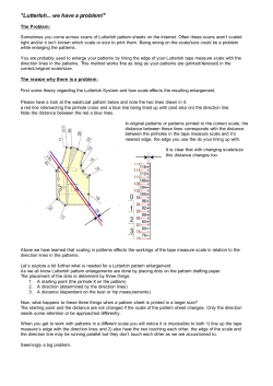


© Copyright 2026