
3 Material description 5/23/2014 3.1 Electrical cabinet
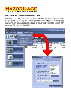
Version 7.1
5/23/2014
Page 11 of 93
3 Material description
POWER SUPPLY
380 – 420 VAC 50 Hz. or
440 – 480 VAC 60 Hz.
X8
X7
X6
Wiring the electrical cabinet (PLC cabinet)
X5
3.1.1
Electrical cabinet
X0
X1
3.1
BALLS WEIGHING CONTROLER
LOAD CELL CABLE
VIBRATOR
BALLS WEIGHING CONTROLER
110 – 120 VAC 60 Hz. Or 24 VDC
LOAD CELL CABLE
AIR PRESSURE STATUS
MAGOLOAD OPERATION ALLOWED
BALLS WEIGHING CONTROLER
LOAD CELL CABLE
VIBRATOR GATE OPEN LIMIT SWITCH
VIBRATOR GATE CLOSE LIMIT SWITCH
WEIGHING GATE OPEN LIMIT SWITCH
WEIGHING GATE CLOSE LIMIT SWITCH
MAGOLOAD STATUS
BIN WEIGHING CONTROLER
LOAD CELL CABLE
BIN STATUS
ALARM
BIN WEIGHING CONTROLER
LOAD CELL CABLE
VIBRATOR GATE OPEN VALVE
VIBRATOR GATE CLOSE VALVE
MILL POWER
(4-20 mA)
WEIGHING GATE OPEN VALVE
MILL FEED RATE(4-20 mA)
WEIGHING GATE CLOSE VALVE
Version 7.1
5/23/2014
Page 12 of 93
3.1.2
Power supply
The electrical cabinet containing the local user interface and the PLC is supplied with 3 x 380Vac –
420 Vac 50 Hz or 3 x 440Vac - 480 Vac 60 Hz from the customer electrical sub-station.
3.1.3
Plant signals connections
The system needs two analogical signals and two digital signals to work properly:
- Mill absorbed power:
4-20 mA Analogical input – can also come from the network.
- Mill feed rate:
4-20 mA Analogical input – can also come from the network.
- Magoload® operation allowed:
24 Vdc Digital or 110 – 120 Vac 60 Hz input
This signal is crucial as it prevents the balls from loading when the mill is standing.
It must be hardwired.
It can come from the mill itself if Magoload® directly feeds the mill or from a
conveyor belt if Magoload® feeds the mill through a conveyor belt.
- Mill running signal:
24 Vdc Digital or 110 – 120 Vac 60 Hz input – can also come from the network.
This signal is necessary to run the SEMI AUTOMATIC mode.
In this working mode the ball addition set point is defined by two parameters:
(1) The batch target (kg or lbs): How many balls are loaded at a time.
(2) The ball wear rate (kg/h or lbs/h): How many balls must be loaded per
mill running hour.
We will thus perform a ball addition of batch target (kg) every Batch Target
/ Ball wear rate (min).
Note : This signal is not the same as Magoload® operation allowed because if
Magoload® feeds the balls through a conveyor belt, the conveyor can be stopped
and thus also Magoload®. However the mill would be running and so the balls
would need to be loaded.
If one of those signals is available they will be tighten together.
Version 7.1
5/23/2014
Page 13 of 93
3.1.4
Powering and testing with the local electrical cabinet
1. Powering the emergency stop module
Check that all breakers in the local electrical cabinet are off.
Check that you have 3 x 380Vac – 420 Vac 50 Hz or 3 x 440Vac - 480 Vac 60
Hz. between the points L1, L2, L3 on the terminal X0.
Switch on the general breaker SG2.1
Switch on the breaker QM2.3 to supply the motor.
Switch on the breaker QM3.2A to supply the control power supply T.3.1.
Check the power supply T.3.1 outputs 24Vdc.
Switch on the breaker Q3.2D to supply the local electrical cabinet.
The emergency module P.3.4 is then powered.
2. Powering the Local user interface and the PLC
Check that the PLC key is on “RUN” position.
Pull off emergency push button AU3.6 located on the door.
Press the POWER push button BP.3.5 located on the door, this POWER push
button allows to rearms the system, reset the emergency module located
inside the power cabinet
if the emergency module is OK, the light H8.1
(power supply on the front door) turns on.
Switch on the breaker QM3.2A to supply the control power supply T.3.
Check the power supply T.3.1 outputs 24 V DC.
Switch on the breaker QM3.2D to supply’s:
• P.4.0 : Siemens PLC, 314C-2DP (Profibus, DI24/DO16 + AI5/AO2).
• P.12.1: Siemens local interface, OP77A.
• P.3.4: Siemens, Security relay.
Version 7.1
5/23/2014
Page 14 of 93
3.1.5
Design of the local electrical cabinet front panel
H8.1
H8.2
H8.3
H2.1
BP11.8
BP11.6
BP11.5
BP11.4
BP2.8
BP3.5
S2.8
SG2.1
AU3.6
Version 7.1
5/23/2014
Page 15 of 93
Description of the cabinet buttons
•
•
•
•
•
•
•
•
AU3.6: EMERGENCY STOP, this button allows switching off the electrical power and
completely stopping Magoload®.
BP3.5: this button allows to power up Magoload® cabinet and recognizes the alarms.
S2.8 : this key switch allows to select the maintenance mode, this maintenance mode
allows the manual control of Magoload® (without using the PLC)
BP2.8: this button allows vibrating in bypass PLC mode.
BP11.4: this button allows opening the vibrator gate in maintenance mode.
BP11.5: this button allows closing the vibrator gate in maintenance mode.
BP11.6: this button allows opening the weighing gate in maintenance mode.
BP11.8: this button allows closing the weighing gate in maintenance mode.
Description of the cabinet lights
•
•
•
•
•
•
•
•
H8.1: on when the emergency module is powered and rearmed.
H8.2: on when the bin is empty or full.
H8.3: on when a new alarm appears.
BP2.8: on when the vibrator is running.
BP11.4: on when the vibrator gate is opened.
BP11.5: on when the vibrator gate is closed.
BP11.6: on when the weighing gate is opened.
BP11.8: on when the weighing gate is closed.
Version 7.1
5/23/2014
Page 16 of 93
3.1.6
Before testing
Before starting the tests by pushing the buttons, don’t forget to:
a) Turn the key switch S2.8 (BYPASS PLC MODE) on “MAINTENANCE” position.
b) Turn the PLC (S7 1200) key on “RUN” position to be sure to activate the lights with the
PLC.
Switch on the breaker QM3.2 of the vibrator in the cabinet and use the push buttons (BP2.8) on the
front door of the cabinet to start the vibrator.
Note:
The adjustment of the vibration intensity in "MAINTENANCE
Mode" is done using the potentiometer “MAINTENANCE
VIBRATOR SET POINT” (P.2.6.) being in the electrical
cabinet.
Use the push buttons on the cabinet front door, to open and close the vibrator gate and look at the
corresponding lights on the front panel (it helps you to see if the limit switches of the vibrator gate
are working properly).
Use the push buttons on the cabinet front door to open or close the weighing gate and look at the
corresponding lights on the front panel (it helps you to see if the limit switches of the weighing gate
are working properly).
Version 7.1
5/23/2014
Page 17 of 93
3.2
3.2.1
Adjustment of the electro distributor & the limit switch of the pneumatic
actuator.
Assembling and wiring the electro-distributor of the two pneumatic
actuators.
Fig. 1
We can see on this photo:
•
•
•
The pneumatic actuator for the opening/closing of the vibrator gate
The pneumatic actuator for the opening/closing of the weighing gate
The electro distributor and its 2 coils on each one of the pneumatic actuator
Note:
For the assembly of the pneumatic actuator and coils, we can see the pneumatic actuator will be
placed in such manner to have the flow controls valve in top. The electro distributor will be
mounted on the front face to ease the assembly and the maintenance. Check to have the mark 12
(connection of the coil) on the left of the electro distributor and the mark 14 on the right side.
Version 7.1
5/23/2014
Page 18 of 93
3.2.1.1
Electric wiring of the electro-distributor
The explanations which follow are valid for the 2 pneumatic actuators.
Here the representation of the electro distributor used (MFH-5/3-1/4-B)
On picture 1, we can see:
•
•
The coil which is placed into 12 will command the closing of the gate.
The coil which is placed into 14 will command the opening of the gate.
We have the following wiring:
•
•
•
•
The W.11.3 cable will be placed on the coil and will command the opening of the vibrating
gate (14).
The W.11.4 cable will be placed on the coil and will command the closing of the vibrating gate
(12).
The W.11.6 cable will be placed on the coil and will command the opening of the weighing
gate (14).
The W.11.8 cable will be placed on the reel and will command the closing of the weighing
gate (12).
Version 7.1
5/23/2014
Page 19 of 93
3.2.1.2
Pneumatic wiring.
The explanations which follow are valid for the 2 pneumatic actuators.
Here the pneumatic wiring of the actuators (Refer to the pneumatic diagram).
We can see that:
•
•
•
The air flow will be connected on the terminal n°1 of the electro distributor tanks to a right
connection.
The exhaust of the air will be done through silencers with the holes n°3 and n°5.
The exit n°2 will be connected to the air intake b eing on the actuator (allowing the re-entry of
the actuator). For that, will be necessary:
A union elbow (to leave it the electro distributor).
A flow control valve (for the entry on the actuator).
A reducer with joint (for the entry on the actuator).
The exit n°4 will be connected to the air intake b eing on the actuator (has the
end of the cylinder and allowing the exit of the cylinder). For that, it will be
necessary:
A union elbow (to leave it the electro distributor).
A flow control valve (for the entry on the actuator).
A reducer with joint (for the entry on the actuator).
Version 7.1
5/23/2014
Page 20 of 93
3.2.1.3
Test.
To test our actuator, it will be necessary:
•
•
•
To have the clean instrumentation compressed air connected to the machine.
To power the electrical cabinet
To be in maintenance mode.
We can then check the electrical cabinet front door push buttons functionalities.
•
•
•
•
BP11.4: This button will order the opening of the vibrator gate.
BP11.5: This button will order the closing of the vibrator gate.
BP11.6: This button will order the opening of the weighing gate.
BP11.8: This button will order the closing of the weighing gate.
Verify the electric and pneumatic wiring if something goes wrong.
3.2.1.4
Speed regulation of opening/closing of the actuator.
The speed regulation of opening and closing will be done thanks to the small screw being on the
top of the flow control valve.
Adjust the air flow to control the speed of the door opening
and closing by trials and errors.
Too much flow will cause shocks on the door and not
enough flow will let the balls continuing to fall into the
weighing system.
Version 7.1
5/23/2014
Page 21 of 93
3.2.2
Assembly and wiring of the limit switch of the two actuators.
3.2.2.1 Presentation
The limit switch:
• Actuates the indicator lamps being on the front face of the electrical cabinet.
• Tells the PLC the state of the door and permits to detect possible defects.
VIBRATOR GATE OPEN LIMIT SWITCH (W5.7)
VIBRATOR GATE CLOSE LIMIT SWITCH (W5.8)
Version 7.1
5/23/2014
Page 22 of 93
They are mechanical limit switch.
Two limit switches will be placed on each door in order to be able to determine their position (open
or closed).
Those will be actuated by mechanical cams at the time of the opening or closing of the gate.
3.2.2.2
Wiring of the limit switch
We will use the limit switch of the brand Télémécanique "XCM102". The head will be a small caster
which will be inserted to make contact.
This limit switch is provided with a contact normally open and a contact normally closed.
13
21
14
22
For our application, we will use the normally open contact:
•
•
If the cam is not against the limit switch => = 0
If the cam is against the limit switch => = 1
3.2.2.3
Adjustment of the limit switch positioning
For this test, it will be necessary:
•
•
•
To have the clean instrumentation compressed air connected to the machine.
To power the electrical cabinet
To be in maintenance mode.
Then, we will actuate the gates in the two positions in order to check that the cam, once arrived at
end stop (opened and closed) make well contact with this module.
NOTE:
It is necessary that the contact between the cam and the limit switch arrives as late as possible to
be sure the gate is in position
Version 7.1
5/23/2014
Page 23 of 93
3.2.2.4
Test of the limit switch positioning
To test the correct operation of these elements we will use the indicator lamps on the electrical
cabinet. When the limit switch is activated, its indicator lamp on the electrical cabinet (light of the
pushbutton) must be on.
•
•
•
•
BP11.4: This light will be on when the vibrator gate is open.
BP11.5: This light will be on when the vibrator gate is closed.
BP11.6: This light will be on when the weighing gate is open.
BP11.8: This light will be on when the weighing gate is closed.


© Copyright 2026