
Template-based geometric transformations of a functionally enriched
1
Template-based geometric transformations of a functionally enriched
DMU into FE assembly models
Flavien. Boussuge1,2, Ahmad. Shahwan2, Jean-Claude. Léon2, Stefanie. Hahmann2, Gilles. Foucault2 and
Lionel. Fine1
EADS – Innovation Works, [email protected], [email protected]
Grenoble University/INRIA, [email protected], [email protected],
[email protected], [email protected]
1
2
ABSTRACT
Pre-processing of CAD models derived from Digital Mock-Ups (DMUs) into finite
element (FE) models is usually completed after many tedious tasks of model
preparation and shape transformations. It is highly valuable for simulation engineers
to automate time-consuming sequences of assembly preparation processes. Here, it is
proposed to use an enriched DMU with geometric interfaces between components
(contacts and interferences) and functional properties. Then, the key concept of
template-based transformation can connect to assembly functions to locate consistent
sets of components in the DMU. Subsequently, sets of shape transformations feed the
template content to adapt components to FE requirements. To precisely monitor the
friction areas and the mesh around bolts, the template creates sub-domains into their
tightened components and preserves the consistency of geometric interfaces for the
mesh generation purposes. From a user-selected assembly function, the method is able
to robustly identify, locate and transform groups of components while preserving the
consistency of the assembly needed for FE models. To enlarge the scope of the
template in the assembly function taxonomy, it is shown how the concept of
dependent function enforces the geometric and functional consistency of the
transformed assembly. To demonstrate the proposed approach, a business oriented
prototype processes bolted junctions of aeronautical structures.
Keywords: Assembly, DMU, CAD – CAE integration, Functional information.
DOI: 10.3722/cadaps.2013.xxx-yyy
1
NOTATIONS - ACRONYMS
General purpose acronyms:
BC: boundary condition;
DMU: digital mock-up;
FE: finite elements; FEA: finite element analysis(es);
KBE: Knowledge-based engineering;
PDP: product development process;
OWL: web ontology language;
Computer-Aided Design & Applications, 10(a), 2013, bbb-ccc
© 2013 CAD Solutions, LLC, http://www.cadanda.com
2
RDF: resource description framework;
STEP: Standard for the Exchange of Product model data;
Acronyms specific to the paper:
CI: conventional interface; CIG: conventional interface graph;
CC: compatibility conditions between T and ST;
FD: functional designation of a component;
FI: functional interface;
IC: set of components such that each of its components has all its FIs in T;
PC: set of components such that each of its components has some of its FIs in T;
TCI: taxonomy of conventional interfaces;
TFD: taxonomy of functional designations of components;
TFI: taxonomy of functional interfaces;
TFN: taxonomy of functions;
SME: reference state expressing static mechanical equilibrium of a component;
SLC: reference state expressing a static load cycle inside an assembly;
ST: shape transformation incorporated in a template, hence ST(T); ST1 : removal of a threaded
link; ST2: cylindrical sub domain around a screw shaft to localize friction effects; ST3: removal
of the locking nut of a bolted junction; ST4: screw head transformations; ST5: preserve the
cylindrical loose fit between screw and plates to set up contact friction BCs;
T: function-based template performing shape transformations;
TI: union of all components belonging to IC.
2
INTRODUCTION
To speed up a PDP, aeronautical, automotive and other companies face increasing needs in setting up
FE simulations of large sub-structures of their products. The challenge is to study not only standalone
components but to simulate the structural behavior of large assembly structures containing up to
thousands of components [9]. DMUs are widely used during a PDP as the virtual geometric product
reference. This model contains detailed 3D representation of the whole product structure available for
simulation engineers. To prepare large sub-structure models for simulation (such as wings or aircraft
fuselage section); the DMU offers a complete geometric input model. However, speeding up the
simulation model generation strongly relies on the time required to perform the geometric
transformations needed to adapt the DMU to FE requirements.
Currently, time and human resources involved in pre-processing CAD models derived from DMUs
into FE models prevent engineers from setting up structural analyses. Very tedious tasks are required
to process the large amount of DMU components and the connections between them. The shape
transformations required for each assembly component, and interactively performed by engineers, can
cover defeaturing [15, 35], idealization [5, 6], domain decomposition [28, 30] as well as the definition
of contact areas. Even on repetitive configurations such as junctions, similar geometric
transformations must be repeated on all the components and interfaces of all the assembly junctions.
Aeronautical structures are particularly complex to transform due to their many independent
connectors such as bolts or rivets (see Fig.1). Even though CAE software possess specific operators for
bolted junctions, pre-stressed configurations, …, to speed up FEA pre-processing, the user must
already have available a DMU incorporated all the desired geometric transformations. Automated
domain decomposition, geometric simplifications, selection of target components are examples of
functions still interactive and error prone that a user must perform tediously. Within the available
resources and time scale planned in an industrial PDP, the analyst is therefore limited to simulate
small models rather than complete assembly structures.
Computer-Aided Design & Applications, 10(a), 2013, bbb-ccc
© 2013 CAD Solutions, LLC, http://www.cadanda.com
3
Fig. 1: Examples of aeronautical DMUs with a variety of bolted junctions.
Compared to standalone components, the above observations highlight the prominence of
geometric interfaces processing when preparing an assembly model for FEA. Their mechanical
behavior and the new shape transformations they convey are specific features of assemblies [9]. As
described in [34], component’s geometric interfaces are the basis of component’s functional
designation. Effectively, to speed up the transformation of a DMU into a FE model, the engineer would
process the components in accordance to their mechanical effect in the assembly, i.e. their function.
Consequently, the relationship between FE simulation hypotheses, component’s functions and
component’s interfaces appears as a key issue to improve the efficiency of DMU transformation for
FEA. Indeed, setting up a FEA aims at studying the mechanical behavior of an assembly. Function,
behavior and shape share strong connections, as studied by Gero [17, 18] and Albers [1, 2] among
others, hence the aforementioned example of the FE preparation process contributing to the
representation of bolted connections in an aeronautical assembly.
In this paper, we propose an approach to reduce the FE model preparation time to adapt CAD
assembly models derived from DMUs, into FE assembly models. Based on the analysis of DMU
transformation requirements for FE assembly model preparation [9], the method uses an enriched
DMU as input. It is obtained from previous developments and contains explicit geometric interfaces
between components (contacts and interferences) as well as their functional designations. This last
step is achieved using a qualitative reasoning process. From this enriched model, it is shown that
further enrichment is needed to reach a level of product functions where simulation objectives can be
used to specify new geometric operators that can be robustly applied to automate components’ and
interfaces’ shape transformations during an assembly preparation process for FEA. If close to KBE, this
scheme is nonetheless more generic and more robust than KBE approaches because functional
designations and functions are generic concepts. KBE aims at structuring engineering knowledge and
processing it with symbolic representations [39, 40] using language based approaches. Here, the focus
is on a robust connection between geometric models and symbolic representations featuring
functions.
To prove the validity of our approach and the methodology proposed in [4-9], this paper presents
a template-based operator dedicated to automate shape transformations of bolted junctions. Using the
functional information and geometric interfaces, the operator applies a user-defined template to
simplify bolts and sets control sub-domains around them in their associated tightened components to
enable the description of the friction phenomenon between these components. This template is used
to precisely monitor the meshing process while preserving the consistency of contacts and adapting
the assembly model to simulation objectives.
The rest of the paper is organized as follows. In Section 2, we review the CAD-CAE integration
research for FE assembly models. Section 3 reviews the method to enrich the DMU with geometric
interfaces between components and functional designations of components. New requirements are
introduced to connect functional designations with functions. Section 4, describes the concept of
template-based transformation operator and illustrates it with a template-based operator of bolted
Junctions transformation. Finally, the paper presents the result of this operator on an industrial
aeronautical use-case and section 5 exemplifies an extension of the template definition with
idealization transformations.
Computer-Aided Design & Applications, 10(a), 2013, bbb-ccc
© 2013 CAD Solutions, LLC, http://www.cadanda.com
4
3
RELATED WORK
Assembly models have been studied throughout the development of solid modeling concepts.
Essentially, assembly models have been proposed for design and manufacture applications [29-32] with
recent applications to collaborative design. With the development of features, approaches set
assemblies as components related to each other through geometric constraints [38]. These approaches
share a common denominator where assemblies are described as geometric models progressively
enriched with technological and then, functional data [14]. However, the closer the functional
information, the higher is the requirement to obtain external information to CAD environments and
the greater is the need of user’s interactions during a design process. Though these additional
informations are mandatory in a design process, it does not seem efficient to incorporate them into a
preparation process for FE simulation when time reduction is critical to insert simulations into a PDP.
If these informations were available at the level of FE simulation, a dedicated approach could be set up
to process them but companies are currently not able to set up a digital representation of these data
that is connected to the DMUs they produce with CAD systems. Within this framework, Roy and
Bharadwaj [31] set up a design approach to connect functions to 3D geometry using a Part Function
Model (PFM). There, they address the relationships between function, behavior and geometry of a part
in a top-down manner from function to geometry to obtain parts from functional specifications. The
PFM described requires up to low level functions that connect part boundary faces to function since
the behavior model builds up on interfaces between parts, i.e. contact surfaces to position parts with
respect to each other. At the level of complex assemblies with hundreds to thousands of parts, adding
the amount of complementary data defining such a behavioral model becomes too tedious. Recent
approaches [24] reduce the description of junctions between components to global parameters
describing bolted and riveted connections without referring to the individual surfaces of each bolt or
rivet. This fits well with a design process but simulation objectives may require a detailed
representation of interfaces when the purpose is to assess the stress field distribution in a bolted
connection with tens or hundreds of bolts.
Developments of ontology-based approaches take advantage of new capabilities to structure
concepts and to connect them with component models [25, 29] or at the level of 3D geometry entities
[7-19]. Some of these approaches have been applied to assemblies [7, 22, 29] and can take advantage of
reasoners to set up inference rules to ensure the consistency of the assembly description or extract
information that is not readily available in the dataset describing an assembly. In [22, 29], there is no
direct connection between the ontology content and the 3D model of components. Here, ontologies
support a design process where the engineer gets consistent information in a collaborative context but
the ontology does not connect to boundary entities of component geometric models. Barbeau et al. [7]
cover a larger description of a product with an ontological description incorporating the geometry and
structure levels as available through STEP APIs [20, 21], up to the functional description that can be
inserted through ontological representation of the Core Product Model (CPM) [16]. The authors showed
that not all concepts of STEP could be rigorously expressed using OWL standard [27] leading to
limitations in detecting inconsistencies. If CPM is able to relate component functions to form features,
the content of the CPM reflects the designers' choices to determine the level of product features
inserted in this model and its level of connection with each component’s geometry. Consequently,
there is no guarantee that functional information can be available downward to the level of B-Rep
entities of each component. Reasoning capabilities associated with ontologies are set up to browse the
whole assembly ontology but they are not applied to derive new functional information or reinforce
the connection between function and geometry in an assembly model. Consequently, we can observe
that assembly processing is often addressed in a design context of top-down approach from primary
product function point of view and there is no low level robust connection between components'
geometry and low level functions. Additionally, the reasoning capabilities of ontology-based
approaches are exploited to browse existing assembly data and derive data not readily available. These
reasoning processes do not extend further than relative positioning constraints between components.
KBE approaches [39, 40] formalize engineering knowledge to automate some design tasks. KBE
concepts take advantage of artificial intelligence techniques and strongly rely on language-based
approaches. As such, they follow top-down approaches based on enterprise ‘best practices’ and
address preliminary design stages rather than embodiment or detailed design ones, which is the
Computer-Aided Design & Applications, 10(a), 2013, bbb-ccc
© 2013 CAD Solutions, LLC, http://www.cadanda.com
5
product geometric description addressed here with DMUs. This is hardly applicable to other
companies and even more to other products. Still, if KBE approaches incorporate connections with
geometric models, geometry is perceived as attribute of higher level concepts like components, which
does not bring new structure to the geometric models of components. Recently, Shahwan et al. [34]
inserted a qualitative reasoning process that can relate geometric interfaces up to the functional
designation of components, thus creating a robust and automated connection between 3D geometric
entities and functional designations of components. It is a bottom-up approach that fits to our current
requirements.
Research in CAD-CAE integration has mainly focused on the use of global geometric
transformations of standalone CAD components [35]. Few contributions addressed the automation of
assembly pre-processing. Automatic simplifications of assembly for collaborative environment as the
multi-resolution approach of Kim [23] or surface simplification of Andujar [3] transform assembly
components independently of each other. This is not sufficient to pre-process FE assembly models
because mechanical joints and interfaces tightening the different components must be part of their
pre-processing. Commercial software proposes to automatically detect geometric interfaces between
assembly components. However, their algorithms use a global proximity tolerance to find face pairs of
components and they don’t produce explicitly the geometric model of their contact area. In the
assembly simplification method of Russ et al. [33], the authors propose to set components
dependencies to remove groups of components having no influence on a simulation or to replace them
by defeatured equivalent ones. However, the parent/child relationships created from constraint
placement of components do not guarantee to obtain the entire neighborhood of a component because
these constraints are not necessarily related to the components’ geometric interfaces. In addition,
DMUs don’t contain components’ location constraints when assemblies are complex, as occurring in
the automotive and aeronautic industries, to ease design modifications during a PDP. Moreover, part
naming identification used in this approach is not sufficient because it locates only individual
components contained in the assembly without establishing relations with their adjacent components
and their associate geometric model, i.e. replacing a bolted junction by an idealized fastener implies
simplifying its nut, its screw as well as the hole connected to them in the tightened components. To
provide mesh domains connectivity, Lou [26] and Chouadria [10] proposes to identify and re-mesh
contact interfaces. Quadros [28] establishes sizing functions to control assembly meshes. However,
these methods are used directly on already meshed models, which addresses specific PDP
configurations where CAD models are not readily available. Clark [11] detects interfaces in CAD
assemblies to create non-manifold models before mesh generation but does not consider the
interactions between interfaces and components’ shapes transformation processes. In [9], we
underline that if a component is simplified or idealized, its shape transformation has an influence on
the transformation of its neighbors, e.g. a component idealized as a punctual mass impacts its
neighboring component interfaces.
Indeed, to adapt an assembly to FEA requirements, geometric transformations derive from
simulation objectives and components’ functions are needed to geometrically transform groups of
components. It is also critical to structure the geometric models of components so that their shape
transformations can preserve the DMU consistency [9]. We propose an approach where a DMU is
enriched with geometric interfaces between its components, i.e. contacts and interferences, and
functional properties. From this enriched model, simulation objectives can be used to specify
geometric operators that can be robustly applied to automate components and interfaces shape
transformations during an assembly preparation process.
4
4.1
DMU ENRICHMENT WITH FUNCTIONAL INFORMATION
From a component geometry to its functional designation
The principle of DMU functional enrichment can be summarized with the process flow shown on Fig. 2.
Its detailed description can be found in [34]. The focus is placed on this approach because, to the
Computer-Aided Design & Applications, 10(a), 2013, bbb-ccc
© 2013 CAD Solutions, LLC, http://www.cadanda.com
6
authors’ knowledge, Shahwan’s approach can automatically produce a functionally enriched DMU from
a pure geometric input model, which is the reliable input data addressed here.
Fig. 2 starts from the STEP [20, 21] representation of an assembly model with the extraction of
geometric interfaces between components. Two categories of interfaces are addressed: contacts
(surface and line ones) and interferences. The latter originates from the conventional representations
of components, e.g. a screw is represented with a threaded part defined as a cylinder whose diameter
equals the outer diameter of the thread and its nut is represented with a threaded part defined as a
cylinder whose diameter equals an inner diameter of the thread; this produces a geometric
interference between these components. At this stage, each component boundary gets modified to
incorporate the imprints of its neighboring components through contacts and interferences. The
geometric interfaces feed instances of ‘conventional interfaces’ (CI) classes structured into a taxonomy,
TCI, that binds geometric and symbolic data, e.g. planar contact, spherical partial contact, cylindrical
interference, … Simultaneously, CIs and assembly components are organized into a CI graph: CIG(C, I)
where the components C are nodes and CIs I are arcs.
TCI
(SME, SLC)
TFI
TFD
Fig. 2: Process flow to enrich a DMU with functional designations of components and their associated
structured geometric models.
Then, instances of functional interfaces (FIs) are derived from CI ones, possibly with multiple
instances of FIs originated from a single instance of CI, e.g. a cylindrical contact can become either a
cylindrical loose fit or cylindrical tight fit but a planar contact becomes only a planar support.
Instances of FIs fit also into a taxonomy TFI. Now, the duality between geometry and interaction forces
is used to derive mechanical parameters, i.e. screws (resulting force, resulting moment), from each
instance of FI. These parameters are expressed qualitatively and feed symbolic behaviors of the
assembly in order to take advantage of the shape, behavior, function relationship [1, 2, 17, 18].
Assembly behaviors are characterized by reference states and aim at reducing a single FI instance per
CI instance. Here, two reference states are of interest: the mechanical equilibrium reference state, SME,
and the static load cycle one, SLC. SME expresses the fact that each component must hold tight when the
assembly has no mechanical interaction with its environment, i.e. each component can satisfy the
static equilibrium equations. SLC expresses the fact that any threaded link between any two
components of an assembly must generate close loops of forces, i.e. force cycles so that the
corresponding components stay at static equilibrium. Fig. 3 illustrates this concept with a bolted
junction and a force cycle in magenta.
Computer-Aided Design & Applications, 10(a), 2013, bbb-ccc
© 2013 CAD Solutions, LLC, http://www.cadanda.com
7
Fig. 3: Example of force cycle, as subset of the CIG, initiated by a threaded link.
Force cycles symbolically express the effect of a threaded link throughout an assembly, which
ends up with the identification of sub graphs of the CIG defining the effect of each threaded link.
Now, a matching process takes place based on a taxonomy of functional designations of
components, TFD. A functional designation of a component is an unambiguous denomination that
functionally distinguishes one class of components from another. It relates the geometric model of a
component, its FIs and FIs of its functionally related components, e.g. those contained in a load cycle,
to its denomination. The functional designation of a component binds the 3D model of a component
and FIs to a symbolic representation of its functions. Regarding screws, examples of functional
designations are: cap screw, locked cap screw, set screw, stop screw, … The matching process is set up
using inferences processed by a reasoner, FACT++, that can be connected to OWL or RDF [27]
descriptions of the instances of FIs attached to a given component. The inferences characterize the
necessary properties of FIs that a component must satisfy to belong to a given functional designation.
As a result, components models as well as their geometric model get structured, i.e. their 3D
model contain imprints of their FIs and geometric relationships with FIs of functionally related
components; FIs contain the lowest symbolic information describing the elementary functions of a
component and each functional designation expresses uniquely the necessary relations between these
elementary functions. Fig. 4 illustrates this result with a cap screw.
Fig. 4: Structuring the model of a component with functional properties after analyzing its geometric
interactions and assigning it a functional designation, here a ‘cap screw’.
4.2
From components’ functional designations to functions
Though the bottom-up approach summarized in the previous section provide assembly components
with a structured model incorporating functional information that is independent of their dimensions,
their functional designation does not appear as an appropriate entry point to derive shape
transformation operators as required for FE analyses. Indeed, to set up FE assembly models, an
engineer looks for bolted junctions that he, resp. she, wants to transform to express friction
phenomena, pre-stressed state in the screw, … Consequently, the functional level needed is not the
functional designation, which is bound to a single component, it is the function itself to address the
corresponding set of components and their FIs.
Computer-Aided Design & Applications, 10(a), 2013, bbb-ccc
© 2013 CAD Solutions, LLC, http://www.cadanda.com
8
To this end, it is mandatory to refer to functions. This is achieved with a taxonomy of functions,
TFN, that can produce a functional structure of an assembly (see Fig. 5). Blue items define the sub-path
in TFN hierarchy that characterizes bolted junctions.
Fig. 5: Subset of TFN, defining a functional structure of an assembly.
Each instance of a class in TFN contains a set of components identified by their functional
designation, i.e. it contains their structured geometric models and FIs. The generation of these
instances takes advantage of the functional designations of components, e.g. adjusted cap screw in the
present case, and the load cycles attached to them and derived from SLC. This generation is achieved
with inferences on functional designations and properties of load cycles. To this end, it is mandatory
to distinguish statically determined configurations from statically undetermined ones. These details
are not described here to preserve the paper consistency and concentrate on the exploitation of these
functional informations.
As a result of the use of TFN, a component of a DMU can be automatically identified when it falls
into the category of cap screws, nuts, locking nuts that are required to define bolted junctions. This
means that their B-Rep model incorporates their geometric interfaces with neighboring components,
the graph of interfaces identifies the components a bolted junction contains, the components are
assigned functional designations that intrinsically identifies cap screws, nuts, locking nuts, …, and
connects them with and assembly instance in TFN.
It is now the purpose of the next section to take advantage of this information to set up the
template-based transformations.
5
TEMPLATE-BASED TRANSFORMATIONS FOR FE MODELS
As a result, the DMU is now geometrically structured, components are linked by their geometric
interfaces, and groups of components can be accurately identified and located in the DMU using their
function and geometric structure, e.g. ‘adjusted bolted junctions with screw+nut’ (see Fig. 5). Now, the
geometric transformations needed to adapt the DMU to FEA objectives are strengthened because
screws, nuts, locking nuts can be robustly identified, groups of tightened components are also
available through the load cycles attached to cap screws.
Two possible accesses are proposed to define a function-based template related to an assembly
function:
-
A component through a user-defined selection: from it and its FD, a datastructure gives access
to the functions it contributes to. After selecting this component, the user selects the
function of interest. Other components are recovered through the selected function this
component participates to,
-
The function itself that can lead to the set of components needed to define this function and
all the instances of this function existing in the targeted assembly.
These accesses can be subjected to constraints that can help identifying the proper set of instances.
Constraints aim at filtering out instances when a template is defined from a function to reduce a set of
instances to the user’s needs, e.g. assembly function with bolts ‘constrained with’ tightening plates
‘plate_i’ and ‘plate_j’ where these designations are functional designations of these components.
Computer-Aided Design & Applications, 10(a), 2013, bbb-ccc
© 2013 CAD Solutions, LLC, http://www.cadanda.com
9
Constraints aim at extending a set of instances when a template is defined from a component, i.e. a
single function instance recovered, and needs to be extended, e.g. assembly function with bolts
‘constrained with’ same tightened components and screw head FI of type ‘planar support’ or ‘conical
fit’.
5.1
Function-based template and compatibility conditions of transformations
The previous paragraph has sketched how component functions can be used to identify sets of
components in an assembly. Indeed, this identification is based on classes appearing in TFN. Here, the
purpose is to define more precisely how the template can be related to TFN and what constraints are set
on shape transformations to preserve the geometric consistency of the components and assembly.
Shape transformations are application-dependent and the present context is structural mechanics and
FEA to define a range of possible transformations.
The simplest relationship between a template T and TFN is to relate T to a leaf of TFN. In this case, T
covers instances defining sets of components that contain a variable number of components. T is also
dimension independent since it covers any size of component, i.e. it is a parameterized entity. Shape
transformations on T are designated as ST and the template devoted to an application becomes ST(T).
Now, reducing the scope to disassemblable assembly functions and more specifically bolted junctions,
one leaf of TFN can be used to define more precisely T and ST(T). Conforming to Fig. 5, let us restrict
first to the leaf ‘screw+nut’ of TFN. Then, T contains the following FIs: one threaded link, two or more
planar supports (one between nut and plate and at least one between two plates), either one planar
support or one conical fit between the screw head and a plate, as many cylindrical loose fits as plates
between the screw and plates because the class of junctions is of type adjusted. The shape
transformations ST(T) of T set up to process bolted junctions can be summarized as:
-
ST1: merging screw and nut;
-
ST2: localization of friction effects with a sub domain around a screw;
-
ST3: removal of locking nut if it exists;
-
ST4: screw head transformation for mesh generation purposes;
-
ST5: cylindrical loose fit around the screw shaft to support the contact condition with tightened
plates.
Each of these transformations will detailed throughout the following sections.
Now, the purpose is to define ST so that ST(T) exists and preserves the consistency of the
components and the assembly. This defines compatibility conditions, CC, between T and ST that are
conceptually close to attachment constraints of form features on an object [37]. CC apply to ST and are
introduced briefly here. Given the set of components contained in T, this set can be subdivided into
two disjoint subsets as follows:
-
IC is the set of components such that each of its components has all its FIs in T, e.g. the screw
belongs to IC. Consequently, components belonging to IC are entirely in T;
-
PC is the set of components such that each of its components has some of its FIs in T, e.g. a
plate belongs to PC. Components belonging to IC are partially in T.
IC can be used to define a 3D sub domain of T, TI defined as the union of all components belonging to
IC. Now, if a transformation ST takes place in IC and geometrically lies inside TI, ST(T) is valid because it
cannot create interferences with other components of the assembly, i.e. CC is satisfied.
Let us consider some of these transformations to illustrate some CC. As an objective of FEA, the
purpose of the assembly model is to analyze the stress distribution between plates and their
interactions with bolts. To this end, the stress distribution around the threaded link between a screw
and a nut is not relevant. Therefore, one shape transformation, ST1 is the removal of the threaded link
to merge the screw and the nut (see Fig. 6a). ST1 is always compatible since the screw and the nut
belong to IC, hence the validity of CC.
Computer-Aided Design & Applications, 10(a), 2013, bbb-ccc
© 2013 CAD Solutions, LLC, http://www.cadanda.com
10
Now, considering another transformation, ST2, is the localization of friction effects between plates
around the screw shaft and the representation of the stress distribution nearby the screw shaft. This is
modeled with a circular area centered on the screw axis and a cylindrical sub domain around the screw
shaft (see Fig. 6b). Indeed, ST2, is a domain decomposition [12, 13] taking place in the plates belonging
to T. Because the plates belong to PC, CC are not trivial. However, ST2, takes place inside the plates so
they cannot interfere with other components, rather they can interfere with the boundary of the plates
or they can interfere between them when several screws are close to each other on the same plate (see
Fig. 7). In this case, CC can be simply expressed, in a first place, as a non interference constraint.
Other shape transformations will be listed when describing one example template in section 4.4.
5.2
Shape transformations and function dependency
The previous section has connected T to TFN in the simplest way possible, i.e. using a leaf that
characterizes a single function. The purpose of this section is to analyze into which extent T can
connect to classes of TFN that perform several functions in the assembly.
In a first place, let us review shortly some concepts of functional analysis [36]. There, it is often
referred to several categories of functions that are related to a design process, i.e. external, internal,
auxiliary, … However, this does not convey consistency conditions among these functions, especially
from a geometric point of view. Here, the current content of TFN refers to internal functions, i.e.
functions strictly performed by components of the assembly. The ‘screw+nut’ function, as part of
bolted junctions, is one of them. Bolted junctions can contain other functions. Let us consider the
locking function, i.e. the bolt is locked to avoid any loss of tension in the screw when the components
are subjected to vibrations. The locking process can take place either on the screw or on the nut. For
the purpose of the analysis, we consider here a locking process on the nut, using a locking nut (see Fig.
9a). In functional analysis, this function is designated as auxiliary function but this concept does not
characterize geometric properties of these functions.
From a geometric point of view, it can be observed that FIs of the screw, nut and locking nut are
located in 3D such that the FI (planar support) between the nut and locking nut cannot exist if the nut
does not tighten the plates. Consequently, the locking function cannot exist if the tightening function
does not exist. Rather than using the designation of auxiliary function, which is geometrically
imprecise, it is referred to dependent function.
The concept of dependent functions is inserted in TFN at different levels of TFN to attach the
corresponding functions when they exist (see Fig. 5). Based on the concept of dependent function, it is
possible to extend the connection rule between T and TFN. Rather than connections at the leaf level,
higher level classes can be connected to T if the dependent functions are taken into account in the CC
of shape transformations ST so that ST(T) exists and preserves the consistency of the assembly. As an
illustration, let us consider T connected to ‘Bolted adjusted’ (see Fig. 5). Now, ST can cover the class of
bolted junctions with locking nut. Let ST3, be the transformation that removes the locking nut of a
bolted junction, which meets also the FEA objectives mentioned earlier. Because ST3, applies to a
dependent function of ‘screw+nut’, is satisfies the CC and the resulting model has a consistent layout
of FIs. Consequently, T can be effectively connected to ‘Bolted adjusted’, which is a generalization of T.
5.3
Template generation
T is generated on the basis of the components involved in its associated function in TFN. T incorporates
the objectives of the FEA to specify ST. Here, ST covers all the transformations described previously, i.e.
ST1, ST2, ST3. Fig. 6 and 7 illustrates the key elements of these shape transformations.
Computer-Aided Design & Applications, 10(a), 2013, bbb-ccc
© 2013 CAD Solutions, LLC, http://www.cadanda.com
11
IC :
Counter Nut
Nut
Screw
Threaded
Link
Pre-Load
Pressure
Domain
decomposition
Friction
PC :
Plates
ST3
ST1
ST2
ST4
(CC satisfied)
(CC satisfied)
(CC to verify)
(CC to verify)
Fig. 6: Compatibility conditions (CC) of shape transformations ST applied to T.
Other shape transformations, ST4, can be defined to cover screw head transformations and extend
the range of screws to flat head ones.
Then, the set of shape transformations structures the dialog with the user to allow him, resp. her,
to select some of these transformations. However, the user settings are applied to instances whenever
possible, i.e. when the instance belongs to a class where the shape transformations are applicable.
Ø Subdomains =
User Ratio X Ø Screw
User Meshing
Tolerance
No interference
Interference
Fig. 7: Checking the compatibility of ST(T) with respect to the surrounding geometry of T.
5.4
Example of template-based operator of bolted junctions transformation
During the PDP of an aeronautical company, simulation engineers perform specific FEAs on assembly
sub structures such as the aircraft junction between wings and fuselage. Based on pre-existing physical
testing performed by ROMMA project partners, this structure can be subjected to tensile and
compressive forces to analyze:
•
•
The distribution of the load transfer among the bolted junctions;
The admissible extreme loads throughout this structure.
(a)
(b)
Fig. 8: (a) Multi-scale simulation with domain decomposition around bolted junctions (b) Load transfers
at critical holes (courtesy of ROMMA project [4]).
Computer-Aided Design & Applications, 10(a), 2013, bbb-ccc
© 2013 CAD Solutions, LLC, http://www.cadanda.com
12
From the physical testing and preliminary numerical models, the following simulation objectives have
been set up that initiate the requirements for the proposed template-based transformations.
To adapt the FE model to these simulation objectives while representing the physical behavior of the
structure, an efficient domain decomposition approach [12, 13] uses a coarse mesh far enough from
the bolted junctions and a specific sub domain around each bolted junction with friction and preload
phenomena (see Fig.8a, b). The objective is not to generate a detailed stress distribution everywhere in
this assembly but to observe the load distribution areas among bolts using the mechanical models set
in the sub domains. The objective of this section is to validate the template-based approach based on a
demonstrator that transforms automatically the bolts into simplified sub domains ready for meshing
with friction area definition while preserving the consistency of the assembly. The template features
are aligned with the needs for setting up a simulation model able to exhibit some of the physical
phenomena observed during testing and expressed in the above simulations results.
5.4.1
Operator description
Having enriched the assembly with functional information, the template interface lets the user select a
node of TFN that is compatible with T. In this example, the function to select is: ‘assembly with Bolted
junction’ (see Fig. 10). Now, several ST are either pre set or user accessible. ST3 is user accessible and set
here to remove the dependent function ‘locking with locking nut’ because the simulation objective
does not focus on dynamic effects. Then, ST5 is pre set in T to preserve the cylindrical loose fit between
screw and plates to set up contact friction BCs without interpenetration over these FIs. ST1 is also pre
set as well as ST4. The latter is performed on the FI (planar support) between the screw head/nut and
the plates to obtain a meshing process independent of nut and screw head shapes. Now, T can cover
any bolted junction to merge screw, nut and locking-nut into a single domain, reduce the screw and
nut shapes to a simple shape of revolution while preserving the consistency of its interfaces. To
precisely monitor the stress distribution around bolts and friction between plates, ST2 is user-selected.
It a simplified model of the Rotscher’s cone [8] (see Fig.9) that enables generating a simple mesh
pattern around bolts.
Rotscher’s
Cone
(a)
Sub-Domains
(b)
Structured
Hex Mesh
(c)
Fig. 9: Template based transformation ST(T) of a bolted junction into simple mesh model with friction
and contact areas definition around screw and nut.
Based on T, ST(T) is fairly generic and parameterized to intelligently select and transform bolts, i.e.
it is independent of the number and thicknesses of plates, of the screw diameter, the length and head
type (cylindrical (see Fig. 9a) versus flat ones) in addition to the location of each bolt.
Here, ST(T) contains ST2, a generation of sub domains taking into account the physical effects of the
Rotscher’s cone. This geometric transformation could interact with plate boundaries to change the
shape of these sub domains and influence the mesh generation process. Presently, templates are
standalone entities and are not taking into account these effects left for future developments. At
present, the user can adjust the sub domain to avoid these interactions (see Fig. 10a).
Computer-Aided Design & Applications, 10(a), 2013, bbb-ccc
© 2013 CAD Solutions, LLC, http://www.cadanda.com
13
5.4.2
Implementation and results
The developed prototype is based on OpenCascade and Python scripting language. The DMU is
imported as STEP assembly models, the geometric interfaces between components are represented as
independent trimmed CAD faces with identifiers of the initial face pairs of the FI. The assembly
functional description is imported as a text file from the specific application performing the functional
enrichment described in [34] and linked to the assembly model by components’ identifiers.
Fig.10a shows the user interface of the prototype. When selecting the ‘assembly with Bolted
Junction’ function, the user has a direct access to the list of bolted junctions in the assembly. To allow
the user filtering his selection, DMU parameters are extracted from the FD of components, e.g. the
screw and nut type, the number of tightened components, or from geometry processing based on FDs,
e.g. screw diameter. Using these parameters, the user is able to select bolted junctions with diameter
between 10 and 16 mm (see Fig.10b) or bolted junctions with screw and locking nut (see Fig.10c), etc.
The user can monitor the Rotscher’s cone dimension with a FEA parameter called ‘sub domain ratio’
that represents the ratio between the screw nominal diameter and the sub-domain diameter (see
Fig.10d and e). Then, the user-defined ‘meshing tolerance’ is used during the verification phase to
check the compatibility conditions, CC, between instances and their surrounding geometry (see Fig.7).
Fig. 11 shows two results of the template-based transformations on aircraft structures:
1.
A junction between the wing and the fuselage. The assembly contains 45 bolted junctions
with 3 different diameters and 2 different screw heads;
2.
An engine pylon. The assembly contains over 250 bolted junctions with identical screws
and nuts.
(a)
(b)
(d)
(c)
(e)
Fig. 10: User interface for transformation of ‘assembly Bolted Junctions’ (a), filtering bolts based on
diameters (b) or screw type (c), template-based transformations with (d) or without (e) sub domains.
Computer-Aided Design & Applications, 10(a), 2013, bbb-ccc
© 2013 CAD Solutions, LLC, http://www.cadanda.com
14
(a)
(b)
(c)
Fig. 11: (a) CAD model with functional designations and geometric interfaces, (b) model after applying
ST(T) on bolts, (c) mesh assembly model with friction area definition.
The final CAD assembly (see Fig. 11b) with simplified bolted junctions has been exported to a
CAE software, i.e. Abaqus. STEP files transfer the geometric model and associated xml files describes
the interfaces between components to trigger meshing strategies with friction area definition.
Comparing with the process pipeline used with existing industrial software, the figures are as
follows. The model preparation from CAD software to Abaqus simulation model takes 5 days of
interactive work for aircraft structure 1 mentioned above. Using the pipeline performing the functional
enrichment of the DMU and the proposed template-based shape transformations, to directly produce
the meshable model in Abaqus and perform the mesh in Abaqus, the overall time is reduced to one
hour. The adequacy of this model conforms to the preliminary numerical models set up in ROMMA
project and extending this conformity to testing results is ongoing since the template enables easy
adjustments of the mesh model. Regarding the aircraft structure 2, there is no reference evaluation of
its model preparation time from CAD to mesh generation because it is considered as too complex to
fit into the industrial product development process. However, it is possible to estimate the time
reduction since the interactive time can be linearly scaled according with the number of bolted
junction. This ends up with 25 days of interactive work compared to 1.5 hour with the proposed
approach where the time is mostly devoted to the mesh generation phase rather than the templatebased transformations, which stay automated.
Though the automation is very high, the template-based approach leaves the user with
meaningful parameters enabling him/her to adapt the shape transformations to subsets of bolted
junctions when FE it is required models.
6
CONCLUSION
In this work, a template-based method empowers the use of DMUs enriched with geometric interfaces
and functional information, to automate CAD assembly pre-processing and generate a FE-friendly
equivalence of this assembly. Because the template is directly connected to assembly functions, its
instances contain a group of components consistently involved in the same assembly function. When
Computer-Aided Design & Applications, 10(a), 2013, bbb-ccc
© 2013 CAD Solutions, LLC, http://www.cadanda.com
15
selecting a specific function, the user has a direct access to the associated components, their
structured model as well as their FIs. It has been shown also that the template can cover a rather large
range of configurations since it is parameterized with respect to components’ dimensions,
components’ number, components’ shapes and finally, component function with the concept of
dependent function. Using the template-based transformations, the user can robustly and efficiently
define the geometric transformations according to his/her FEA objectives and meshing constraints.
Thus, new components’ shapes adapted to CAE software requirements are produced while the
consistency of the assembly model is preserved. The template can be instantiated over the whole
assembly to transform quickly repetitive configurations such as bolted junctions which were highly
time consuming with interactive processing. Finally, a demonstrator has been presented to prove the
efficiency of the template-based transformation approach and its valuable contribution to a PDP. The
template-based approach show how shape transformations highly benefit from functional information
and strengthen these transformations in the context of complex models like assemblies where many
components interact with each other. Bolted junctions of two industrial use-cases have been
automatically transformed into simplified macro elements with sub-domains generation. The resulting
model produces a seamless generation of FE models conforming to the simulation objectives while
taking into account meshing constraints.
7
ACKNOWLEDGMENT
This work is carried out as part of the ROMMA (RObust Mechanical Models for Assemblies) project [4]
under the reference ANR-09-COSI-012. The authors are very grateful for the financial support from the
Agence Nationale de la Recherche (ANR). This work is also supported by the ERC Expressive.
REFERENCES
[1]
[2]
[3]
[4]
[5]
[6]
[7]
[8]
[9]
[10]
[11]
Albers, A.; Braun, A.; Clarkson, P. J.; Enkler, H.-G.; and D. Wynn: Contact and channel modeling to
support early design of technical systems, Proc. Int. Conf., ICED’09, August, Stanford, USA, pp
61-72, (2009).
Albers, A.; Burkardt, N.; Ohmer, M.: Contact and Channel Model for Pairs of Working Surfaces, In
ElMaraghy, H. A., ElMaraghy, W. H. (Eds), London: Springer, Advances in Design, pp 511-520,
(2006), DOI: 10.1007/1-84628-210-1_42.
Andujar, C.; Brunet, P.; Ayala, D.: Topology-reducing surface simplification using a discrete solid
representation, ACM Trans. Graph., 21(2), (2002), DOI: 10.1145/508357.508359.
ANR ROMMA project: http://romma.lmt.ens-cachan.fr/.
Armstrong, C.G.; Bridgett, S.J.; Donaghy, R.J.; McCune, R.W.; McKeag, R.M.; D.J. Robinson:
Techniques for interactive and automatic idealisation of CAD models, Proc. 6th Int. Conf. on
Numerical Grid Generation in Computational Field Simulations, pp 643 662, London, UK; (1998).
Armstrong, C.G.; Monaghan, D.J.; Price, M.A.; Ou, H.; Lamont, J.: Integrating CAE concepts with
CAD geometry, In Engineering Computational Technology, pp 75 104. Saxe-Coburg Publications,
(2002).
Barbau, R.; Krima, S.; Rachuri, S.; Narayanan, A.; Fiorentini, X.; Foufou, S.; Sriram, R. D.: OntoSTEP:
Enriching product model data using ontologies, Computer-Aided Design, 44(6), pp 575-590,
(2012), DOI: 10.1016/j.cad.2012.01.008.
Bickford, J.H: Introduction to the Design and Behavior of Bolted Joints, Fourth Edition, CRC
Press, (2007), DOI:10.1201/9780849381874.fmatt.
Boussuge, F.; Léon, J-C.; Hahmann, S.; Fine, L.: An analysis of DMU transformation requirements
for structural assembly simulations; Int. Conf. ECT 2012, Dubrovnic; 4-7 Sept.; (2012).
Choudria, R.; Véron, P.: Identifying and re-meshing contact interfaces in a polyhedral assembly
for digital mock-up; Eng. with Comput; 22(1); pp 47-58; (2006)., DOI: 10.1007/s00366-006-0029-7
Clark, B.W.; Hanks, B.W.; Ernst, C.D.: Conformal Assembly Meshing with Tolerant Imprinting;
Proc. of the 17th International Meshing Roundtable; pp 267-280, (2008), DOI: 10.1007/978-3540-87921-3_16
Computer-Aided Design & Applications, 10(a), 2013, bbb-ccc
© 2013 CAD Solutions, LLC, http://www.cadanda.com
16
[12]
[13]
[14]
[15]
[16]
[17]
[18]
[19]
[20]
[21]
[22]
[23]
[24]
[25]
[26]
[27]
[28]
[29]
[30]
[31]
[32]
[33]
Champaney, L.: A domain decomposition method for studying the effects of missing fasteners
on the behavior of structural assemblies with contact and friction. Computer Methods in Applied
Mechanics & Engineering, (2011), DOI : 10.1016/j.cma.2011.04.008
Champaney, L.; Boucard P-A.; Guinard S.: Adaptive multi-analysis strategy for contact problems
with friction. Computational Mechanics. 42(2), (2007), DOI: 10.1007/s00466-007-0213-7.
Dixon, A.; Shah, J. J.: Assembly Feature Tutor and Recognition Algorithms Based on Mating Face
Pairs, CAD&Appl., 7(3), 319-333, (2010), DOI: 10.3722/cadaps.2010.319-333.
Fine, L; Léon, J-C.: A new approach to the Preparation of models for F.E. analyses, Int. Journal of
Comp. Appl. in Technology, 23(2, 3, 4), pp 166-184; (2005), DOI: 10.1504/IJCAT.2005.006485.
Fiorentini, X.; Gambino, I.; Liang, V-C.; Rachuri, S.; Mani, M.; Bock, C.: An Ontology for Assembly
Representation, National Institute of Standards and Technology NISTIR 7436, Gaithersburg, MD
20899, USA, July, (2007).
Gero, J. S.; Kannengiesser, U.: The situated function-behaviour, Design Studies, 25, pp 373-391,
(2004).
Gero, J. S.: Design prototypes: a knowledge representation schema for design, AI Magazine, 11
(4), pp 26–36, (1990).
Horvath, I.; Pulles, J. P. W.; Bremer, A. P.; Vergeest, J. S. M.: Towards an ontology-based definition
of design features, Proc. SIAM Workshop on mathematical foundations for features in computer
aided design, engineering, and manufacturing, (1998).
ISO TC184-SC4: ISO-10303 Part 203 - Application Protocol: Configuration controlled 3D design of
mechanical parts and assemblies, (1994).
ISO TC184-SC4: ISO-10303 Part 214 - Application Protocol: Core data for automotive mechanical
design processes, (2003).
Kim, K.-Y.; Manley, D. G.; Yang, H.: Ontology-based assembly design and information sharing for
collaborative product development, Computer-Aided Design, 38(12), pp 1233-1250, (2006, DOI:
10.1016/j.cad.2006.08.004.
Kim, S.; Lee, K.; Hong, T.; Kim, M.; Jung, M.; Song, Y: An integrated approach to realize multiresolution of b-rep model. In Proceedings of the 2005 ACM symposium on solid and physical
modeling. SPM '05, (2005), DOI: 10.1145/1060244.1060262.
Kim, K-Y.; Wang, Y.; Muogboh, O. S.; Nnaji, B. O.: Design formalism for collaborative assembly
design, Computer-Aided Design, 36(9), pp 849-871, (2004), DOI: 10.1016/j.cad.2003.09.011.
Kitamura, Y.; Mizoguchi, R.: Ontology-based systematization of functional knowledge, J Eng.
Design, 15(4), pp 327-351, (2004), DOI: 10.1080/09544820410001697163.
Lou, R.; Pernot, J-P.; Mikchevitch, A.; Véron, P.: Merging enriched Finite Element triangle meshes
for fast prototyping of alternate solutions in the context of industrial maintenance; ComputerAided Design; 42(8), pp 670-681; (2010), DOI: 10.1016/j.cad.2010.01.002.
OWL Web Ontology Language Overview, http://www.w3.org/TR/owl-features/, (2004).
Quadros, W.R.; Vyas, V.; Brewer, M.; Owen, S.J.; Shimada, K.: A computational framework for
automating generation of sizing function assembly meshing via disconnected skeletons; Eng.
with Comput; 26(3); pp 231-247; (2010), DOI: 10.1007/3-540-29090-7_4.
Rahmani, K.; Thomson, V.: Ontology based interface design and control methodology for
collaborative product development, Computer-Aided Design, 44(5), pp 432-444, (2012), DOI:
0.1016/j.cad.2011.12.002
Robinson T. T.; Armstrong C.G.; and Fairey R.: Automated mixed dimensional modelling from 2D
and 3D CAD models, Finite Elements in Analysis and Design, 47(2), pp 151-165, (2011), DOI:
10.1016/j.finel.2010.08.010.
Roy, U.; Bharadwaj, B.: Design with part behaviors: behavior model, representation and
applications, Computer-Aided Design, 34(9), pp 613-636, (2002), DOI: 10.1016/S00104485(01)00129-4.
Roy, U.; Pramanik, N.; Sudarsan, R.; Sriram, R. D.; Lyons, K. W.: Function-to-form mapping: model,
representation and applications in design synthesis, Computer-Aided Design, 33(10), pp 699-719,
(2001), DOI: 10.1016/S0010-4485(00)00100-7.
Russ, B.; Dabbeeru, M.M.; Chorney, A. S. and Gupta, S.K.: Automated assembly model
simplification for finite element analysis; in proceedings of ASME Computers and Information in
Engineering Conference; Chicago; IL; (2012).
Computer-Aided Design & Applications, 10(a), 2013, bbb-ccc
© 2013 CAD Solutions, LLC, http://www.cadanda.com
17
[34]
[35]
[36]
[37]
[38]
[39]
[40]
Shahwan, A.; Léon, J-C.; Foucault, G.; Trlin, M.; Palombi, O.: Qualitative behavioral reasoning from
components' interfaces to components' functions for DMU adaption to FE analyses, ComputerAided Design; 45; pp 383-394, (2013), DOI: 10.1016/j.cad.2012.10.021.
Thakur, A.; Banerjee, A. G.; Gupta, S. K.: A survey of CAD model simplification techniques for
physics-based simulation applications, Computer-Aided Design; 41(2), pp 65-80; (2009), DOI:
0.1016/j.cad.2008.11.009.
Ullman, D.G: The Mechanical Design Process, McGraw-Hill Science/Engineering/Math; Fourth
Edition (2009).
Van den Berg, E.; Van der Meiden, R.; Bronsvoort, W.: Specification of free-form features, Int.
Conf. ACM Solid Modeling and App., Seattle, USA, June 16-20, (2003).
Van Holland, W.; Bronsvoort, W. F.: Assembly features in modeling and planning, RCIM, 16, pp
277-294, (2000), DOI: 10.1016/S0736-5845(00)00014-4.
Chapman, C.B.; Pinfold, M.: Design engineering – a need to rethink the solution using knowledge
based engineering, Knowledge-based systems; 12, pp 257-267; 1999.
La Rocca, G: Knwledge based engineering: between AI and CAD. Review of a language based
technology to support engineering design, Advanced engineering informatics; 26, pp 159-179;
2012.
Computer-Aided Design & Applications, 10(a), 2013, bbb-ccc
© 2013 CAD Solutions, LLC, http://www.cadanda.com


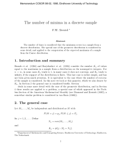


© Copyright 2026