
Forest-In Office2013
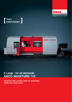
[
That’s
E[M]CONOMy:
]
Complete Solutions – unlimited Possibilities.
EMCO MAXXTURN 45
Universal machining center for the complete machining
of bar stock and chuck work
EMCO MAXXTURN 45
[ Y axis ]
- Travel +40 / –30 mm
- 90° implemented in the machine
construction
- Large distance between guide rails
stable and compact construction,
without restrictions
[ Workspace ]
- Plenty of open space
- Optimal chip flow
- Easily accessible
[ Hydraulic unit ]
- Ergonomically placed
- Automatic pressure control switching
and adjustment
- Optimal overview
[ Machine design ]
- Compact
- Requires minimal floor space
Machine with optional equipment
The EMCO MAXXTURN 45. The perfect solution for economic, off-the-shelf complete machining. Fitted with a counter spindle,
driven tools, a high-precision C axis and extremely fast rapid motion speeds, the MAXXTURN 45 gives you everything you
need for manufacturing complex turned-milled parts efficiently and at a low price. The highlight of the machine is its very stiff Y axis
with long travel – for almost unlimited machining capabilities with maximum precision. The MAXXTURN 45 comes with a choice of
Siemens or Fanuc control and with Shopturn or ManualGuide i as standard equipment.
[ Workpieces]
[ Control system ]
- Ergonomically placed
- Siemens or Fanuc
- LCD color monitor, including ShopTurn
or ManualGuide i
- Teleservice, Ethernet connection and PC
keyboard available as options
[ Shelf ]
- Retractable
- Enough space for gauges and
operating tools
[ Machine cover ]
-
Distributor
(Brass)
Camshaft
(Brass)
Eccentric disc
(Aluminium)
All-round protection against chips
100% coolant retention
Large safety glass window in door
Clear view of the workspace
Built-in buttons for operator
convenience
Push-on contact
(Steel)
[ Engineering ]
Highlights
n Very high thermostability
nExtremely machining precision
nHigh rapid motion speeds
nVery stable Y axis with long travel
nHigh-precision C axis
nDriven tools
nVery compact machine layout
nCutting-edge control technology from Siemens or Fanuc
nSimple, dialog-supported programming
nMade in the Heart of Europe
Tool head. 12-position VDI 25 radial turret with
single-motor engineering. A servo motor powers the
driven tools and the swivel movement. No tool rise.
Switches with bidirectional logic. Every station can
hold driven tool holders with a DIN 5480 coupling.
Main spindle. The main spindle with large precision bearings allows a very wide range of speeds,
combined with extremely good true running characteristics. Cooling fins are fitted to the symmetrical
headstock to ensure optimum thermal stability.
Counter spindle and parts catcher. The counter
spindle includes a parts ejector with stroke monitoring
and coolant feed . It ejects the parts automatically into
the parts catcher, which then removes them from the
machine and stores them in a bin or on an accumulating conveyor.
Tailstock. On the MAXXTURN 45 with tailstock, the
tailstock is set up on the linear roller slide and can be
automatically positioned within a range of 510 mm.
The live center is integrated into the body of the tailstock and can be removed using a pressure wedge.
Y axis. The Y axis is integrated into the basic machine structure and stands at 90° to the X axis. Extremely
short projections form the basis for solid turning and drilling operations, as well as milling operations without
interference contours.
Versions EMCO MAXXTURN 45
MT 45 MY with tailstock, Y and C axes and driven tools
MT 45 S with counter spindle
MT 45 SM with counter spindle, 2 C axes and driven tools
MT 45 SMY with counter spindle, Y axis, 2 C axes and driven tools
Power
Leistung und Momentenverlauf MT-45 Hauptspinel
P [kW]
78
18
M (S6-40%ED)
70
14
P (S6-40%ED)
60
12
50
10
40
8
30
6
20
10
1000
2000
3000
4000
5000
6000
n [rpm]
P [kW]
60
13
42
50
40
20
10
M (S6-40%)
16
8
15
30
6
10
20
4
5
4
10
2
2
0
500
0
1000
2000
3000
4000
5000
6000
n [rpm]
5
P (S6-20%ED)
M (S6-20%ED)
4
3
2
1
0
0
0
0
1000
2000
3000
4000
5000
6000
n [rpm]
Tool turret motor characteristics
Driven tools
Counter spindle characteristics
Main spindle motor characteristics
P [kW]
M [Nm]
12
P (S6-40%)
6300
500
1500
0
M [Nm]
16
2080
80
6300
90
2220
M [Nm]
Leistung und Momentenverlauf MT-45 Gegenspindel
M [Nm]
P [kW]
40
35
8
M (S6-40%ED)
7
P (S6-40%ED)
30
5
20
4
15
3
[ Main spindle ]
10
High drive
power
5
Compact,
thermostable construction
0
1000
2000
3000
4000
Large speed500range
n [rpm]
A 2-5 spindle nose
Bar capacity diameter 45 mm (1.8“)
-
2
1
6000
0
6300
5000
1666
-
[ Tool turret ]
6
25
VDI quick change system
12 driven tool stations
No alignment of the tool holder
Can be used on both spindles
Swivel speed adjustable with override
[ Counter spindle ]
[ Machine base ]
Extremely stiff welded steel fabrication
Compact structure
Very high thermostability
Filled with vibration-absorbing material
[ Machine stand ]
[ Roller guides ]
-T
hermally isolated from the
machine base
- Coolant container that is larger
and easier to clean
- 100% sealed against coolant leaks
In all linear axes
Preloaded
No backlash in any direction of force
High rapid motion speeds
No wear
Minimal lubrication
Work area
(4.3”)
0
19 (0.7”)
110
max.
WZ-L‰nge
1059 1059
(41.7”)(41.7”)
494
SW220 (8.7”)
Travel Y
40
30
75 (3”)
(1.6”)
(1.2”)
105 (4.1”)
37
”
.6
4
(1
19
(0.7”)
55
(2.2”) 24
(0.9”)
143 (5.6”)
Machine layout
720 (28.3”)
510 (20.1”)
Travel Z
105 (4.1”)
.3”
17
0(
)
44
2575 (101.4”)
2575 (101.4”)
494
(19.4”) (19.4”)
1650
)
431
1650 (65”)(17”)
(65”)
1264 (49.8”)
1264 (49.8”)
431
(17”)
1200 (47.2”)
1200 (47.2”)
”)
1562 (61.5”)
44
1562 (61.5”)
(1.7”) 49 (1.9”)
49 (1.9”)
1748 (68.8”)
445 445
1748 (68.8”)
(17.5”)(17.5”)
44
(1.7”)
(35”)
1751.5 (68.9”)
250 (9.8”)
250 (9.8”)
890
(35”)
35
(1.4”)
35
(1.4”)
531.5
1751.5890
(68.9”)(20.9”)
510 (20.1”)
670 (26.4”)
971
(38.2”)
145
(5.7”)
971
(38.2”)
KZF 173E
1025 40.4”)
122
(4.8”)
KFD-HS 160
127 (5”)
130/3
1025 40.4”)
510 (20.1”)
Travel Z2
160 (6.3”)
6 (0.3”) Travel X
6
(0.3”)
KZF 173E
127 (5”)
145 (5.7”)
6
(0.3”)
79 (3.1”)
160 (6.3”)
Travel X
max.229 (9”)
min.69 (2.7”)
21.8
(0.9”)
75
109
KFD-HS 160
79 (3.1”)
Travel X
185 (7.3”)
160 (6.3”)
25 (1
-45 (-1-8”)
-
Large speed range
C axis
Spindle clamp
A 2-4 spindle nose
531.5
(20.9”)
-
-
Individual
automation with
the EMCO
swing loader
Tailor-made solutions. For preformed blanks and parts with a
diameter larger than the spindle capacity, we offer an integrated
swing loader for fully automatic loading and part removal. This
has been designed to form a harmonious single entity with the
machine. The machine control system takes care of positioning.
A short bar loader and a 3-meter bar loader are available from
EMCO for workpieces from bar stock.
Blank feeding systems
Feed systems specific to particular blanks allow preformed workpieces to be loaded in the working spindle correctly oriented,
which enables economical unmanned operation.
Large storage capacity chain feeding system for
loading preformed blanks with the correct orientation.
Multiple infeed chutes for loading rotationally-symmetrical blanks. The length of the blanks determines
the number of infeed chutes.
Chain feeding system with V-supports for preformed
shaft parts of various shapes.
Customization:
A wide range of gripper and handling systems are available.
2-finger gripper with 180° rotary module
for loading blanks fed in vertically
2-finger toggle lever gripper for loading
shaft parts
Parallel grippers with 180° rotary module
for loading shaft parts
(1st and 2nd chucking)
[ Emco Top Load 8-42 ]
Short and to the point
In view of the ever-increasing pressure on floorspace for machines, EMCO has developed the
most compact short loader on the market: the EMCO LM800.
Finished part conveyor
The finished-part pick-up device puts the parts on an accumulating conveyor. A discontinuous belt ensures that the often very complex parts do not fall onto each other.
Unloading through the counter spindle
Long, slender workpieces can be removed from the machine through the counter spindle.
Long parts can be stowed in different ways. The finished parts can either simply roll down an
inclined surface, or be stored in a lateral magazine using a discontinuous belt.
EMCO tool break monitoring
The tool status is monitored by evaluating the load on the various axis drive motors. Excessive
loads point to wear or broken tools. Too low a load indicates a tool is missing.
Band filter with high-pressure coolant pumps
A coolant pressure of 25/40/60 or 80 bar can be set as needed. This enables coolant-fed
drilling and milling tools to be used to their best advantage.
Quality components
[Machine bases and slides]
[Tool turret]
When matching components, we
place great value on high stability,
good damping characteristics, and a
thermoneutral design. We achieve high
stability through a shorter force flow,
thermal stability through symmetry,
and dampening through the materials
and interfaces selected.
[Headstocks]
The design and manufacture of
headstocks are two of EMCO‘s core
competencies. During engineering,
the focus is on precision, robustness,
high rigidity, precise rotational characteristics, and a long service life.
Rapid-indexing turrets with adjustable
swivel speeds and milling drives represent the current state of the art. The
backlash-free milling drive is not only
ideal for milling and drilling, but also for
rigid tapping, hobbing, and polygonal
turning.
[Tool holder]
www.emco-magdeburg.de
www.emco-magdeburg.de
www.sauter-feinmechanik.com
www.wto.de
[Chip conveyor]
[Coolant pumps]
Slat band conveyors allow for flexible
implementation and the safe removal
of chips. A monitored overload clutch
prevents damage from improper use.
Low-maintenance immersion pumps
for pressures of up to 25 bar and flow
rates of up to 1500 l/min provide optimum conditions for machining and
enable reliable chip transportation.
www.knollmb.de
www.grundfos.at
Innovative, fully developed tool holder systems form the basis for costeffective machining. High changeover
accuracy and stability result in short
setup and cycle times.
[Clamping cylinder / chuck]
Hydraulically activated clamping
cylinders and chucks guarantee the
precise, safe clamping of work pieces.
Programmable sensors are used for
stroke monitoring. There is no need
for time-consuming adjustments of
contactless limit switches.
www.roehm.biz
[Hydraulic systems]
Compact dimensions, quiet operation,
and high energy efficiency - just some
of the advantages of the hydraulic
assemblies used by EMCO. Monitored
pressure switches prevent the need
for time-consuming manual pressure
adjustments.
[Ball screws and roller guides]
Highly precise and generously dimensioned guide rails and ball screws with
optimal pretensioning form the basis
for the machining of precision parts.
www.hawe.de
www.boschrexroth.com
Minimum use of resources
for maximum profit.
E[M]COLOGY
Designed for Efficiency
At EMCO, we take a consistent, responsible approach to the use of resources in machine tools in order
to safeguard long-term investments. From the development of our machines through to their construction
and manufacture, we place a strong focus on the sensible and sparing use of raw materials and energy.
This enables us to achieve parallel savings in two areas:
1. Reduction in the basic power consumption of machine tools, e.g.
assemblies are switched on and off as required and the installed
connected loads are kept to a minimum.
2. Reduction in variable consumption: This can be seen in the lighter axes,
energy recovery system, increased rate of good parts, and the shorter process chain enabled by complete
machining.
Through these measures, which are constantly being refined and further optimized, EMCO truly demonstrates that its slogan of „Designed for your Profit“ is not just an empty promise: EMCO products help save
the environment and provide intelligent customer savings without compromising on quality and flexibility.
[Regenerative drive system]
[Compact hydraulics unit with pressure accumulator]
[Roller guides]
Kinetic energy is converted into electrical energy and
fed back into the grid.
Savings of up to 10%
Thanks to its accumulator charging system, the pump
only runs when required. If the pressure accumulator is
full, the pump switches over to closed loop circulation.
Savings of up to 90%
Extremely low friction losses thanks to rolling friction.
Highly dynamic performance with minimal lubricant
consumption.
Savings of up to 50%
10
90
50
5 10 15 20 25 30 35 40 45 50 55 60 65 70 75 80 85 90 95 100%
5 10 15 20 25 30 35 40 45 50 55 60 65 70 75 80 85 90 95 100%
5 10 15 20 25 30 35 40 45 50 55 60 65 70 75 80 85 90 95 100%
[Structurally optimized mechanics]
[Highly efficient motors]
[Synchronized chip conveyor]
FEM analysis is used to optimize the relevant components in terms of their rigidity while simultaneously
reducing their weight.
Savings of up to 10%
The use of energy-efficient motors (IE2) in the coolant
preparation area guarantee highly cost-effective
operation.
Savings of up to 10%
Programmable interval times enable optimal use of
the chip conveyor independently of of the machining
process.
Savings of up to 95%
10
10
95
5 10 15 20 25 30 35 40 45 50 55 60 65 70 75 80 85 90 95 100%
5 10 15 20 25 30 35 40 45 50 55 60 65 70 75 80 85 90 95 100%
5 10 15 20 25 30 35 40 45 50 55 60 65 70 75 80 85 90 95 100%
[Intelligent standby concepts]
[Virtual machine]
[Intelligent energy management]
Reduced consumption by automatically switching off
ancillary units and machine space/screen illumination
after a defined period of inactivity on the control panel.
Savings of up to 50%
Significant reduction in the setup and running-in times
on the machine through the use of highly developed
simulation and programming software.
Savings of up to 85%
Intuitive data entry screens for activating the individual
energy-saving functions.
Savings of up to 70%
50
5 10 15 20 25 30 35 40 45 50 55 60 65 70 75 80 85 90 95 100%
85
5 10 15 20 25 30 35 40 45 50 55 60 65 70 75 80 85 90 95 100%
70
5 10 15 20 25 30 35 40 45 50 55 60 65 70 75 80 85 90 95 100%
[ Technical Data]
Emco MAXXTURN 45
430 mm (16.9“)
300 mm (11.8“)
720 mm (28.3“)
300 mm (11.8“)
480 mm (18.9“)
45 (51) mm (1.8 (2)“)
160 / 510 mm (6.3 / 20.1“)
+40 / –30 mm (+1.6 / –1.2“)
0 – 6300 (5000) rpm
78 (100) Nm (57.5 (73.7) ft/lbs)
A 2-5
80 mm (3.1“)
53 mm (2.1“)
0 – 6300 rpm
42 / 43 Nm (31 / 31.7 ft/lbs)
A 2-4
70 mm (2.6“)
0.001°
1000 rpm
0.01°
510 mm (20“)
6000 N (1350 lbs)
approx. 20 m/min (790ipm)
MT 4
13 kW (17.4 hp)
10 / 7. 5 kW (13.41 / 10.1 hp)
12
VDI 25
Tool turret
Tool cross-section for square tools
Shaft diameter for boring bars
Turret indexing time
Driven tools Speed range
Maximum torque
Maximum drive power
Number of driven tools
Feed drives
Rapid motion speed X / Y / Z
Feed force in the X / Y axes
Feed force in the Z axis
Acceleration time from 0 to rapid X / Z
Positioning scatter Ps VDI 3441 in X / Y/ Z
Coolant system
Tank volume
Pump power standard
Pump capacity at 3,5 bar / 1 bar
Pump capacity at 10 bar / 5 bar (optional)
Power consumption
Connected load
Compressed air
Dimensions
Height of spindle center above floor
Total machine height
Foot print (without chip conveyor) L x D Total weight
Safety devices
16 x 16 mm (0.6 x 0.6“)
25 mm (1”)
0.2 sec
0 – 6000 rpm
16 Nm (11.8 ft/lbs)
4 kW (5.4 hp)
12
24 / 10 / 30 m/min (944.9 / 393.7 / 1181.1 ipm)
4000 / 4000 N (899.2 / 899.2 lbs)
6000 N (1345 lbs)
0.1 sec
3 / 3 / 3 µm (0.0001 / 0.0001 / 0.0001“)
250 liters (66.1 gal)
0.57 (2.2) kW
(0.76 (2.95) hp)
15 / 65 l/min
(3.9 / 17.2 gal/min)
5 / 50 l/min (1.3 / 13.2 gal/min)
25 kVA
6 bar (87 PSI)
1100 mm (43.3“)
1958 mm (77”)
2575 x 1790 mm
(102“ x 70“)
4000 kg (8818.4 lb)
CE conform
www.emco-world.com
EMCO MAIER Ges.m.b.H.
Salzburger Str. 80 . 5400 Hallein-Taxach . Austria
Phone +43 6245 891-0 . Fax +43 6245 86965 . [email protected]
EN4560 . 01/13 . Subject to change due to technical progress. Errors and omissions excepted.
Work area
Swing over bed Swing over cross slide Main spindle / counter spindle distance
Max. turning diameter Maximum part length
Maximum bar diameter (optional)
Travel
Travel in X / Z Travel in Y
Main spindle Speed range
Torque at spindle (optional)
Spindle nose DIN 55026
Spindle bearing (inner diameter at front)
Spindle bore hole
Counter spindle
Speed range
Torque at spindle (Siemens / Fanuc)
Spindle nose DIN 55026
Spindle bearing (inner diameter at front)
C axis
Resolution Rapid motion speed
Spindle indexing (disc brake)
Tailstock
Tailstock travel
Maximum thrust
Maximum travel speed
Tailstock bore taper
Drive power
Main spindle
Counter spindle (Siemens / Fanuc)
Tool turret
Number of tool positions VDI shaft (DIN 69880)


© Copyright 2026