
Generalforsamling i HK-klubben mandag den 19. januar 2015
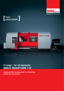
[
E[M]CONOMY
means:
]
Outstanding Performances, again and again.
HYPERTURN 665
High-performance turning/milling center with Y and B axes for complete machining of complex workpieces in one operation
HYPERTURN 665
[ Upper tool turret ]
-
[ Main spindle ]
12-station tool turret
VDI30 (VDI40) quick-change system
12 driven tool positions
Servo-controlled
Rigid tapping
Polygonal turning, etc.
- Integrated spindle motor (ISM) in
synchronous technology – water-cooled
- High drive power
- High torque
- Wide speed range
- Highly dynamic
- Bar capacity ø 65 mm (76,2)
[ Control ]
-
Ergonomically placed
90° pivot
Siemens Sinumerik 840D-sl
LCD color monitor
[ Lower tool turret ]
-
12-station tool turret
VDI30 (VDI40) quick-change system
12 driven tool stations
Servo-controlled
Rigid tapping
Polygonal turning, etc.
Machine with optional equipment
The new HYPERTURN Series 3. A brilliant fusion of state-of-the art turning and milling technology – for highly productive, complete
machining in a new dimension. The aim: to increase productivity when machining complex workpieces. The equipment: stateof-the-art, extremely dynamic, water-cooled spindle motors, with Y and B axes and the latest control and drive technology.
[ Workpieces ]
[ Y axis ]
-
Travel +/- 50 mm
Stable, compact construction
Wide guide clearances
Tapered carriage system
Sprocket-wheel
(Steel Ck45)
[ Counter spindle ]
- Integrated spindle motor (ISM) in
synchronous technology – water-cooled
- High drive power
- High torque
- Wide speed range (max. 7000 rpm)
[ Chip conveyor ]
-
Hinged type conveyor
Ejection height 1200 mm
Integrated coolant tank 300 l
Turret pumps: 2 x 14 bar
Flushing pumps: 2 x 3.7 bar
Bonnet flange
(Brass)
Sensor housing
(Stainless steel)
[ Work area ]
-
Generous design
Straight chip fall
Optimum accessibility
Guideways 100 % covered
[ Finished part container ]
- Easy access
- Universal
- Extendable with finished part
conveyor as an option
Knee
(Steel 16Mn Cr 5))
I.D. roller burnishing
Undercut
Form E/F
Tapping
O.D. roller burnishing
Face and O.D. turning
I.D. deburring
I.D. gear/slot shaping
I.D. turning
Drilling
Reaming
Milling slant slots
Turn-milling of eccentrical
diameter
Knurling
Hyper-Flexibility
Machine flexibility is often sacrificed for the sake of productivity. Not with the HYPERTURN:
with its high-performance and exceptionally mobile milling spindle and an almost inexhaustible
tool magazine, the HYPERTURN can do nearly anything - and very quickly.
Gear machining
(gear hobbing)
Thread milling
Circular spitgot milling
Slot milling
Deep-hole drilling
Wobble broaching
HEXAGON
I.D. threading
I.D. boring
I.D. undercutting
I.D. grooving
Engraving
Contour milling (elliptical)
Hole patterns centering,
drilling, tapping
Multifunctional workpiece
[Engineering ]
Highlights
Q High dynamics due to state-of-the-art spindle
motor technology
Q All spindles liquid-cooled for optimum thermostability
Q High productivity due to short tool change times
Q Both tool turrets can be used on both spindles
Q Hydropol bed design for maximum stability and
oscillation damping
Q Excellent repeatability due to linear guides
Q Short set-up times due to ease of access to work area
Pivoting control unit. The Sinumerik 840D SolutionLine
control is on the left of the machine on the HYPERTURN
Series 3 and pivotable. This enables ergonomic operation
of the machine and shortens setup times. Most modern
machining cycles supported with animated graphics, 3D
simulation of the machining process and Ethernet connectivity simplify the programming and the daily operation
of the machine.
Part pick-up device. To ensure the gentle removal of
finished parts, the HYPERTURN 665 is fitted with a part
pick-up device as standard equipment. The finished parts
are deposited in the standard parts holder or on an optional
backup conveyor.
NC tailstock. The HYPERTURN with this tailstock version
is particularly suitable for machining shaft parts in large
batches. The tailstock is completely NC controlled and can
be positioned using a recirculating ball spindle. This also
enables interpolation with other axes, saving machining
time.
The machine design. Finite element analysis has been
used to optimize the machine components for static and
dynamic rigidity. The core element here is the machine
base made of HYDROPOL®, a composite material consisting of special concrete and steel which offers far-reaching
advantages over conventional materials. The results are
improved surface finish, closer manufacturing tolerances
and longer tool life.
Integrated spindle motor (ISM). The latest synchronous technology guarantees the highest dynamics and
exceptional torque in a compact design. Liquid cooling in
conjunction with automatic temperature control maintains a
constant temperature for all spindle motors.
High-precision Y axis. The HYPERTURN’s Y axis is designed
to divide the cutting forces over two guide planes. The result
is outstanding rigidity for all turning and milling operations.
The +/– 50 mm travel permits off-center milling and drilling.
HSK-Multi-tool
HYPERTURN PowerMill. In this design, the upper turret
is replaced by a 14.5 kW milling spindle and direct drive
(hollow-shaft motor). The B axis travels 210°. And the
tool carrier is a 24-station tool magazine with HSK-T63 or
CAPTO C4 holders (48 tool stations optional). These features
make this machine the perfect balance of turning and milling technology. Its great flexibility and high metal-cutting
performance makes it especially suitable for complete
machining of complex workpieces with high milling content.
24-tool station magazine. HSK-T63 or CAPTO C4 (48 tool
stations optional) for tool management. Easy access for
inspection and manual magazine loading. Integrated into
the machine casing for excellent space-saving.
CAPTO Multikopf
HSK-Multi-tool. Triple slot toolholder for standard tools.
Ensures shorter downtimes and more flexibility.
CAPTO Multihead. A tool for roughing, finishing, threading, grooving and milling. Saves tool changing time frees
up space in the tool magazine.
HYPERTURN PowerMill with powerful milling spindle and 24-slot tool magazin within the basic version. A 12 station tool turret with up to 12 driven tools can be implemented
below the spindle centre line. This allows to machine simultaneously on both main and counter spindles.
EMCO HYPERTURN 665 versions
HT 665 is the basic version with main and counter spindles, two tool turrets
with or without driven tool stations
HT665 with Y axis in upper slide system
HT665 with Y and B axes as milling spindle (PowerMill) with
tool magazine
HT 665 with Y and B axes as milling spindle, without lower tool turret;
for complete machining of small batch sizes
The Esprit CAM system offers high flexibility and process security, a comprehensive selection of machining cycles, maximum tool control, and cross-machine technology for your
entire production facility.
[CAD]
Direct CAD data import
- AutoCAD (DWG)
- Parasolid®
- Solid Edge ®
- Solid Works ®
- ACIS® (SAT)
- Optional interfaces: CATIA®,
Pro/ENGINEER®, STEP, STL,...
[CAD]
[CAM]
-
2-22 axis turning
2-5 axis milling
Multi-tasking of turning and milling
3D machine space simulation
Certified post-processors
The Virtual Machine
A 1:1 mapping of the real machine for defining and testing processes, optimizing machining
sequences, and training new operators.
[Process chain]
[CPS]
-
1:1 simulation with collision detection
Direct connection to CAM ESPRIT
Process optimization
Reverse simulation of existing NC codes
Reduction in scrap rates
Training on the virtual machine
Simulation of loading systems
(e.g. EMCO gantry loader)
[CAM] [CPS] [Production]
[Production]
- Reduction in set-up costs
- Reduction in downtimes
- Reduction in repair costs
OPTIMUM MACHINE UTILIZATION
Automatic
Return
on Investment
Even in the design stage of the HYPERTURN, the EMCO development
engineers were already aware that a highly productive industrial machine
such as the EMCO HYPERTURN would need high-performance automation
periphery. Which is why the HYPERTURN gantry loader was immediately
included in the HYPERTURN concept and design, which produced a
particularly homogenous solution.
Workpiece magazine
Blank-specific pallet attachments enable oriented loading of blanks into the machine and increase the parts stock for
unmanned production. Changeover times are reduced or eliminated thanks to the perfect adjustment to the customer‘s parts.
4-station pallet attachment for tees
6-station pallet attachment for articulated brackets
4-station pallet attachment for valve caps
20-station pallet magazine with customer-specific pallets
Multi-pallet attachment for a family of parts
Customizing options:
The HYPERTURN gantry loader is a universal loading and unloading device for all models in the HYPERTURN Series. EMCO
Automation can equip it to your individual needs with numerous gripper and handling systems. How we do it: we standardize
the components and customize the solution. The goal: a custom-tailored machine for the same price as a standard unit.
2x3-jaw double gripper head
4x3-jaw gripper head
Shaft gripper head
Pivoting B axis
The special feature of the HYPERTURN gantry loader is the integrated B axis as swivel unit.
It enables blanks to be loaded into devices at an angle and simultaneous pivoting and
positioning. This means not only almost unlimited flexibility in loading and unloading, it also
dramatically reduces cycle times.
Measuring system
An integrated measuring unit allows serial production of high precision components with minimum man-power. Tool offset changes are done fully automatically. Each workpiece is loaded
into the measuring system via the gantry loader and measured using the feeler. Good parts
are pushed into the storage box and bad parts are separated into a special chute.
Short and to the point
In view of the ever-increasing pressure on floorspace for machines, EMCO has developed
the most compact short loader on the market: the EMCO LM1200. Custom-made for the
HYPERTURN – and the perfect solution for automatic feeding and loading of cut-to-length
bars.
EMCO TOP LOAD
A bar-loader which automatically reloads 3-meter bar stock. The loader is exceptionally
reliable and has a patented guidance system that allows you to switch to a different bar
stock diameter in just a minute or two. If required, the loader can also be extended by
adding several material storage strips and can therefore be operated automatically for
even longer periods.
Unloading through the counter spindle
Long, thin workpieces can be removed from the machine using the counter spindle. Long
parts can be stored in different ways. Finished parts can simply be allowed to roll away via
a sloping surface or can be gathered to the side for storage using a timed belt.
[ Options ]
Individualize your HYPERTURN with our wide range of
options. Amongst others, with a steady rest fitted to the
lower turret to support long, thin workpieces. This can
be swung in as required instead of metal-cutting tools. A
live centre can also be included to support shaft parts in
one turret position.
Tool eye
The tool measurement sensor mounted in the working area of the HYPERTURN makes it
possible to measure tools in both the upper and lower turret within the machine
Finished part conveyor
The finished-part pick-up device places the parts on an accumulating conveyor. The
conveyor is timed to prevent the parts, some of which are very complex, from falling on
top of each other.
EMCO tool monitoring system
The tool status is monitored by evaluating the load on the various axis drive motors. Excessive
loads point to tool wear or breakage. Too low a load indicates a tool is missing.
Band filter system with high-pressure coolant pumps
A coolant pressure of 25/40/60/80 bar can be set as needed. This enables coolant-fed
drilling and milling tools to be used to their best advantage.
Rotary window
The ingenious rotating glass disc provides a perfect view into the work area of the machine.
So the machining can be observed even when the coolant system is switched on.
Power and torque diagram
M (Nm)
P (kW)
300
M (Nm)
30
P (S6-40 % D.C.)
P (kW)
150
25
P (S6-40 % D.C.)
250
25
200
20
P (S1-100 % D.C.)
P (S1-100 % D.C.)
200
20
150
15
100
10
15
100
10
50
M (S6-40 % D.C.)
50
150
M (S6-40 % D.C.)
5
M (S1-100 % D.C.)
5
M (S1-100 % D.C.)
0
0
0
1000
2000
3000
4000
5000
0
0
0
1000
2000
3000
HYPERTURN 665 main spindle
HYPERTURN 665 counter spindle
HYPERTURN 665 with bar loader LM1200
6524 (256.85”)
4789 (188.5”)
1503 (59.2”)
240
(9.4”)
4103 (161.5”)
2168 (85.4”)
(18.3”) Lag – Bolt hole distances to secure the machine to the floor.
1200 (47.2”)
442
(17.4”)
1027 (40.4”)
2531 (99.6”)
Lag – Bolt hole distances to
secure the machine to the floor.
826
(32.5”)
915,5
(36”)
4170 (164.2”)
870
(34.25”)
595
(23.4”)
1045 (41.1”)
2264 (89.1”)
1588 (62.5”)
1080 (42.5”)
3376 (132.9”)
50
(2”)
5000
6000
7000
n (rpm)
6000
n (rpm)
465
4000
1705 (67.1”)
Work area layout and turret clearance
HYPERTURN 665 with Y axis
Power and torque diagram
M [Nm]
M [Nm]
P [kW]
P [kW]
15
14
PS6
M (S6-25%D.C.)
25
13
6,7
12
6
11
PS1
20
10
5
9
40
8
MS6
15
4
7
30
6
3
10
5
20
4
MS1
2
0
0
2
P (S6-25%D.C.)
3
10
5
1
0
1000
2000
3000
3500
1
4000
5000
6000
S1=100%
S6=40% (bei 1 min. ED)
HYPERTURN 665 PowerMill milling spindle
7000
8000
0
0
9000 10000
0
-1]
[rpm]
nn[min
1000
2000
3000
4000
5000
n [rpm]
Tool changer driven tools
Work area layout and turret clearance HYPERTURN 665 with tailstock
Work area layout and turret clearance 665 PowerMill
[ Technical data]
Work area
Swing over bed
Swing over slide
Distance between spindle noses
Max. turning diameter
Max. part length
Max. bar-stock diameter
Travel
Travel in X/X2
Travel in Z/Z2/Z3
Travel in Y
Main spindle
Speed range (infinitely variable)
Maximum torque
Spindle nose DIN 55026
Spindle diameter at front bearing
Spindle bore (excluding draw pipe)
Counter spindle
Speed range (infinitely variable)
Maximum torque
Spindle nose DIN 55026
Spindle diameter at front bearing
C axes
Resolution
Rapid traverse
Drive power
Main spindle (AC hollow-spindle motor)
Counter spindle (AC hollow-spindle motor)
Tool turret top and bottom
Number of tool stations
VDI shaft (DIN 69880)
Tool cross-section for square tools
Shank diameter for boring bars
Turret indexing time
Driven tools
Speed range
Max. torque
Drive power
Number of driven tools
Tailstock
Tailstock travel
Tailstock thrust
Inside taper for live centre
Max. traveling speed
B-PowerMill (with milling spindle)
Travel range (with interpolation)
Holding torque of indexing (5°)/positioning (0.001°)
Number of tools
Tool holder
Maximum torque
Drive power
Speed range
Tool changing time (tool to tool)
Feed drives
Rapid motion speed in X/Z/Y/Z3 (counter spindle)
Feed force in X/Z/Z3 (counter spindle)
Coolant system
Tank capacity
Pump power
Power consumption
Connected load
Compressed air
Dimensions
Height of center above floor
Total height
Footprint (excluding chip conveyor) W x B
Total weight
Safety devices
600 mm (23.6“)
500 mm (19.7“)
975 mm (38.4“)
430 mm (16.6“)
744 mm (29.3“)
65 (76,2) mm (2.6“ (3“))
280 / 205 mm (11 / 8.1“)
900 / 750 / 750 mm (35.4 / 29.5 / 29.5“)
100 (+/–50) mm (3.9 ( +/–2)“)
0 – 5000 (4000) rpm
250 Nm (184.3 ft/lbs)
A2-6 (A2-8)
105 (130) mm (4.1“ (5.1“))
Ø 73 (86) mm (2.9“ (3.4“))
0 – 7000 rpm
130 Nm (95.8 ft/lbs)
A2-6
Ø 73 (86) mm (2.9“ (3.4“))
0,001°
1000 rpm
29 kW (38.9 hp)
22 kW (29.5 hp)
2x12
30 (40) mm (1.2“ (1.6“))
20 x 20 (25 x 25) mm (0.8 x 0.8“ (1 x 1“))
32 mm (1.3“)
0,2 sec
0 – 5000 (4500) rpm
25 Nm (18.4 ft/lbs)
6,7 kW (9 hp)
2 x 12
750 mm (29.5”)
1000-10000N (224-2240 lb)
MT4
15 m/min (590ipm)
210°
3600 / 1300 Nm (2 653/958 ft/lbs)
24 / 48
HSK-T63 (Capto C4)
40 Nm (29.5 ft/lbs)
14,5 kW (19.4 hp)
0 – 10000 rpm
1,3 sec
24 / 30 / 10 / 30 m/min (945 / 1 181 / 394 / 1 181 ipm)
5000/8000/9000 N (1 124/1 798/2 023 lbs)
300 l (79 gal)
2 x 2.2 kW (2.7 x 3 hp)
46 kVA
6 bar (87 PSI)
1200 mm (47.2“)
2300 mm (90.6“)
3400 x 2550 (133.9 x 100.4”)
approx. 9500 kg (15 432 lb)
to CE
Quality components
[Machine bases and slides]
[Tool turret]
When matching components, we
place great value on high stability,
good damping characteristics, and a
thermoneutral design. We achieve high
stability through a shorter force flow,
thermal stability through symmetry,
and dampening through the materials
and interfaces selected.
[Headstocks]
The design and manufacture of
headstocks are two of EMCO‘s core
competencies. During engineering,
the focus is on precision, robustness,
high rigidity, precise rotational characteristics, and a long service life.
Rapid-indexing turrets with adjustable
swivel speeds and milling drives represent the current state of the art. The
backlash-free milling drive is not only
ideal for milling and drilling, but also for
rigid tapping, hobbing, and polygonal
turning.
[Tool holder]
www.emco-magdeburg.de
www.emco-magdeburg.de
www.sauter-feinmechanik.com
www.wto.de
[Chip conveyor]
[Coolant pumps]
Slat band conveyors allow for flexible
implementation and the safe removal
of chips. A monitored overload clutch
prevents damage from improper use.
Low-maintenance immersion pumps
for pressures of up to 25 bar and flow
rates of up to 1500 l/min provide optimum conditions for machining and
enable reliable chip transportation.
www.knollmb.de
www.grundfos.at
Innovative, fully developed tool holder systems form the basis for costeffective machining. High changeover
accuracy and stability result in short
setup and cycle times.
[Clamping cylinder / chuck]
Hydraulically activated clamping
cylinders and chucks guarantee the
precise, safe clamping of work pieces.
Programmable sensors are used for
stroke monitoring. There is no need
for time-consuming adjustments of
contactless limit switches.
www.roehm.biz
[Hydraulic systems]
Compact dimensions, quiet operation,
and high energy efficiency - just some
of the advantages of the hydraulic
assemblies used by EMCO. Monitored
pressure switches prevent the need
for time-consuming manual pressure
adjustments.
[Ball screws and roller guides]
Highly precise and generously dimensioned guide rails and ball screws with
optimal pretensioning form the basis
for the machining of precision parts.
www.hawe.de
www.boschrexroth.com
Minimum use of resources
for maximum profit.
E[M]C
COLOGY
OLOG
Designed for Efficiency
At EMCO, we take a consistent, responsible approach to the use of resources in machine tools in order
to safeguard long-term investments. From the development of our machines through to their construction
and manufacture, we place a strong focus on the sensible and sparing use of raw materials and energy.
This enables us to achieve parallel savings in two areas:
1. Reduction in the basic power consumption of machine tools, e.g.
assemblies are switched on and off as required and the installed
connected loads are kept to a minimum.
2. Reduction in variable consumption: This can be seen in the lighter axes,
energy recovery system, increased rate of good parts, and the shorter process chain enabled by complete
machining.
Through these measures, which are constantly being refined and further optimized, EMCO truly demonstrates that its slogan of „Designed for your Profit“ is not just an empty promise: EMCO products help save
the environment and provide intelligent customer savings without compromising on quality and flexibility.
[Regenerative drive system]
[Compact hydraulics unit with pressure accumulator]
[Roller guides]
Kinetic energy is converted into electrical energy and
fed back into the grid.
Savings of up to 10%
Thanks to its accumulator charging system, the pump
only runs when required. If the pressure accumulator is
full, the pump switches over to closed loop circulation.
Savings of up to 90%
Extremely low friction losses thanks to rolling friction.
Highly dynamic performance with minimal lubricant
consumption.
Savings of up to 50%
10
0
90
0
50
0
5 10
0 15 20 25 30 35 40 45
5 50
0 55 60 65 70 75 80 85 90 95 100%
5 10
0 15
5 20 25 30 35
5 40 45
5 50
0 55 60 65 70 75 80 85
5 90
09
95 100%
5 10
0 15
5 20 25 30 35
5 40 45
5 50
0 55
5 60 65 70 75 80 85 90 95 100%
[Structurally optimized mechanics]
[Highly efficient motors]
[Synchronized chip conveyor]
FEM analysis is used to optimize the relevant components in terms of their rigidity while simultaneously
reducing their weight.
Savings of up to 10%
The use of energy-efficient motors (IE2) in the coolant
preparation area guarantee highly cost-effective
operation.
Savings of up to 10%
Programmable interval times enable optimal use of
the chip conveyor independently of of the machining
process.
Savings of up to 95%
10
0
10
0
95
5
5 10
0 15 20 25 30 35 40 45
5 50
0 55 60 65 70 75 80 85 90 95 100%
5 10
01
15
5 20 25 30 35 40 45
5 50 55 60 65 70 75 80 85 90 95 100%
5 10
0 15
5 20 25 30 35
5 40 45
5 50
0 55 60 65 70 75 80 85 90
0 95
51
100%
[Intelligent standby concepts]
[Virtual machine]
[Intelligent energy management]
Reduced consumption by automatically switching off
ancillary units and machine space/screen illumination
after a defined period of inactivity on the control panel.
Savings of up to 50%
Significant reduction in the setup and running-in times
on the machine through the use of highly developed
simulation and programming software.
Savings of up to 85%
Intuitive data entry screens for activating the individual
energy-saving functions.
Savings of up to 70%
50
0
5 10
0 15
5 20 25 30 35 40 45
5 50
05
55 60 65 70 75 80 85 90 95 100%
85
5
5 10
0 15
5 20 25 30 35 40 45
5 50 55 60 65 70 75 80 85
85 9
90 95 100%
70
0
5 10
0 15
5 20 25 30 35
5 40 45
5 50
0 55 60 65 70 75 80 85 90
0 95
51
100%
EN4350 . 08/12 . Subject to change due to technical progress. Errors and omissions excepted.
www.emco-world.com
EMCO MAIER Ges.m.b.H.
Salzburger Str. 80 . 5400 Hallein-Taxach . Austria
Phone +43 6245 891-0 . Fax +43 6245 86965 . [email protected]


© Copyright 2026