
code issues Motor Design Letters and By James Stallcup Sr., NEC/OSHA Consultant
codeissues
By James Stallcup Sr., NEC/OSHA Consultant
Motor Design Letters and
Code Letters – How They
Are Utilized
Motor circuits must be designed to provide protection
for motor windings and components when motors are
starting, running, and driving loads. Motor windings are
protected by overcurrent protection devices that are
selected according to the type used, based upon the
amount of starting current required. Overcurrent protection devices are sized by percentages based on the
type motor, starting method, and design or code letter.
Starting methods should be selected based on the
amount of current required to start and run the motor
or the amount that is reduced by utilizing a particular
starting method.
This article, one of a series, will address a variety of
motors and their many different characteristics and why it
is sometimes desirable to choose one over the other, based
on the requirements of the driven load or equipment.
Types Of Motors
Table 430.52
The following are five types of motors that must be
considered when sizing OCPDs to allow motors to start
and run:
(1) Single-phase AC squirrel-cage,
(2) Three-phase AC squirrel-cage,
(3) Wound-rotor,
(4) Synchronous,
(5) DC.
run winding and the other is the starting winding. A
motor with this additional starting winding on the stator is called a split-phase, single-phase, induction motor;
it provides the ability to both start and run. The starting
winding has a higher resistance than the running winding, which creates a phase displacement between the
two. It is this phase displacement between the two
windings that gives split-phase motors the power to
start and run.
The angular phase displacement is about 18 to 30
degrees, which provides enough starting torque (twist or
force) to start the motor. The motor operates on the
running winding after the rotor starts and has reached a
speed of about 75 to 80 percent of the motor's synchronous speed. The starting winding is then disconnected
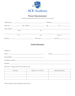
by a centrifugal switch. (See Figure 1)
POWER SUPPLY
WINDING
• RUNNING
WINDING
• STARTING
SWITCH
• CENTRIFUGAL
POWER SOURCE
• 1Ø
• 120 VOLT, OR
• 240 VOLT
NEC TABLE 430.52
Figure 1. The above illustrates an example of a single-phase squirrel-cage motor listed in Table 430.52 of the NEC.
Figure 1
Single-Phase Squirrel-Cage Motors
Squirrel-cage motors are how induction motors are
known in the electrical industry. An induction motor
operates on the same principles as the primary and secondary windings of a transformer. When power energizes the field windings they serve as the “transformer”
primary by inducing voltage into the rotor, which serves
as the secondary. Squirrel-cage motors have two windings on the stator (the stationary windings): one is the
26 >> necdigest winter 2004 necdigest.org
Three-Phase Squirrel-Cage Motors
Three-phase squirrel-cage motors have three separate
windings per pole on the stator, which generate magnetic fields that are 120 degrees out-of-phase with each
other. Three-phase motors do not require an additional
starting winding. A three-phase induction motor will
always have a peak phase of current. This is due to the
codeissues
alternating current reversing its direction of flow. In
other words, when alternating current of one phase
reverses its direction of flow, a peak current will be
developed and as current reverses direction again, a second phase will peak, etc. Three-phase motors provide a
smooth and continuous source of power once they are
started and driving the load. (See Figure 2)
480 V POWER SUPPLY
CONDUCTORS
• 430.22(A)
CONTROLLER
• 430.81
SECONDARY
CONDUCTORS
• 430.23(A)
DRUM
CONTROLLER
DISCONNECTING
MEANS
• 430.102
RESISTOR BANK
• 430.23(C)
POWER
SOURCE
• 3Ø
NOTE: THE MOTORS BELOW CAN BE
EITHER NEMA DESIGN B, C, OR D.
DISCONNECTING
MEANS
RESISTOR BANK CONDUCTORS
USED AT CONTINUOUS DUTY
• 430.23(B)
WINDINGS
• 3Ø
• WYE MOTOR
NEC TABLE 430.52
Figure 3. The above illustrates an example of a three-phase wound motor listed in Table 430.52 of the NEC.
Figure 3
SUPPLY
WINDINGS
• 3Ø
• DELTA MOTOR
NEC TABLE 430.52
Figure 2. The above illustrates an example of a three-phase squirrel-cage motor listed in Table 430.52 of the NEC.
Figure 2
Three-phase induction motors are wound-rotor
motors, and are similar in design to squirrel-cage induction motors. They are three-phase motors having two
sets of leads. One set consists of the main leads to the
stator – the field poles – and the other set consists of the
secondary leads to the rotor. The secondary leads are
connected to the rotor through slip rings, while the
other end of the leads are connected to a controller and
a bank of resistors. The speed of the motor varies with
the amount of resistance added in the motor circuit. The
rotor will turn slower when the resistance in the rotor
circuit is greater, and vice versa. The resistance may be
incorporated in the controller or as a separate resistor
bank. (See Figure 3)
Synchronous Motors
The following are two types of synchronous motors that
are available:
(1) Non-excited, and
(2) Direct-current excited.
Synchronous motors are available in a wide range of
sizes and types that are designed to run at fixed speeds.
A DC source is required to excite a direct-current excited
synchronous motor. The torque required to turn the
rotor for a synchronous motor is produced when the DC
current of the rotor field locks in with the magnetic field
of the stator's AC current. (See Figure 4)
POWER SOURCE
• ALTERNATING CURRENT
MOTOR
• 3Ø
• SYNCHRONOUS
POWER SOURCE
• DIRECT CURRENT
ROTOR
NEC TABLE 430.52
Figure 4. The above illustrates an example of a three-phase synchronous motor listed in Table 430.52 of the NEC.
Figure 4
necdigest.org winter 2004 necdigest << 27
codeissues
DC Motors
Direct-current only is used to operate DC motors. A DC
motor is designed with the following two main parts:
(1) The stator, and
(2) The rotor (or armature).
The stationary frame of the motor is called the stator.
The armature, mounted on the drive shaft, is known as the
rotor. The speed of a DC motor with a given load is determined by the amount of current driven through the rotor.
(See Figure 5)
DYNAMIC BRAKING
RESISTORS
DC POWER SUPPLY
SEPARATELY
MOUNTED
SERIES MOTOR
• 300% TO 375% FULL-LOAD
TORQUE IS PROVIDED
SERIES
FIELD
ARMATURE
MOTOR
CONTROLLER
Figure 6. A series DC motor provides a very high starting torque of 300 percent to 375 percent of the full-load torque.
Figure 6
SERIES
FIELD
TERMINAL
BOARDS
+
SERIES DC MOTOR
POWER
RESISTORS
CB
• 2-POLE
TO POWER
SUPPLY
SHUNT MOTOR
• 125% TO 200% FULL-LOAD
TORQUE IS PRODUCED
DC MOTOR
NEC 430.29
TABLE 430.29
SHUNT
FIELD
ARMATURE
TO POWER
SUPPLY
+
Figure 5. The above illustrates an example of a DC motor listed in Table 430.52 of the NEC.
Figure 5
Shunt DC Motors
A starting torque of 125 to 200 percent of the full-load
torque is provided when using shunt DC motors. Loads
that are required to be driven with constant or adjustable
speeds, but do not require high starting torque, use this
type of motor. Shunt DC motors are useful for applications such as woodworking machines, printing presses,
and papermaking machines. (See Figure 7)
28 >> necdigest winter 2004 necdigest.org
Figure 7. A shunt DC motor provides a medium starting torque of 125 percent to 200 percent of the full-load torque.
Figure 7
SERIES
FIELD
SHUNT
FIELD
MOTOR
• 180% TO 260% FULL-LOAD
TORQUE IS PROVIDED
TO POWER
SUPPLY
ARMATURE
+
COMPOUND DC MOTOR
Figure 8. A compound DC motor provides a high torque of 180 percent to 260 percent of the full-load torque.
Figure 8
ILLUSTRATIONS COURTESY OF GRAYBOY, INC.
Series DC Motors
A very high starting torque of 300 to 375 percent of the
full-load torque is provided when using series DC
motors. Loads that are required to be driven with high
torque and poorly regulated speed use this type of
motor. The speed varies depending on the mechanical
load. Series DC motors are used in installations such as
traction work, where the speed varies depending on the
load on the hoist. The armature and fields are connected
in series. (See Figure 6)
SHUNT DC MOTOR
codeissues
Compound DC Motors
Compound DC motors provide a starting torque of
180 to 260 percent of the full-load torque and a constant speed. The compound DC motor is equipped with
a series and a shunt winding. The series winding is connected in series with the armature and the shunt winding
is connected in parallel with the armature. This type of
motor has the characteristics of both series and shunt
motors during operation. Loads such as crushers, reciprocating compressors, and punch presses use compound
DC motors. (See Figure 8)
Calculating Torque
To accelerate and drive a piece of equipment, the motor
must be capable of producing a torque. Torque is the
turning or twisting force of the motor and is measured
in foot-pounds or pound-feet.
Full-Load Torque
The full-load torque of a motor is determined by
multiplying the horsepower by 5252, and then dividing
by the rpm of the motor.
Motor Tip: The value of 5252 is found by dividing
33,000 foot-pounds per minute by 6.2831853
(33,000 ÷ 6.2831853 = 5,252).
{6.2831853=2 x π; π=3.14159265 } (See Figure 9)
Starting Torque
The starting torque of a motor varies with the
classification of the motor. Motors are classified by
NEMA as Design B, C, or D. These standardized types
are the most used motors in the electrical industry.
Other types of motors classified by NEMA are Design F
or G motors.
Each class of motors has a different rotor design,
which provides a different value of starting torque.
Different values of torque, speed, current, and slip for
starting and driving the various types of loads are
produced when using NEMA Design B, C, or D motors.
The Design type of the motor to be selected depends on
the starting torque and running torque required to drive
the load. (See Figure 13)
Class B Motors
The most used motor in the electrical industry is
Class B. For example, the starting torque of an
induction motor will increase by 150 percent of the fullload torque when using Class B design motors. Most
designers however, assume a starting torque of less than
150 percent when using Class B induction motors to
start and run loads. (See Figure 10)
Class C Motors
The starting torque of a squirrel-cage induction motor
will increase about 225 percent of the full-load torque
when using Class C design motors. However, to keep
from overloading the starting torque, designers will
often load these motors to less than 225 percent.
For example: What is the full-load torque and starting
torque of a 40 HP, Class C design induction motor
operating at 1725 rpm?
Figure 9
Step 1:
Finding full-load torque
Torque = HP x 5252 ÷ rpm
Torque = 40 x 5252 ÷ 1725
Torque = 210,080 ÷ 1725
Torque = 121.8 ft. lbs.
Step 2:
Finding starting torque
Full-load torque increased by 225%
Torque = 121.8 ft. lbs. x 225%
Torque = 274.05 ft. lbs.
necdigest.org winter 2004 necdigest << 29
codeissues
Solution: The full-load torque is 152.2 ft. lbs. and the
starting torque is 418.6 ft. lbs.
Energy Efficient Motors
When designing and installing an energy efficient motor, it
is most important to know the starting and running torque
of the load. The difference between the nominal and the
minimum efficiency must also be determined in order for
the motor to be properly sized to start and drive the load.
Solution: The full-load torque is 122 ft. lbs. and the
starting torque is 274 ft. lbs.
Class D Motors
The starting torque of a squirrel-cage induction motor
is increased about 275 percent of the full-load torque
when using Class D design motors. However, to keep
from overloading the starting torque of a motor, designers will often load these motors to less than 275 percent.
For example: What is the full-load torque and starting
torque of a 50 HP, Class D design induction motor
operating at 1725 rpm?
Step 1:
Finding full-load torque
Torque = HP x 5252 ÷ rpm
Torque = 50 x 5252 ÷ 1725
Torque = 262,600 ÷ 1725
Torque = 152.2 ft. lbs.
Step 2:
Finding starting torque
Full-load current increased by 275%
Torque = 152.2 ft. lbs. x 275%
Torque = 418.6 ft. lbs.
30 >> necdigest winter 2004 necdigest.org
Two-Speed Motors
The full-load torque of a motor is determined by its rpm.
A motor turning at 1800 rpm produces less torque than a
motor turning at 1200 rpm.
For example: What is the full-load torque for a two-speed
30 HP motor, operating at either 1200 rpm or 1800 rpm?
Step 1:
Finding full-load torque (1200)
Torque = HP x 5252 ÷ rpm
Torque = 30 x 5252 ÷ 1200
Torque = 157,560 ÷ 1200
Torque = 131.3 ft. lbs.
Step 2:
Finding full-load torque (1800)
Torque = HP x 5252 ÷ rpm
Torque = 30 x 5252 ÷ 1800
Torque = 157,560 ÷ 1800
Torque = 87.5 ft. lbs.
ILLUSTRATIONS COURTESY OF GRAYBOY, INC.
Figure 10
Starting Currents
Most energy efficient motors have higher starting currents, which presents a real problem when one is replacing a standard motor. This can cause nuisance tripping
of the OCPD during full-voltage start up.
There are some energy efficient motors that have starting
currents as high as 1500 percent of the full-load current. If
1700 percent per Ex. 1 to 430.52(C)(3) does not allow the
motor to start and run, reduced voltage starting or a modern electronic type of motor start/run technology must be
utilized. Note that starting currents of energy efficient
motors vary based on manufacturer and size. Energy efficient motors must be selected with enough starting torque
and breakdown torque to start and run the driven loads.
The nameplate on most motors will list their starting
and running kVA. It is from these values and the
manufacturer data that the OCPD and conductors are
sized. The motor should be loaded based upon the
minimum efficiency, not its nominal efficiency. Note
that an energy efficient motor lists both nominal and
minimum efficiency full-load ratings on its nameplate.
codeissues
Solution: The full-load torque for 1200 rpm is 131.3 ft. lbs.
and the full-load torque for 1800 rpm is 87.5 ft. lbs.
Resistor Or Reactor-Reduced Starting
To reduce the inrush starting current of a motor, a
resistor or reactor-limiting starting method can be used.
The starting current is reduced to 65 percent by using
either method. The starting torque will be reduced to
42 percent (65% x 65% = 42%) if the starting current
is reduced. When selecting a reduced current starting
method, care must be taken to ensure that enough
foot-pounds are provided to accelerate the load.
(See Figure 11)
Code Letters
Tables 430.7(B) and 430.151
Code letters are given to motors by manufacturers for
calculating the locked-rotor current (LRC) in amps
based upon the kVA per horsepower per the motor's
code letter. Overcurrent protection devices shall be set
above the locked-rotor current of the motor to prevent
the overcurrent protection device from opening when
the rotor of the motor is starting. The following two
methods can be used to calculate and select the lockedrotor current of motors:
(1) Utilizing code letters to determine LRC, and
(2) Utilizing horsepower to determine LRC.
Locked-Rotor Current Based Upon Code Letters
430.7(B)
Code letters must be marked on motor nameplates;
these letters are used for determining locked-rotor
current. Locked-rotor currents for particular code letters
are listed in Table 430.7(B) in kVA (kilovolt-amps) per
horsepower.
For example: What is the locked-rotor current rating for
a three-phase, 208 volt, 20 horsepower motor with a code
letter B marked on its nameplate?
Step 1:
Finding LRC amps
Table 430.7(B)
A = kVA per HP x 1000 ÷ (V x 1.732)
A = 3.54 x 20 x 1000 ÷ (208 V x 1.732)
A = 70,800 ÷ 360
A = 197
Solution: The locked-rotor current is 197 amps. Note
that Table 430.7(B) must be used to find the LRC of
motors based on their code letters per the 1996 NEC
and earlier editions.
Figure 11
Locked-Rotor Current Utilizing HP
Tables 430.151(A) and (B)
The locked-rotor current of a motor may be found in
Tables 430.151(A) and (B). The locked-rotor currents
for single-phase and three-phase motors are selected
from this table based upon the number of phases, voltage, and horsepower rating of the motor. For motors
with code letters A through G, round the nameplate current in amps up to an even number and multiply by 6 to
obtain the LRC of the motor. Note that code letters
can’t be found in Tables 430.151(A) and (B) because
they won’t be listed on the motors nameplate anymore.
Motors will be marked either as Design B, C, or D to
indicate which locked-rotor currents are to be selected
from Tables 430.151(A) and (B) based on horsepower,
phases, and voltages.
necdigest.org winter 2004 necdigest << 31
codeissues
For example: What is the locked-rotor current rating for
a three-phase, 460 volt, 50 horsepower, Design B motor?
Step 2:
Calculating LRC
Table 430.7(B)
70 A x 6 = 420 A
Table method using Design letter:
Solution: The locked-rotor current is 420 amps.
Note: This method can only be used for code letters
A through G.
Step 1:
Finding LRC amps
Table 430.151(B)
50 HP requires 363 A
Solution: The locked-rotor current is 363 amps.
See Figures 12(a) and (b) for calculating and selecting
the locked-rotor current of a motor.
For example: Consider a motor with a nameplate
current of 63 amps and determine the LRC of the motor
based upon code letters A through G?
Rule of thumb method using code letter:
Step 1:
Finding even multiple of ten number
Table 430.7(B)
Round up 63 A to 70 A and multiply by 6
Motor Tip: Engineers and electricians must select the
locked-rotor current rating from Tables 430.151(A)
and (B) when using Design B, C, or D motors. The
overcurrent protection device must be set above the
locked-rotor current of the motor so the motor can start
and run. See the problem in Figure 12(b).
When code letters are used, the locked rotor current
must either be calculated per Table 430.7(B) or by the
FINDING LRC USING
MOTOR'S CODE LETTERS
USING
CODE LETTERS - 430.7(B)
TABLE 430.7(B)
CONTROLLER
• 430.81
POWER SUPPLY
• 430.22(A)
MBJ
GEC
460 V, 3Ø
GES
3Ø, 460 V, 50 HP
MOTOR, CODE LETTER G
MOTOR
• 430.7(A); (B)
• MAX. LRC
• 62 A
DISCONNECTING MEANS
• 430.102
• 430.110(A)
FINDING LOCKED-ROTOR CURRENT USING
THE MOTOR'S CODE LETTERS
QUICK CALC
ROUND UP 62 A TO 70 A
70 A x 6 = 420 A
LRC = 420 A
Solution: The locked-rotor current is 395 amps.
32 >> necdigest fall 2004 necdigest.org
460 V, 3Ø
MBJ
GEC
GES
3Ø, 460 V, 50 HP
MOTOR, DESIGN B
• FOR 1Ø MOTORS,
SEE TABLE 430.151(A)
• FOR 3Ø MOTORS
SEE TABLE 430.151(B)
DISCONNECTING
MEANS
• 430.102
• 430.110(A)
Step 1: Finding LRC of 50 HP, Design B, 460 V
Table 430.151(B)
LRC = 363 A
NEC 430.7(B)
NEC TABLE 430.152
Figure 12(a). For motors having code letters instead of Design Letters,
the LRC must be calculated per Table 430.7(B) using the code letter of the motor.
Figure 12a
CONTROLLER
• 430.81
POWER SUPPLY
• 430.22(A
FINDING LOCKED-ROTOR CURRENT PER TABLE
USING DESIGN LETTER OF MOTOR
Step 1: Finding kVA multiplier
430.7(B); Table 430.7(B)
Code Letter G = 6.29 kVA
Step 2: Applying formula
LRC = kVA per HP x 1000 x HP ÷ V x √3 = A
LRC = x 6.29 x 50 x 1000 ÷ 460 V x 1.732
LRC = 395 A
SINGLE-PHASE MOTORS
• TABLE 430.151(A)
THREE-PHASE MOTORS
• TABLE 430.151(B)
Solution: The locked-rotor current is 363
NEC TABLES 430.151(A) AND B
Figure 12(b). Table 430.151(A) and (B) can be used to determine the
LRC in amps for motors with Design Letters.
Figure 12b
ILLUSTRATIONS COURTESY OF GRAYBOY, INC.
APPLYING RULE OF THUMB FOR CODE
LETTERS A THRU G
• MOTORS FLA x 6 = LRC
• ROUND NAMEPLATE AMPS UP
FINDING LRC PER TABLE
BASED ON DESIGN LETTER
codeissues
rule of thumb method, based on code letters A through
G. See the problem and Quick Calc in Figure 12(a).
See Figure 13 for a chart showing the different electrical characteristics for different design Type motors.
NEMA
Design
A
B
C
D
Starting
Torque
Starting
Current
Breakdown
Torque
Normal
Normal
High
Very high
Normal
Low
Low
Low
High
Medium
Normal
-
Full-Load
Slip
Low
Low
Low
High
Figure 13. The type of motor will determine the electrical characteristics of the design. Note that NEMA
has designated the above designs for polyphase motors.
Figure 13
For example: What size OCPD, using a circuit breaker,
is required per Figure 12(a) and (b) to start and run?
Step 1:
Finding FLC of motor
Table 430.150
50 HP = 65 A
Step 2:
Finding percentage to size OCPD (CB)
Table 430.52
Percentage = 250%
Step 3:
Performing math
65 A x 250% = 162.5 A
Step 4:
Selecting OCPD (CB)
430.52(C)(1), Ex. 1; 240.6(A)
162.5 A = 175 A CB
Solution: A 175 amp CB will hold about
525 A (175 A x 3 = 525 A) for 4 to 9 Seconds.
Note: Inverse time circuit breakers (600 volts or less)
will hold about three times their rating for different
periods of time based on their frame size. It really does
not matter if the code letter or design letter is listed to
determine LRC (starting current) to size the OCPD
(circuit breaker). When sized per Table 430.52 it will be
large enough to hold the current and allow the motor to
start and run.
More information on this subject can be found in chapter
16 of the book 'Stallcup's Generator, Transformer, Motor
and Compressor Book,' available from the NFPA.
necdigest.org winter 2004 necdigest << 33


© Copyright 2026