
Ridge Expansion and Immediate Implant Placement in the Esthetic Zone
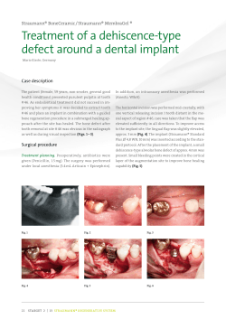
Ridge Expansion and Immediate Implant
Placement in the Esthetic Zone
Lakshman Dene, D.D.S., B.D.S., M.Med.Sc., Ph.D.; Spyridon Condos, D.D.S.
Abstract
Implant placement and tooth restoration in the maxillary esthetic zone is
challenging. In the case reported
here, the treatment site was tooth # 8,
which had been extracted one year
previously. Available bone in three
dimensions was evaluated by computerized tomography. The bucco-lingual bone width at the crest was
3 mm to 4 mm wide, an inadequate
width for implant placement. Ridge
expansion was accomplished with
hand osteotomes, followed by tapered
drills. A 4.3 x 13 mm Nobel Biocare
implant was placed. Following osseointegration, a PFM crown, supported
by an esthetic abutment, was placed.
A very pleasing esthetic result was
achieved.
28 NYSDJ • MARCH 2010
IMPLANT PLACEMENT and tooth restoration in the esthetic zone can present a
challenge, even to the experienced operator. The fundamentals of esthetics, such as
facial and dental midlines, lip line at rest,
the smile line, incisal plane, occlusal plane
and the buccal corridor should receive
attention during the treatment planning
stage. More importantly, the gingival biotype, tooth shape, interproximal ridge
height, and position and height of the
papillae help in determining the treatment
sequence and modalities necessary to
achieve an esthetic result.1
The three dimensions of available
bone are important determinants of the
final result. Bone measurements need to be
made in 3 axes: 1. the x axis—mesio-distally; 2. y axis—vertically; and 3. z axis—
bucco-lingually. If the bone is present in
optimum amounts, a FP-1 prosthesis2 can
be fabricated. In most instances, the maxillary anterior bone is compromised
bucco-lingually. This may be because of
the thin cortical plate and 25% resorption
of bucco-lingual width of bone and the
decrease in height of 4 mm during the first
year after tooth loss.2 When the bone width
is compromised, augmentation becomes
necessary to increase the bone volume.
This will enable placement of an implant
to achieve a FP-1 prosthesis.
Bone augmentation could be accomplished by onlay grafting with autogenous
block grafts or with guided bone regeneration (GBR) using particulate autografts or
allografts covered by membranes. Block
grafting is accomplished with autogenous
grafts, usually obtained from the mandibular symphysis or ramus.3-5 This technique
requires a second surgical site.
Extraoral sites may also be used to
harvest autogenous bone. Problems with
extraoral sites include hospitalization,
expense and patient morbidity. Block
grafting could also be done with bone
allografts, such as J-Block (Puros). Block
grafts and GBR require a period of four to
six months prior to implant placement,
unless they are done simultaneously with
implant placement.
When the bucco-lingual bone width
is 3 mm or greater but less than 6 mm, to
allow implant placement, augmentation of
the alveolar ridge using a ridge expansion
technique is a viable option. The 3 mm of
A.
Figure 1. Removable acrylic prosthesis worn by
patient. Note: This exerts pressure on buccal gingiva, leading to increased bone resorption.
Figure 2. Buccal gingival tissue at tooth #8. Note
depression caused by appliance. Square shape of
tooth #9 (central incisor) is also seen.
B.
bone should have at least 1 mm of trabecular bone sandwiched between the cortical plates. That will ensure 1.5 mm of bone
(cortical and cancellous) on either side of
the split ridge and allow the bone to
spread and maintain a good blood supply.
Ridge expansion for single and multiple
implant sites have been documented.6-9
This will allow either immediate or
delayed implant placement.
(bucco-lingual) dimension needs to be
determined as well.The CT scan allows visualization of this third dimension, in addition
to the other two. It also provides information
on bone density in Hounsfield units.
The CT scan revealed that the buccolingual dimension of bone at the crest was
inadequate for implant placement (Figures
3A,B). There was adequate cortical and
cancellous bone to allow ridge expansion.
Clinical Case
Ridge Expansion: Technique
The patient was a 28-year-old Hispanic
female. Her chief complaint was that she
disliked her maxillary anterior removable
appliance (Figure 1). She requested a fixed
prosthesis, preferably an implant-supported one. Her medical history was non contributory. Her expectations were reasonable
and her psychological profile was good. She
was missing tooth #8, which had been
extracted one year earlier, followed by the
placement of a removable acrylic appliance. Extra- and intraoral examinations
were within normal limits, and her dentition was in a good state of repair.
Clinical examination of the alveolar
ridge and soft tissues revealed a thick gingival biotype. Tooth #9 was square in
shape. There was a buccal defect in the gingiva in the region of tooth #8 due to normal
shrinkage, probably exacerbated by pressure exerted from the removable appliance
(Figure 2). The periapical X-rays revealed
adequate bone height and mesio-distal
bone width.
Preoperative antibiotics were prescribed
and the patient was prepared in a sterile
environment. A papilla-sparing crestal
incision was made and full thickness
mucoperiosteal flaps were raised on the
buccal and palatal aspects of tooth #8
(Figure 4). Using a surgical guide, the exact
position for the implant was scored on the
ridge with a round bur. Once this position
was acceptable, the osteotomy was started
and extended vertically to about 5 mm with
a #15 blade. This was accomplished by gently tapping into the bony crest. A sequence
of osteotomes of increasing width and
shapes were then used (Figures 5 A,B,C).
Tatum’s angular osteotomes were used
initially and wiggled back and forth in a
mesio-distal direction with slight buccal
pressure. Tatum’s D osteotomes were used
next, with the curved portion toward the
buccal and the flat portion toward the
palatal. This would selectively force the
buccal plate outward without expanding
the palate.A sequence of round osteotomes
(Summers osteotomes, Steri-Oss osteotomes or
Tatum’s round osteotomes), both pointed
and flat ended, were used to continue the
bone expansion. The final instruments
closely matched the shape of the implant.
Computerized Tomography
The alveolar bone has three dimensions.
Periapical and panoramic X-rays allow visualization of two dimensions. The third
Figure 3. Computerized tomography of tooth
#8 area. A: thin crestal ridge; B: bucco-lingual
deficiency of crestal bone.
Figure 4. Supra-crestal incision and full thickness
mucoperiosteal flap refection.
A.
B.
C.
Figure 5. Hand osteotomes used for ridge expansion (A,B,C).
NYSDJ • MARCH 2010 29
Figure 6. Expanded ridge crest.
Figure 7. Placement of Nobel Biocare Replace
Select 4.3 mm x 13 mm implant.
Figure 8. Implant covered by surgical cover screw.
Figure 9. Coronally repositioned flap.
A.
B.
Figure 10. Periapical X-rays of implant (A) following
placement and (B) with prosthesis four months later.
Figure 11. Clinical picture of final prosthesis.
30 NYSDJ • MARCH 2010
The coronal portion of the ridge was
expanded (Figure 6).
When the ridge was wide enough, a
drill sequence was used to finalize the
osteotomy apically to the desired width and
length. A 4.3 mm x 13 mm Nobel Biocare
Replace Select implant with Tiunite was
placed and covered with a surgical cover
screw (Figures 7, 8).
The CT scan also showed a radiolucency at the periapical area of the extracted
tooth. This area was curetted and the
expanded ridge was filled with bone allograft (irradiated cancellous bone—Rocky
Mountain) and covered with a resorbable
membrane (Biomend Extend—Zimmer).
The flap was coronally repositioned with
primary closure (Figure 9).
Second Stage: Uncovery Surgery
The implant was exposed at the crest with
minimal flap reflection after four months.
Because of the thick gingival biotype, there
was no gingival recession. The surgical
cover screw was removed and a healing collar was screwed into place. The gingiva was
allowed to heal and mature for one month
before implant level impressions were
taken.
Implant Restoration
An implant level impression was taken with
a closed tray technique following placement
of an implant transfer post. Heavy body
polyvinyl siloxane impression material was
used for the impression. The implant transfer post was attached to the implant analog
before it was snapped back into the impression. The laboratory made a soft-tissue cast
and fabricated a porcelain-fused-to-highnoble metal crown using a 1 mm esthetic
abutment (Figures 10A, B, 11).
Discussion
Following tooth extraction, the socket
should be preserved by bone grafting. This
prevents the socket from decreasing in
width by 25% and the loss of 4 mm of bone
height in the year following extraction.2 A
conventional removable prosthesis with a
buccal flange exerts pressure on the buccal
and palatal gingiva, thereby constricting
blood vessels and reducing blood supply to
the area. This commonly leads to increased
bone loss and subsequent compromise of
tissue form. Ideally, the extraction site
should be temporarily restored with a fixed
restoration, such as a Maryland bridge or
bonded free-hand composite. A removable
prosthesis using an ovate pontic without a
flange can also be made.1 This type of pontic maintains good gingival contour and
allows for good emergence profile for the
final restoration. Fabrication of a removable prosthesis, as seen in Figure 1, should
be avoided.
The use of computerized tomography
is essential for several reasons. The level of
distortion is minimal at 1.8% with the CT
scans. In comparison, panoramic X-rays
have a 23.5% distortion; with periapical
X-rays, it is 14%.10 The CT image also provides the third dimension—the buccolingual. This dimension is critical to
implant placement.
Following implant placement, 1.5 mm
to 2 mm of bone should remain on the buccal and lingual aspects of the implant at the
bone crest. This measurement allows the
operator to determine if adequate bone is
available to sustain this requirement. In the
patient whose case is reported here, it was
evident from the CT scan that there was
insufficient bone to satisfy this criterion
(Figures 3 A, B).
When the bone width is < 3mm, onlay
grafting with autogenous block grafts3 or
an allograft is necessary. An increase in
bone width using distraction osteogenesis,11 piezoelectric surgery12 and the
Meisinger split control bone expansion13
has also been reported, but is less predictable for single implant sites.
There are significant advantages to
using ridge expansion rather than onlay
grafting. These include simultaneous
implant placement and grafting, lower cost,
lower possibility of cross-infection from
graft materials and lower morbidity. This
technique has greater predictability,since the
area that is grafted is essentially a five-wall
bony defect, with excellent blood supply.
Onlay grafts are by definition used for
one to three wall defects, with the predictability of the graft going down with
fewer walls. It is important to note that the
entire ridge was not split in this case, only
the coronal portion, which was too thin.The
apical portion of bone was not split; it was
treated in the traditional manner with drills
and osteotomes. This area of bone was used
to stabilize and support the implant.
There are several disadvantages to this
technique. It cannot increase height, only
width. It is a very difficult and operatordependent technique, with a substantial
learning curve. And it is more difficult to
perform on a single tooth than on entire
ridges, where the operator can take advantage of the elasticity of a long ridge of bone.
The author has successfully taken large
ridges in the maxilla 2 mm wide and
expanded them to 5 mm to 6 mm wide. If
an increase in height is desired, other techniques, such as onlay grafting, subantral
augmentation, distraction osteogenesis or
nerve repositioning, must be used.
In the case reported here, there was
between 3 mm and 4 mm of bone coronally, which did not allow implant placement.
There was trabecular bone with cortical
bone on either side. This was an ideal case
for bone expansion.7-10
6.
Conclusion
This report has demonstrated the successful use of hand osteotomes in expanding
the alveolar ridge at a single implant site. It
also shows that this technique allows for
immediate implant placement. Most importantly, from the patient’s perspective, a very
pleasing final esthetic result was achieved. ■
Queries about this article can be sent to Dr. Dene at
[email protected].
REFERENCES
1. Sclar AG. Soft Tissue and Esthetic Considerations in
Implant Therapy. Carol Stream, IL: Quintessence
Publishing Co. 2003.
2. Misch CE. Contemporary Implant Dentistry. St. Louis,
MO: Mosby Elsevier Publishing Co. 2008.
3. Garg AK, Morales MJ, Navarro I, Duarte F. Autogenous
mandibular bone grafts in the treatment of the
resorbed maxillary anterior alveolar ridge: rationale
and approach. Implant Dent 1998;7(3):169-176.
4. Gungormus M, Yavuz MS. The ascending ramus of the
mandible as a donor site in maxillofacial bone grafting.
J Oral Maxillofac Surg 2002;60:1316-1318.
5. Kaufman E, Wang Peter D. Localized vertical maxillary
7.
8.
9.
10.
11.
12.
13.
ridge augmentation using symphyseal bone cores. A
technique and case report. Int J of Oral & Maxillofac
Implants 2003;18:293-298.
Duncan JM, Westwood M. Ridge widening for the thin
maxilla.A clinical report. Int J Oral Maxillofac Implants
1997;12:224-227.
Elian N, Jalbout Z, Ehrlich B, Classi A, Cho Sang-Choon,
Kahtani Fahaed-Al, Froum S, Tarnow D.A two stage full
arch ridge expansion technique. Review of the literature and clinical guidelines. Implant Dent March,
2008;17(1):16-20.
Guirado JL, Yuguero MR, Carrion del Valle MJ et al. A
maxillary ridge splitting technique followed by immediate placement of implants: a case report. Implant
Dent 2005;14(1):14-20.
Koo S, Dibart S, Weber HP. Ridge splitting technique
with simultaneous implant placement. Compendium
Contin Educ Dent March 2008;29(2):106-110.
Sonick M, Abrahams J, Faiella R. A comparison of the
accuracy of periapical, panoramic and computerized
tomographic radiographs in locating the mandibular
canal. J Oral and Maxillofac Implants 1994;9(4)455-460.
Takahashi T, Funaki K, Shintani H, Haruoka T. Use of
horizontal alveolar distraction osteogenesis for implant
placement in a narrow alveolar ridge. A case report. Int
J of Oral & Maxilofac Implants 2004:19:291-294.
Vercellotti T.Piezoelectric surgery in implantology.A case
report. A new piezoelectric ridge expansion technique.
Int J Periodontics Restorative Dent 2000; 20:359-365.
Siddiqui AA, Sosovicka M. Lateral bone condensing &
expansion for placement of endosseous dental
implants: a new technique. J Oral Implantology
2006;32(2):87-94.
NYSDJ • MARCH 2010 31


© Copyright 2026