ABC
docz
Explore
Log in
Create new account
Download
Report
technology and computing
consumer electronics
telephones
mobile phones
MPIP-618W-A User Manual V1.2.0
April 2015 EVOC
Authorization Letter M S
Community Alert
Preparedness M.R.A.P. Vehicle Operator Course National Institute
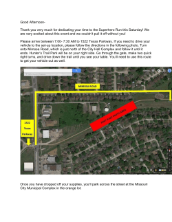
Thank you very much for dedicating your time to the Superhero Run
Document 267847
Std : VI SUBJECT NAME OF THE CHAPTER
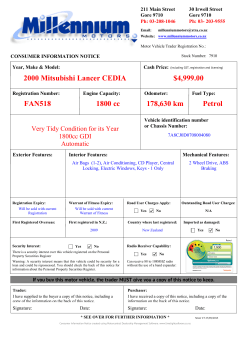
View CIN Card - Millennium Motors
CEC News Release â Announcing the North Fork project award
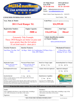
2011 Ford Ranger XL $24,999.00 FSY280 3000 cc 116,249 km Diesel
© Copyright 2026
About abcdocz
DMCA / GDPR
Report